


 Loading...
GE Fanuc Automation
Computer Numerical Control Products
Symbolic CAP T
Basic Module V1
Operator’s Manual
GFZ-62824EN/02 |
November 1998 |

GFL-001
Warnings, Cautions, and Notes as Used in this Publication
Warning
Warning notices are used in this publication to emphasize that hazardous voltages, currents, temperatures, or other conditions that could cause personal injury exist in this equipment or may be associated with its use.
In situations where inattention could cause either personal injury or damage to equipment, a Warning notice is used.
Caution
Caution notices are used where equipment might be damaged if care is not taken.
Note
Notes merely call attention to information that is especially significant to understanding and operating the equipment.
This document is based on information available at the time of its publication. While efforts have been made to be accurate, the information contained herein does not purport to cover all details or variations in hardware or software, nor to provide for every possible contingency in connection with installation, operation, or maintenance. Features may be described herein which are not present in all hardware and software systems. GE Fanuc Automation assumes no obligation of notice to holders of this document with respect to changes subsequently made.
GE Fanuc Automation makes no representation or warranty, expressed, implied, or statutory with respect to, and assumes no responsibility for the accuracy, completeness, sufficiency, or usefulness of the information contained herein. No warranties of merchantability or fitness for purpose shall apply.
©Copyright 1998 GE Fanuc Automation North America, Inc.
All Rights Reserved.

B-62824EN/02 |
SAFETY PRECAUTIONS |
SAFETY PRECAUTIONS
This manual includes safety precautions for protecting the user and preventing damage to the machine. Precautions are classified into Warnings and Cautions according to their bearing on safety. Also, supplementary information is described as Notes. Read the Warnings, Cautions, and Notes thoroughly before attempting to use the machine.
WARNING
Applied when there is a danger of the user being injured or when there is a danger of both the user being injured and the equipment being damaged if the approved procedure is not observed.
CAUTION
Applied when there is a danger of the equipment being damaged, if the approved procedure is not observed.
NOTE
Notes is used to indicate supplementary information other than
Warnings and Cautions.
¡ Read this manual carefully, and store it in a safe place.
NOTE
In this manual, a program used to specify operations of the CNC machine tool is referred to as "NC data." In CNC machine tool manuals, such a program may be referred to as a "machining program," "part program," or "program," in place of "NC data." The above precautions must also be applied to those programs in a CNC machine tool manual, assuming that the programs have the same usage and purpose as those of the NC data as described in this manual.
s-1

SAFETY PRECAUTIONS |
B-62824EN/02 |
GENERAL WARNINGS AND CAUTIONS RELATING TO USE WITH A CNC
This chapter presents the safety precautions which must be observed when the conversational automatic programming function, described in this manual, is used with the CNC machine tool.
WARNING
(1)Before starting any operation related to the conversational function (such as preparing NC data or running an NC data program), thoroughly check the work area to ensure safety. For example, close the door of the machine, if it is open. Failure to ensure safety may result in death or serious injury. Operating the machine with incorrect NC data may result in the tool colliding with the workpiece and/or machine, possibly causing damage to the machine, workpiece, and/or the tool itself, or injury to the user.
(2)When the tool offset function is used, before activating the machine, check the direction and value of the offset to ensure that the tool will not collide with the workpiece or machine. Any collision may cause damage to the tool, machine, and/or workpiece, or injury to the user.
(3)Before starting the NC data program prepared using the conversational function, thoroughly check the NC data to ensure that the tool path and machining processes are set correctly, and that the tool will not collide with the workpiece or machine (including the chuck and tailstock). Before starting a production run, perform a dry run to ensure that the tool will not collide with the workpiece or machine (including the chuck and tailstock). For example, start the NC data program without mounting a workpiece on the machine. Any collision may cause damage to the tool, machine, and/or workpiece, or injury to the user.
(4)Before using the conversational function to perform programming, ensure that all the data required for the conversational function, including tool data and cutting condition data, is set correctly. If these data values are not set appropriately, the cutting conditions required for machining may not be set correctly, possibly causing damage to the tool, machine, and/or workpiece, or injury to the user.
(5)After pressing the power-on button, do not touch any keys on the keyboard until the window is displayed. Some keys are specifically designed for maintenance or other special operations; if any of these keys is pressed before the window is displayed, the machine may behave unexpectedly.
s-2

B-62824EN/02 |
SAFETY PRECAUTIONS |
GENERAL WARNINGS AND CAUTIONS RELATING TO USE WITH A PERSONAL COMPUTER
This chapter presents the safety precautions which must be observed when the software, described in this manual, is used with a personal computer, and when the prepared NC data(Note) is used with a CNC machine tool.
WARNING
(1)Before using NC data with a CNC machine tool to perform a production run, ensure that the machine and tool under the control of the NC data commands will operate safely. If incorrect NC data is used carelessly, or if correct NC data is handled improperly, the machine or tool may behave unexpectedly, possibly causing damage to the machine, tool, and/or workpiece, or injury to the user.
(2)In this software, once NC data has been automatically created, whether the NC data program runs appropriately for the CNC machine tool is not checked. When using the NC data with a CNC machine tool to perform a production run, follow the instructions in
(1) above.
(3)In this software, whether other software for drawing or checking NC data runs appropriately for the CNC machine tool is not checked. When using the NC data with a CNC machine tool to perform a production run, follow the instructions in (1) above.
(4)When even proven NC data is used repeatedly, the contents of the NC data may have changed when it is input to the CNC machine tool, due to degradation in the NC data storage, or changes in the communication facilities for data transfer. When using the NC data with a CNC machine tool to perform a production run, follow the instructions in (1) above.
s-3
B-62824EN/02 |
PREFACE |
PREFACE
Thank you for purchasing FANUC Symbolic CAP T.
The FANUC Symbolic CAP T software provides total support of all lathing phases from blank figure creation and parts figure creation through to NC data creation. To take full advantage of the functions and features of FANUC symbolic CAP T, users are advised to read and become familiar with the entire contents of this manual.
FANUC Symbolic CAP T is compatible with Microsoft® Windows®. This manual does not attempt to explain basic Windows operations. Those users who are unfamiliar with Windows should first read the Windows documentation for an explanation of Windows fundamentals.
FANUC Symbolic CAP T uses the following products, whose copyright is owned by Microsoft of the USA.
∙Microsoft® Windows® Software Development Kit
∙Microsoft® Windows® Visual C++TM
∙Microsoft® Windows® Visual BasicTM
∙Microsoft® Windows® Visual Control Pack
NOTE
Microsoft and Windows are registered trademarks of Microsoft
Corporation of the USA. Visual C++ and Visual Basic are trademarks
of Microsoft Corporation.
Checking the contents of the package
Immediately after opening the package, check that you have received the following items.
1)Floppy disks
∙For OPEN CNC
FANUC Symbolic CAP T Basic module V1 (A08B-9110- J550#EN07)
∙For Personal computer
FANUC Symbolic CAP T Basic module V1 (A08B-9310- J550#EN07)
2)Protector (Only for Personal computer)
FANUC Symbolic CAP T Basic module Protector (A08B-0080-
p-1

PREFACE |
B-62824EN/02 |
J550#P550)
3)Operator's manual
FANUC Symbolic CAP T Basic module Operator's Manual (this document)
About this manual
This manual consists of the sections described below.
PREFACE
Describes the use of this manual and related materials.
Also, briefly describes some of the features of FANUC Symbolic CAP
T.
1.SETUP
Describes the environment needed to run FANUC Symbolic CAP T, and the method of setting up and enabling the use of FANUC Symbolic CAP T.
2.BASIC OPERATION
Explains how to start and stop FANUC Symbolic CAP T, and describes its basic operations. Also, briefly describes the functions provided by the side menu and menu bar.
3.PROGRAMMING EXAMPLE
Provides an example of the operation of FANUC Symbolic CAP T.
4.BLANK FIGURE CREATION
Describes the types of blank figures, and explains their creation.
5.PARTS FIGURE CREATION
Describes how to create parts figure by means of symbolic figure input.
6.PRE-MACHINING SETTING
Explains how to set the machine's home position and select tooling data; these operations must be completed before machining definition can be performed.
7.MACHINING DEFINITION
Describes the specification of machining types, machining area, and machining conditions, based on the blank and part figures. Also explains how these items can be determined automatically.
p-2
B-62824EN/02 |
PREFACE |
8.NC DATA PREPARATION
Describes how to prepare the NC data for a specified process. Also explains how to confirm NC data by animated simulation, and how to print NC data and process list.
9.TOOL PATH EDITING
Explains how to edit tool paths you prepared.
10.SAVING AND LOADING FILE
Describes how to save a newly created program under a specified name, and how to load a program that was created and saved previously.
11.CREATING NEW PROGRAM
Describes how to discard an existing program and create a new one.
12.FIGURE CREATION
Explains the basics of figure creation by means of CAD entry. Also describes how figures are copied and modified.
13.CUTTING CONDITION DATA
Describes how data is registered and modified, including data on the workpiece, tools, and machining conditions, needed to enable the automatic setting of machining conditions.
14.CUTTING CONDITION DATA UTILITY
Explains how to input and output cutting condition data.
15.TOOL DATA AND TOOLING DATA
Describes how to select the tool data to be referenced at Machining Definition, and how to register new tools and modify existing tool data.
16.TOOL/TOOLING DATA UTILITY
Explains how to input and output tool/tooling data.
17.NC MACHINE SETTING
Describes how to specify the technical data for the machine and CNC.
18.FILE TRANSFER
Describes how to transfer NC data to the CNC unit or other units.
19.PLOTTING
Describes how to output NC data from the drawing window to the plotter.
p-3

PREFACE |
B-62824EN/02 |
20.CAD DATA INPUT/OUTPUT
Describes the exchange of data between Symbolic CAP T and general CAD software. Also explains the precautions to be observed when using FANUC Symbolic CAP T to handle data prepared in another CAD system.
21.FAPT LANGUAGE FIGURE INPUT
Describes a function that is tended to analyze and execute part program figure definition statements written in FAPT language, and convert them to figure entities that can to be saved to the Symbolic CAP figure databases.
22.DIMENSION MEASUREMENT
Explains how to measure coordinates and distances from figures.
23.STANDARD SETTING
Describes the setting of the initial values displayed on each conversational window.
24.PARAMETER SETTING
Describes the specification of parameters related to FANUC Symbolic CAP T, such as the part figures and tool path colors to be prepared, the sequence in which axes are moved during approach/escape, and whether data is saved automatically at regular intervals.
25.TOOL BAR SETTING
Describes how to modify the contents of the tool bar.
26.TROUBLESHOOTING
Describes the procedure to be followed if a problem occurs.
Also lists the errors that may occur.
27.APPENDIX
Contains information that should be read as required, such as the function codes used in NC machine files.
Notations
∙Product name abbreviations
Major product names are abbreviated as stated below.
FANUC Symbolic CAP T |
-> Symbolic CAP T |
|
FANUC Symbolic CAP T Basic module |
-> |
Basic module |
FANUC Symbolic CAP T Basic module |
|
|
Protector |
-> |
Protector |
p-4
B-62824EN/02 |
PREFACE |
Microsoft® Windows® |
-> Windows |
∙Keys
When a sequence of keys are to be pressed and held down, the keys in the sequence are indicated with an intervening dash (-), as shown below:
Example) CTRL-ALT-TAB, ALT-F4
∙Menus
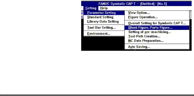
When a command is to be selected from the menu bars, a right arrow (=>) is used to link the menus in the sequence, as shown below:
“First menu => second menu => third menu”
Example) The menus shown below would be indicated as shown below: “Setting => Parameter Setting => Blank Figure, Parts Figure”
∙Window examples
The windows shown in this document are merely examples. Note that the window layout and file names used may vary depending on the equipment or the resolution of the display unit you are using.
Features of Symbolic CAP T
∙Operation on Windows
Comfortable operating environment is afforded by Windows which provides a de facto standard user interface.
Even inexperienced users can use the system by interactive operation using graphical menus and a mouse.
∙User-friendly operating procedure that is easy to use, even by beginners
Symbolic CAP T is easy even for beginners to use, thanks to its support of graphical menus (icons) and mouse-driven conversational processing. In addition, it provides a wealth of help messages.
p-5
PREFACE |
B-62824EN/02 |
∙Operating procedure for experienced operators
Symbolic CAP T commands can be entered from the keyboard, enabling experienced operators to operate the system quickly.
∙Customizing functions
The user can improve the operability or add functions to suit the usage of customers. Customizing to call frequently used functions by a simple operation on tool bar is possible.
∙One-click switching of the window
The window can be switched between that for machining definition and that for figure creation simply by clicking a button. Therefore, even if a figure is found to be missing during machining definition, figure input need not be repeated from the very beginning.
∙Symbolic figure input
Blank and parts figure can be entered using conventional symbolic figure input based on arrows.
∙Fully automatic process determination
An optimum machining type, a tool, a portion to be cut, and machining conditions can be automatically selected simply by entering blank and part figures. Even beginners can create machining programs quickly and easily.
∙Machining simulation
Three-dimensional animated machining simulation and tool path drawing are performed simultaneously. Animated machining simulation allows the operator to actually observe the progress of machining. Tool path drawing enables the operator to check the tool path generated by a machining program in detail.
∙Tool path editing function
The tool path editing function enables editing tool paths generated on Symbolic CAP T as figure images, using a mouse.
It is possible to re-prepare NC data from edited tool paths.
p-6

Table of Contents
B-62824EN/02
SAFETY PRECAUTIONS ................................................................................................ |
s-1 |
GENERAL WARNINGS AND CAUTIONS RELATING TO USE WITH A CNC ............... |
s-2 |
GENERAL WARNINGS AND CAUTIONS RELATING TO USE WITH A |
|
PERSONAL COMPUTER ................................................................................................ |
s-3 |
PREFACE ........................................................................................................................ |
p-1 |
Checking the contents of the package ............................................................................................. |
p-1 |
About this manual ........................................................................................................................... |
p-2 |
Notations......................................................................................................................................... |
p-4 |
Features of Symbolic CAP T ........................................................................................................... |
p-5 |
1 SETUP ............................................................................................................................ |
1 |
1.1 Prior to Setting Up (Operating Environment) ................................................................................ |
1 |
1.1.1 Prerequisites .................................................................................................................................................... |
1 |
1.1.2 Other usable devices ........................................................................................................................................ |
2 |
1.2 Setting Up Symbolic CAP T ......................................................................................................... |
3 |
1.2.1 About Setup..................................................................................................................................................... |
3 |
1.2.2 Setting up an optional module .......................................................................................................................... |
6 |
1.2.3 Reinstalling Symbolic CAP T........................................................................................................................... |
8 |
1.2.4 About the protector (Only for use with a personal computer) ............................................................................ |
8 |
2 BASIC OPERATION ....................................................................................................... |
9 |
2.1 Fundamentals .............................................................................................................................. |
9 |
2.1.1 Starting Symbolic CAP T ................................................................................................................................. |
9 |
2.1.2 Terminating Symbolic CAP T .......................................................................................................................... |
9 |
2.1.3 Reading the latest information about Symbolic CAP T ..................................................................................... |
9 |
2.1.4 Other Symbolic CAP T icons............................................................................................................................ |
9 |
2.2 Contents of Symbolic CAP T Window ........................................................................................ |
11 |
2.2.1 Title bar......................................................................................................................................................... |
11 |
2.2.2 Side menu...................................................................................................................................................... |
12 |
2.2.3 Menu bar ....................................................................................................................................................... |
13 |
2.2.4 Tool bar ......................................................................................................................................................... |
13 |
2.2.5 Drawing window............................................................................................................................................ |
13 |
2.2.6 Prompt area ................................................................................................................................................... |
14 |
2.2.7 Status window ............................................................................................................................................... |
15 |
2.3 Basic Operation.......................................................................................................................... |
16 |
2.3.1 Using the Help function to become familiar with the operating procedure...................................................................... |
16 |
2.3.2 Confirming the version................................................................................................................................... |
16 |
2.3.3 Modifying the operation flow ......................................................................................................................... |
17 |
2.4 Functions Provided by Side Menu .............................................................................................. |
19 |
2.4.1 Programming mode ........................................................................................................................................ |
19 |
2.4.2 Figure creation mode ..................................................................................................................................... |
19 |
2.5 Functions Provided by Menu Bar................................................................................................ |
26 |
2.5.1 File menu ...................................................................................................................................................... |
26 |
2.5.2 Modify menu ................................................................................................................................................. |
27 |
c-1

Table of Contents |
B-62824EN/02 |
|
|
2.5.3 Edit menu ...................................................................................................................................................... |
28 |
|
2.5.4 View menu .................................................................................................................................................... |
30 |
|
2.5.5 Auxiliary menu .............................................................................................................................................. |
31 |
|
2.5.6 Setting menu.................................................................................................................................................. |
32 |
|
2.5.7 Help menu ..................................................................................................................................................... |
33 |
2.6 |
Functions Provided by the Tool Bar............................................................................................ |
34 |
2.7 |
Flow of Operation....................................................................................................................... |
35 |
|
2.7.1 Overview of each function.............................................................................................................................. |
35 |
|
2.7.2 Overview of data............................................................................................................................................ |
36 |
2.8 Layers ......................................................................................................................................... |
38 |
|
|
2.8.1 About layers................................................................................................................................................... |
38 |
|
2.8.2 Major classification of layers.......................................................................................................................... |
38 |
|
2.8.3 Figure creation layer setting ........................................................................................................................... |
39 |
2.9 |
Drawing Format Setting.............................................................................................................. |
40 |
3 PROGRAMMING EXAMPLE ........................................................................................ |
41 |
|
3.1 |
Flow of Operation....................................................................................................................... |
41 |
|
3.1.1 Procedure....................................................................................................................................................... |
41 |
|
3.1.2 Explanation of each step ................................................................................................................................ |
42 |
|
3.1.3 Example of operation ..................................................................................................................................... |
43 |
4 BLANK FIGURE CREATION........................................................................................ |
54 |
|
4.1 |
Blank Figure Creation................................................................................................................. |
54 |
4.2 |
Special Figure ............................................................................................................................ |
56 |
4.3 |
Blank Figure Color/Line Type Modification ................................................................................. |
58 |
5 PARTS FIGURE CREATION ........................................................................................ |
59 |
|
5.1 |
Turning Figure Creation.............................................................................................................. |
59 |
5.2 |
Symbolic Input Method............................................................................................................... |
61 |
|
5.2.1 Entity selection .............................................................................................................................................. |
61 |
|
5.2.2 Symbolic figure data input ............................................................................................................................. |
62 |
|
5.2.3 Symbolic Figure data editing.......................................................................................................................... |
78 |
|
5.2.4 Symbolic figure creation by figure reference................................................................................................... |
80 |
6 PRE-MACHINING SETTING......................................................................................... |
84 |
|
6.1 |
Selecting Tooling Data ............................................................................................................... |
85 |
6.2 |
Selecting an NC Machine File .................................................................................................... |
86 |
6.3 |
Setting the Home Position .......................................................................................................... |
87 |
6.4 |
Setting the Index Position........................................................................................................... |
88 |
6.5 |
Setting the Chuck....................................................................................................................... |
89 |
|
6.5.1 Setting items of the chuck .............................................................................................................................. |
89 |
|
6.5.2 Chuck figure registration/edit window............................................................................................................ |
91 |
7 MACHINING DEFINITION............................................................................................. |
93 |
|
7.1 |
Machining Definition Window ..................................................................................................... |
94 |
7.2 |
Selecting the Machining Type..................................................................................................... |
95 |
7.3 |
Specifying the Cutting Area and Condition Data ......................................................................... |
97 |
|
7.3.1 Specifying the Cutting Area ........................................................................................................................... |
97 |
c-2

B-62824EN/02 |
Table of Contents |
||
|
7.3.2 Location of the division point and the cutting area........................................................................................ |
|
101 |
|
7.3.3 Condition setting.......................................................................................................................................... |
|
105 |
|
7.3.4 Specifying Another Area .............................................................................................................................. |
|
107 |
7.4 |
Changing and Modifying the Machining Process........................................................................ |
|
109 |
7.5 |
Defining New Machining Process .............................................................................................. |
|
111 |
7.6 |
Fully Automatic Determination .................................................................................................. |
|
112 |
8 NC DATA PREPARATION ......................................................................................... |
|
115 |
|
8.1 |
Preparing and Displaying NC Data ............................................................................................ |
|
115 |
8.2 |
NC Data Preparation Window.................................................................................................... |
|
116 |
8.3 |
Process Order Editing Window.................................................................................................. |
|
119 |
8.4 |
NC Data Preparation Data Setting Window ............................................................................... |
|
121 |
8.5 |
Animation Window .................................................................................................................... |
|
122 |
8.6 |
Data Setting Window for Animated Simulation .......................................................................... |
|
124 |
8.7 |
Writing NC Data to a Floppy Disk and Transferring NC Data to a Peripheral Device |
.................125 |
|
8.8 |
Printing NC Data and a Process Table ...................................................................................... |
|
126 |
9 TOOL PATH EDITING................................................................................................ |
|
127 |
|
9.1 |
Tool Path Editing....................................................................................................................... |
|
127 |
|
9.1.1 Tool paths subjected to editing..................................................................................................................... |
|
127 |
|
9.1.2 Unit of editing ............................................................................................................................................. |
|
128 |
|
9.1.3 Coordinate system used for tool path editing ................................................................................................ |
|
128 |
|
9.1.4 Editing......................................................................................................................................................... |
|
128 |
9.2 |
Execution of Tool Path Editing .................................................................................................. |
|
129 |
9.3 |
Tool Path Editing Dialog Box..................................................................................................... |
|
130 |
|
9.3.1 Machining process list ................................................................................................................................. |
|
130 |
|
9.3.2 Selecting a tool path for editing.................................................................................................................... |
|
130 |
|
9.3.3 Deleting tool paths....................................................................................................................................... |
|
131 |
|
9.3.4 Terminating tool path editing ....................................................................................................................... |
|
131 |
9.4 |
Editing Movement Entities......................................................................................................... |
|
132 |
|
9.4.1 Adding movement entities............................................................................................................................ |
|
132 |
|
9.4.2 Erasing movement entities ........................................................................................................................... |
|
133 |
|
9.4.3 Trimming/Extending movement entities....................................................................................................... |
|
133 |
|
9.4.4 Undoing/redoing editing............................................................................................................................... |
|
133 |
|
9.4.5 Specifying start entities................................................................................................................................ |
|
134 |
|
9.4.6 Checking tool paths for continuity ................................................................................................................ |
|
135 |
|
9.4.7 Listing entities ............................................................................................................................................. |
|
136 |
|
9.4.8 Canceling movement entity editing............................................................................................................... |
|
136 |
|
9.4.9 Terminating movement entity editing ........................................................................................................... |
|
137 |
10 SAVING AND LOADING FILE.................................................................................. |
|
138 |
|
10.1 Saving a File ........................................................................................................................... |
|
138 |
|
10.2 Loading a File.......................................................................................................................... |
|
139 |
|
11 CREATING NEW PROGRAM................................................................................... |
|
140 |
|
12 FIGURE CREATION ................................................................................................. |
|
141 |
|
12.1 Types of Figures...................................................................................................................... |
|
141 |
|
12.2 Specifying a Radius, Distance, and Angle ............................................................................... |
|
142 |
|
c-3

Table of Contents |
B-62824EN/02 |
|
12.3 |
Specifying Positions ................................................................................................................ |
143 |
12.4 |
Selecting Entities..................................................................................................................... |
145 |
12.5 |
Coordinate System.................................................................................................................. |
147 |
|
12.5.1 World coordinate system ............................................................................................................................ |
147 |
|
12.5.2 Machining plane coordinate system ............................................................................................................ |
147 |
12.6 |
Modifying Figures by Extension/Trimming ............................................................................... |
148 |
12.7 |
Copying Figures ...................................................................................................................... |
149 |
12.8 |
Creating Polygons ................................................................................................................... |
155 |
12.9 Fitting Curve ........................................................................................................................... |
156 |
|
|
12.9.1 Creation method of a fitting curve .............................................................................................................. |
156 |
|
12.9.2 Adjusting the creation method of a fitting curve.......................................................................................... |
156 |
12.10 Offset .................................................................................................................................... |
159 |
|
|
12.10.1 Outward offset for a corner....................................................................................................................... |
159 |
|
12.10.2 Inward offset for a corner ......................................................................................................................... |
160 |
13 CUTTING CONDITION DATA .................................................................................. |
162 |
|
13.1 Overview................................................................................................................................. |
162 |
|
13.2 |
Functions ................................................................................................................................ |
164 |
13.3 |
Starting of Editing Cutting Condition Data................................................................................ |
165 |
13.4 |
Adding a Material Name .......................................................................................................... |
166 |
13.5 |
Deleting a Material Name [Edit Cutting Condition Data]........................................................... |
168 |
13.6 |
Editing Cutting Condition Data................................................................................................. |
169 |
|
13.6.1 Modifying cutting condition data on a machining type basis........................................................................ |
169 |
|
13.6.2 Adding cutting condition data..................................................................................................................... |
170 |
|
13.6.3 Modifying cutting condition data ................................................................................................................ |
175 |
|
13.6.4 Deleting cutting condition data................................................................................................................... |
175 |
|
13.6.5 Changing the order of the tool types ........................................................................................................... |
175 |
|
13.6.6 Deleting cutting condition data on a machining type basis .......................................................................... |
175 |
13.7 |
Calculating Method of the Machining Condition Data............................................................... |
176 |
14 CUTTING CONDITION DATA UTILITY.................................................................... |
179 |
|
14.1 |
Functions ................................................................................................................................ |
179 |
14.2 |
Starting the Cutting Condition Data Utility................................................................................ |
180 |
14.3 |
Selecting Utility Functions ....................................................................................................... |
181 |
14.4 |
Outputting Cutting Condition Files ........................................................................................... |
182 |
14.5 |
Inputting Cutting Condition Files.............................................................................................. |
184 |
14.6 |
Changing Cutting Condition Files ............................................................................................ |
186 |
14.7 |
Uniting Cutting Condition Files ................................................................................................ |
189 |
15 TOOL DATA AND TOOLING DATA ........................................................................ |
192 |
|
15.1 Overview................................................................................................................................. |
192 |
|
15.2 |
Functions ................................................................................................................................ |
194 |
15.3 |
Starting of Tool Data/Tooling Data Editing............................................................................... |
195 |
15.4 |
Addition of Tooling Data .......................................................................................................... |
196 |
15.5 |
Deleting a Tooling ................................................................................................................... |
198 |
15.6 |
Modification of the Tooling Data .............................................................................................. |
199 |
|
15.6.1 Adding or inserting the tool data for a tool into the tooling data .................................................................. |
199 |
|
15.6.2 Registering a new tool and adding or inserting the data into the tooling data............................................... |
200 |
c-4

B-62824EN/02 |
Table of Contents |
|
|
15.6.3 Modifying tool registered in the tooling data .............................................................................................. |
202 |
|
15.6.4 Duplicating a tool in tooling data................................................................................................................ |
202 |
|
15.6.5 Changing the order of the tools in the tooling data ...................................................................................... |
202 |
|
15.6.6 Deleting tooling from the tooling data ........................................................................................................ |
203 |
|
15.6.7 Registering a new tool and adding or inserting tool data ............................................................................. |
203 |
|
15.6.8 Modifying tool registered in the tool data ................................................................................................... |
203 |
|
15.6.9 Duplicating the tool in the tool data............................................................................................................ |
203 |
|
15.6.10 Changing the order of the tools in the tool data......................................................................................... |
204 |
|
15.6.11 Deleting tool from the tool data ................................................................................................................ |
204 |
|
15.6.12 Adding or deleting a tool material name only............................................................................................ |
204 |
16 TOOL/TOOLING DATA UTILITY ............................................................................. |
205 |
|
16.1 Functions ................................................................................................................................ |
205 |
|
16.2 |
Starting the Tool/Tooling Data Utility ....................................................................................... |
206 |
16.3 |
Selecting Utility Functions ....................................................................................................... |
207 |
16.4 |
Outputting Tool/Tooling Files................................................................................................... |
208 |
16.5 |
Inputting Tool/Tooling Files ..................................................................................................... |
210 |
16.6 |
Changing Tooling Files............................................................................................................ |
212 |
17 NC MACHINE SETTING ........................................................................................... |
214 |
|
17.1 |
NC Machine File..................................................................................................................... |
214 |
17.2 |
Overview of NC Data Preparation Procedure .......................................................................... |
215 |
17.3 |
Modifying the NC Data Output Format..................................................................................... |
216 |
17.4 |
Machine Specifications............................................................................................................ |
219 |
|
17.4.1 NC machine name...................................................................................................................................... |
219 |
|
17.4.2 Home position/index position..................................................................................................................... |
219 |
|
17.4.3 Total number of axes/number of simultaneously controlled axes................................................................. |
219 |
|
17.4.4 Feedrate..................................................................................................................................................... |
220 |
|
17.4.5 Spindle speed............................................................................................................................................. |
220 |
|
17.4.6 Whether to use the ATC function ............................................................................................................... |
220 |
17.5 |
CNC Specifications ................................................................................................................. |
221 |
|
17.5.1 Address setting .......................................................................................................................................... |
221 |
|
17.5.2 G code ....................................................................................................................................................... |
222 |
|
17.5.3 M code....................................................................................................................................................... |
222 |
|
17.5.4 Arbitrary character string ........................................................................................................................... |
223 |
|
17.5.5 Specifying required functions ..................................................................................................................... |
223 |
17.6 |
NC Data Format ...................................................................................................................... |
225 |
|
17.6.1 Example of referencing NC data formats .................................................................................................... |
225 |
|
17.6.2 Timing of NC data format reference ........................................................................................................... |
226 |
17.7 |
Example of NC Data Output .................................................................................................... |
239 |
17.8 |
NC Machine Setting Tool Operation ........................................................................................ |
241 |
17.9 |
Customization ......................................................................................................................... |
242 |
|
17.9.1 File configuration....................................................................................................................................... |
242 |
|
17.9.2 Modifying initial values ............................................................................................................................. |
243 |
|
17.9.3 Modifying setting item names .................................................................................................................... |
244 |
|
17.9.4 Deleting setting items ................................................................................................................................ |
245 |
|
17.9.5 Adding setting items .................................................................................................................................. |
246 |
18 FILE TRANSFER ...................................................................................................... |
247 |
|
18.1 |
Function Outline ...................................................................................................................... |
247 |
c-5

Table of Contents |
B-62824EN/02 |
18.1.1 Application software .................................................................................................................................. |
247 |
18.1.2 Devices to which data can be transmitted ................................................................................................... |
247 |
18.1.3 Data format that can be transmitted............................................................................................................ |
248 |
18.1.4 Transmission protocols............................................................................................................................... |
248 |
18.1.5 File operation functions.............................................................................................................................. |
248 |
18.2 Activating the File Transmission Tool ...................................................................................... |
249 |
18.2.1 Activation using the Symbolic CAP T output function ................................................................................ |
249 |
18.2.2 Activating only the File Transmission Tool ................................................................................................ |
250 |
18.2.3 Activating the File Transmission Manager ................................................................................................. |
250 |
18.3 File Transmission Tool Window............................................................................................... |
251 |
18.3.1 Menus........................................................................................................................................................ |
251 |
18.3.2 File specification areas............................................................................................................................... |
252 |
18.3.3 Buttons ...................................................................................................................................................... |
252 |
18.3.4 Operation guide ......................................................................................................................................... |
252 |
18.4 Operating Procedure ............................................................................................................... |
253 |
18.4.1 Selecting the device and setting the transmission conditions ....................................................................... |
253 |
18.4.2 Specifying files .......................................................................................................................................... |
253 |
18.4.3 Selecting a command ................................................................................................................................. |
254 |
18.4.4 Changing the contents of the transmission operation................................................................................... |
254 |
18.4.5 Starting transmission.................................................................................................................................. |
255 |
18.4.6 Checking the transmission status................................................................................................................ |
255 |
18.4.7 Ending the transmission operation.............................................................................................................. |
256 |
18.5 Outline of Processing for Each Function.................................................................................. |
257 |
18.5.1 Send .......................................................................................................................................................... |
257 |
18.5.2 Receive...................................................................................................................................................... |
257 |
18.5.3 Delete ........................................................................................................................................................ |
257 |
18.5.4 Clear.......................................................................................................................................................... |
258 |
18.5.5 Rename...................................................................................................................................................... |
258 |
18.5.6 Read-only and read/write ........................................................................................................................... |
258 |
18.5.7 Refresh ...................................................................................................................................................... |
259 |
18.6 Setting Transmission Conditions.............................................................................................. |
260 |
18.6.1 Setting procedure ....................................................................................................................................... |
260 |
18.6.2 Specifying the device and plotter................................................................................................................ |
263 |
18.6.3 Standard setting files.................................................................................................................................. |
263 |
18.6.4 Setting the communication conditions ........................................................................................................ |
264 |
18.6.5 Setting the transmission control conditions................................................................................................. |
265 |
18.6.6 Setting reception control conditions............................................................................................................ |
266 |
18.7 Transmission Schedule Management ...................................................................................... |
268 |
18.7.1 Contents of the window.............................................................................................................................. |
268 |
18.7.2 Changing the schedule ............................................................................................................................... |
269 |
18.7.3 Exiting the File Transmission Manager ...................................................................................................... |
270 |
18.8 Example Transmission Procedures ......................................................................................... |
271 |
18.8.1 Transmission to and from the CNC ............................................................................................................ |
271 |
19 PLOTTING................................................................................................................ |
272 |
19.1 Setting Up a Plotter ................................................................................................................. |
272 |
19.2 Procedures.............................................................................................................................. |
274 |
20 CAD DATA INPUT/OUTPUT .................................................................................... |
277 |
20.1 CAD Data Input/Output............................................................................................................ |
277 |
c-6

B-62824EN/02 |
Table of Contents |
|
|
20.1.1 CAD data................................................................................................................................................... |
277 |
|
20.1.2 Handling of CAD data by this system ......................................................................................................... |
278 |
20.2 |
DXF File Input/Output.............................................................................................................. |
279 |
|
20.2.1 Overview of DXF....................................................................................................................................... |
279 |
|
20.2.2 DXF file input ........................................................................................................................................... |
282 |
|
20.2.3 Setting the input conversion method........................................................................................................... |
284 |
|
20.2.4 DXF file output.......................................................................................................................................... |
289 |
|
20.2.5 Setting the output conversion method ......................................................................................................... |
291 |
20.3 |
Handling CAD Data Efficiently................................................................................................. |
295 |
20.4 |
Conversion Specifications for DXF File Input/Output ............................................................... |
296 |
|
20.4.1 DXF input conversion specifications .......................................................................................................... |
296 |
|
20.4.2 DXF output conversion specifications......................................................................................................... |
298 |
21 FAPT LANGUAGE FIGURE INPUT ......................................................................... |
301 |
|
21.1 Overview................................................................................................................................. |
301 |
|
|
21.1.1 Figure types that can be input..................................................................................................................... |
301 |
|
21.1.2 FAPT statement types that can be input...................................................................................................... |
301 |
21.2 |
Operation ................................................................................................................................ |
302 |
|
21.2.1 Start-up...................................................................................................................................................... |
302 |
|
21.2.2 Part program selection................................................................................................................................ |
302 |
|
21.2.3 FAPT language figure input ....................................................................................................................... |
303 |
|
21.2.4 Settings related to the FAPT language figure input function ....................................................................... |
304 |
|
21.2.5 Displaying the progress of input processing ................................................................................................ |
305 |
|
21.2.6 Displaying input information...................................................................................................................... |
306 |
21.3 |
Cautions and Restrictions ........................................................................................................ |
307 |
22 DIMENSION MEASUREMENT ................................................................................. |
308 |
|
22.1 |
Dimension Measurement Function .......................................................................................... |
308 |
22.2 |
Measurable Dimensional Values.............................................................................................. |
309 |
22.3 |
Activating Dimension Measurement ........................................................................................ |
310 |
22.4 |
Measuring Coordinates............................................................................................................ |
311 |
22.5 |
Distance between Two Points.................................................................................................. |
313 |
22.6 |
Distance between Point and Entity .......................................................................................... |
314 |
22.7 |
Circle/Arc Radius..................................................................................................................... |
315 |
22.8 |
Angles Formed by Two Lines .................................................................................................. |
316 |
22.9 |
Displaying Measurements........................................................................................................ |
317 |
22.10 Cautions ................................................................................................................................ |
318 |
|
23 STANDARD SETTING.............................................................................................. |
319 |
|
23.1 |
Standard Setting for Blank Figure and Parts Figure ................................................................. |
319 |
23.2 |
Standard Setting for NC Data Preparation ............................................................................... |
320 |
24 PARAMETER SETTING ........................................................................................... |
321 |
|
24.1 |
Parameter Setting for View...................................................................................................... |
321 |
24.2 |
Parameter Setting for Figure Operation................................................................................... |
322 |
24.3 Parameter Setting for Overall Setting of Symbolic CAP T ....................................................... |
324 |
|
24.4 |
Parameter Setting for Blank Figure and Part Figure ................................................................ |
324 |
24.5 |
Parameter Setting for Pre-Machining Setting........................................................................... |
325 |
c-7

Table of Contents |
B-62824EN/02 |
24.6 Parameter Setting for Machining Definition ............................................................................. |
325 |
24.7 Parameter Setting for Machining Condition Automatic Decision .............................................. |
326 |
24.8 Parameter Setting for Tool Path Creation ................................................................................ |
331 |
24.9 Parameter Setting for NC Data Preparation............................................................................. |
332 |
24.10 Parameter Setting for Auto Saving ........................................................................................ |
333 |
25 TOOL BAR SETTING............................................................................................... |
334 |
25.1 Tool Bar Setting ...................................................................................................................... |
334 |
25.1.1 Storing the tool bar definition file............................................................................................................... |
334 |
25.1.2 Creating icons ............................................................................................................................................ |
334 |
25.1.3 Displaying the Tool Bar Setting window .................................................................................................... |
334 |
25.1.4 Registering menu items.............................................................................................................................. |
335 |
25.1.5 Deleting buttons/spaces.............................................................................................................................. |
335 |
25.1.6 Inserting spaces.......................................................................................................................................... |
335 |
25.1.7 Changing icons .......................................................................................................................................... |
335 |
25.1.8 Saving settings/returning to the normal state .............................................................................................. |
336 |
25.1.9 Discarding the settings/returning to the normal state .................................................................................. |
336 |
26 TROUBLESHOOTING.............................................................................................. |
337 |
26.1 Before Trouble Occurs ............................................................................................................ |
337 |
26.2 If Trouble Occurs..................................................................................................................... |
338 |
26.3 Error Messages ....................................................................................................................... |
339 |
26.3.1 Abbreviations of functions.......................................................................................................................... |
340 |
26.3.2 Messages related to blank and parts figure preparation............................................................................... |
341 |
26.3.3 Messages related to pre-machining settings ................................................................................................ |
345 |
26.3.4 Messages concerning machining surface setting.......................................................................................... |
347 |
26.3.5 Messages related to machining definition ................................................................................................... |
347 |
26.3.6 Messages related to NC data preparation.................................................................................................... |
351 |
26.3.7 Messages concerning the milling library..................................................................................................... |
363 |
26.3.8 Messages related to loading part files......................................................................................................... |
366 |
26.3.9 Messages related to cutting condition setting.............................................................................................. |
369 |
26.3.10 Messages related to tool and tooling data.................................................................................................. |
375 |
26.3.11 Other messages ........................................................................................................................................ |
379 |
27 APPENDIX ................................................................................................................ |
382 |
27.1 Function Codes ....................................................................................................................... |
382 |
27.1.1 NC data format setting function codes (special functions) ........................................................................... |
382 |
27.1.2 NC data format setting function codes (move command words) .................................................................. |
382 |
27.1.3 NC data format setting function codes (G codes).................................................................................... |
385 |
27.1.4 NC data format setting function codes (integer words)................................................................................ |
389 |
27.1.5 NC data format setting function codes (special codes) ................................................................................ |
389 |
27.1.6 NC data format setting function codes (M codes)........................................................................................ |
390 |
27.1.7 NC data format setting function codes (S codes) ......................................................................................... |
391 |
27.1.8 NC data format setting function codes (T codes)......................................................................................... |
391 |
27.1.9 NC data format setting function codes (outputting arbitrary character strings)............................................. |
391 |
27.1.10 NC data format setting function codes (modal clearing) ............................................................................ |
392 |
27.2 Pre/Postprocessor Macro Syntax............................................................................................. |
393 |
27.2.1 General...................................................................................................................................................... |
393 |
27.2.2 Components ............................................................................................................................................... |
393 |
27.2.3 Structure .................................................................................................................................................... |
395 |
c-8

B-62824EN/02 |
Table of Contents |
27.2.4 Declare statement ...................................................................................................................................... |
397 |
27.2.5 Expression and assignment ........................................................................................................................ |
398 |
27.2.6 Control statement....................................................................................................................................... |
400 |
27.2.7 Procedure statement ................................................................................................................................... |
402 |
27.2.8 EL statement.............................................................................................................................................. |
405 |
27.2.9 Preprocessor pseudo instruction ................................................................................................................. |
405 |
27.2.10 Restrictions.............................................................................................................................................. |
406 |
c-9
B-62824EN/02 |
1. SETUP |
1 SETUP
1.1 Prior to Setting Up (Operating Environment)
1.1.1 Prerequisites
The following operating environment is needed to run Symbolic CAP T.
∙Computer
FANUC open CNC (with HSSB personal computer connection), or personal computer
CPU:
Memory:
Floppy disk:
Hard disk:
∙Display unit
Resolution: |
640 × 480 dots or higher |
Color: |
256 colors |
∙Keyboard and mouse
(Essential for use with a personal computer)
∙Parallel-interface printer cable
(Essential for use with a personal computer)
∙Microsoft® Windows® Version 3.1 or higher, set to enhanced mode
NOTE
For use with a personal computer, printer cable is required to
connect the protector.
-1-

1. SETUP |
B-62824EN/02 |
1.1.2 Other usable devices
∙Printer
Windows printer driver
∙Plotter
Only for use with a personal computer
NOTE
The plotter having the command system of HP-GL is supported. HP-
GL2 or other command system is not supported.
-2-

B-62824EN/02 |
1. SETUP |
1.2 Setting Up Symbolic CAP T
1.2.1 About Setup
Start with the setup of the Symbolic CAP T basic module. (When the basic module has already been set up, and only the optional module is to be set up, no additional setup is required for the basic module.)
∙Preparation
(1)First, create a directory on the hard disk to which the Symbolic CAP T system program will be stored. (Example: C:\CAP T)
NOTE
Do not set up Symbolic CAP T in the root directory (\).
CAUTION
If other programs, such as FANUC PC FAPT, have already been set up, do not set up Symbolic CAP T in the same directory as these programs.
If the same directory is used, both programs may malfunction.
(2)After making sure that the computer and printer are switched off, attach the protector for the Symbolic CAP T basic module.
NOTE
The open CNC architecture does not require this procedure.
CAUTION
The computer and printer must be switched off while the protector is being attached.
If the protector is attached or detached while the computer and printer are switched on, the computer, printer, or protector may be damaged.
-3-

1. SETUP |
B-62824EN/02 |
NOTE
If other programs, such as FANUC PC FAPT, have already been set up, their protectors can be assembled into the Symbolic CAP T basic module protector. The protectors to be assembled into the Symbolic CAP T basic module protector must be attached before installing Super CAP T. They can be removed after a setting has been made such that they are assembled into the Symbolic CAP T protector. They can be connected in any order.
P r i n t e r C a b l e
P r o t e c t o r
P r i n t e r
(3)Switch on the computer and start Windows.
∙Setup procedure
(1)Insert the basic module floppy disk (labeled FANUC Symbolic CAP T Basic module Vx Disk#1) into the floppy drive (where x in Vx is a numeral).
(2)Select File => Run menu of Program Manager for Windows 3.1, or select Start => Run menu of Task Bar for Windows 95.
(3)Key in drive-name:\SETUP (where drive-name is the name of the 3.5-inch floppy drive into which the floppy disk has been inserted). Then, click OK.
(4)When the installation process prompts you to specify where Symbolic CAP T is to be installed, key in the name of the directory where Symbolic CAP T is to be installed, then press the Continue button.
(5)When the installation process prompts you to specify the data file to be set up, select a data file, then click Continue.
NOTE
When setting up Symbolic CAP T for the first time, all data files must
be registered.
(6)Installing the sysytem files to the hard disk begins. As the installation progress, you will be prompted to insert the next floppy disk. Insert the next disk, then click OK. Repeat this until all of the floppy disks have been processed.
-4-

B-62824EN/02 |
1. SETUP |
(7)When the installation process prompts you to specify the directory into which each type of data is to be stored, change the directory name as required, then click OK.
NOTE
When it is necessary to change a directory name, select the desired data type from the list, then click Change. After selecting or keying in a new drive name and directory name, click OK.
Even once setup has been completed, the data directory can be changed by selecting “Setting => Environment” from the Symbolic CAP T menu.
(8)A prompt is displayed to inquire whether the optional module is to be set up. Click the Yes or No button.
NOTE
When you click the Yes button, the prompt as provided in step (4) is displayed. Insert the optional module floppy disk labeled Disk#1, reenter the installation destination directory name, then select the Continue button. (The optional module must be installed in the same directory as for the basic module.) For details, see Section 1.2.2, “Setting up an optional module.”
(9)Finally, a prompt appears asking whether you want to assemble the protectors of other softwares, such as FANUC PC FAPT, into the protector of the Symbolic CAP T basic module. Click Yes or No, as appropriate. If the protectors of other programs have not yet been attached, click No.
NOTE
This question does not appear in the open CNC.
Clicking Yes makes it possible to use other softwares simply by gathering their protector to the Symbolic CAP T basic module protector. After keying in the specification number of the software whose protector you want to gather into the Symbolic CAP T protector, click Gather two protect keys into one protector. (The specification number of the software appears on the floppy disk from which the software is installed.)
When No is clicked, the protectors must be attached individually.
(10)When a message indicating the normal completion of setup appears, click OK.
(11)Upon the completion of setup, confirm that FANUC Symbolic CAP T
-5-
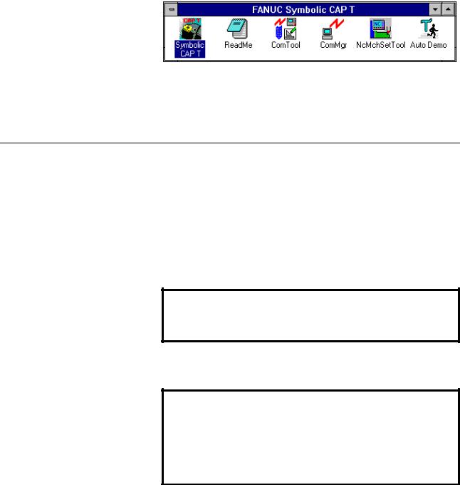
1. SETUP |
B-62824EN/02 |
group window has been added to Program Manager, together with an icon for Symbolic CAP T.
(12)When a message indicating the normal completion of setup appears, click OK.
(13)Upon the completion of setup, confirm that the FANUC Symbolic CAP T group window has been added to the Program Manager, together with an icon for Symbolic CAP T.
∙Icon registered
Prompts and/or messages not described above may appear depending on the
specific installation. In such cases, proceed as indicated on the window.
1.2.2 Setting up an optional module
When using an optional module, set it up once setup of the basic module has been completed. The procedure for setting up a typical optional module is described below. Note that some optional modules require the application of special procedures or precautions. Therefore, always refer to the corresponding operator's manual.
∙Preparation
(1)Check the name of the directory where the basic module has been installed.
NOTE
Optional modules must be stored into the same directory as that
where the basic module has been installed.
(2)After making sure that the computer and printer are switched off, attach the protectors for the basic module and optional module.
CAUTION
The computer and printer must be switched off while the protectors are being attached.
If the protector is attached or detached while the computer and printer are switched on, the computer, printer, or protector may be damaged.
-6-

B-62824EN/02 |
1. SETUP |
NOTE
If two or more optional modules are to be set up, the protectors for all those modules can be attached at this time. Protectors can be connected in series, in any order.
P r i n t e r C a b l e
P r o t e c t o r f o r B a s i c m o d u l e
Protector for Option module
P r i n t e r
(3)Switch on the computer and start Windows.
∙Setup procedure
(1)Perform setup in the same way as described in steps (1) to (7) for setting up the basic module.
NOTE
Insert the floppy disk labeled Disk#1 for the module to be set up.
As the installation destination directory, specify the directory where the basic module was installed.
(2)Upon the normal completion of setup, a prompt appears asking whether the protectors for the basic and optional modules are to be assembled into a single protector. Click Yes or No.
NOTE
Clicking Yes makes it possible to use Symbolic CAP T without attaching the protectors for the optional modules.
When No is clicked, the protectors for the basic module and each of the optional modules must be attached in series to enable the use of Symbolic CAP T.
Prompts and/or messages other than those described above may appear depending on the specific installation. In such cases, proceed as directed by the prompt.
-7-

1. SETUP |
B-62824EN/02 |
1.2.3 Reinstalling Symbolic CAP T
When reinstalling Symbolic CAP T in a directory where Symbolic CAP T has already been set up, you can select whether to register the data files again.
When you want to use the existing data, do not register the corresponding data when you are prompted to specify the data file to be set up.
When you want to reregister a data file, if the corresponding data file already exists in the target directory, you will be prompted to specify whether the previous data file is to be backed up. Click Yes or No, as required.
NOTE
When Yes is selected, the existing data is backed up to the BAK subdirectory under the Symbolic CAP T directory. The Symbolic CAP T directory will be rewritten with the standard data. If necessary, however, the previous data can be restored from the BAK subdirectory.
When No is selected, the existing data is overwritten with the standard data.
1.2.4 About the protector (Only for use with a personal computer)
The protector must be kept attached to enable the setup and use of Symbolic
CAP T. If it is detached, Symbolic CAP T will fail to run normally.
CAUTION
Both the computer and printer must be switched off before attempting to either attach or disconnect the protector.
If the protector is attached or detached while the computer and printer are switched on, the computer, printer, or protector may be damaged.
The protectors for other softwares can be gathered into the protector of the Symbolic CAP T basic module. It is not possible to assemble the protector of the Symbolic CAP T basic module into that of any other software.
If the protectors of other softwares are gathered into the Symbolic CAP T protector, the user need no longer be concerned with the other protectors as part of daily operation. These softwares can be made usable simply by attaching the Symbolic CAP T protector. Note that the individual protectors are required when the corresponding softwares are upgraded. So, they should be kept in a safe place.
If the protectors are not gathered into the Symbolic CAP T protector, they must be attached individually. They can be attached in any sequence.
-8-

B-62824EN/02 |
2. BASIC OPERATION |
2 BASIC OPERATION
2.1 Fundamentals
2.1.1 Starting Symbolic CAP T
Double-click the Symbolic CAP T icon.
2.1.2 Terminating Symbolic CAP T
Select File => Exit from the Symbolic CAP T menu.
2.1.3 Reading the latest information about Symbolic CAP T
Double-click the Read Me file icon. The Read Me file contains information relating to Symbolic CAP T that users should be aware of, together with information specific to the installed version. The information in the Read Me file does not appear in the operator's manual. It is imperative, therefore, that the user read the contents of this file.
2.1.4 Other Symbolic CAP T icons
There are several other executable icons for Symbolic CAP T. These correspond to the File Transmission Tool, File Transmission Manager, NC Machine Setting Tool, and Auto Demo.
-9-
2. BASIC OPERATION |
B-62824EN/02 |
The File Transmission Tool enables NC data exchange with an external device via a serial port. The File Transmission Manager is an application that manages the transmission schedule and performs the actual communication. Usually, it is not used independently.
The NC Machine Setting Tool is used to edit the contents of the management file that governs the output format of NC data. Using these tools together enables Symbolic CAP T to support a range of CNC units.
Auto Demo is an application that introduces the major functions of Symbolic
CAP T.
-10-
Loading...