


 Loading...
FANUC TURN MATE *
OPERATOR’S MANUAL
B-64254EN/06

•No part of this manual may be reproduced in any form.
•All specifications and designs are subject to change without notice.
The products in this manual are controlled based on Japan’s “Foreign Exchange and Foreign Trade Law”. The export from Japan may be subject to an export license by the government of Japan.
Further, re-export to another country may be subject to the license of the government of the country from where the product is re-exported. Furthermore, the product may also be controlled by re-export regulations of the United States government.
Should you wish to export or re-export these products, please contact FANUC for advice.
In this manual we have tried as much as possible to describe all the various matters.
However, we cannot describe all the matters which must not be done, or which cannot be done, because there are so many possibilities.
Therefore, matters which are not especially described as possible in this manual should be regarded as ”impossible”.

B-64254EN/06 |
SAFETY PRECAUTIONS |
SAFETY PRECAUTIONS
When using a machine equipped with the FANUC TURN MATE i, be sure to observe the following safety precautions.
s-1

SAFETY PRECAUTIONS |
B-64254EN/06 |
DEFINITION OF WARNING, CAUTION, AND NOTE
This manual includes safety precautions protecting the user and preventing damage to the machine. Precautions are classified into Warning and Caution according to the degree of the risk or the severity of damage.
Also, supplementary information is described as Note.
Read the Warning, Caution, and Note thoroughly before attempting to use the machine.
 WARNING
Applied when there is a danger to the user being injured or when there is a risk to the user, being injured, and the equipment, being damaged, if the warning statement is not followed up.
 CAUTION
Applied when there is a danger to the equipment being damaged, if the caution statement is not followed up.
NOTE
The Note is used to indicate supplementary information other than Warning and Caution.
Read this manual carefully, and store it in a safe place.
s-2

B-64254EN/06 |
SAFETY PRECAUTIONS |
GENERAL WARNINGS AND CAUTIONS
To ensure safety while using a machine featuring the TURN MATE i function, observe the following precautions:
 WARNING
1Confirm, on the screen, that the data has been entered correctly before proceeding to the next operation. Attempting operation with incorrect data may cause the tool to strike the workpiece or machine, possibly breaking the tool and/or machine and/or injuring the operator.
2When using constant surface speed control, set the maximum rotating speed of the spindle to a value that is allowed for the workpiece and workpiece holding unit. Otherwise, the workpiece or holding unit may be removed by centrifugal force damaging the machine or injuring the operator.
3Set all necessary parameters and data items before starting TURN MATE i operations. Note that if the cutting conditions are not suitable for the workpiece, the tool may be damaged and/or the operator may be injured.
4After creating a machining program using TURN
MATE i functions, do no run the machining program immediately on the machine . Before starting production machining, run the machine with no workpiece attached to the machine to make sure that the tool will not strike a workpiece or the machine. If the tool strikes the machine and/or workpiece, the tool and/or machine may be damaged, with possibility to injure the operator.
5Switching between inch and metric inputs does not convert the measurement units of data such as the workpiece origin offset, parameter, and current position. Before starting the machine, therefore, determine which measurement units are being used. Attempting to perform an operation with invalid data specified may damage the tool, the machine itself, the workpiece, or cause injury to the user.
 CAUTION
After pressing the power-on button, do not touch any keys on the keyboard until the initial screen appears. Some keys are used for maintenance or special operations such that pressing such a key may cause an unexpected operation.
s-3

SAFETY PRECAUTIONS |
B-64254EN/06 |
OVERVIEW OF THIS MANUAL
This manual describes the functions of "TURN MATE i" for the Series 0 i -TC/Mate-TC or Series 0 i -TD/Mate-TD.
For other functions, other than TURN MATE i, refer to the operator’s manual for the Series 0 i-TC/Mate-TC or Series 0 i -TD/Mate-TD. The specifications and features of TURN MATE i may differ from the specifications of the operator’s manual supplied by the machine tool builder. Be sure to read the manual provided by the machine tool builder.
The functions of the CNC machine tool system are determined not only by the CNC, but by the combination of the machine tool, the power magnetic circuit of the machine tool, the servo system, the CNC, and the operator’s panel.
It is impossible to cover all possible combinations of all functions, programming methods, and operations in a single manual.
This manual explains only the TURN MATE i operations provided for the CNC. For individual CNC machine tools, refer to applicable manuals supplied by the machine tool builders.
This manual explains as many detailed functions as possible. However, it is not possible to describe all the items which cannot be done or which the operator must not do. Therefore, please assume that functions not described in this manual cannot be performed.
Detailed information and special conditions are explained in notes. The readers may encounter new technical terms in the notes not previously defined or described. In this case, read this manual through first, and then review the details.
s-4

B-64254EN/06 |
TABLE OF CONTENTS |
TABLE OF CONTENTS
SAFETY PRECAUTIONS............................................................................ |
s-1 |
||
|
DEFINITION OF WARNING, CAUTION, AND NOTE ............................................. |
s-2 |
|
|
GENERAL WARNINGS AND CAUTIONS............................................................... |
s-3 |
|
|
OVERVIEW OF THIS MANUAL .............................................................................. |
s-4 |
|
I. WHAT’S TURN MATE i ? |
|
||
1 |
WHAT’S TURN MATE i ? ...................................................................... |
3 |
|
II. BASIC SCREEN AND OPERATIONS |
|
||
1 |
BASE SCREEN....................................................................................... |
7 |
|
2 |
BASIC SCREEN OPERATIONS........................................................... |
11 |
|
|
2.1 |
BUTTON OPERATION................................................................................ |
12 |
|
2.2 |
CURSOR OPERATION ............................................................................... |
13 |
|
2.3 |
TAB OPERATION........................................................................................ |
13 |
|
2.4 |
CALCULATOR OPERATION....................................................................... |
14 |
3 |
SETTING OF COORDINATE SYSTEM ................................................ |
17 |
|
4 |
SETTING OF SPINDLE INFORMATION .............................................. |
20 |
|
|
4.1 |
SETTING OF SPINDLE SPEED.................................................................. |
21 |
|
4.2 |
SETTING OF SURFACE SPEED ................................................................ |
22 |
|
4.3 |
SETTING OF GEAR NUMBER.................................................................... |
23 |
|
4.4 |
SETTING OF SPINDLE SPEED USING BUTTON ON MACHINE |
|
|
|
OPERATOR'S PANEL................................................................................. |
24 |
5 |
SETTING OF TOOL INFORMATION .................................................... |
25 |
|
|
5.1 |
TOOL SELECTION...................................................................................... |
26 |
|
5.2 |
INPUT OF TOOL OFFSET .......................................................................... |
27 |
|
|
5.2.1 Direct Input of Tool Offset..................................................................................... |
27 |
|
|
5.2.2 Measurement of Tool Offset .................................................................................. |
30 |
6 |
ALARM CHECK .................................................................................... |
33 |
|
III. MANUAL CUTTING |
|
||
1 |
MANUAL CUTTING .............................................................................. |
37 |
|
2 |
MANUAL CUTTING IN LIMITED AREA ............................................... |
40 |
|
c-1

TABLE OF CONTENTS B-64254EN/06
IV. CUTTING CYCLE |
|
|||
1 |
OUTLINE............................................................................................... |
|
47 |
|
|
1.1 |
WHAT’S CUTTING CYCLE ? ...................................................................... |
48 |
|
|
1.2 |
CUTTING METHODS.................................................................................. |
49 |
|
2 |
OPERATION |
......................................................................................... |
51 |
|
|
2.1 |
WORKFLOW ............................................................................................... |
52 |
|
|
2.2 |
SETTING THE FEEDRATE......................................................................... |
54 |
|
|
2.3 |
CREATING A NEW CUTTING CYCLE........................................................ |
55 |
|
|
2.4 |
EDITING A CUTTING CYCLE..................................................................... |
58 |
|
|
2.5 |
SELECTING A CUTTING CYCLE ............................................................... |
59 |
|
|
2.6 |
DELETING A CUTTING CYCLE.................................................................. |
61 |
|
|
2.7 |
NOTES |
........................................................................................................ |
63 |
|
|
2.7.1 |
Inhibition of Operation........................................................................................... |
63 |
|
|
2.7.2 Manual Intervention during Cutting Cycles........................................................... |
63 |
|
|
|
2.7.3 Tool Nose Radius Compensation ........................................................................... |
63 |
|
3 |
FACE CYCLE........................................................................................ |
64 |
||
|
3.1 |
OUTLINE ..................................................................................................... |
65 |
|
|
3.2 |
TOOL CUTTING MOTIONS ........................................................................ |
66 |
|
|
3.3 |
INPUT DATA ............................................................................................... |
69 |
|
4 |
CHAMFER CYCLE................................................................................ |
71 |
||
|
4.1 |
OUTLINE ..................................................................................................... |
72 |
|
|
4.2 |
TOOL CUTTING MOTIONS ........................................................................ |
74 |
|
|
4.3 |
INPUT DATA ............................................................................................... |
81 |
|
5 |
RECTANGULAR CYCLE...................................................................... |
82 |
||
|
5.1 |
OUTLINE ..................................................................................................... |
83 |
|
|
5.2 |
TOOL CUTTING MOTIONS ........................................................................ |
85 |
|
|
|
5.2.1 |
Rough Cutting Motions.......................................................................................... |
85 |
|
|
5.2.2 |
Finish Cutting Motions........................................................................................... |
93 |
|
5.3 |
INPUT DATA ............................................................................................... |
98 |
|
6 |
TAPER CYCLE ................................................................................... |
100 |
||
|
6.1 |
OUTLINE ................................................................................................... |
101 |
|
|
6.2 |
TOOL CUTTING MOTIONS ...................................................................... |
103 |
|
|
|
6.2.1 |
Rough Cutting Motions........................................................................................ |
103 |
|
|
6.2.2 |
Finish Cutting Motions......................................................................................... |
111 |
|
6.3 |
INPUT DATA ............................................................................................. |
116 |
|
c-2

B-64254EN/06 TABLE OF CONTENTS
7 RADIUS CYCLE.................................................................................. |
118 |
||
7.1 |
OUTLINE ................................................................................................... |
119 |
|
7.2 |
TOOL CUTTING MOTIONS ...................................................................... |
121 |
|
|
7.2.1 |
Rough Cutting Motions........................................................................................ |
121 |
|
7.2.2 |
Finish Cutting Motions......................................................................................... |
121 |
7.3 |
INPUT DATA ............................................................................................. |
122 |
|
8 FREE FIGURE CYCLE........................................................................ |
124 |
||
8.1 |
OUTLINE ................................................................................................... |
125 |
|
8.2 |
TOOL CUTTING MOTIONS ...................................................................... |
126 |
|
|
8.2.1 |
Rough Cutting Motions........................................................................................ |
126 |
|
8.2.2 |
Finish Cutting Motions......................................................................................... |
126 |
8.3 |
INPUT DATA ............................................................................................. |
127 |
|
|
8.3.1 Details of Input Data ............................................................................................ |
127 |
|
|
8.3.2 Free Figure Input Data Screen.............................................................................. |
129 |
|
|
8.3.3 Creating New Free Figure .................................................................................... |
134 |
|
8.4 |
NOTES |
...................................................................................................... |
137 |
|
8.4.1 |
Creation of Figure ................................................................................................ |
137 |
|
8.4.2 Cutting Cycle with Manual In-Feeding................................................................ |
138 |
|
|
8.4.3 |
Pocket Figure Operation....................................................................................... |
139 |
9 DRILL CYCLE ..................................................................................... |
140 |
|
9.1 |
OUTLINE ................................................................................................... |
141 |
9.2 |
TOOL CUTTING MOTIONS ...................................................................... |
142 |
9.3 |
INPUT DATA ............................................................................................. |
148 |
10 TAP CYCLE ........................................................................................ |
150 |
|
10.1 |
OUTLINE ................................................................................................... |
151 |
10.2 |
TOOL CUTTING MOTIONS ...................................................................... |
152 |
10.3 |
INPUT DATA ............................................................................................. |
156 |
11 GROOVE CYCLE................................................................................ |
157 |
||
11.1 |
OUTLINE ................................................................................................... |
158 |
|
11.2 |
TOOL CUTTING MOTIONS ...................................................................... |
160 |
|
|
11.2.1 |
Rough Cutting Motions........................................................................................ |
160 |
|
11.2.2 |
Finish Cutting Motions......................................................................................... |
163 |
11.3 |
INPUT DATA ............................................................................................. |
167 |
|
12 THREAD CYCLE................................................................................. |
169 |
||
12.1 |
OUTLINE ................................................................................................... |
170 |
|
12.2 |
TOOL CUTTING MOTIONS ...................................................................... |
171 |
|
|
12.2.1 |
Outer Thread Cycle .............................................................................................. |
171 |
|
12.2.2 |
Inner Thread Cycle............................................................................................... |
173 |
|
12.2.3 |
Cutting Methods................................................................................................... |
175 |
12.3 |
INPUT DATA ............................................................................................. |
180 |
|
c-3

TABLE OF CONTENTS B-64254EN/06
13 THREAD REPAIR CYCLE .................................................................. |
182 |
|
13.1 |
OUTLINE ................................................................................................... |
183 |
13.2 |
TOOL CUTTING MOTIONS ...................................................................... |
184 |
13.3 |
INPUT DATA ............................................................................................. |
185 |
V. SEQUENTIAL EXECUTION OF CUTTING CYCLES |
|
|
1 |
OVERVIEW ......................................................................................... |
191 |
|
2 |
CUTTING MOTIONS ........................................................................... |
192 |
|
3 |
OPERATIONS ..................................................................................... |
194 |
|
|
3.1 |
OPERATION PROCEDURE...................................................................... |
195 |
|
3.2 |
PROCESS CREATION.............................................................................. |
202 |
|
3.3 |
PROCESS ALTERATION.......................................................................... |
204 |
|
3.4 |
PROCESS DELETION .............................................................................. |
205 |
VI. CONVERSION OF CUTTING CYCLE TO NC STATEMENT |
|
||
(OPTION) |
|
||
1 |
OVERVIEW ......................................................................................... |
209 |
|
2 |
OPERATIONS ..................................................................................... |
210 |
|
|
2.1 |
OPERATIONS ON SINGLE EXECUTION SCREEN ................................. |
211 |
|
2.2 |
OPERATIONS ON SEQUENTIAL EXECUTION SCREEN........................ |
214 |
3 |
NOTES ................................................................................................ |
217 |
|
VII. DATA INPUT/OUTPUT USING MEMORY CARD |
|
||
1 |
OVERVIEW ......................................................................................... |
221 |
|
2 |
CUTTING CYCLE DATA INPUT/OUTPUT ......................................... |
222 |
|
|
2.1 |
CUTTING CYCLE DATA INPUT................................................................ |
223 |
|
2.2 |
CUTTING CYCLE DATA OUTPUT............................................................ |
227 |
3 |
PROGRAM INPUT/OUTPUT............................................................... |
231 |
|
|
3.1 |
PROGRAM INPUT .................................................................................... |
232 |
|
3.2 |
PROGRAM OUTPUT ................................................................................ |
236 |
4 |
MEMORY CARD FORMATTING ........................................................ |
238 |
|
VIII. DATA SETTING |
|
||
1 |
OVERVIEW ......................................................................................... |
241 |
|
2 |
LANGUAGE SETTING........................................................................ |
242 |
|
3 |
INCH/METRIC SETTING..................................................................... |
243 |
|
4 |
FINISHING AMOUNT SETTING ......................................................... |
244 |
|
c-4
B-64254EN/06 |
|
|
TABLE OF CONTENTS |
|
IX. MDI KEY OPERATION FUNCTION (OPTION) |
|
|||
1 |
OVERVIEW |
......................................................................................... |
247 |
|
2 SINGLE EXECUTION ............................SCREEN (BASE SCREEN) |
248 |
|||
3 CUTTING CYCLE ..........................................SELECTION SCREEN |
249 |
|||
4 CYCLE INPUT ..........................................................DATA SCREEN |
250 |
|||
5 FREE FIGURE ..............................................INPUT DATA SCREEN |
251 |
|||
6 |
SEQUENTIAL ................................................EXECUTION SCREEN |
253 |
||
APPENDIX |
|
|
||
A |
WARNINGS......................................................................................... |
|
257 |
|
B |
ALARMS ............................................................................................. |
|
260 |
|
|
B.1 |
ALARMS ......................................................COMMON TO ALL CYCLES |
261 |
|
|
B.2 |
RECTANGULAR, TAPER, RADIUS, FREE FIGURE AND FACE CYCLES |
||
|
|
................................................................................................................... |
|
261 |
|
B.3 |
THREAD .......................................................................................CYCLE |
261 |
|
|
B.4 |
GROOVE ......................................................................................CYCLE |
262 |
|
|
B.5 |
HOLE ............................................................................................CYCLE |
262 |
|
|
B.6 |
SEQUENTIAL ......................................................................EXECUTION |
262 |
|
C |
PARAMETERS.................................................................................... |
263 |
||
|
C.1 PARAMETERS ..............................RELATED TO BASIC OPERATIONS |
264 |
||
|
C.2 PARAMETERS ..................................RELATED TO COLOR PALETTES |
268 |
||
|
|
C.2.1 ...........................................Setting Related to Color Palettes for Screen Display |
268 |
|
|
|
C.2.2 ...............................................Setting Related to Color Palettes for Icon Display |
271 |
|
|
|
C.2.3 .......................................Setting Related to Color Palettes for Guidance Display |
273 |
|
|
C.3 PARAMETERS ..................................RELATED TO CUTTING CYCLES |
275 |
||
|
|
C.3.1 ......................................................................Parameters Common to All Cycles |
275 |
|
|
|
C.3.2 ....................................................................................................... |
Turning Cycle |
277 |
|
|
C.3.3 ........................................................................................................ |
Thread Cycle |
278 |
|
|
C.3.4 ........................................................................................................ |
Groove Cycle |
279 |
|
|
C.3.5 ............................................................................................................ |
Hole Cycle |
280 |
APPENDIX (FOR MACHINE TOOL BUILDER) |
|
|||
A |
LADDER PROGRAM ......................................................CREATION |
283 |
||
|
A.1 |
TURN ..............................................MATE i SCREEN SWITCH SIGNAL |
284 |
|
|
A.2 |
MODE ........................................................................................CHANGE |
285 |
|
|
A.3 |
CYCLE ..........................................................................................START |
286 |
|
|
A.4 |
REVERSE .............................................................................TAP CYCLE |
288 |
|
|
A.5 |
SPINDLE ......................................................................................SPEED |
291 |
|
c-5

TABLE OF CONTENTS |
B-64254EN/06 |
|
B LINKING MACRO CREATED BY MACHINE TOOL BUILDER WITH |
||
TURN MATE i MACRO...................................................................... |
293 |
|
B.1 |
LINKING MACRO PROGRAM................................................................... |
294 |
|
B.1.1 In Case of 0i-TC/Mate-TC ................................................................................... |
294 |
|
B.1.2 In Case of 0i-TD/Mate-TD................................................................................... |
295 |
B.2 |
NOTES ...................................................................................................... |
295 |
C PARAMETER SETTING...................................................................... |
296 |
|
C.1 PARAMETERS NEEDED ON NC SIDE .................................................... |
297 |
|
C.2 |
PARAMETERS NEEDED ON TURN MATE i SIDE.................................. |
299 |
c-6
I. WHAT’S TURN MATE i ?
|
|
|
1.OVERVIEW OF |
|
|
B-64254EN/06 |
OVERVIEW OF TURN MATE i |
TURN MATE i |
|
|
1 |
WHAT’S TURN MATE i ? |
|
|
TURN MATE i provides integrated operation guidance functions for CNC lathes that are designed to enable the operator to perform turning without the need to create an NC program.
TURN MATE i screen
It has the following main features:
(1)Integrated display of all information necessary for operation on a single screen
All information necessary for operation is integrated on a single screen, so that the operator need not switch between screens.
(2)Simple screen operation using the touch panel or cursor keys
By touching an item displayed on the screen or selecting it using cursor keys, the operator can jump to a related operation screen. This allows intuitive operation.
(3)Easily operable even by operators inexperienced in CNCs
It is not necessary to create machining programs in ISO code format. By entering data in accordance with the guidance drawing displayed on the screen, it is possible to perform turning with ease.
(4)Support of cutting methods for general-purpose lathes
It supports two types of cutting methods, manual cutting and cutting cycles, often used with general-purpose lathes.
-3 -

1. OVERVIEW OF
TURN MATE i OVERVIEW OF TURN MATE i B-64254EN/06
(a)Manual cutting
It is possible to move the tool freely to perform cutting, using the handle or the JOG switch. It is also possible to move the tool in a limited area.
(b)Cutting cycles
A cutting cycle is a series of prescribed cutting motions collected together. By starting the start button, the series of cutting motions is automatically executed.
Execution
(5) Various cutting cycles containing free figures are available. It provides all cutting cycles necessary for lathes.
The following cutting cycles are available:
(a)Rough cutting cycle (pattern figure, free figure)
(b)Finish cutting cycle (pattern figure, free figure)
(c)Groove cycle (pattern figure, free figure)
(d)Thread cycle (general-purpose screw)
(e)Re-thread cycle (general-purpose screw)
(f)Hole cycle (drill, tap)
- 4 -
II. BASIC SCREEN AND OPERATIONS

B-64254EN/06 |
BASIC SCREEN AND OPERATIONS |
1.BASE SCREEN |
1 BASE SCREEN
TURN MATE i has integrated all information necessary for operation on a single screen. This integrated screen is called the Base Screen.
|
|
|
(2) Spindle speed (5) Machine status |
||||||||||
|
|
|
|
|
|
|
|
|
|
|
(3) |
||
|
|
|
|
|
|
|
|
|
|
|
|||
|
|
|
|
|
|
|
|
|
|
||||
|
|
|
|
|
|
|
|
|
|
||||
|
|
|
|
|
|
|
|
|
|||||
(1) |
|
|
|
|
|
|
|
|
|
|
|
|
Feedrate |
|
|
|
|
|
|
|
|
|
|
|
|
|
|
|
|
|
|
|
|
|
|
|
|
|
|
|
|
Present |
|
|
|
|
|
|
|
|
|
|
|
|
|
|
|
|
|
|
|
|
|
|
|
|
|
||
position |
|
|
|
|
|
|
|
|
|
|
|
(4) |
|
|
|
|
|
|
|
|
|
|
|
|
|
||
|
|
|
|
|
|
|
|
|
|
|
|
|
Tool number |
|
|
|
|
|
|
|
|
|
|
|
|||
(6) |
|
|
|
|
|
|
|
(7) |
|
|
|
||||||
|
|
|
|
|
|
|||
Guidance |
|
|
|
|
|
|
Cutting |
|
drawing for |
|
|
|
|
|
|
cycle data |
|
cutting cycle |
|
|
|
|
|
|
|
|
|
|
|
|
|
|
|
|
|
(8)

 (9)
(9)
Alarm |
|
|
|
|
|
|
|
|
|
|
|
|
Cutting cycle |
|
|
|
|
|
|
|
|
|
|
|
|||
message |
|
|
|
|
|
|
|
|
|
|
|
call number |
|
|
|
|
|
||||||||||
|
|
|
|
|
|||||||||
|
(10) Manual cutting screen (11) Setting screen |
(12) Cutting cycle call |
|||||||||||
|
|
|
|
Base Screen |
|
|
|
|
|||||
The Base Screen consists of nine sections and four soft keys.
In each section, information display and operation functions are integrated together. Either by touching a section on the tough panel or by moving the focus to a section using cursor keys as appropriate and pressing the [INPUT] key, the operator can jump to the related operation screen.
- 7 -
1.BASE SCREEN |
BASIC SCREEN AND OPERATIONS |
B-64254EN/06 |
Each of the sections and soft keys is described below.
(1)Present position section
In this section, the present position (absolute coordinates) and the load ratio (load meter) of the servo axis are displayed. Touching this section causes a jump to the workpiece coordinate system setting screen.
"Workpiece coordinate system setting screen": Screen for setting the workpiece coordinate system.
(2)Spindle speed section
In this section, the actual spindle rotation speed (rpm (min-1)), the commanded spindle speed (S_set), and the spindle load ratio (load meter) are displayed. In addition, the following states are represented by icons:
(a)Spindle direction (CW or CCW)
(b)Constant surface speed control (enabled or disabled) Touching this section causes a jump to the spindle speed setting screen.
"Spindle speed setting screen":
Screen for setting a spindle speed, turning constant surface speed control ON/FF, and setting a gear number.
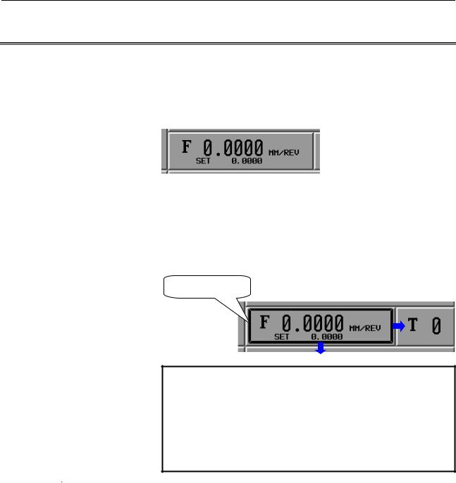
(3)Feedrate section
In this section, the actual feedrate and the commanded feedrate (F_set) are displayed. Touching this section causes a jump to the feedrate setting screen.
"Feedrate setting screen":
Screen for setting the feedrate used in a cutting cycle.
(4)Tool number section
In this section, the currently selected tool number is displayed. Touching this section causes a jump to the tool selection screen.
"Tool selection screen": Screen for selecting the tool to use and setting tool data (offset value, radius of the tool nose, and virtual tool tip)
(5)Machine status section
In this section, the machine status is displayed.
MTN |
: The tool is moving along at least one axis. |
|
(The CNC is in MEM mode.) |
ALM |
: A CNC or machine alarm has been generated. |
EMG |
: Emergency stop state |
RESET |
: Reset state |
HOLD |
: Automatic operation suspend |
STOP |
: Automatic operation stop |
FIN |
: Miscellaneous function under execution |
MSG |
: An operator message has been generated. |
- 8 -
B-64254EN/06 |
BASIC SCREEN AND OPERATIONS |
1.BASE SCREEN |
(6)Guidance drawing for cutting cycle section
In this section, the guidance drawing for the currently selected cutting cycle is displayed. Touching this section causes a jump to the cutting cycle selection screen.
"Cutting cycle selection screen":
Screen for selecting the cutting cycle to create.
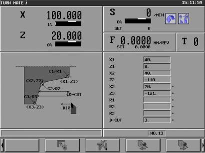
(7)Cutting cycle data section
In this section, the currently selected cutting cycle data (NOTE) is displayed. Touching this section causes a jump to the cutting cycle input screen.
"Cutting cycle input screen":
Screen for editing the input data for the currently selected cutting cycle
NOTE
By enabling the optional function and parameter below, it is possible to display cutting methods (R+F, DIR, and XA/ZA) and cutting conditions (T, CSS, S, and T) as additional cutting cycle data.
•Optional function: Expansion of Machining
Cycle
•Parameter: Bit 4 (DID) of parameter No. 9103
= 1
Screen example)
(8)Alarm section
In this section, a P/S alarm (38 characters in length) is displayed. Touching this section causes a jump to the alarm screen.
"Alarm screen":
Screen for displaying all NC alarm messages and operator messages.
- 9 -
1.BASE SCREEN |
BASIC SCREEN AND OPERATIONS |
B-64254EN/06 |
(9)Cutting cycle call number section
TURN MATE i provides 40 areas for storing cutting cycle data. The serial numbers for these storage areas are used as cutting cycle call numbers. In this section, the currently selected cutting cycle call number is displayed. Touching this section causes a jump to the cutting cycle call selection screen.
"Cutting cycle call selection screen":
Screen for selecting and deleting cutting cycles.
(10)Manual cutting screen switching soft key: [HANDLE]
This soft key causes a switch to the manual cutting screen.
"Manual cutting screen": |
Screen for performing manual |
cutting. |
|
(11)Setting screen switching soft key: [SETTING]
This soft key causes a switch to the setting screen. "Setting screen":
Screen for selecting a language, switching between inch and metric systems, and setting a default finishing amount.
(12)Cutting cycle call soft keys: [←][→]
Touching the [←] soft key causes selection of the cutting cycle call number equal to the currently selected cutting cycle call number minus 1.
Touching the [→] soft key causes selection of the cutting cycle call number equal to the currently selected cutting cycle call number plus 1.
- 10 -
|
|
|
2.BASIC SCREEN |
|
|
B-64254EN/06 |
BASIC SCREEN AND OPERATIONS |
OPERATIONS |
|
|
2 |
BASIC SCREEN OPERATIONS |
|
|
This chapter consists of the sections below.
2.1 |
BUTTON OPERATION ............................................................ |
12 |
2.2 |
CURSOR OPERATION............................................................. |
13 |
2.3 |
TAB OPERATION..................................................................... |
13 |
2.4 |
CALCULATOR OPERATION.................................................. |
14 |
- 11 -
2. BASIC SCREEN
OPERATIONS BASIC SCREEN AND OPERATIONS B-64254EN/06
2.1 BUTTON OPERATION
A section in which information display and operation functions are integrated together appear raised as shown below (NOTE 1). (A section that does not appear raised provides information display functions only.)
Such a raised section is called a button.
There are two methods to button operation:
(1)Touch the desired section on the touch panel.
(2)Move the focus (button cursor) to the desired section using the cursor keys (↑, ↓, ←, and →) as appropriate and press the
[INPUT] key (NOTE 2).
Either of the above methods causes a jump to the related operation screen.
Button cursor
NOTE
1To make a button appear more pronouncedly raised, change the color settings on the color palette, using parameters Nos. 9156 and 9162.
2The method of moving the focus to a section using cursor keys requires the MDI key operation function (option). For details, see Part IX, "MDI Key Operation Function".
- 12 -
|
|
|
2.BASIC SCREEN |
|
|
B-64254EN/06 |
BASIC SCREEN AND OPERATIONS |
OPERATIONS |
|
|
2.2 |
CURSOR OPERATION |
|
|
|
|
|
|
|
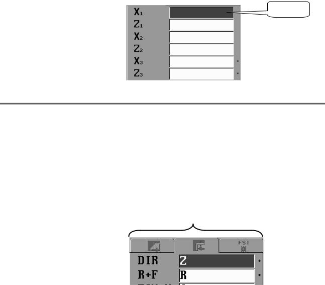
The cursor can be moved between edit boxes, using the cursor key (↑ and ↓). The edit box on which the cursor is positioned is displayed gray (blue on a color LCD).
By entering data in one edit box, the cursor is automatically moved to the next edit box.
Cursor
2.3 TAB OPERATION
On a setting screen such as the cutting cycle input screen, multiple tabs are displayed on top of the data in an edit box.
By selecting one of these tabs, it is possible to switch to the corresponding one of the multiple edit boxes hidden behind.
There are two methods to tab selection:
(1)Touch a tab on the touch panel.
(2)Press the cursor key (← and →) as appropriate.
Either of the methods above causes the edit box of the selected tab to appear.
Tabs
- 13 -
2. BASIC SCREEN
OPERATIONS BASIC SCREEN AND OPERATIONS B-64254EN/06
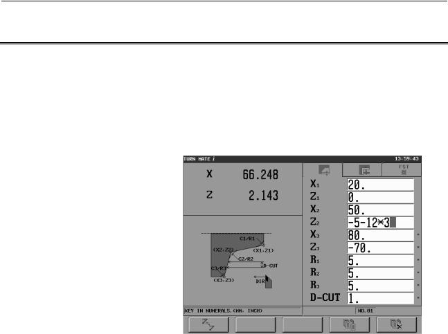
2.4 CALCULATOR OPERATION
Functions are provided whereby when numeric data is input, expressions for arithmetic operations, trigonometric functions, square root calculations, and so forth can be input for calculation.
These functions can be used in the input of cycle data, input of free figure data, and setting of various data (such as workpiece coordinate system data).
Input example)
Cutting cycle input screen example
The following describes each calculation operation.
•Arithmetic operations
(addition, subtraction, multiplication, and division)
Arithmetic operations are performed by using the key operations described below. The result of a calculation is displayed at the cursor position of input data.
(1)Addition : 100.+200. [INPUT]
(2)Subtraction : 100.-200. [INPUT]
(3)Multiplication : 100.*200. [INPUT]
(4)Division : 100./200. [INPUT]
- 14 -
|
|
2.BASIC SCREEN |
B-64254EN/06 |
BASIC SCREEN AND OPERATIONS |
OPERATIONS |
•Trigonometric functions
(sine, cosine, tangent, arcsine, arccosine, arctangent)
Trigonometric function calculations are performed by using the key operations described below. The result of a calculation is displayed at the cursor position of input data.
(1)Sine : SIN[45] [INPUT]
(2)Cosine : COS[45] [INPUT]
(3)Tangent : TAN[45] [INPUT]
(4)Arcsine : ASIN[0.5] [INPUT]
(5)Arccosine : ACOS[0.5] [INPUT]
(6)Arctangent : ATAN[20,2] [INPUT]
(Note that for an arctangent calculation, a special format using two arguments is required. Enter data according to the format ATAN[a,b]. arctan(a/b) is calculated.)
For a calculation, brackets ( [ ] ) are required at all times.
•Square root
A square root calculation is performed by using the key operations described below. The result of a calculation is displayed at the cursor position of input data.
(1)Square root : SQRT[45] [INPUT]
For a calculation, brackets ( [ ] ) are required at all times.
•Exponential functions
Exponential function calculations are performed by using the key operations described below. The result of a calculation is displayed at the cursor position of input data.
(1)Exponential function 1 (An exponential function of e = 2.718... can be calculated.) :
EXP[4] [INPUT]
(2)Exponential function 2 ("a" raised to the power of "b" can be calculated.) :
PWR[4,3] [INPUT]
(Note that for a calculation of exponential function 2, a special format using two arguments is required. Enter data according to the format PWR[a,b]. "a" raised to the power of "b" is calculated.)
For a calculation, brackets ( [ ] ) are required at all times.
•Logarithmic functions
(common logarithm, natural logarithm)
Logarithmic function calculations are performed by using the key operations described below. The result of a calculation is displayed at the cursor position of input data.
(1)Common logarithm : LOG[45] [INPUT]
(2)Natural logarithm : LN[45] [INPUT]
For a calculation, brackets ( [ ] ) are required at all times.
- 15 -

2. BASIC SCREEN
OPERATIONS BASIC SCREEN AND OPERATIONS B-64254EN/06
•Absolute value
An absolute value calculation is performed by using the key operations described below. The result of a calculation is displayed at the cursor position of input data.
(1)Absolute value : ABS[-45] [INPUT]
For a calculation, brackets ( [ ] ) are required at all times.
•Rounding
Rounding operations are performed by using the key operations described below. The result of a calculation is displayed at the cursor position of input data.
(1)Rounding 1 (rounding off to an integer) :
RND[1.234] [INPUT]
(2)Rounding 2 (rounding off "a" to the decimal places specified by "b") :
RND2[1.267,0.01] [INPUT]
(Note that for a calculation of rounding 2, a special format using two arguments is required. Enter data according to the format RND[a,b]. The value of "a" is rounded off to the decimal places specified by "b". As "b", do not specify a value other than 1, 0.1, 0.01, and so forth.)
For a calculation, brackets ( [ ] ) are required at all times.
•Discarding
This operation discards all decimal places. A discarding operation is performed by using the key operations described below. The result of a calculation is displayed at the cursor position of input data.
(1)Discarding : FIX[1.234] [INPUT]
For a calculation, brackets ( [ ] ) are required at all times.
•Circle ratio
A circle ratio calculation is performed by using the key operations described below. The circle ratio 3.14... is indicated.
(1)Circle ratio : PAI [INPUT]
- 16 -
|
|
3.SETTING OF |
B-64254EN/06 |
BASIC SCREEN AND OPERATIONS |
COORDINATE SYSTEM |
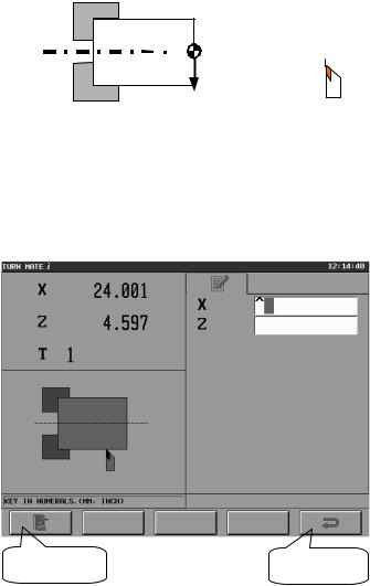
3 SETTING OF COORDINATE SYSTEM
TURN MATE i assumes the coordinate system shown below.
It is necessary to set the workpiece coordinate system before operating the machine.
-X 

 +Z
+Z 
-Z 
+X
Push the present position screen area on the Base Screen to display the workpiece coordinate system setting screen, shown below. The present position and the active tool number are displayed on the upper left side of the screen. On the right side of the screen, a data input area is displayed, and on the bottom left side of the screen, the guidance drawing for input items is displayed.
[SET] key |
[RET] key |
Workpiece coordinate system setting screen (X coordinate)
- 17 -
3. SETTING OF
COORDINATE SYSTEM BASIC SCREEN AND OPERATIONS B-64254EN/06
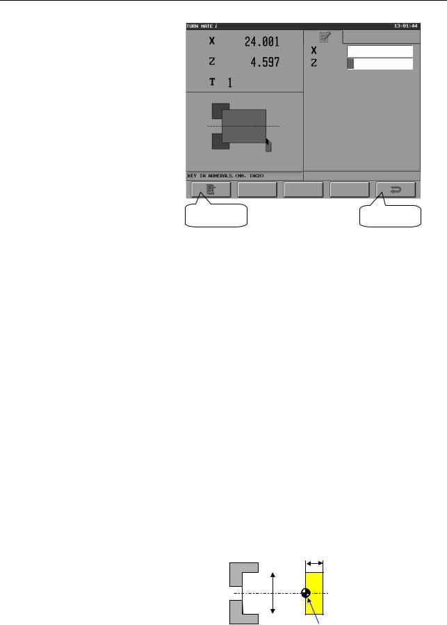
[SET] key |
[RET] key |
Workpiece coordinate system setting screen (Z coordinate)
It is possible to decide on the origin of the workpiece coordinate system by following the procedure described below.
<Measurement of X coordinate>
(1)To determine a standard plane, cut the side at a low feedrate, using the handle.
(2)Retract the tool along the Z-axis only, not moving it along the X-axis, then stop the spindle.
(3)Measure the diameter of the workpiece, assume this value as the input value for X, and set it for the input item X.
(4)Push the [SET] key.
(5)The X coordinate of the present position shown on the upper left side of the screen is replaced with the value entered in <3>.
<Measurement of Z coordinate>
(1)Bring the tool in contact with the workpiece face side, and measure the Z coordinate.
(2)Set the desired value for the input item Z.
(3)Push the [SET] key.
(4)The Z coordinate of the present position shown on the upper left side of the screen is replaced with the value entered in <2>.
Example)
If deciding on the origin of the workpiece coordinate system as shown in the figure below
10
φ 40
Workpiece origin
- 18 -
Loading...