


DES-3010FL

D-Link ™ DES-3010F / DES-3010FL / DES-3010G / DES-3018 / DES-3026
Layer 2 Managed 8/16/24-Port 10/100Mbps Fast Ethernet
Switch with Optional Slots
Release IV
Manual

_________________________________________________________________________________
Information in this document is subject to change without notice.
© 2007 D-Link Corporation. All rights reserved.
Reproduction in any manner whatsoever without the written permission of D-Link Computer Corporation is strictly forbidden.
Trademarks used in this text: D-Link and the D-LINK logo are trademarks of D-Link Computer Corporation; Microsoft and Windows are registered trademarks of
Microsoft Corporation.
Other trademarks and trade names may be used in this document to refer to either the entities claiming the marks and names or their products. D-Link Computer
Corporation disclaims any proprietary interest in trademarks and trade names other than its own.
May 2007 P/N 651ES3026045G

Table of Contents
Preface........................................................................................................................................................... viii
Intended Readers........................................................................................................................................................................... ix
Typographical Conventions ...........................................................................................................................................................................ix
Notes, Notices, and Cautions ........................................................................................................................................................ ix
Safety Instructions.......................................................................................................................................................................... x
Safety Cautions ...............................................................................................................................................................................................x
General Precautions for Rack-Mountable Products .......................................................................................................................................xi
Protecting Against Electrostatic Discharge.................................................................................................................................................. xii
Introduction...................................................................................................................................................... 1
Switch Description......................................................................................................................................................................... 1
Features........................................................................................................................................................................................................... 1
Ethernet Technology ...................................................................................................................................................................... 3
Fast Ethernet ...................................................................................................................................................................................................3
Gigabit Ethernet Technology ..........................................................................................................................................................................3
Switching Technology ....................................................................................................................................................................................3
Front-Panel Components and LED Indicators.................................................................................................................................................4
Rear Panel Description....................................................................................................................................................................................6
Side Panel Description....................................................................................................................................................................................6
Installation........................................................................................................................................................ 7
Package Contents............................................................................................................................................................................................7
Before You Connect to the Network...............................................................................................................................................................7
Installing the Switch without the Rack............................................................................................................................................................8
Installing the Switch in a Rack........................................................................................................................................................................8
Mounting the Switch in a Standard 19" Rack............................................................................................................................................8
Power On...................................................................................................................................................................................................8
The Optional Modules ....................................................................................................................................................................................9
Connecting the Switch ...................................................................................................................................12
Switch to End Node ......................................................................................................................................................................................12
Switch to Hub or Switch...............................................................................................................................................................................13
The DES-3010F/FL/G, DES-3018 or DES-3026 as a Network Backbone..............................................................................................14
Introduction to Switch Management ...........................................................................................................15
Management Options ................................................................................................................................................................... 15
Web-based Management Interface................................................................................................................................................................15
SNMP-Based Management...........................................................................................................................................................................15
Command Line Console Interface through the Serial Port............................................................................................................................15
Connecting the Console Port (RS-232 DCE)...........................................................................................................................................15
First Time Connecting to the Switch.............................................................................................................................................................17
Password Protection...................................................................................................................................................................................... 19
SNMP Settings..............................................................................................................................................................................................19
Traps........................................................................................................................................................................................................20
MIBs........................................................................................................................................................................................................20

IP Address Assignment................................................................................................................................................................................. 21
Connecting Devices to the Switch ................................................................................................................................................................22
Introduction to Web-based Switch Configuration .....................................................................................23
Introduction.................................................................................................................................................................................. 23
Logging on to the Web Manager...................................................................................................................................................................23
Web-based User Interface.............................................................................................................................................................................24
Areas of the User Interface ......................................................................................................................................................................24
Web Pages.....................................................................................................................................................................................................25
Administration ...............................................................................................................................................26
Device Information ...................................................................................................................................................................... 27
IP Address.................................................................................................................................................................................... 28
Setting the Switch's IP Address using the Console Interface...................................................................................................................29
Port Configuration........................................................................................................................................................................ 30
Port Settings.................................................................................................................................................................................................. 30
Port Description ........................................................................................................................................................................... 32
Port Err-Disabled ......................................................................................................................................................................... 33
User Accounts.............................................................................................................................................................................. 34
Admin and User Privileges......................................................................................................................................................................35
Port Mirroring .............................................................................................................................................................................. 36
System Log Settings..................................................................................................................................................................... 37
SNTP Settings.............................................................................................................................................................................. 39
Time Setting ............................................................................................................................................................................................39
Time Zone and DST ................................................................................................................................................................................40
MAC Notification Settings .......................................................................................................................................................... 42
TFTP Services...............................................................................................................................................................................................43
Ping Test ...................................................................................................................................................................................... 43
SNMP Manager..............................................................................................................................................44
SNMP Settings..............................................................................................................................................................................................44
SNMP Trap Settings .....................................................................................................................................................................................45
SNMP User Table.........................................................................................................................................................................................45
SNMP View Table........................................................................................................................................................................................ 47
SNMP Group Table ......................................................................................................................................................................................48
SNMP Community Table..............................................................................................................................................................................50
SNMP Host Table.........................................................................................................................................................................................51
SNMP Engine ID ..........................................................................................................................................................................................52
IP-MAC Binding.......................................................................................................................................................................... 53
IP-MAC Binding Port ................................................................................................................................................................................... 53
IP-MAC Binding Table.................................................................................................................................................................................54
IP-MAC Binding Blocked.............................................................................................................................................................................55
D-Link Single IP Management .................................................................................................................................................... 56
Single IP Management (SIM) Overview.......................................................................................................................................................56
SIM Using the Web Interface....................................................................................................................................................... 57
Topology...................................................................................................................................................................................... 58
Tool Tips...................................................................................................................................................................................... 60

Right Click....................................................................................................................................................................................................61
Group Icon...............................................................................................................................................................................................61
Commander Switch Icon .........................................................................................................................................................................61
Member Switch Icon................................................................................................................................................................................62
Candidate Switch Icon.............................................................................................................................................................................63
Menu Bar ......................................................................................................................................................................................................64
Group.......................................................................................................................................................................................................64
Device......................................................................................................................................................................................................64
View ........................................................................................................................................................................................................64
Firmware Upgrade ....................................................................................................................................................................... 65
Configuration File Backup/Restore.............................................................................................................................................. 65
Upload Log File ............................................................................................................................................................................................66
Forwarding & Filtering ................................................................................................................................................................ 67
Unicast Forwarding.......................................................................................................................................................................................67
Multicast Forwarding.................................................................................................................................................................................... 68
Multicast Filtering.........................................................................................................................................................................................69
SMTP Service .............................................................................................................................................................................. 70
SMTP Server Settings...................................................................................................................................................................................71
SMTP Service...............................................................................................................................................................................................72
L2 Features..................................................................................................................................................... 73
VLANs......................................................................................................................................................................................... 73
VLAN Description........................................................................................................................................................................................73
Notes about VLANs on the Switch..........................................................................................................................................................73
IEEE 802.1Q VLANs ...................................................................................................................................................................................73
802.1Q VLAN Tags.................................................................................................................................................................................74
Tagging and Untagging ...........................................................................................................................................................................75
Ingress Filtering.......................................................................................................................................................................................75
Default VLANs........................................................................................................................................................................................75
VLAN Segmentation ............................................................................................................................................................................... 76
VLAN and Trunk Groups ........................................................................................................................................................................76
Static VLAN Entry .......................................................................................................................................................................................77
Link Aggregation ......................................................................................................................................................................... 79
Understanding Port Trunk Groups...........................................................................................................................................................79
IGMP Snooping ........................................................................................................................................................................... 81
Static Router Ports Settings...........................................................................................................................................................................83
Spanning Tree .............................................................................................................................................................................. 84
802.1w Rapid Spanning Tree...................................................................................................................................................................84
Port Transition States...............................................................................................................................................................................84
Edge Port .................................................................................................................................................................................................84
P2P Port...................................................................................................................................................................................................84
802.1d and 802.1w Compatibility............................................................................................................................................................85
STP Bridge Global Settings ..........................................................................................................................................................................85
STP Port Settings..........................................................................................................................................................................................87
Loopback Detection ..................................................................................................................................................................... 89
CoS ..................................................................................................................................................................90

CoS............................................................................................................................................................................................... 90
IEEE 802.1p Priority.....................................................................................................................................................................................90
The Advantages of CoS ................................................................................................................................................................................91
Understanding CoS ....................................................................................................................................................................................... 92
Bandwidth Control........................................................................................................................................................................................ 93
802.1p Default Priority .................................................................................................................................................................................94
802.1p User Priority...................................................................................................................................................................................... 95
CoS Scheduling Mechanism ......................................................................................................................................................................... 95
CoS Output Scheduling.................................................................................................................................................................................96
Priority Settings ............................................................................................................................................................................................97
TOS Priority Settings....................................................................................................................................................................................98
DSCP Priority Settings..................................................................................................................................................................................99
Port Mapping Priority CoS..........................................................................................................................................................................100
MAC Priority Setting..................................................................................................................................................................................101
CPU Interface Filtering...............................................................................................................................102
CPU Interface Filtering State Settings ........................................................................................................................................................ 102
CPU Interface Filtering Table.....................................................................................................................................................................102
Security .........................................................................................................................................................113
Traffic Control ........................................................................................................................................................................... 113
Port Security............................................................................................................................................................................... 116
Port Lock Entries ....................................................................................................................................................................... 117
802.1X........................................................................................................................................................................................ 118
802.1x Port-Based and MAC-Based Access Control..................................................................................................................................118
Authentication Server ............................................................................................................................................................................ 119
Authenticator .........................................................................................................................................................................................119
Client .....................................................................................................................................................................................................120
Authentication Process ..........................................................................................................................................................................121
Understanding 802.1x Port-based and MAC-based Network Access Control ............................................................................................122
Port-Based Network Access Control...........................................................................................................................................................122
MAC-Based Network Access Control ........................................................................................................................................................ 123
802.1X Authenticator Settings....................................................................................................................................................................124
Local Users............................................................................................................................................................................................126
Port Capability....................................................................................................................................................................................... 126
Guest VLANs..............................................................................................................................................................................................127
Limitations Using the Guest VLAN ...................................................................................................................................................... 127
Guest VLAN...............................................................................................................................................................................................128
Initializing Ports for Port Based 802.1x.................................................................................................................................................129
Initializing Ports for MAC Based 802.1x ..............................................................................................................................................130
Reauthenticate Port(s) for Port Based 802.1x........................................................................................................................................130
Reauthenticate Port(s) for MAC-based 802.1x......................................................................................................................................131
RADIUS Server.....................................................................................................................................................................................132
Trusted Host............................................................................................................................................................................... 133
Traffic Segmentation.................................................................................................................................................................. 134
Monitoring.................................................................................................................................................... 136
CPU Utilization.......................................................................................................................................................................... 136

Port Utilization........................................................................................................................................................................... 137
Packets ....................................................................................................................................................................................... 138
Received (RX) ............................................................................................................................................................................................138
UMB Cast (RX) ..........................................................................................................................................................................................140
Transmitted (TX) ........................................................................................................................................................................................ 142
Errors.......................................................................................................................................................................................... 144
Received (RX) ............................................................................................................................................................................................144
Transmitted (TX) ........................................................................................................................................................................................ 146
Packet Size ................................................................................................................................................................................. 148
MAC Address ............................................................................................................................................................................ 150
Switch History Log .................................................................................................................................................................... 151
Log Settings ................................................................................................................................................................................................ 152
IGMP Snooping Group ...............................................................................................................................................................................153
Browse Router Port.................................................................................................................................................................... 154
Browse ARP Table..................................................................................................................................................................... 154
Session Table ............................................................................................................................................................................. 154
Port Access Control.................................................................................................................................................................... 155
RADIUS Authentication.............................................................................................................................................................................155
RADIUS Accounting ..................................................................................................................................................................................157
Authenticator Diagnostics........................................................................................................................................................................... 158
Authenticator Session Statistics..................................................................................................................................................................160
Authenticator Statistics ............................................................................................................................................................................... 161
Authenticator State......................................................................................................................................................................................162
Reset........................................................................................................................................................................................... 164
Reboot System ........................................................................................................................................................................... 165
Save Changes ............................................................................................................................................................................. 165
Appendix A................................................................................................................................................... 166
Appendix B ................................................................................................................................................... 169
Cables and Connectors...........................................................................................................................................................................169
Appendix C - System Log Entries ..............................................................................................................170
Appendix D................................................................................................................................................... 174
Cable Lengths........................................................................................................................................................................................174
Glossary ........................................................................................................................................................175
Warranties and Registration....................................................................................................................................................... 177
Tech Support............................................................................................................................................................................................... 183

DES-3010F/DES-3010FL/DES-3010G/DES-3018/DES-3026 Fast Ethernet Switch Manual
Preface
The DES-3010F/DES-3010FL/DES-3010G/DES-3018/DES-3026 User Manual is divided into sections that describe the system
installation and operating instructions with examples.
Section 1, Introduction - Describes the Switch and its features.
Section 2, Installation- Helps you get started with the basic installation of the Switch and also describes the front panel, rear
panel, side panels, and LED indicators of the Switch.
Section 3, Connecting the Switch - Tells how you can connect the Switch to your Ethernet network.
Section 4, Introduction to Switch Management - Introduces basic Switch management features, including password protection,
SNMP settings, IP address assignment and connecting devices to the Switch.
Section 5, Introduction to Web-based Switch Management - Talks about connecting to and using the Web-based switch
management feature on the Switch.
Section 6, Administration- A detailed discussion about configuring some of the basic functions of the Switch, including
accessing the Switch information, using the Switch's utilities and setting up network configurations, such as assigning an IP
address, Port Configurations, User Accounts, Port Mirroring, System Log Settings, SNTP Settings, MAC Notification Settings,
TFTP Services, Ping Test, SNMP Manager, IP-MAC Binding, Single IP Setting, Forwarding & Filtering and SMTP Service.
Section 7, L2 Features - A discussion of the layer 2 features of the Switch, including Static VLAN Entry, Trunking, IGMP
Snooping, Spanning Tree and Loopback Detection.
Section 8, CoS - A detailed discussion regarding the Quality of Service feature on this Switch.
Section 9, CPU Interface Filtering – This section deals with the CPU Filtering feature located on this Switch, including
explanations and example windows to aid the user configuration.
Section 10, Security – A detailed discussion about the security features on the Switch including Traffic Control, Port Security,
Port Lock Entries, 802.1X, Trusted Host and Traffic Segmentation.
Section 11, Monitoring - Features graphs and screens used in monitoring features and packets on the Switch.
Appendix A, Technical Specifications - The technical specifications of the DES-3010F, DES-3010FL, DES-3010G, DES-3018
and DES-3026 switches.
Appendix B, Cables and Connectors - Describes the RJ-45 receptacle/connector, straight-through and crossover cables and
standard pin assignments.
Appendix C, Cable Lengths - Information on cable types and maximum distances.
Glossary - Lists definitions for terms and acronyms used in this document.
viii

DES-3010F/DES-3010FL/DES-3010G/DES-3018/DES-3026 Fast Ethernet Switch Manual
Intended Readers
The DES-3010F/DES-3010FL/DES-3010G/DES-3018/DES-3026 User Manual contains information for setup and management
of the Switch. This manual is intended for network managers familiar with network management concepts and terminology.
Typographical Conventions
Convention Description
[ ]
In a command line, square brackets indicate an optional entry. For example: [copy
filename] means that optionally you can type copy followed by the name of the file. Do not
type the brackets.
Bold font
Indicates a button, a toolbar icon, menu, or menu item. For example: Open the File menu
and choose Cancel. Used for emphasis. May also indicate system messages or prompts
appearing on your screen. For example: You have mail. Bold font is also used to represent
filenames, program names and commands. For example: use the copy command.
Boldface
Typewriter Font
Indicates commands and responses to prompts that must be typed exactly as printed in the
manual.
Initial capital letter
Indicates a window name. Names of keys on the keyboard have initial capitals. For
example: Click Enter.
Italics
Indicates a window name or a field. Also can indicate a variables or parameter that is
replaced with an appropriate word or string. For example: type filename means that you
should type the actual filename instead of the word shown in italic.
Menu Name > Menu
Option
Menu Name > Menu Option Indicates the menu structure. Device > Port > Port
Properties means the Port Properties menu option under the Port menu option that is
located under the Device menu.
Notes, Notices, and Cautions
A NOTE indicates important information that helps you make better use of
your device.
A NOTICE indicates either potential damage to hardware or loss of data
and tells you how to avoid the problem.
A CAUTION indicates a potential for property damage, personal injury, or
death.
ix

DES-3010F/DES-3010FL/DES-3010G/DES-3018/DES-3026 Fast Ethernet Switch Manual
Safety Instructions
Use the following safety guidelines to ensure your own personal safety and to help protect your system from potential damage.
Throughout this safety section, the caution icon (
) is used to indicate cautions and precautions that you need to review and
follow.
Safety Cautions
To reduce the risk of bodily injury, electrical shock, fire, and damage to the equipment, observe the following precautions.
•
•
•
•
•
•
•
•
•
•
•
•
•
•
•
•
•
•
•
•
•
•
•
•
Observe and follow service markings.
Do not service any product except as explained in your system documentation.
Opening or removing covers that are marked with the triangular symbol with a lightning bolt may expose you to
electrical shock.
Only a trained service technician should service components inside these compartments.
If any of the following conditions occur, unplug the product from the electrical outlet and replace the part or contact your
trained service provider:
The power cable, extension cable, or plug is damaged.
An object has fallen into the product.
The product has been exposed to water.
The product has been dropped or damaged.
The product does not operate correctly when you follow the operating instructions.
Keep your system away from radiators and heat sources. Also, do not block cooling vents.
Do not spill food or liquids on your system components, and never operate the product in a wet environment. If the system
gets wet, see the appropriate section in your troubleshooting guide or contact your trained service provider.
Do not push any objects into the openings of your system. Doing so can cause fire or electric shock by shorting out interior
components.
Use the product only with approved equipment.
Allow the product to cool before removing covers or touching internal components.
Operate the product only from the type of external power source indicated on the electrical ratings label. If you are not sure
of the type of power source required, consult your service provider or local power company.
To help avoid damaging your system, be sure the voltage selection switch (if provided) on the power supply is set to match
the power available at your location:
115 volts (V)/60 hertz (Hz) in most of North and South America and some Far Eastern countries such as South Korea
and Taiwan
100 V/50 Hz in eastern Japan and 100 V/60 Hz in western Japan
230 V/50 Hz in most of Europe, the Middle East, and the Far East
Also, be sure that attached devices are electrically rated to operate with the power available in your location.
Use only approved power cable(s). If you have not been provided with a power cable for your system or for any AC-
powered option intended for your system, purchase a power cable that is approved for use in your country. The power cable
must be rated for the product and for the voltage and current marked on the product's electrical ratings label. The voltage and
current rating of the cable should be greater than the ratings marked on the product.
To help prevent electric shock, plug the system and peripheral power cables into properly grounded electrical outlets. These
cables are equipped with three-prong plugs to help ensure proper grounding. Do not use adapter plugs or remove the
grounding prong from a cable. If you must use an extension cable, use a 3-wire cable with properly grounded plugs.
Observe extension cable and power strip ratings. Make sure that the total ampere rating of all products plugged into the
extension cable or power strip does not exceed 80 percent of the ampere ratings limit for the extension cable or power strip.
x

DES-3010F/DES-3010FL/DES-3010G/DES-3018/DES-3026 Fast Ethernet Switch Manual
•
•
•
•
•
•
•
•
To help protect your system from sudden, transient increases and decreases in electrical power, use a surge suppressor, line
conditioner, or uninterruptible power supply (UPS).
Position system cables and power cables carefully; route cables so that they cannot be stepped on or tripped over. Be sure
that nothing rests on any cables.
Do not modify power cables or plugs. Consult a licensed electrician or your power company for site modifications. Always
follow your local/national wiring rules.
When connecting or disconnecting power to hot-pluggable power supplies, if offered with your system, observe the
following guidelines:
Install the power supply before connecting the power cable to the power supply.
Unplug the power cable before removing the power supply.
If the system has multiple sources of power, disconnect power from the system by unplugging all power cables from
the power supplies.
Move products with care; ensure that all casters and/or stabilizers are firmly connected to the system. Avoid sudden stops
and uneven surfaces.
General Precautions for Rack-Mountable
Products
Observe the following precautions for rack stability and safety. Also, refer to the rack installation documentation accompanying
the system and the rack for specific caution statements and procedures.
Systems are considered to be components in a rack. Thus, "component" refers to any system as well as to various peripherals
or supporting hardware.
•
CAUTION: Installing systems in a rack without the front and side stabilizers installed could
cause the rack to tip over, potentially resulting in bodily injury under certain circumstances.
Therefore, always install the stabilizers before installing components in the rack. After
installing system/components in a rack, never pull more than one component out of the
rack on its slide assemblies at one time. The weight of more than one extended
component could cause the rack to tip over and may result in serious injury.
Before working on the rack, make sure that the stabilizers are secured to the rack, extended to the floor, and that the full
weight of the rack rests on the floor. Install front and side stabilizers on a single rack or front stabilizers for joined multiple
racks before working on the rack.
•
•
•
•
•
•
•
•
Always load the rack from the bottom up, and load the heaviest item in the rack first.
Make sure that the rack is level and stable before extending a component from the rack.
Use caution when pressing the component rail release latches and sliding a component into or out of a rack; the slide rails
can pinch your fingers.
After a component is inserted into the rack, carefully extend the rail into a locking position, and then slide the component
into the rack.
Do not overload the AC supply branch circuit that provides power to the rack. The total rack load should not exceed 80
percent of the branch circuit rating.
Ensure that proper airflow is provided to components in the rack.
Do not step on or stand on any component when servicing other components in a rack.
NOTE: A qualified electrician must perform all connections to DC power
and to safety grounds. All electrical wiring must comply with applicable
local or national codes and practices.
xi

DES-3010F/DES-3010FL/DES-3010G/DES-3018/DES-3026 Fast Ethernet Switch Manual
CAUTION: Never defeat the ground conductor or operate the equipment
in the absence of a suitably installed ground conductor. Contact the
appropriate electrical inspection authority or an electrician if you are
uncertain that suitable grounding is available.
CAUTION: The system chassis must be positively grounded to the rack
cabinet frame. Do not attempt to connect power to the system until
grounding cables are connected. Completed power and safety ground
wiring must be inspected by a qualified electrical inspector. An energy
hazard will exist if the safety ground cable is omitted or disconnected.
Protecting Against Electrostatic Discharge
Static electricity can harm delicate components inside your system. To prevent static damage, discharge static electricity from
your body before you touch any of the electronic components, such as the microprocessor. You can do so by periodically touching
an unpainted metal surface on the chassis.
You can also take the following steps to prevent damage from electrostatic discharge (ESD):
1. When unpacking a static-sensitive component from its shipping carton, do not remove the component from the antistatic
packing material until you are ready to install the component in your system. Just before unwrapping the antistatic
packaging, be sure to discharge static electricity from your body.
2. When transporting a sensitive component, first place it in an antistatic container or packaging.
3. Handle all sensitive components in a static-safe area. If possible, use antistatic floor pads, workbench pads and an
antistatic grounding strap.
xii

DES-3010F/DES-3010FL/DES-3010G/DES-3018/DES-3026 Fast Ethernet Switch Manual
Section 1
Introduction
Ethernet Technology
Switch Description
Features
Ports
Front-Panel Components
Side Panel Description
Rear Panel Description
Gigabit Combo Ports
Ethernet Technology
Fast Ethernet Technology
The following manual describes the installation, maintenance and configurations concerning members of the DES-3010F/DES-
3010FL/DES-3010G/DES-3018/DES-3026 Switch group. These switches are identical in configurations and very similar in basic
hardware and consequentially, most of the information in this manual will be universal to the total group of Switches.
Corresponding screen pictures of the web manager may be taken from any one of these switches but the configuration will be
identical, except for varying port counts. For the remainder of this document, we will refer primarily to the DES-3018 as the
switch in question for examples, configurations and explanations.
Switch Description
The DES-3010F/DES-3010FL/DES-3010G/DES-3018/DES-3026 is a high performance 8/16/24-port Fast Ethernet switch.
Comprising 10/100Mbps switched unshielded twisted-pair (UTP) and Auto MDI-X/MDI-II convertible ports, and each model
having its own uplink port capability, this Switch will be ideal for segmenting networks into smaller, sub-connected networks for
optimum throughput capability of the most demanding multimedia and imaging applications available on the network without
creating bottlenecks. These ports can also be used for connecting PCs, printers, servers, hubs, routers, switches and other
networking devices, each supporting up to 200 Mbps of throughput in full-duplex mode.
The open slots available on the DES-3018/DES-3026 models, the gigabit port on the DES-3010G and the fiber-optic port on the
DES-3010F and DES-3010FL can provide an uplink to a server or network backbone. The built-in console interface can be used
to configure the Switch’s settings for priority queuing, VLANs, and port trunk groups, port monitoring, and port speed.
Features
IEEE 802.3z compliant •
•
•
•
•
•
•
•
•
•
•
•
•
IEEE 802.3x Flow Control in full-duplex compliant
IEEE 802.3u compliant
IEEE 802.3ab compliant
IEEE 802.1p Priority Queues
IEEE 802.3ad Link Aggregation Control Protocol support.
IEEE 802.1x Port-based and MAC-based Access Control
IEEE 802.1Q VLAN
IEEE 802.1D Spanning Tree and IEEE 802.1W Rapid Spanning Tree
Single IP Management support
Simple Network Time Protocol support
System and Port Utilization support
System Log Support
1

DES-3010F/DES-3010FL/DES-3010G/DES-3018/DES-3026 Fast Ethernet Switch Manual
Non-blocking store and forward switching scheme capability to support rate adaptation and protocol conversion •
•
•
•
•
•
•
•
•
•
•
•
•
•
•
•
•
•
•
•
•
•
Supports by-port Egress/Ingress rate control
Address table: Supports up to 8K MAC addresses per device
Port Trunking with flexible load distribution and fail-over function
IGMP Snooping support
SNMP support
SMTP support
CPU Interface Filtering
Port Mirroring support
MIB support for:
RFC1213 MIB II
RFC1493 Bridge
RFC1757 RMON
RFC1643 Ether-like MIB
RFC2233 Interface MIB
RFC2358 Ether-like MIB
IF MIB
Private MIB
RFC2674 for 802.1p
IEEE 802.1x MIB
RS-232 DCE console port for Switch management
Provides parallel LED display for port status such as link/act, speed, etc.
2

DES-3010F/DES-3010FL/DES-3010G/DES-3018/DES-3026 Fast Ethernet Switch Manual
Ethernet Technology
Fast Ethernet
The growing importance of LANs and the increasing complexity of desktop computing applications are fueling the need for high
performance networks. A number of high-speed LAN technologies are proposed to provide greater bandwidth and improve
client/server response times. Among them, Fast Ethernet, or 100BASE-T, provides a non-disruptive, smooth evolution from
10BASE-T technology.
100Mbps Fast Ethernet is a standard specified by the IEEE 802.3 LAN committee. It is an extension of the 10Mbps Ethernet
standard with the ability to transmit and receive data at 100Mbps, while maintaining the Carrier Sense Multiple Access with
Collision Detection (CSMA/CD) Ethernet protocol.
Gigabit Ethernet Technology
Gigabit Ethernet is an extension of IEEE 802.3 Ethernet utilizing the same packet structure, format, and support for CSMA/CD
protocol, full duplex, flow control, and management objects, but with a tenfold increase in theoretical throughput over 100Mbps
Fast Ethernet and a one hundred-fold increase over 10Mbps Ethernet. Since it is compatible with all 10Mbps and 100Mbps Ether-
net environments, Gigabit Ethernet provides a straightforward upgrade without wasting a company's existing investment in
hardware, software, and trained personnel.
The increased speed and extra bandwidth offered by Gigabit Ethernet are essential to coping with the network bottlenecks that
frequently develop as computers and their busses get faster and more users use applications that generate more traffic. Upgrading
key components, such as your backbone and servers to Gigabit Ethernet can greatly improve network response times as well as
significantly speed up the traffic between your subnetworks.
Gigabit Ethernet enables fast optical-fiber connections to support video conferencing, complex imaging, and similar data-intensive
applications. Likewise, since data transfers occur 10 times faster than Fast Ethernet, servers outfitted with Gigabit Ethernet NIC's
are able to perform 10 times the number of operations in the same amount of time.
In addition, the phenomenal bandwidth delivered by Gigabit Ethernet is the most cost-effective method to take advantage of
today’s and tomorrow's rapidly improving switching and routing internetworking technologies.
Switching Technology
Another key development pushing the limits of Ethernet technology is in the field of switching technology. A switch bridges
Ethernet packets at the MAC address level of the Ethernet protocol transmitting among connected Ethernet or Fast Ethernet LAN
segments.
Switching is a cost-effective way of increasing the total network capacity available to users on a local area network. A switch
increases capacity and decreases network loading by making it possible for a local area network to be divided into different
segments, which are not competing with each other for network transmission capacity, and therefore decreasing the load on each
segment.
The Switch acts as a high-speed selective bridge between the individual segments. Traffic that needs to go from one segment to
another (from one port to another) is automatically forwarded by the Switch, without interfering with any other segments (ports).
This allows the total network capacity to be multiplied, while still maintaining the same network cabling and adapter cards.
For Fast Ethernet or Gigabit Ethernet networks, a switch is an effective way of eliminating problems of chaining hubs beyond the
"two-repeater limit." A switch can be used to split parts of the network into different collision domains, for example, making it
possible to expand your Fast Ethernet network beyond the 205-meter network diameter limit for 100BASE-TX networks.
Switches supporting both traditional 10Mbps Ethernet and 100Mbps Fast Ethernet are also ideal for bridging between existing
10Mbps networks and new 100Mbps networks.
Switching LAN technology is a marked improvement over the previous generation of network bridges, which were characterized
by higher latencies. Routers have also been used to segment local area networks, but the cost of a router and the setup and
maintenance required make routers relatively impractical. Today's switches are an ideal solution to most kinds of local area
network congestion problems.
NOTE: For customers interested in D-View, D-Link Corporation's proprietary
SNMP management software, go to the D-Link Website (www.dlink.com) and
download the software and manual.
3
DES-3010F/DES-3010FL/DES-3010G/DES-3018/DES-3026 Fast Ethernet Switch Manual
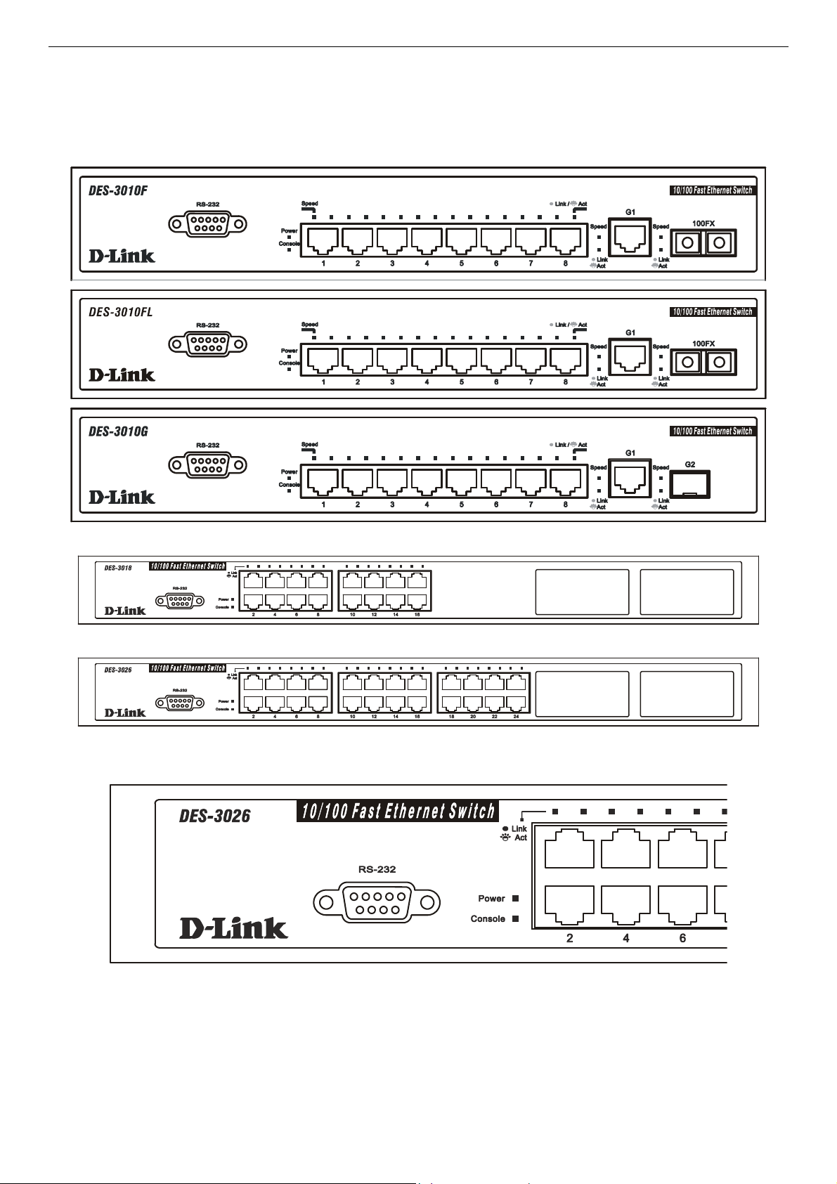
Front-Panel Components and LED Indicators
The front panel of the Switch consists of LED indicators for Power, Console, Link/Act and Speed, 8/16/24 Fast-Ethernet, ports,
two optional module ports (DES-3018/3026 only), a gigabit 1000BASE-T copper port (DES-3010F/G), a 100BASE-FX Ethernet
port (DES-3010F, DES-3010FL) and a SFP Gigabit Ethernet port (DES-3010G). Also, the front panel has a RS-232
communication port.
Figure 1- 1. DES-3010F/FL/G Front Panel
Figure 1- 2. DES-3018 Front Panel
Figure 1- 3. DES-3026 Front Panel
Figure 1- 4. DES-3026 LED indicators
4

DES-3010F/DES-3010FL/DES-3010G/DES-3018/DES-3026 Fast Ethernet Switch Manual
Comprehensive LED indicators display the status of the Switch and the network.
LED or Button Description
Power
This LED will light green after the Switch is powered on to indicate the normal operation
of the Switch’s power supplies. The indicator is dark when the Switch is powered off.
Console
This LED should blink during the Power-On Self Test (POST). When the POST is fin-
ished successfully, the LED goes dark. This indicator will light solid green when the
Switch is being logged into via out-of-band/local console management through the RS-
232 console port in the front of the Switch using a straight-through serial cable.
Link/Act
When the LED mode has been changed to Link/Act, the LEDs will light steady green to
indicate a valid link. A blinking LED indicates activity on the port.
Speed
To the right of every Link/Act LED lies the speed LED, corresponding to every port.
Depending on the switch model, these lights will assume different roles.
DES-3010F/FL/G – A solid green LED indicates the port is transferring data at
100Mbps while a dark, unlit LED will indicate a rate of 10Mbps.
Port 9 – The LED of this port, when lit solid green, indicates a transfer rate of
1000Mbps. When this LED is unlit, it denotes a transfer rate of 10/100Mbps.
Port 10 – For the 3010F and 3010FL, a solid green LED indicates a transfer
rate of 100Mbps and a dark LED indicates no link. For the 3010G, solid green LED
indicates a transfer rate of 1000Mbps and a dark LED indicates no link
DES-3018 / DES-3026 – A solid green LED will indicate a valid link at 100Mbps, and
when blinking, indicates the port is currently transferring data. A solid amber LED will
indicate a valid link at 10Mbps, and when blinking, indicates the port is currently
transferring data.
5
DES-3010F/DES-3010FL/DES-3010G/DES-3018/DES-3026 Fast Ethernet Switch Manual
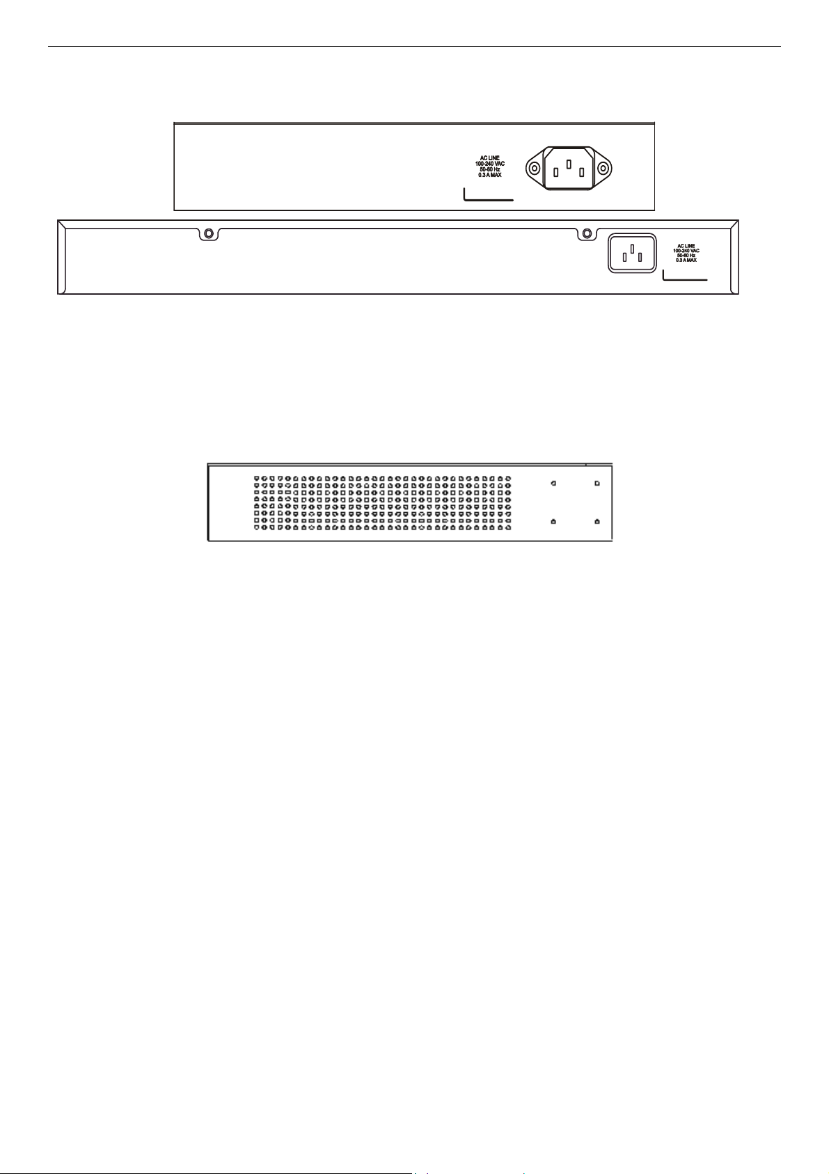
Rear Panel Description
The rear panels of these switches contain an AC power connector.
Figure 1- 5. Rear Panel of the DES-3010F/FL/G and DES-3018/DES-3026
Side Panel Description
Both panels of the Switch contain a heat vent used to dissipate heat. Do not block these openings, and leave at least 6 inches of
space at the rear and sides of the Switch for proper ventilation. Be reminded that without proper heat dissipation and air
circulation, system components might overheat, which could lead to system failure.
Figure 1- 6. Side panel view
6

DES-3010F/DES-3010FL/DES-3010G/DES-3018/DES-3026 Fast Ethernet Switch Manual
SECTION 2
Installation
Package Contents
Before You Connect to the Network
Installing the Switch without the Rack
Rack Installation
Power On
The Optional Module
Redundant Power System
Package Contents
Open the shipping carton of the Switch and carefully unpack its contents. The carton should contain the following items:
One DES-3010F, DES-3010FL, DES-3010G, DES-3018, or DES-3026 Fast Ethernet Switch •
•
•
•
•
•
•
•
•
•
•
•
•
•
Mounting kit (two brackets and screws)
Four rubber feet with adhesive backing
One AC power cord
RS-232 console cable
One CD Kit for User’s Guide / CLI / D-View module / SNMP module
This Manual with Registration Card.
If any item is missing or damaged, please contact your local D-Link Reseller for replacement.
Before You Connect to the Network
The site where you install the Switch may greatly affect its performance. Please follow these guidelines for setting up the Switch.
Install the Switch on a sturdy, level surface that can support the weight of the Switch. Do not place heavy objects on the
Switch.
The power outlet should be within 1.82 meters (6 feet) of the Switch.
Visually inspect the power cord and see that it is fully secured to the AC power port.
Make sure that there is proper heat dissipation from and adequate ventilation around the Switch. Leave at least 10 cm (4
inches) of space at the front and rear of the Switch for ventilation.
Install the Switch in a fairly cool and dry place for the acceptable temperature and humidity operating ranges.
Install the Switch in a site free from strong electromagnetic field generators (such as motors), vibration, dust, and direct
exposure to sunlight.
When installing the Switch on a level surface, attach the rubber feet to the bottom of the device. The rubber feet
cushion the Switch, protect the casing from scratches and prevent it from scratching other surfaces.
7
DES-3010F/DES-3010FL/DES-3010G/DES-3018/DES-3026 Fast Ethernet Switch Manual
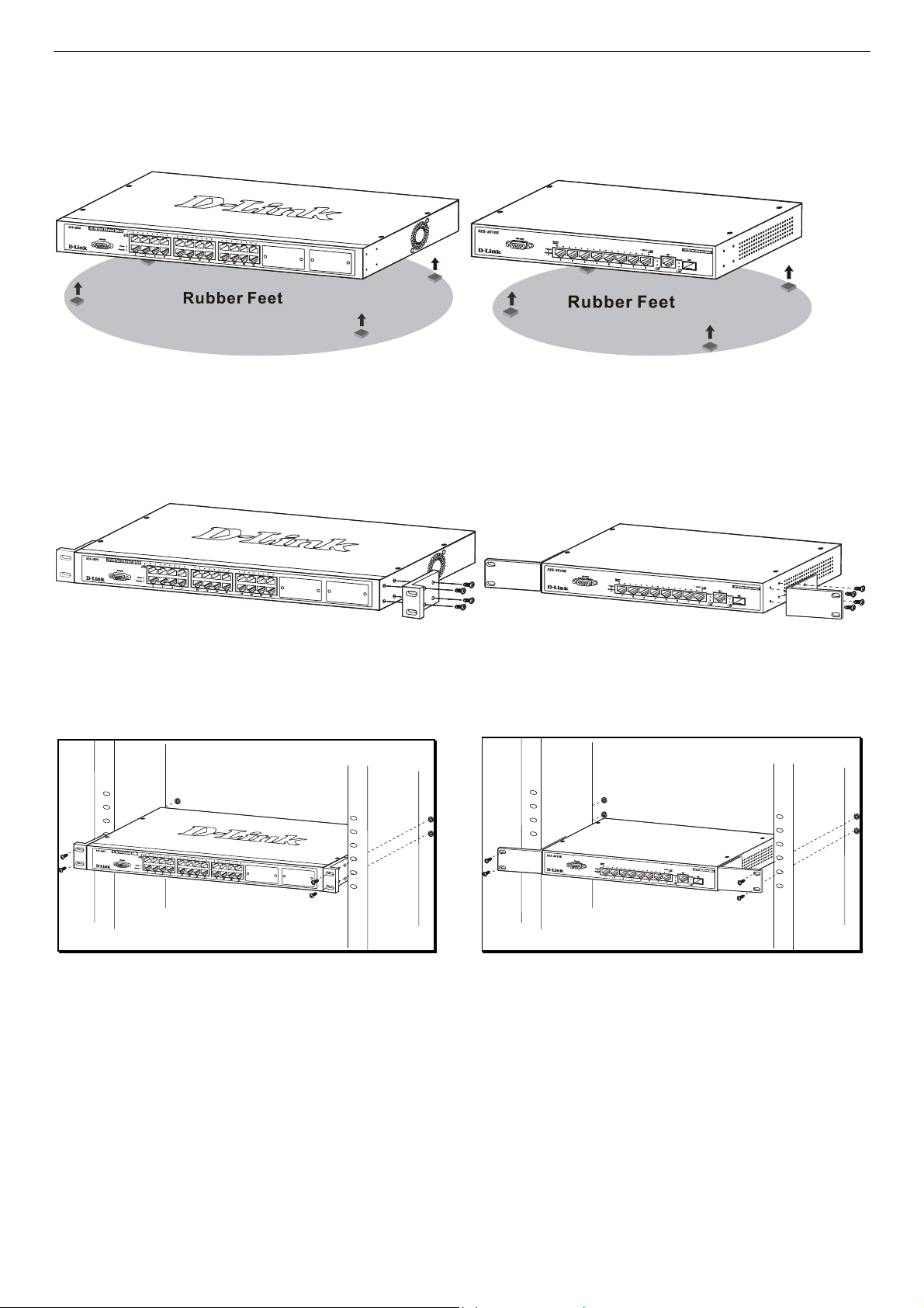
Installing the Switch without the Rack
When installing the Switch on a desktop or shelf, the rubber feet included with the Switch should first be attached. Attach these
cushioning feet on the bottom at each corner of the device. Allow enough ventilation space between the Switch and any other
objects in the vicinity.
Figure 2- 1. Prepare Switch for installation on a desktop or shelf
Installing the Switch in a Rack
The Switch can be mounted in a standard 19" rack. Use the following diagrams to guide you.
Figure 2- 2. Fasten mounting brackets to Switch
Fasten the mounting brackets to the Switch using the screws provided. With the brackets attached securely, you can mount the
Switch in a standard rack as shown in Figure 2-3 on the following page.
Mounting the Switch in a Standard 19" Rack
Figure 2- 3. Installing Switch in a rack
Power On
Plug one end of the AC power cord into the power connector of the Switch and the other end into the local power source outlet.
After the Switch is powered on, the LED indicators will momentarily blink. This blinking of the LED indicators represents a reset
of the system.
As a precaution, in the event of a power failure, unplug the Switch. When power is resumed, plug the Switch back in.
8
DES-3010F/DES-3010FL/DES-3010G/DES-3018/DES-3026 Fast Ethernet Switch Manual
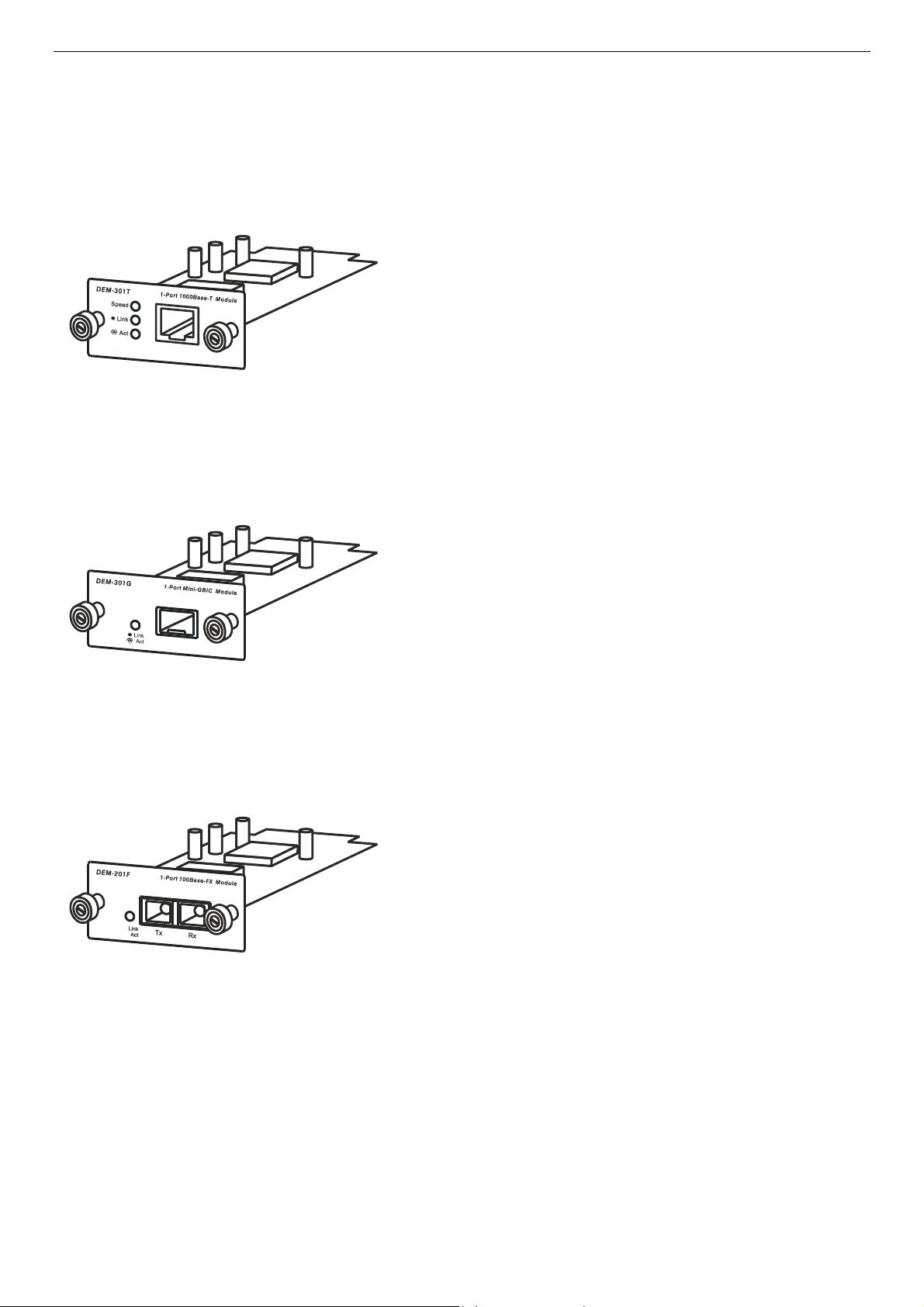
The Optional Modules
At the front right of the DES-3018 and the DES-3026 resides an optional module slot. These optional modules, specially designed
for this Switch series, may be used as an uplink to a server or core switch. This slot may be equipped with a single-port Uplink
Module, sold separately. See the explanation of the optional modules below.
- Single-Port 1000BASE-T Gigabit-Ethernet uplin
k
module
- Compliant with IEEE802.3, IEEE802.3u,
IEEE802.3ab
- Comprehensive LEDs for Speed, Link and Act(ivity)
- Supports auto-negotiation in 10/100/1000M, full-
duplex, back-pressure in half-duplex and
IEEE802.3x compliant flow control for full-duplex
- Single-Port SFP gigabit uplink module
- Compliant with IEEE802.3z
- Link and Act(ivity) LED
- Supports auto-negotiation in full-duplex and
IEEE802.3x compliant flow control for full-duplex
- Support for DEM-310GT, DEM-311GT, DEM-
314GT, DEM-315GT
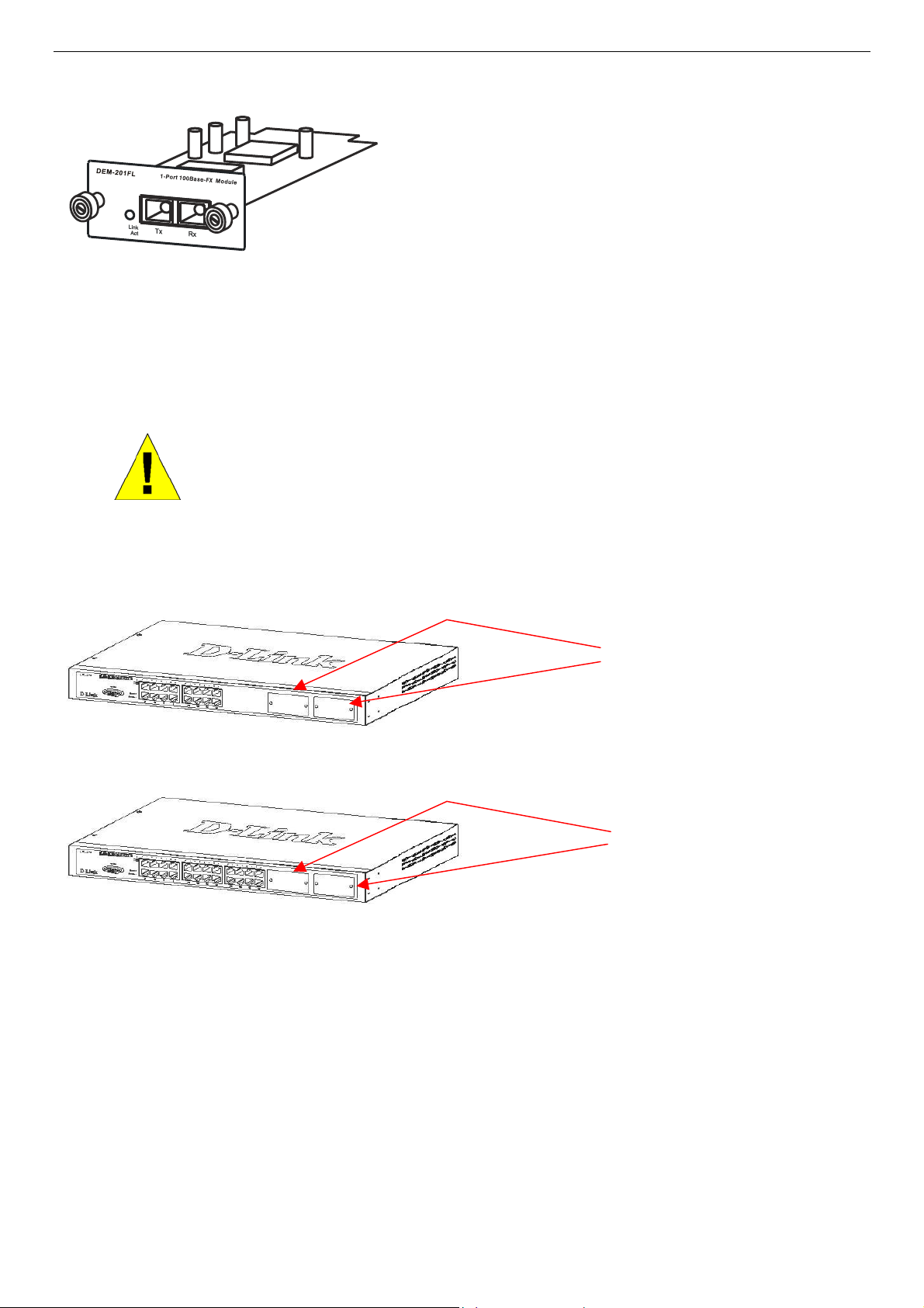
- Single-Port 100BASE-FX fast Ethernet uplink
module
- Compliant with IEEE802.3u
- Link and Act(ivity) LED
- Supports forced 100M, full-duplex and IEEE802.3x
compliant flow control for full-duplex
- SC Type connector good over 2km distance
Figure 2- 4. DEM-301T Optional Module
Figure 2- 5. DEM-301G Optional Module
Figure 2- 6. DEM-201F Optional Module
9
DES-3010F/DES-3010FL/DES-3010G/DES-3018/DES-3026 Fast Ethernet Switch Manual
- Single-Port 100BASE-FX fast Ethernet uplink
module
- Compliant with IEEE802.3u
- Link and Act(ivity) LED
- Supports forced 100M, full-duplex and IEEE802.3
x
compliant flow control for full-duplex
- SC Type connector good over 15km distance
Figure 2- 7. DEM-201FL Optional Module
To install the modules, follow the simple steps listed below.
CAUTION: Before adding the optional module, make sure to disconnect all power
sources connected to the Switch. Failure to do so may result in an electrical shock,
which may cause damage, not only to the individual but to the Switch as well.
At the front of the Switch to the right is the slot for the optional module, as shown in Figure 2-8 and Figure 2-9. This slot should
be covered with a faceplate that can be easily removed by loosening the screws and pulling off the plate.
Figure 2- 8. Optional Module slots at the front of the DES-3018
Optional Module Slots
Optional Module Slots
Figure 2- 9. Optional Module slot at the front of the DES-3026
Take the module and gently slide it in to the available slot at the front of the Switch until it reaches the back, as shown in the
following figure. At the back of the slot is a plug that must be connected to the module. Gently, but firmly push in on the module
to secure it to the Switch. The module should fit snugly into the corresponding receptor.
10

DES-3010F/DES-3010FL/DES-3010G/DES-3018/DES-3026 Fast Ethernet Switch Manual
Figure 2- 10. Inserting the optional module into the Switch.
The upgraded DES-3018 / DES-3026 is now ready for use.
11
DES-3010F/DES-3010FL/DES-3010G/DES-3018/DES-3026 Fast Ethernet Switch Manual
Section 3
Connecting the Switch
Switch To End Node
Switch to Hub or Switch
Connecting To Network Backbone or Server
NOTE: All high-performance N-Way Ethernet ports can support both MDI-
II and MDI-X connections.
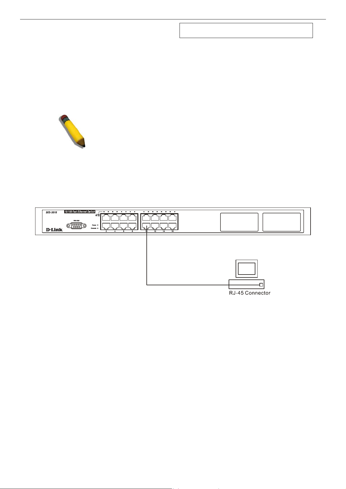
Switch to End Node
End nodes include PCs outfitted with a 10, 100 or 1000 Mbps RJ 45 Ethernet Network Interface Card (NIC) and most routers.
An end node can be connected to the Switch via a twisted-pair UTP/STP cable. The end node should be connected to any of the
10/100BASE-T ports of the Switch.
Figure 3- 1. Switch connected to an end node
The Link/Act LEDs for each UTP port will light green or amber when the link is valid. A blinking LED indicates packet activity
on that port.
12
DES-3010F/DES-3010FL/DES-3010G/DES-3018/DES-3026 Fast Ethernet Switch Manual
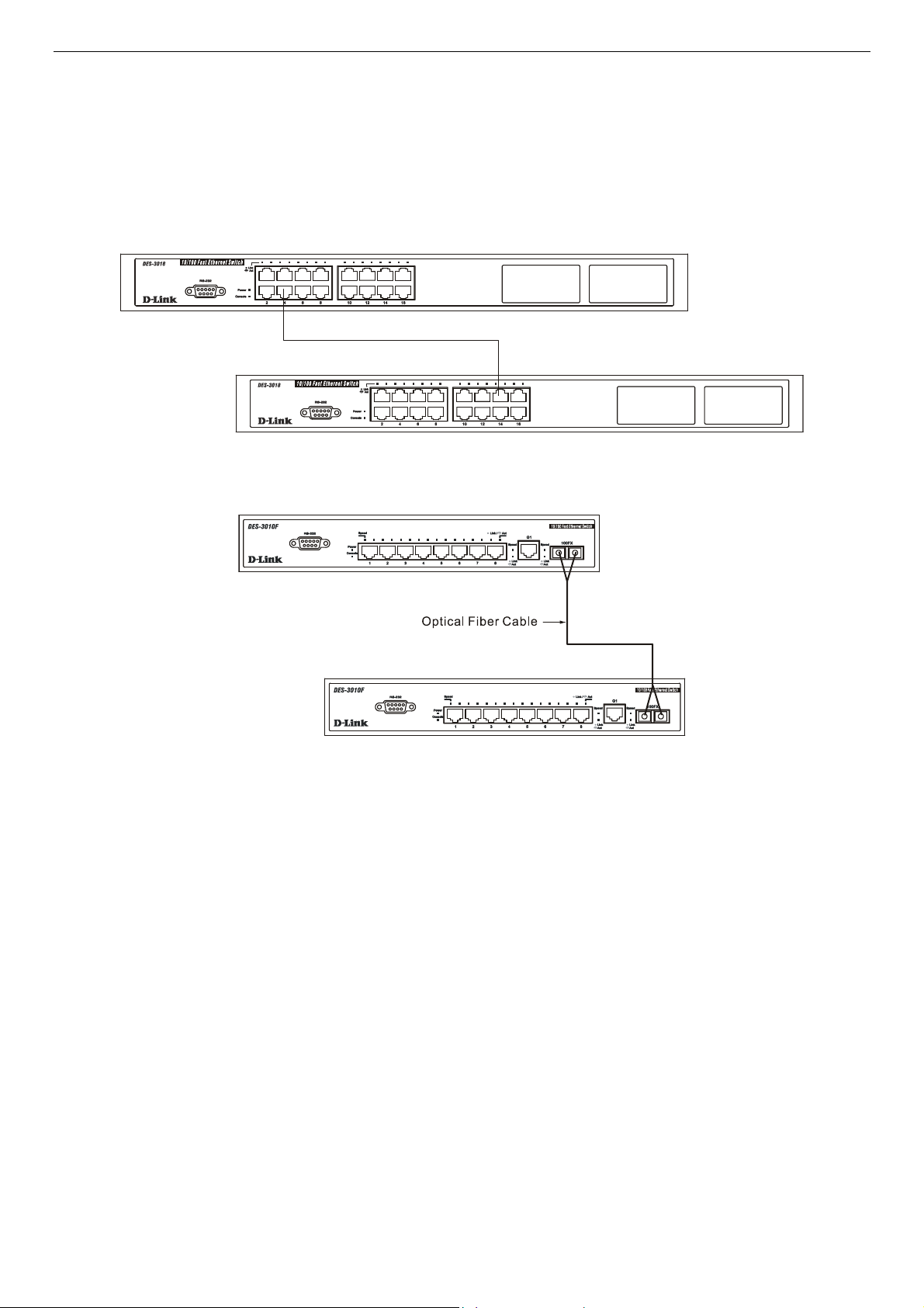
Switch to Hub or Switch
These connections can be accomplished in a number of ways using a normal cable.
A 10BASE-T hub or switch can be connected to the Switch via a twisted-pair Category 3, 4 or 5 UTP/STP cable. •
•
•
•
A 100BASE-TX hub or switch can be connected to the Switch via a twisted-pair Category 5 UTP/STP cable.
A 1000BASE-T switch can be connected to the Switch via a twisted pair Category 5e UTP/STP cable.
A switch supporting a fiber-optic uplink can be connected to the Switch’s SFP ports via fiber-optic cabling.
Figure 3- 2. Switch connected to a port on a hub or switch using a straight or crossover cable
Figure 3- 3. Switch connected to switch using fiber-optic cabling
13
DES-3010F/DES-3010FL/DES-3010G/DES-3018/DES-3026 Fast Ethernet Switch Manual
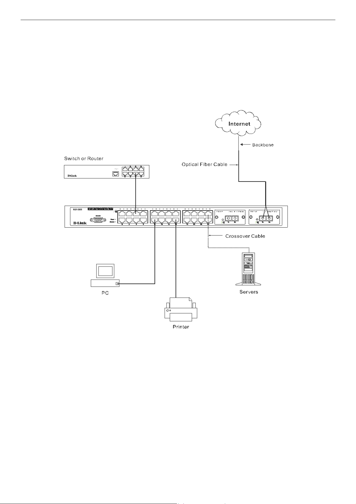
The DES-3010F/FL/G, DES-3018 or DES-3026 as a Network Backbone
The DES-3018 can be employed as a network backbone for offices or buildings that require many Ethernet connections within a
confined space. Once a high-speed line has been connected from the ISP, the DES-3018 can farm out connections for various end
nodes including PCs, printers, hubs, routers or other switches. The topology configurations are endless but be sure that
connections coming from the DES-3018 are at a equal or slower speed than the ISP uplink to avoid bottlenecking.
The copper ports operate at a speed of 100Mbps or 10Mbps in full or half duplex mode. The 100BASE-FX ports can operate at
100Mbps in full duplex mode only. Copper gigabit ports may operate in 1000Mbps in full-duplex only. SFP gigabit ports operate
in 1000Mbps in full-duplex only.
Connections to the Gigabit Ethernet ports are made using a fiber-optic cable or Category 5e copper cable, depending on the type
of port. A valid connection is indicated when the Link LED is lit.
Figure 3- 4. Uplink Connection to a server, PC or switch stack.
14

DES-3010F/DES-3010FL/DES-3010G/DES-3018/DES-3026 Fast Ethernet Switch Manual
Section 4
Introduction to Switch Management
Management Options
Web-based Management Interface
SNMP-Based Management
Managing User Accounts
Command Line Console Interface through the Serial Port
Connecting the Console Port (RS-232 DCE)
First Time Connecting to the Switch
Password Protection
SNMP Settings
IP Address Assignment
Connecting Devices to the Switch
Management Options
This system may be managed out-of-band through the console port on the front panel or in-band using Telnet. The user may also
choose the web-based management, accessible through a web browser.
Web-based Management Interface
After you have successfully installed the Switch, you can configure the Switch, monitor the LED panel, and display statistics
graphically using a web browser, such as Netscape Navigator (version 6.2 and higher) or Microsoft® Internet Explorer (version
5.0).
SNMP-Based Management
You can manage the Switch with an SNMP-compatible console program. The Switch supports SNMP version 1.0, version 2.0c
and version 3.0. The SNMP agent decodes the incoming SNMP messages and responds to requests with MIB objects stored in the
database. The SNMP agent updates the MIB objects to generate statistics and counters.
Command Line Console Interface through the Serial Port
You can also connect a computer or terminal to the serial console port to access the Switch. The command-line-driven interface
provides complete access to all Switch management features.
Connecting the Console Port (RS-232 DCE)
The Switch provides an RS-232 serial port that enables a connection to a computer or terminal for monitoring and configuring the
Switch. This port is a female DB-9 connector, implemented as a data terminal equipment (DTE) connection.
To use the console port, you need the following equipment:
A terminal or a computer with both a serial port and the ability to emulate a terminal. •
• A null modem or crossover RS-232 cable with a female DB-9 connector for the console port on the Switch.
To connect a terminal to the console port:
1. Connect the female connector of the RS-232 cable directly to the console port on the Switch, and tighten the captive
retaining screws.
2. Connect the other end of the cable to a terminal or to the serial connector of a computer running terminal emulation
software. Set the terminal emulation software as follows:
15

DES-3010F/DES-3010FL/DES-3010G/DES-3018/DES-3026 Fast Ethernet Switch Manual
3. Select the appropriate serial port (COM port 1 or COM port 2).
4. Set the data rate to 9600 baud.
5. Set the data format to 8 data bits, 1 stop bit, and no parity.
6. Set flow control to none.
7. Under Properties, select VT100 for Emulation mode.
8. Select Terminal keys for Function, Arrow, and Ctrl keys. Ensure that you select Terminal keys (not Windows keys).
NOTE: When you use HyperTerminal with the Microsoft® Windows® 2000
operating system, ensure that you have Windows 2000 Service Pack 2 or
later installed. Windows 2000 Service Pack 2 allows you to use arrow keys
in HyperTerminal's VT100 emulation. See www.microsoft.com for
information on Windows 2000 service packs.
9. After you have correctly set up the terminal, plug the power cable into the power receptacle on the back of the Switch.
The boot sequence appears in the terminal.
10. After the boot sequence completes, the console login screen displays.
11. If you have not logged into the command line interface (CLI) program, press the Enter key at the User Name and
password prompts. There is no default user name and password for the Switch. User names and passwords must first be
created by the administrator. If you have previously set up user accounts, log in and continue to configure the Switch.
12. Enter the commands to complete your desired tasks. Many commands require administrator-level access privileges. Read
the next section for more information on setting up user accounts. See the DES-3018 Command Line Interface
Reference Manual on the documentation CD for a list of all commands and additional information on using the CLI.
13. When you have completed your tasks, exit the session with the logout command or close the emulator program.
Make sure the terminal or PC you are using to make this connection is configured to match these settings.
If you are having problems making this connection on a PC, make sure the emulation is set to VT-100. You will be able to set the
emulation by clicking on the File menu in you HyperTerminal window, clicking on Properties in the drop-down menu, and then
clicking the Settings tab. This is where you will find the Emulation options. If you still do not see anything, try rebooting the
Switch by disconnecting its power supply.
Once connected to the console, the screen below will appear on your console screen. This is where the user will enter commands
to perform all the available management functions. The Switch will prompt the user to enter a user name and a password. Upon
the initial connection, there is no user name or password and therefore just press enter twice to access the command line interface.
Figure 4- 1. Initial screen after first connection.
16

DES-3010F/DES-3010FL/DES-3010G/DES-3018/DES-3026 Fast Ethernet Switch Manual
First Time Connecting to the Switch
The Switch supports user-based security that can allow you to prevent unauthorized users from accessing the Switch or changing
its settings. This section tells how to log onto the Switch.
NOTE: The passwords used to access the Switch are case-sensitive;
therefore, "S" is not the same as "s."
When you first connect to the Switch, you will be presented with the first login screen (shown below).
NOTE: Press Ctrl+R to refresh the screen. This command can be used at
any time to force the console program in the Switch to refresh the console
screen.
Figure 4- 2. Initial screen, first time connecting to the Switch
Press Enter in both the Username and Password fields. You will be given access to the command prompt DES-3018:4#, as shown
below:
There is no initial username or password. Leave the Username and Password fields blank.
17

DES-3010F/DES-3010FL/DES-3010G/DES-3018/DES-3026 Fast Ethernet Switch Manual
Figure 4- 3. Command Prompt
NOTE: The first user automatically gets Administrator level privileges. It is
recommended to create at least one Admin-level user account for the Switch.
18
 Loading...