


00_CV_3P211822-2C.fm Page 1 Tuesday, November 27, 2007 6:24 PM
INSTALLATION
MANUAL
R22 Split Series
Installation manual |
English |
|
R22 Split series |
||
|
||
Рóêоводство по монтажó |
|
|
|
||
Рóссêий |
||
Серия R22 с раздельной óстановêой |
||
|
|
Models
FTY25GXV1
FTY35GXV1
01_EN_3P211822-2C.fm Page 1 Tuesday, November 27, 2007 6:31 PM
Safety Precautions
•Read these Safety Precautions carefully to ensure correct installation.
•This manual classifies the precautions into WARNING and CAUTION.
Be sure to follow all the precautions below: they are all important for ensuring safety.
WARNING............... |
Failure to follow any of WARNING is likely to result in such grave consequences as death or serious injury. |
||
CAUTION .............. |
Failure to follow any of CAUTION may in some cases result in grave consequences. |
||
• The following safety symbols are used throughout this manual: |
|
||
|
|
|
|
Be sure to observe this instruction. |
Be sure to establish an earth connection. |
Never attempt. |
|
|
|
|
|
•After completing installation, test the unit to check for installation errors. Give the user adequate instructions concerning the use and cleaning of the unit according to the Operation Manual.
 WARNING
• Installation should be left to the dealer or another professional.
Improper installation may cause water leakage, electrical shock, or fire.
• Install the air conditioner according to the instructions given in this manual.
Incomplete installation may cause water leakage, electrical shock, or fire.
• Be sure to use the supplied or specified installation parts.
Use of other parts may cause the unit to come to lose, water leakage, electrical shock, or fire.
• Install the air conditioner on a solid base that can support the unit’s weight.
An inadequate base or incomplete installation may cause injury in the event the unit falls off the base.
• Electrical work should be carried out in accordance with the installation manual and the national electrical wiring rules or code of practice.
Insufficient capacity or incomplete electrical work may cause electrical shock or fire.
•Be sure to use a dedicated power circuit. Never use a power supply shared by another appliance.
•For wiring, use a cable long enough to cover the entire distance with no connection.
Do not use an extension cord. Do not put other loads on the power supply, use a dedicated power circuit.
(Failure to do so may cause abnormal heat, electric shock or fire.)
• Use the specified types of wires for electrical connections between the indoor and outdoor units.
Firmly clamp the interconnecting wires so their terminals receive no external stresses. Incomplete connections or clamping may cause terminal overheating or fire.
• After connecting interconnecting and supply wiring be sure to shape the cables so that they do not put undue force on the electrical covers or panels.
Install covers over the wires. Incomplete cover installation may cause terminal overheating, electrical shock, or fire.
• If any refrigerant has leaked out during the installation work, ventilate the room.
(The refrigerant produces a toxic gas if exposed to flames.)
• After all installation is complete, check to make sure that no refrigerant is leaking out.
(The refrigerant produces a toxic gas if exposed to flames.)
• When installing or relocating the system, be sure to keep the refrigerant circuit free from substances other than the specified refrigerant (R22), such as air.
(Any presence of air or other foreign substance in the refrigerant circuit causes an abnormal pressure rise or rupture, resulting in injury.)
• During pump-down, stop the compressor before removing the refrigerant piping.
If the compressor is still running and the stop valve is open during pump-down, air will be sucked in when the refrigerant piping is removed, causing abnormal pressure in the freezer cycle which will lead to breakage and even injury.
• During installation, attach the refrigerant piping securely before running the compressor.
If the compressor is not attached and the stop valve is open during pump-down, air will be sucked in when the compressor is run, causing abnormal pressure in the freezer cycle which will lead to breakage and even injury.
• Be sure to establish an earth. Do not earth the unit to a utility pipe, arrester, or telephone earth.
Incomplete earth may cause electrical shock, or fire. A high surge current from lightning or other sources may cause damage to the air conditioner.
• Be sure to install an earth leakage breaker. Failure to install an earth leakage breaker may result in electric shocks, or fire.
 CAUTION
• Do not install the air conditioner in a place where there is danger of exposure to inflammable gas leakage.
If the gas leaks and builds up around the unit, it may catch fire.
•Establish drain piping according to the instructions of this manual. Inadequate piping may cause flooding.
•Tighten the flare nut according to the specified method such as with a torque wrench.
If the flare nut is tightened too hard, the flare nut may crack after a long time and cause refrigerant leakage.
• Make sure to provide for adequate measures in order to prevent that the outdoor unit be used as a shelter by small animals.
Small animals making contact with electrical parts can cause malfunctions, smoke or fire. Please instruct the customer to keep the area around the unit clean.
■English |
1 |
|
|||
|
|
|
|
|
|
|
|
|
|
|
|
|
|
|
|
|
|
01_EN_3P211822-2C.fm Page 2 Tuesday, November 27, 2007 6:31 PM
Accessories
|
A – J , Outdoor unit |
|
K |
|
|
|
|
|||
|
|
|
|
|
|
|
|
|||
A |
Mounting plate |
1 |
|
D Remote controller holder |
1 |
G Thermistor cable (8m)*1 |
1 |
|||
|
|
|
|
|
|
|
|
|
|
|
B |
Air-Purifying Filter with |
|
|
E |
AAA dry-cell batteries |
2 |
H |
Operation manual |
1 |
|
2 |
|
|
|
|
|
|
|
|||
|
bacteriostatic, virustatic function |
|
|
|
|
J |
Installation manual |
1 |
||
|
|
|
|
|
|
|||||
|
|
|
|
|
F |
Indoor unit fixing screw |
|
|||
|
|
|
|
|
2 |
|
|
|
||
C |
Wireless remote controller |
1 |
|
|
M4 × 12L |
K |
Drain plug |
1 |
||
|
|
|
||||||||
|
|
|
|
|||||||
|
|
|
|
|
|
|
|
|
|
|
*1 The thermistor cable is attached to the indoor unit.
Choosing a Site
• Before choosing the installation site, obtain user approval.
The indoor unit should be sited in a place where:
•the restrictions on installation specified in the indoor unit installation drawings are met,
•both air intake and exhaust have clear paths met,
•the unit is not in the path of direct sunlight,
•the unit is away from the source of heat or steam,
•there is no source of machine oil vapour (this may shorten indoor unit life),
•cool (heat) air is circulated throughout the room,
•the unit is away from electronic ignition type fluorescent lamps (inverter or rapid start type) as they may shorten the remote control range,
•the unit is at least 1 metre away from any television or radio set (unit may cause interference with the picture or sound).
Outdoor unit
The outdoor unit should be sited in a place where:
•the restrictions on installation specified in the outdoor unit installation diagram are met,
•drain water causes no trouble or problem in particular,
•both air intake and exhaust have clear paths of air (they should be free of snow in snowy districts),
•the unit is in a clear path of air but not directly exposed to rain, strong winds, or direct sunlight,
•there is no fear of inflammable gas leakage,
•the unit is no directly exposed to salt, sulfidized gases, or machine oil vapour (they may shorten outdoor unit life),
•operation noise or hot air flow does not cause trouble to neighbours,
•the unit is at least 3 metres away from any television or radio antenna.
•Turn on all the fluorescent lamps in the room, if any, and find the site where remote controller signals are properly received by the indoor unit (within 7 metres).
Installation Tips
1. Removing and installing front panel.
• Removal method
1)Place your fingers in the indentations on the main unit (one each on the left and right sides), and open the panel until it stops.
2)Continue to open the front panel further while sliding the panel to the right and pulling it toward you in order to disengage the rotating shaft on the left side. To disengage the rotating shaft on the right side, slide the panel to the left while pulling it toward you.
•Installation method
Align the tabs of the front panel with the grooves, and push all the way in. Then close slowly. Push the center of the lower surface of the panel firmly to engage the tabs.
Rotating shaft
Push the rotating shaft of the front panel into the groove.
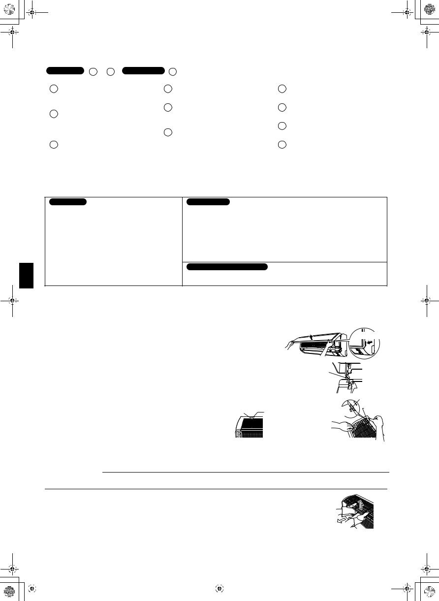
2. Removing and installing front grille.
• Removal method |
Upper hook |
|
|
|
|
1) |
Remove front panel to remove the air filter. |
|
2) |
Remove the screws (2) from the front grille. |
|
3) |
In front of the {{{ mark of the front grille, there are 3 |
|
|
upper hooks. Lightly pull the front grille toward you with one |
|
|
hand, and push down on the hooks with the fingers of your other hand. |
|
|
Lightly pull the |
mark area |
front grille |
toward you with |
|
(3 locations) |
one hand, and |
|
push down on |
|
the hooks with |
|
the fingers of |
|
your other hand. |
|
(3 locations) |
Indentations on the main unit
|
Upper hook |
Push |
Upper hook |
down. |
|
When there is no work space because the unit is close to ceiling  CAUTION
Be sure to wear protection gloves.
Place both hands under the center of the front grille, and while pushing up, pull it toward you.
• Installation method
1) Push up.
1)Install the front grille and firmly engage the upper hooks (3 locations).
2)Install 2screws of the front grille.
3)Install the air filter and then mount the front panel.
2) Pull toward you.
2 |
|
|
■English |
||
|
|
|
|
|
|
|
|
|
|
|
|
|
|
|
|
|
|

01_EN_3P211822-2C.fm Page 3 Tuesday, November 27, 2007 6:31 PM
Indoor/Outdoor Unit
Installation Drawings
A Mounting plate
Mounting plate fixing screw
(Field supply: M4 × 25L)
How to attach the indoor unit.
Hook the claws of the bottom frame to the mounting plate.
If the claws are difficult to hook, remove the front grille.
How to remove the indoor unit.
Push up the marked area (at the lower part of the front grille) to
release the claws. If it is difficult to Front grille release, remove the front grille.
 A Mounting
plate
Clip
Bottom frame Mark (rear side)
30mm or more from ceiling
Front panel
50mm or more from walls (on both sides)
M4 × 12L
Air filter
BAir-Purifying Filter with bacteriostatic, virustatic function (2)
Air-Purifying Filter |
Air filter |
|
|
with bacteriostatic, |
|
virustatic function |
|
Filter frame |
|
Tab |
|
Service lid
 Opening service lid
Service lid is opening/closing type.
 Opening method
1)Remove the service lid screws.
2)Pull out the service lid diagonally down in the direction of the arrow.
3)Pull down.
|
Cut thermal insulation |
|
Caulk |
pipe to an appropriate |
|
length and wrap it with |
||
pipe hole |
||
tape, making sure that no |
||
gap |
||
gap is left in the insulation |
||
with putty. |
||
pipe’s cut line. |
||
|
||
|
Wrap the insulation pipe with |
|
|
the finishing tape from bottom |
|
|
to top. |
|
|
|
|
|
Model |
25 |
35 |
|
|
Min. allowable length |
3m |
|
|
|
|
||||
|
|
|
|
|
Max. allowable length |
15m |
|
|
|
Additional charge of refrigerant |
20g/m |
|
|
|
|
|
|
|
|
Max. allowable length without |
10m |
|
|
|
additional charge |
|
|
||
|
|
|
|
|
|
|
|
|
|
Max. allowable height |
10m |
|
|
|
|
|
|
|
|
Gas pipe |
O.D. 9.5mm |
O.D. 12.7mm |
|
|
|
|
|
|
|
Liquid pipe |
O.D. 6.4mm |
|
|
|
|
|
|
|
|
*Be sure to add the proper amount of additional refrigerant. Failure to do so may result in reduced perfomance.
Stop valve cover
C Wireless remote controller
D Remote controller holder
Screws  (Field supply: M3 × 20L)
Before screwing the remote controller holder to the wall, make sure that control signals are properly received by indoor unit.
250mm |
from wall |
|
311 |
bolt |
- |
hole |
|
|
||
Footcentres |
|||
 How to remove the stop valve cover.
 Remove the screw on the stop valve cover.
 Slide the lid downward to remove it.
 How to attach the stop valve cover.
 Insert the upper part of
the stop valve cover into the outdoor unit to install.  Tighten the screws.
(Foot |
574 |
|
|
|
|
|
|
|
bolt- |
|
|
|
|
Allow space for piping |
|
|
hole |
centres) |
105.5 |
|
|
||
|
|
|
|
and electrical servicing. |
|||
|
|
|
|
|
|||
|
|
(From |
|
|
|||
|
|
|
|
|
|
||
|
|
|
|
|
|
||
|
|
|
unit’s |
||||
|
|
|
|
side) |
|
|
|
In sites with poor drainage, use block |
|
Where there is a danger of the unit |
|
||||
|
|
|
|||||
bases for outdoor unit. Adjust foot height |
|
|
falling, use foot bolts, or wires. |
|
|||
until the unit is leveled. Otherwise, water |
|
|
|
|
|
||
|
unit: mm |
||||||
leakage or pooling of water may occur. |
|
||||||
|
|
|
|
|
|
|
|
■English |
3 |
|
|||
|
|
|
|
|
|
|
|
|
|
|
|
|
|
|
|
|
|

01_EN_3P211822-2C.fm Page 4 Tuesday, November 27, 2007 6:31 PM
Outdoor Unit Installation Guidelines
• Where a wall or other obstacle is in the path of outdoor unit’s intake or exhaust airflow, follow the installation guidelines below.
Wall facing one side |
Walls facing two sides |
|
More than 50 |
More than 100 |
|
|
More than 100 |
|
|
More |
|
|
than 150 |
|
|
More than 50 |
More than 50 |
|
Top view |
|
Side view |
|
|
Walls facing three sides
More than 150 |
|
More than 300 |
|
More |
|
than 50 |
|
Top view |
Unit: mm |
 CAUTION
When operating the air conditioner in a low outdoor ambient temperature, be sure to follow the instructions described below.
1)To prevent exposure to wind, install the outdoor unit with its suction side facing the wall.
2)Never install the outdoor unit at a site where the suction side may be exposed directly to wind.
3)To prevent exposure to wind, it is recommended to install a baffle plate on the air discharge side of the outdoor unit.
4)In heavy snowfall areas, select an installation site where the snow will not affect the unit.
 Construct a large canopy.
  Construct a pedestal.
Install the unit high enough off the ground to prevent burying in snow.
 CAUTION
In the case of using a mount and installing the outdoor unit on the wall or roof, attach vibration absorbers (e.g., vibration isolation rubbers and springs) between the legs of the outdoor unit and the mount (4 portions).
4 |
■English |
 Loading...