


INSTALLATION
MANUAL
|
|
Installation Manual |
|
|
|
|
|
Chilled Water Fan Coil Units |
|
|
Installationshandbuch |
|
|
Kaltwasser-Ventilator Luftkühler |
|
|
Manuel d’installation |
|
|
Ventilo-convecteur à eau glacée |
|
|
Installatiehandboek |
|
|
Koud Water-Ventilator Luchtkoeler |
|
|
Manual de instalación |
|
Unidades de serpentín de ventilador de agua fría |
|
|
|
Manuale Di Installazione |
|
|
Unità fan coil ad acqua fredda |
MODELS |
|
Εγχειρίδιο εγκατάστασης |
FWT02CATNMV1 |
|
|
Μονάδες πηνίου του ανεμιστήρα για το παγωμένó νερο |
||
FWT03CATNMV1 |
|
Manual De Instalação |
FWT04CATNMV1 |
|
|
Unidades de bobina de ventilador de água refrigerante |
||
FWT05CATNMV1 |
|
Руководство По Установке |
FWT06CATNMV1 |
|
|
ВентилЯторные доводчики с водЯным охлаждением |
||
|
|
Kurulum Kılavuzu |
|
|
So¤uk su fan bobin üniteleri |
English
Deutsch
Français
Nederlands
Español
Italiano
Ελληνικά
Português
Русский
Türkçe
IM-WMJW-0312(0)-DAIKIN (DENV)
Part No.: R08019037507

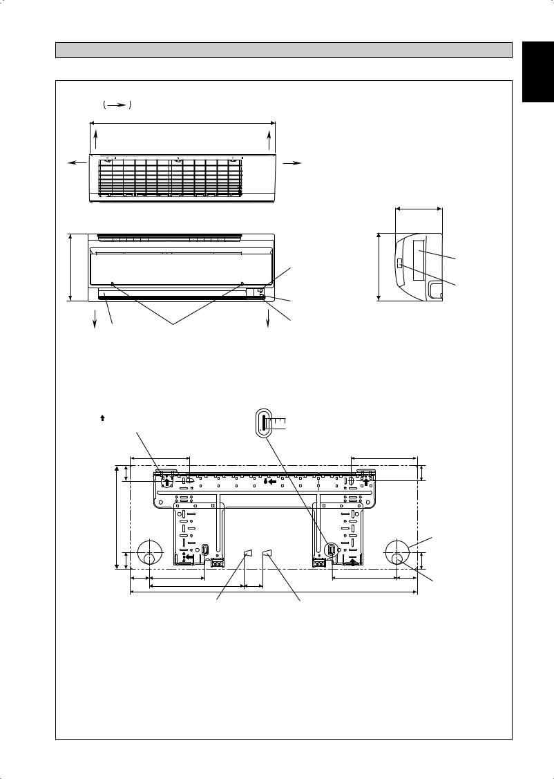
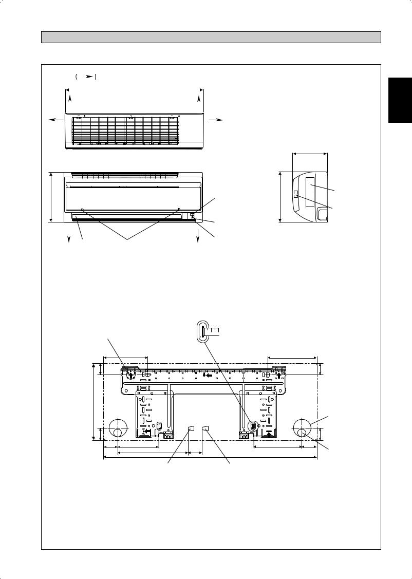
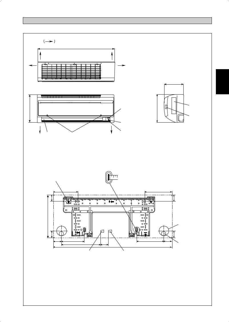
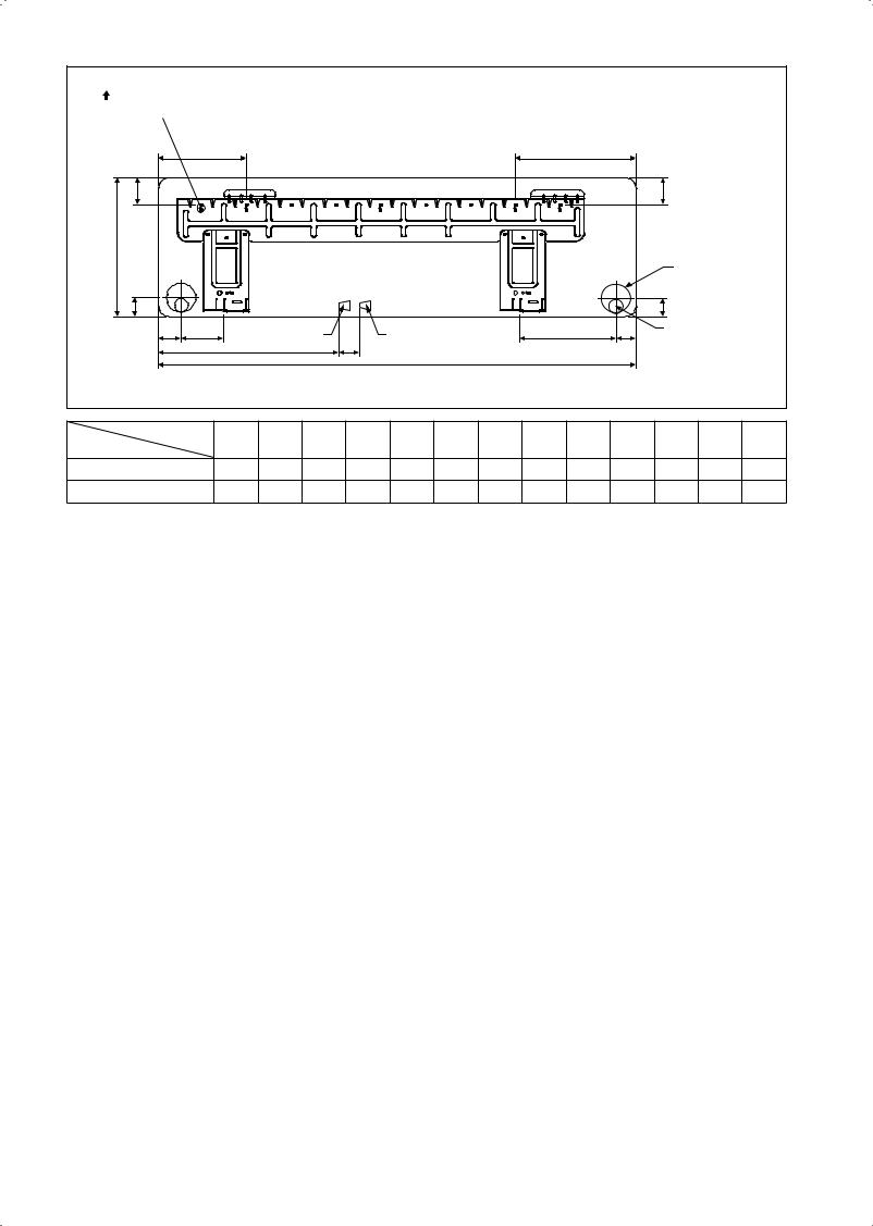
OUTLINE AND DIMENSIONS
Indoor Unit
THE MARK |
SHOWS PIPING DIRECTION |
|
A |
REAR |
REAR |
LEFT |
RIGHT |
C
TOP VIEW
|
|
SIGNAL RECEIVER |
|
NAME PLATE |
B |
|
B |
|
|
|
|
|
|
TERMINAL |
|
|
|
|
BLOCK |
|
|
INDOOR UNIT |
|
WITH EARTH |
|
|
SIDE VIEW |
TERMINAL |
|
BOTTOM |
BOTTOM |
ON/OFF SWITCH |
||
|
|
|
||
|
|
ROOM TEMPERATURE |
|
|
LOUVER |
FRONT GRILLE FIXED SCREWS |
THERMISTOR (INSIDE) |
|
|
|
(INSIDE) |
|
|
|
FRONT VIEW
Recommended mounting plate retention spots (5 spots in all)
D
F
B
Use tape measure as shown.  Position the end of a tape
measure at
E
F
Through the wall hole Ø 65mm
G |
|
|
|
G |
|
|
|
|
|
H |
J |
|
K |
I |
|
L |
M |
A |
Drain hose position |
|
|
|
|
|
|
Water inlet |
|
Water outlet |
|
|
INSTALLATION PLATE FWT02/03/04 |
|
||
All dimensions are in mm
Original Instruction English
1-1
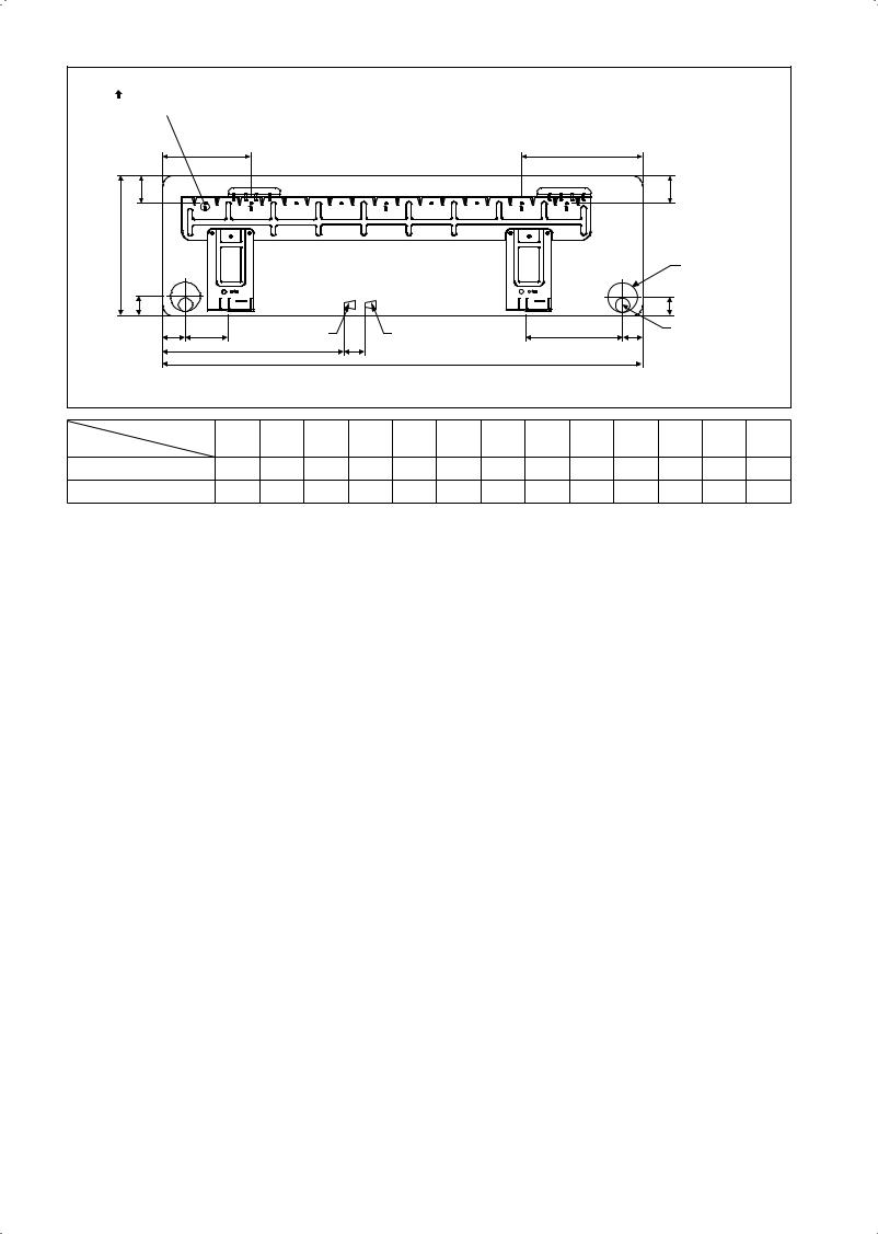
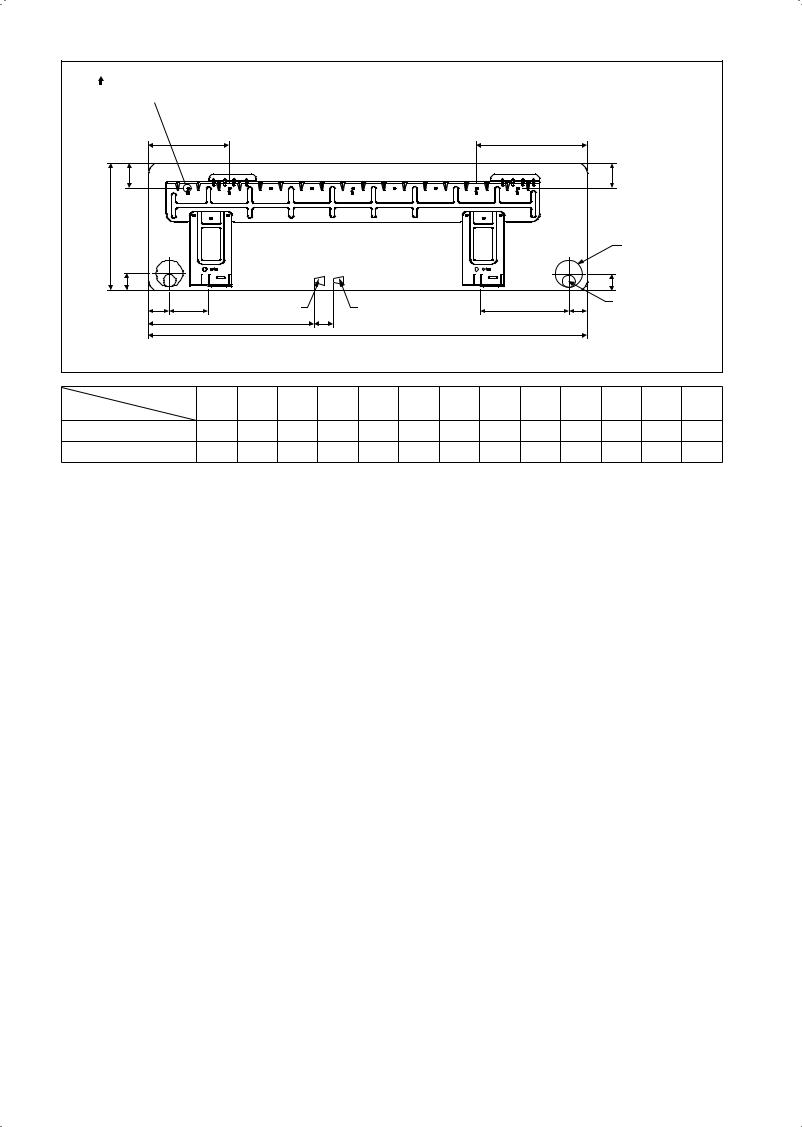
Recommended mounting plate retention |
|
|
|
|
|
|
|
|
|
|
||||
spots (7 spots in all) |
|
|
|
|
|
|
|
|
|
|
|
|
||
|
D |
|
|
|
|
|
|
|
|
E |
|
|
|
|
F |
|
|
|
|
|
|
|
|
|
|
|
F |
|
|
B |
|
|
|
|
|
|
|
|
|
|
|
|
|
|
|
|
|
|
|
|
|
|
|
|
|
|
Through the wall |
||
|
|
|
|
|
|
|
|
|
|
|
|
hole Ø 65mm |
|
|
G |
|
|
|
|
|
|
|
|
|
|
|
G |
|
|
H |
J |
|
Water inlet |
M |
Water outlet |
|
|
|
K |
I |
Drain hose position |
|||
|
|
L |
|
|
A |
|
|
|
|
|
|
|
|
|
|
|
|
|
|
|
|
|
|
|
|
|
|
|
|
|
|
|
|
INSTALLATION PLATE FWT05/06 |
|
|
|
All dimensions are in mm |
||||||
Dimension |
A |
B |
C |
D |
E |
F |
G |
H |
I |
J |
K |
L |
M |
|
Model |
|
|||||||||||||
|
|
|
|
|
|
|
|
|
|
|
|
|
|
|
FWT02/03/04 |
|
800 |
288 |
206 |
166 |
184 |
42 |
46 |
55 |
56 |
154 |
182 |
267 |
55 |
FWT05/06 |
|
1065 |
310 |
224 |
190 |
173 |
61 |
40 |
45 |
48 |
91 |
219 |
593 |
60 |
1-2
INSTALLATION MANUAL
This manual provides the procedures of installation to ensure a safe and good standard of operation for the air conditioner unit. Special adjustment may be necessary to suit local requirements.
Before using your air conditioner, please read this instruction manual carefully and keep it for future reference. This appliance is intended to be used by expert or trained users in shops, in light industry and on farms, or for commercial use by lay persons. This appliance is not intended for use by persons, including children, with reduced physical, sensory or mental capabilities, or lack of experience and knowledge, unless they have been given supervision or instruction concerning use of the appliance by a person responsible for their safety.
Children should be supervised to ensure that they do not play with the appliance.
SAFETY PRECAUTIONS
!WARNING
•Installation and maintenance should be performed by qualified persons who are familiar with local code and regulation, and experienced with this type of appliance.
•All field wiring must be installed in accordance with the national wiring regulation.
•Ensure that the rated voltage of the unit corresponds to that of the name plate before commencing wiring work according to the wiring diagram.
•The unit must be GROUNDED to prevent possible hazard due to insulation failure.
•All electrical wiring must not touch the refrigerant piping, or any moving parts of the fan motors.
•Confirm that the unit has been switched OFF before installing or servicing the unit.
•Disconnect from the main power supply before servicing the air conditioner unit.
•DO NOT pull out the power cord when the power is ON. This may cause serious electrical shocks which may result in fire hazards.
•Keep the indoor and outdoor units, power cable and transmission wiring, at least 1m from TVs and radios, to prevent distorted pictures and static. {Depending on the type and source of the electrical waves, static may be heard even when more than 1m away}.
! CAUTION
Please take note of the following important points when installing.
• Ensure that the drainage piping is connected properly.
If the drainage piping is not connected properly, it may cause water leakage which will dampen the furniture.
•Ensure that the unit’s panel is closed after service or installation.
Unsecured panels will cause the unit to operate noisily.
•Sharp edges and coil surfaces are potential locations which may cause injury hazards.
Avoid from being in contact with these places.
•Before turning off the power supply, set the remote controller’s ON/OFF switch to the “OFF” position to prevent the nuisance tripping of the unit. If this is not done, the unit’s fans will start turning automatically when power resumes, posing a hazard to service personnel or the user.
•Do not install the units at or near doorway.
•Do not operate any heating apparatus too close to the air conditioner unit or use in room where mineral oil, oil vapour or oil steam exist, this may cause plastic part to melt or deform as a result of excessive heat or chemical reaction.
•When the unit is used in kitchen, keep flour away from going into suction of the unit.
•This unit is not suitable for factory used where cutting oil mist or iron powder exist or voltage fluctuates greatly.
•Do not install the units at area like hot spring or oil refinery plant where sulphide gas exists.
•Ensure the color of wires of the outdoor unit and the terminal markings are same to the indoors respectively.
•IMPORTANT : DO NOT INSTALL OR USE THE AIR CONDITIONER UNIT IN A LAUNDRY ROOM.
•Don't use joined and twisted wires for incoming power supply.
•The equipment is not intended for use in a potentially explosive atmosphere.
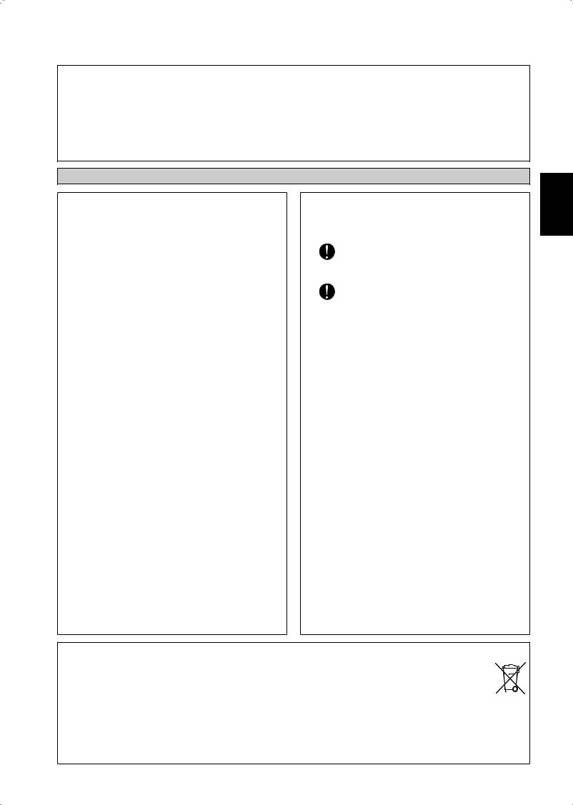
NOTICE
Disposal requirement
Your air conditioning product is marked with this symbol. This means that electrical and electronic products shall not be mixed with unsorted household waste.
Do not try to dismantle the system yourself: the dismantling of the air conditioning system, treatment of the refrigerant, of oil and of other parts must be done by a qualified installer in accordance with relevant local and national legislation.
Air conditioners must be treated at a specialized treatment facility for re-use, recycling and recovery. By ensuring this product is disposed of correctly, you will help to prevent potential negative consequences for the environment and human health. Please contact the installer or local authority for more information.
Batteries must be removed from the remote controller and disposed of separately in accordance with relevant local and national legislation.
English
1-3
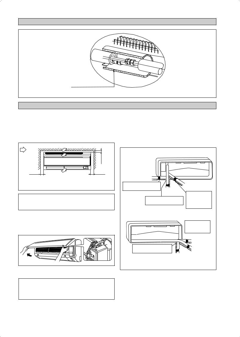
INSTALLATION DIAGRAM
CORK TAPE FULLY INSULATED
INSULATION THROUGH OUT CHILLED WATER PIPING
INSTALLATION OF THE INDOOR UNIT
The indoor unit must be installed in such a way so as to prevent short circuit of the cool discharged air with the hot return air. Please follow the installation clearance shown in the figure. Do not place the indoor unit where there could be direct sunlight shining on it. Also, this location must be suitable for piping and drainage, and be away from doors or windows.
Air flow |
|
min. 30 (Space for performance) |
|
(Indoor) |
|
||
|
|
||
min. 50 |
Required space |
min. 50 |
|
(Space for |
(Space for |
||
|
|||
maintenance) |
|
maintenance) |
|
|
All dimensions are in mm |
||
! CAUTION
Do not install the unit at altitude over 2000m.
Air Purging
To prevent pump damage, the fan coil unit should not be energized until the coil and all water lines have been purged of air.
The Air Vent located inside the casing. Removed the casing and connect hose to the air vent while doing purging.
The water piping can be routed to the unit in a number of ways (left or right from the back of the unit), by using the cut-out holes on the casing of the unit (see figure). Bend the pipes carefully to the required position in order to align it with the holes. For the side and bottom, hold the bottom of the piping and then position it to the required direction (see figure). The condensation drain hose can be taped to the pipes.
Right-side, right-back or right-bottom piping
Right-side piping
Remove pipe port cover here
for right-side piping
Right-bottom piping
Remove pipe port cover here for right-bottom piping
Right-back piping
Bind coolant pipe and drain hose together with insulating tape.
Left-side, left-back or left-bottom piping
Remove pipe port cover here for left-side piping
|
Left-side piping |
|
Remove pipe port cover here |
Left-back piping |
|
for left-bottom piping |
||
|
||
Left-bottom piping |
|
! CAUTION
Ensure there is no water droplets go into the control box during purging process.
1-4

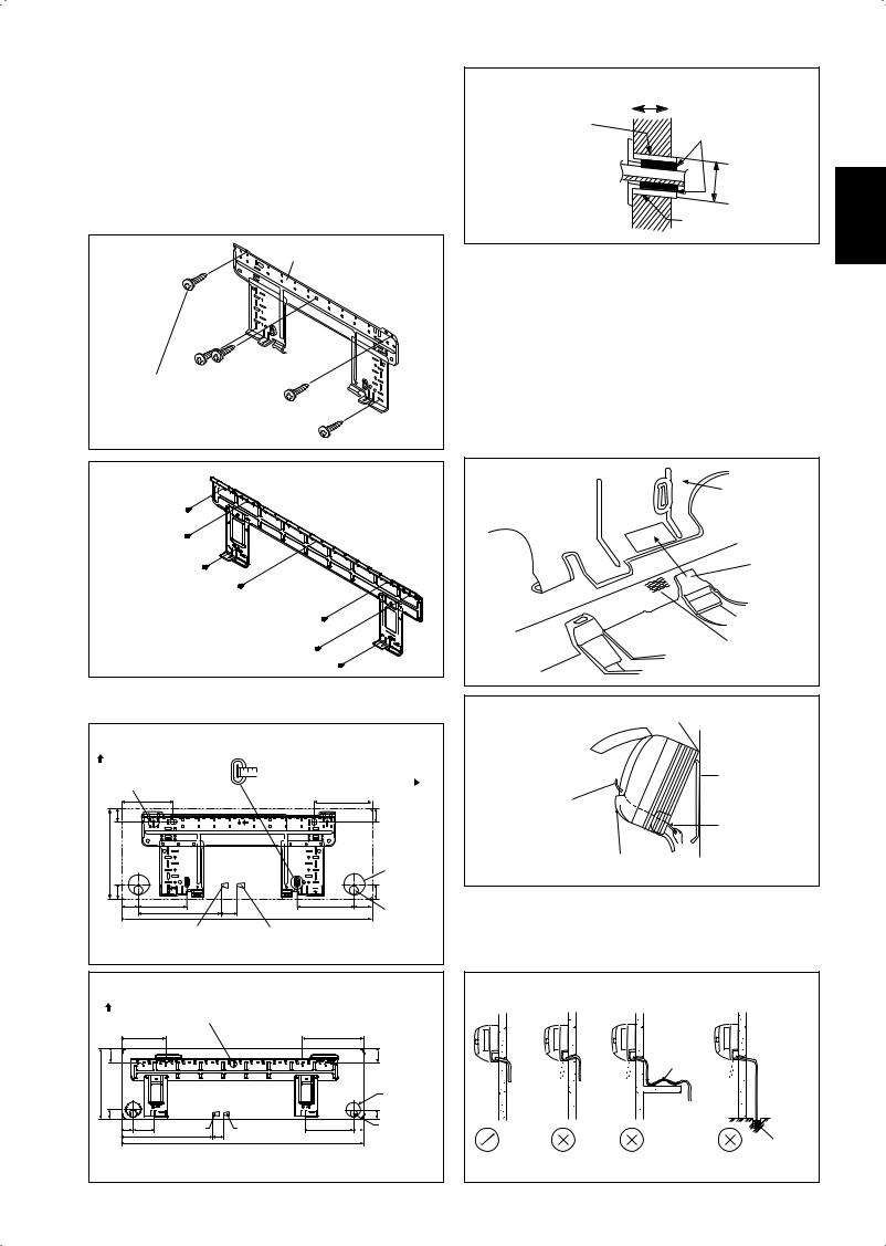
Mounting Installation Plate
Ensure that the wall is strong enough to withstand the weight of the unit. Otherwise, it is necessary to reinforce the wall with plates, beams or pillars.
Use the level gauge for horizontal mounting, and fix it with 5 suitable screws for FWT02/03/04 and 7 suitable screws for FWT05/06.
In case the rear piping draws out, drill a hole 65mm in diameter with a cone drill, slightly lower on the outside wall (see figure).
FWT02/03/04
Mounting plate
Mounting plate fixing screw
Hole with cone drill
Inside |
Outside |
Wall embedded pipe |
Caulking |
(Field supply) |
Ø 65
Wall hole cover
(Field supply) Wall embedded pipe (Field supply)
Mount The Unit Onto The Installation Plate
Hook the indoor unit onto the upper portion of the installation plate (Engage the two hooks at the rear top of the indoor unit with the upper edge of the installation plate). Ensure that the hooks are properly seated on the installation plate by moving it to the left and right.
How To Attach The Indoor Unit
Hook the claws of the bottom frame to the mounting plate.
How To Remove The Indoor Unit
Push up the marked area (at the lower part of the front grille) to release the claws.
FWT05/06
Mounting plate
Mounting plate  fixing screw
Recommended Mounting Plate Retention Spots And
Dimensions
FWT02/03/04
Recommended mounting |
Use tape measure as shown. |
||
plate retention spots |
Position the end of a tape |
||
(5 spots in all) |
measure at |
|
|
|
|
|
|
|
166 |
|
184 |
42.2 |
|
|
42.2 |
288 |
|
|
Through the |
|
|
|
wall hole |
|
|
|
Ø 65mm |
45.9 |
|
181.7 |
45.9 |
54.5 |
153.8 |
55.5 |
|
|
263 |
51.9 800 |
Drain hose |
|
|
|
position |
|
Water inlet |
Water outlet |
|
All dimensions are in mm
Mounting plate
Clip
Bottom frame
Front grille |
Mark (rear side) |
Hang indoor unit’s hook here.
When stripping the ends of interconnecting wires in advance, bind right ends of wires with insulating tape.
Wire guide
Mounting plate
Interconnecting wires
Water Drainage Piping
The indoor drain pipe must be in a downward gradient for smooth drainage. Avoid situations that are likely to cause water to leak.
FWT05/06 |
|
|
|
|
|
Water Drainage |
|
|
|
|
|
|
|
|
|
|
|
|
|
|
|
Recommended mounting plate |
|
|
|
|
|
|
|
|||
retention spots (7 spots in all) |
|
|
|
|
|
|
|
|||
190 |
|
|
|
173 |
|
|
|
|
Water |
|
|
|
|
|
|
|
|
|
|
|
|
61 |
|
|
|
|
|
61 |
|
|
Retention |
|
|
|
|
|
|
|
|
|
|
||
310 |
|
|
|
|
|
Through the |
Water |
Water |
Water |
End dipped |
|
|
|
|
|
into water |
|||||
|
|
|
|
|
leaking |
leaking |
leaking |
|||
|
|
|
|
|
wall hole |
|||||
|
|
|
|
|
|
|
||||
|
|
|
|
|
|
Ø 65mm |
|
|
|
|
40 |
|
|
|
|
|
40 |
|
|
|
|
45 91 |
Water inlet |
45 |
Water outlet |
219 |
48 |
Drain hose |
|
|
|
Drain |
|
580 |
1065 |
|
|
position |
|
|
|
||
|
|
|
|
|
|
|
|
|
||
|
|
|
|
|
|
Correct |
Wrong |
Wrong |
Wrong |
|
|
|
|
All dimensions are in mm |
|
|
|
|
|||
|
|
|
|
|
|
1-5 |
|
|
|
|
English
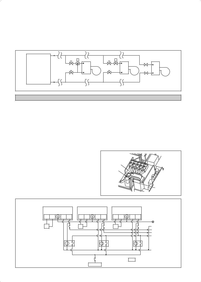
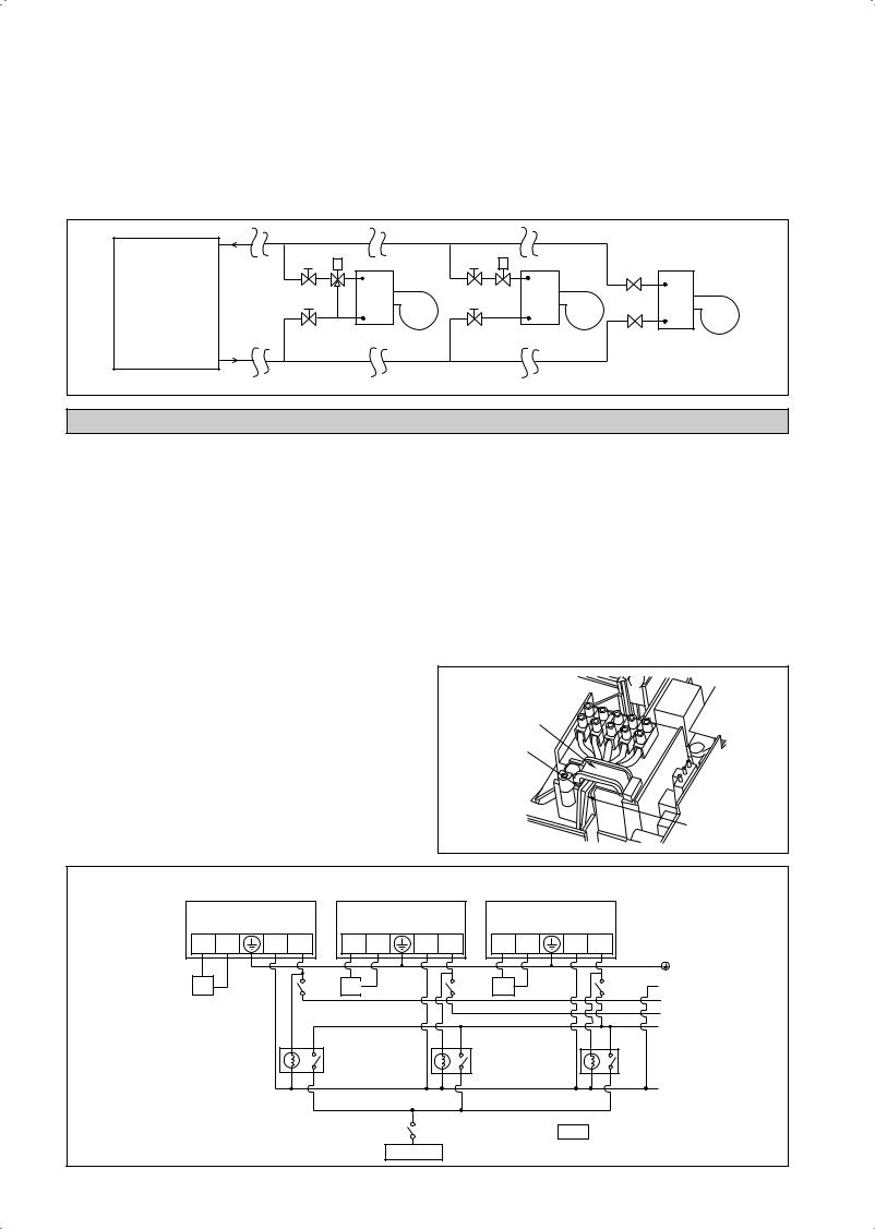
Water Piping Connection
The indoor unit is equipped with water outlet and inlet threaded connection. There is an air-vent for air purging that is fitted at the outlet water header.
3 ways valve is required for cycling off or bypass the chilled water.
Black steel pipe, polyuthrene pipe, PVC pipe and copper tube are recommended in field installation.
All types of piping and connection must be insulated by polyurethane (ARMAFLEX type or equivalent) to avoid condensation. Do not use contaminated or damaged pipe and fitting for installation.
Some main fitting components are needed in the system to enhance the capacity and ease of service, such as gate valve, balancing valve, 2 ways or 3 ways valve, filter, strainer, etc.
|
Gate Valve |
Three Way Valve |
Gate Valve |
Two Way Valve |
Gate Valve |
|
|
|
|||
|
|
|
|
|
|
Chiller |
Gate Valve |
FCU |
Gate Valve |
FCU |
FCU |
|
|
|
|||
|
|
|
|
|
Gate Valve |
|
|
Good Controlling |
|
Bad Controlling |
Worst Controlling |
ELECTRICAL WIRING CONNECTION
IMPORTANT : * These values are for information only, they should be checked and selected to comply with the local and/or national codes and regulations. They are also subjected to the type of installation and size of conductors.
**The appropriate voltage range should be checked with data label on the unit.
There must be an all pole disconnection in the supply mains with a contact separation of at least 3mm.
Model |
|
FWT02/03/04/05/06 |
|
|
|
Voltage range** |
|
220V – 240V/1Ph/50Hz + ! |
|
|
|
Power supply cable size* |
mm2 |
1.5 |
Number of conductors |
|
3 |
|
|
|
Recommended time delay fuse |
A |
2 |
|
|
|
•All wires must be firmly connected.
•All wires must not touch the water piping, or any moving parts of the fan motor.
•The connecting wires to the indoor unit must be clamped on the wire clamps as shown in the figure.
•The power supply cord must be equivalent to H07RN-F which is the minimum requirement, and to be used in protective tube.
Wire Clamp
Interconnection
Cable
Power Supply Cable
FWT02/03/04/05/06
FCU3 |
|
FCU2 |
|
|
FCU1 |
VALVE N1 |
N L |
VALVE N1 |
N L |
VALVE N1 |
N L |
3wv |
|
3wv |
|
3wv |
N |
|
|
|
|
|
T |
|
|
|
|
|
S |
|
|
|
|
|
R |
|
x1 |
|
|
x2 |
x3 |
3WV 3 way valve
x1x2x3 Relay (220-240V, 10A)
Chiller
1-6
|
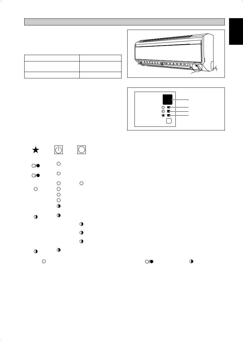
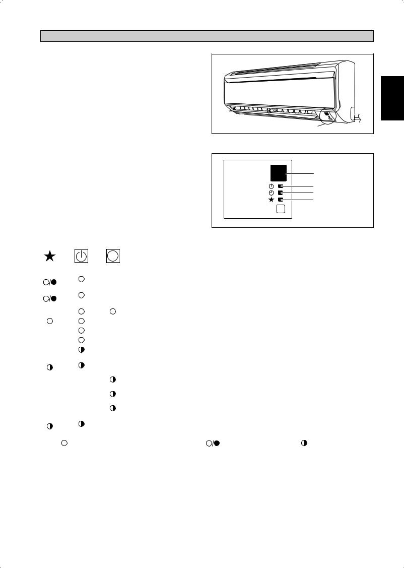
INDICATOR LIGHTS |
English |
IR Signal Receiver |
|
|
|
|
|
When an infrared remote control operating signal has been |
|
|
transmitted, the signal receiver on the indoor unit will respond |
|
|
as below to confirm acceptance of the signal transmission. |
|
|
ON to OFF |
1 Long Beep |
|
OFF to ON |
2 Short Beep |
|
Pump down/Cool force on |
|
|
Others |
1 Short Beep |
IR Receiver |
|
||
Cooling Unit/Heat Pump Unit
The table shows the LED indicator lights for the air conditioner unit under normal operation and fault conditions.
The LED indicator lights are located at the right bottom of the air conditioner unit.
LED Indicator Lights for Cooling Unit/Heat Pump Unit
IR Receiver
Cool/Heat
Timer
Sleep
ON/OFF  ON/OFF switch
LED Indicator Lights: Normal Operation And Fault Conditions For Cooling/Heat Pump Unit
|
|
|
COOL/HEAT |
|
|
|
Normal Operation/Fault Indication |
Action |
Error Code |
|
|
|
|
|
|
||||
|
|
|
|
|
|
||||
|
|
|
|
|
|
|
|
|
|
|
|
|
(GREEN/RED) |
|
|
|
|
|
|
|
|
|
|
|
|
|
|
|
|
|
|
|
Green |
|
|
|
Cool mode |
- |
- |
|
|
|
|
|
|
|
|
|
|
|
|
|
|
|
|
|
|
|
|
|
|
|
Red |
|
|
|
Heat mode |
- |
- |
|
|
|
|
|
|
|
|
|
|
|
|
|
|
|
|
|
|
|
|
|
|
|
|
|
|
|
Timer on |
- |
- |
|
|
|
|
|
|
|
|
|
|
|
|
|
|
|
|
|
Sleep mode on |
- |
- |
|
|
|
|
|
|
|
|
|
|
|
|
|
|
|
|
|
Fan mode on |
- |
- |
|
|
|
|
|
|
|
|
|
|
|
|
|
|
|
|
|
Dry mode on |
- |
- |
|
|
|
|
|
|
|
|
|
|
|
|
|
|
|
|
|
Room air sensor contact |
Call your dealer |
Blink E1 |
|
|
|
1 time |
|
|
|
Loose/Short |
||
|
|
|
|
|
|
|
|
||
|
|
|
2 times |
|
|
|
Indoor coil sensor open/short |
Call your dealer |
Blink E2 |
|
|
|
|
|
|
|
|
|
|
|
|
|
|
3 times |
Pipe water temperature poor |
- |
Blink E4 |
||
|
|
|
|
|
|
|
|||
|
|
|
|
|
|
|
|
|
|
|
|
|
|
|
1 time |
Pipe water temperature bad |
- |
Blink E5 |
|
|
|
|
|
|
|
|
|
||
|
|
|
|
6 times |
Hardware error (tact switch pin short) |
Call your dealer |
Blink E8 |
||
|
|
|
|
|
|
|
|||
|
|
|
|
|
|
|
|
|
|
|
|
|
4 times |
|
|
|
No feedback from indoor fan |
Call your dealer |
Blink E9 |
|
|
|
|
|
|
|
|
|
|
|
|
ON |
|
|
|
ON or OFF |
Blinking |
||
1-7
AIR CONDITIONER UNIT OPERATION
Dry Mode
•When the air humidity is high, the unit can operate in dry mode. Press <MODE> button and choose <DRY>.
•If the room temperature is 2°C/3.6°F higher than the set temperature, the air conditioner will operate under cooling mode until it reaches within the 2°C/3.6°F range of difference compared to the set temperature before it converts to dry mode.
•If the room temperature is within the 2°C/3.6°F range of difference compared to the set temperature, it will directly operate under dry mode.
•The unit will operate at LOW speed under dry mode.
Heat Mode (for heat pump unit only)
•When the unit at cold draft setting, the indoor fan will start to operate only after the coil reaches the desired temperature.
•For fan mode setting, indoor fan will continuous running once unit ON.
•When the set temperature is achieved, the indoor fan will operate until the coil cannot provide anymore additional heat.
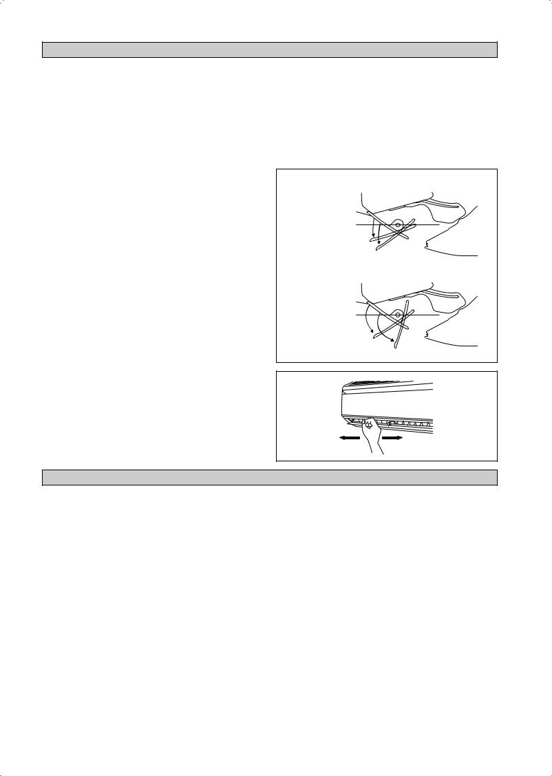
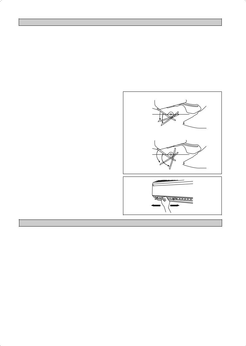
Air Flow Control
•For more effective air circulation, you can manually adjust the air discharge grille to the left or right.
•During cool mode operation and dry mode operation, do not direct the air discharge louver downwards for too long. If operating continues in this way, condensation may occur on the louver, thus resulting in drippings.
Fan Speed And Rated Cooling Capacity
•The rated cooling capacity is provided at the HIGH fan speed.
•The cooling capacity is lower when the unit is operating at MEDIUM and LOW fan speed.
Notes On Flaps And Louvers Angles
•When “SWING button” is selected, the flaps swinging range depends on the operation mode. (See the figure.)
ATTENTION
•Always use a remote controller to adjust the flaps angle. If you attempt to move it forcibly with hand when it is swinging, the mechanism may be broken.
•Be careful when adjusting the louvers. Inside the air outlet, a fan is rotating at a high speed.
In COOL, DRY and FAN mode
When stop operation
Upper limit 55˚
Lower limit 75˚
In HEAT mode
When stop operation
Upper limit 70˚
Lower limit 110˚
OPERATING RANGE
Operating Limits:
Thermal carrier : Water
Water temperature : 4-10°C Cooling; 35-50°C Heating Maximum water pressure : 16 bar
Air temperature : (as below)
Cooling Mode
Temperature |
Ts °C/°F |
Th °C/°F |
|
|
|
|
|
Minimum indoor |
19.0 / 66.2 |
14.0 / 57.2 |
|
temperature |
|||
|
|
||
Maximum indoor |
32.0 / 89.6 |
23.0 / 73.4 |
|
temperature |
|||
|
|
Heating Mode
Temperature |
|
Ts °C/°F |
Th °C/°F |
|
|
|
|
Minimum indoor |
|
15.0 / 59.0 |
- |
temperature |
|
||
|
|
|
|
Maximum indoor |
|
27.0 / 80.6 |
- |
temperature |
|
||
|
|
|
|
Ts: Dry bulb temperature. |
Th: Wet bulb temperature. |
||
1-8
AIR FILTER
1.Open the front panel.
•Hold the panel at the recesses on the main unit
(2 recesses on right and left sides) and lift it until it stops.
Recess on main unit
2.Pull out the air filters.
•Push a little upwards the tab at the center of each air filter, then pull it down.
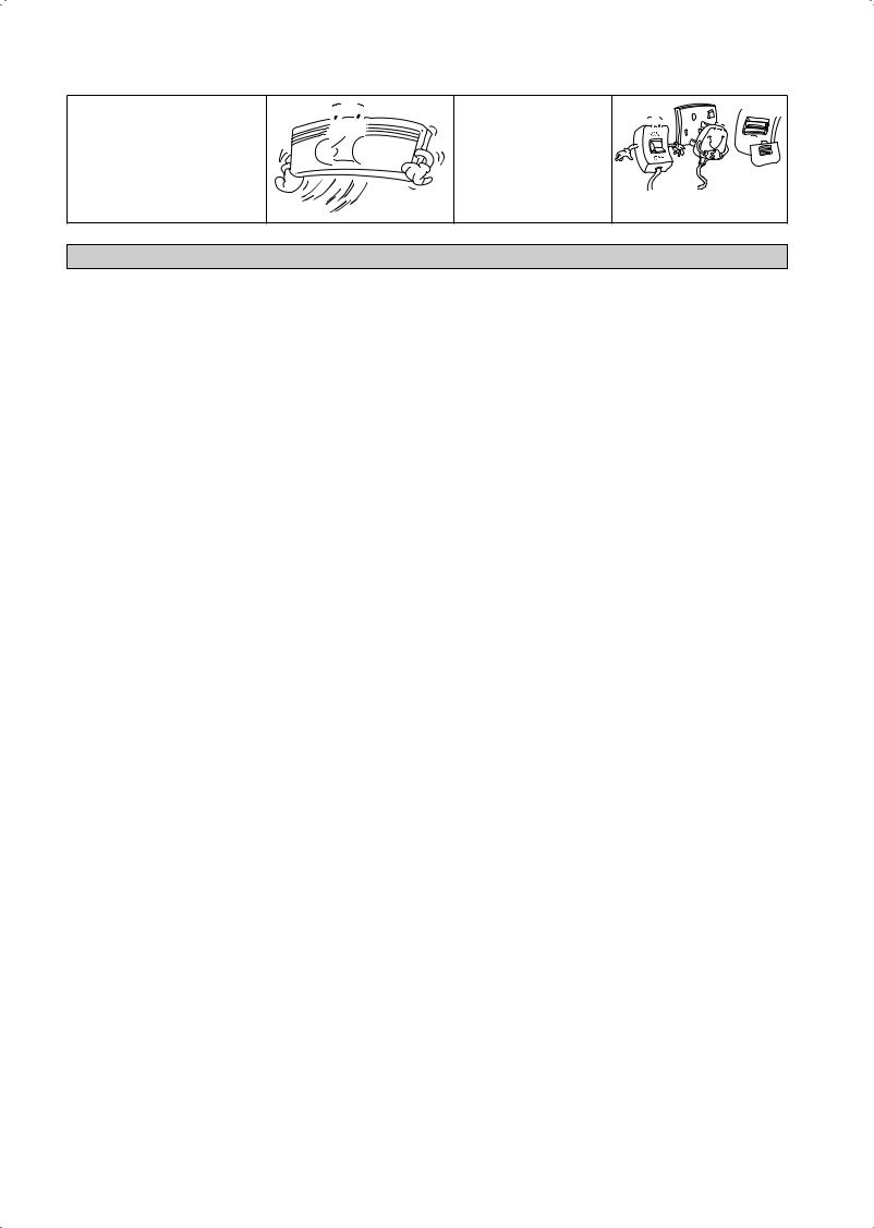
3.Clean or replace each filter.
•When shaking off remaining water, do not wring the filter.
4.Set the air filter as they were and close the front
panel.
•Insert claws of the filters into slots of the front panel. Close the front panel slowly and push the panel at the 3 points. (1 on each side and 1 in the middle.)
•The air filter have a symmetrical form in the horizontal direction.
|
|
FRONT |
|
|
|
SERVICE AND MAINTENANCE |
|
Service Parts |
|
Maintenance Procedures |
|
Indoor air filter |
1. |
Remove any dust adhering to the filter by using a vacuum cleaner or wash in lukewarm |
|
|
|
water (below 40°C/104°F) with a neutral cleaning detergent. |
|
|
2. |
Rinse the filter well and dry before placing it back onto the unit. |
|
|
3. |
Do not use gasoline, volatile substances or chemicals to clean the filter. |
|
Indoor unit |
1. |
Clean any dirt or dust on the grille or panel by wiping it with a soft cloth soaked in |
|
|
|
lukewarm water (below 40°C/104°F) and a neutral detergent solution. |
|
|
2. |
Do not use gasoline, volatile substances or chemicals to clean the indoor unit. |
|
1. Open the front panel. |
|
|
|
• Hold the panel at the recesses on the main unit (2 recesses |
Recess on |
||
on right and left sides) and lift it until it stops. |
main unit |
||
|
|||
2. Remove the front panel.
•While lifting the front panel further, slide it to the right and pull it to the front side. The left rotating shaft is detached. Slide the right rotating shaft to the left and pull it to the front side to remove it.
3. Attach the front panel. |
|
• Align the right and left rotating shafts of the front panel |
Rotating |
with the grooves and push them all the way in. |
shaft |
|
•Gently close the front panel. (Push both ends and the center on the front panel.)
!CAUTION
•Don’t touch the metal parts of the indoor unit. It may cause an injury.
•When removing or attaching the front panel, support the panel securely with hand to prevent it from falling.
•For cleansing, do not use hot water above 40°C, benzine, gasoline, thinner, nor other volatile oils, polishing compound, scrubbing brushes, nor other hand stuff.
•After cleaning, make sure that the front panel is securely fixed.
English
1-9
When The Unit Is Not To Be Used For An Extended Long Period Of Time
Operate the unit for 2 hours with the following setting.
Operating mode : cool Temperature : 30°C/86°F
Remove the power plug. If you are using an independent electric circuit for your unit, cut off the circuit.
Remove the batteries in the remote control.
TROUBLESHOOTING
For any enquiries on spare part please contact your authorized dealer. When any malfunction of the air conditioner unit is noted, immediately switch off the power supply to the unit. Check the following fault conditions and causes for some simple troubleshooting tips.
|
Fault |
|
Causes / Action |
|
|
|
|
1. |
The air conditioner unit does not operate. |
– |
Power failure, or the fuse needs to be replaced. |
|
|
– The power plug is disconnected. |
|
|
|
– |
It is possible that your delay timer has been set |
|
|
|
incorrectly. |
|
|
– If the fault persist after all these verifications, please |
|
|
|
|
contact the air conditioner unit installer. |
|
|
|
|
2. |
The air flow is too low. |
– |
The air filter is dirty. |
|
|
– The doors or windows are open. |
|
|
|
– The air suction and discharge are clogged. |
|
|
|
– The regulated temperature is not high enough. |
|
|
|
|
|
3. |
Discharge air flow has bad odour. |
– |
Odours may be caused by cigarettes, smoke particles, |
|
|
|
perfume etc. which might have adhered onto the coil. |
|
|
|
|
4. |
Condensation on the front air grille of the indoor unit. |
– |
This is caused by air humidity after an extended long period |
|
|
|
of operation. |
|
|
– The set temperature is too low, increase the temperature |
|
|
|
|
setting and operate the unit at high fan speed. |
|
|
|
|
5. |
Water flowing out from the air conditioner unit. |
– |
Switch off unit and call dealer. |
|
|
|
|
If the fault persists, please call your local dealer / serviceman.
1-10
AUSLEGUNG UND ABMESSUNGEN
Innen-Gerät
DAS ZEICHEN |
|
ZEIGT DIE ANSCHLUSSRICHTUNG |
||||
|
||||||
|
|
|
|
|
A |
|
|
|
RÜCKSEITE |
RÜCKSEITE |
|||
|
|
|
|
|
|
|
LINKS
ANSICHT VON OBEN
B
BODEN |
|
BODEN |
|
GITTER |
AUF DER VORDERSEITE |
|
||
|
|
DES GITTERS BEFESTIGTE |
|
|
SCHRAUBEN (INNEN) |
|
|
VORDERANSICHT |
RECHTE
SIGNALEMPFÄNGER
GERÄT FÜR IM HAUS AN/ AUS-SCHALTER
RAUMTEMPERATUR THERMISTOR (INSIDE)
C
NAMENSSCHILD
B
ANSCHLUSSBLOCK
MIT ERDANSCHLUSS
SEITENANSICHT
 Empfohlene Haltepunkte der Montageplatte (insgesamt 5 Punkte)
D
F
B
Verwenden Sie ein Bandmaß und positionieren Sie das Ende des Bandmaßes wie dargestellt an Punkt
E
F
Wandöffnung Ø 65mm
G |
|
|
|
G |
|
|
|
|
|
H |
J |
|
K |
I |
|
L |
M |
|
Position des |
|
|
A |
|
Ablaufschlauchs |
|
Wassereintrittsöffnung |
Wasseraustrittsöffnung |
|
|
|
MONTAGEPLATTE FWT02/03/04 |
|
||
Alle dimensionen sind in mm
Übersetzung der Original-Anleitungen Deutsch
2-1
Empfohlene Haltepunkte der Montageplatte |
|
|
|
|
|
|
|
|
|
|
||||
(insgesamt 7 Punkte) |
|
|
|
|
|
|
|
|
|
|
|
|
|
|
|
D |
|
|
|
|
|
|
|
|
E |
|
|
|
|
F |
|
|
|
|
|
|
|
|
|
|
|
F |
|
|
B |
|
|
|
|
|
|
|
|
|
|
|
|
|
|
|
|
|
|
|
|
|
|
|
|
|
|
Wandöffnung |
|
|
|
|
|
|
|
|
|
|
|
|
|
|
Ø 65mm |
|
|
G |
|
|
|
|
|
|
|
|
|
|
|
G |
|
|
H |
J |
Wassereintrittsöffnung |
|
Wasseraustrittsöffnung |
K |
|
I |
Position des |
|
|||||
M |
|
Ablaufschlauchs |
|
|||||||||||
|
|
|
L |
|
|
|
|
|
|
|
|
|||
|
|
|
|
A |
|
|
|
|
|
|
|
|
||
|
|
|
|
|
|
|
|
|
|
|
|
|
|
|
|
|
|
|
MONTAGEPLATTE FWT05/06 |
|
|
Alle dimensionen sind in mm |
|||||||
|
|
|
|
|
|
|
|
|
|
|||||
Abmessung |
A |
B |
C |
D |
E |
F |
G |
H |
I |
J |
K |
L |
M |
|
Modell |
|
|||||||||||||
|
|
|
|
|
|
|
|
|
|
|
|
|
|
|
FWT02/03/04 |
|
800 |
288 |
206 |
166 |
184 |
42 |
46 |
55 |
56 |
154 |
182 |
267 |
55 |
FWT05/06 |
|
1065 |
310 |
224 |
190 |
173 |
61 |
40 |
45 |
48 |
91 |
219 |
593 |
60 |
2-2
INSTALLATIONSHANDBUCH
Das vorliegende Handbuch enthält die Installationsanweisungen für einen sicheren und ordnungsgemäßen Betrieb dieser Anlage. Je nach den örtlichen Gegebenheiten können spezielle Anpassungen notwendig sein.
Vor der Inbetriebnahme des Klimagerätes dieses Handbuch bitte aufmerksam zur Kenntnis nehmen und für künftigen Bedarf aufbewahren. Dieses Gerät für den Betrieb durch Fachleute oder geschulte Benutzer in Geschäften, der Leichtindustrie und in landwirtschaftlichen Betrieben sowie für gewerbliche Zwecke durch Laien ausgelegt.
Das Gerät ist nicht konzipiert, um von folgenden Personengruppen einschließlich Kindern benutzt zu werden: Personen mit eingeschränkten körperlichen, sensorischen oder geistigen Fähigkeiten oder Personen mit mangelhafter Erfahrung oder Wissen, es sei denn, sie sind von einer Person, die für ihre Sicherheit verantwortlich ist, darin unterwiesen worden, wie das Gerät ordnungsgemäß zu verwenden und zu bedienen ist. Kinder sollten beaufsichtigt werden, um sicher zu sein, dass sie nicht mit dem Gerät spielen.
VORSICHTMASSNAHMEN
!ACHTUNG
•Die Installation und Wartung muß durch qualifizietes Personal erfolgen, Welches mit den örtlichen Bestimmungen und diesem Ausrüstungstyp vertraut ist.
•Die gesamte E-Verkabelung hat in Übereinstimmung mit den landesspezifischen Anschlußvorschriften zu erfolgen.
•Vor dem Kabelanschluß gemäß Schaltbild ist sicherzustellen, daß die Betriebsspannung mit der auf dem Datenschild des Gerätes angegebenen Spannung übereinstimmt.
•Das Gerät ist zum Schutz gegen fehlerhafte Isolierungen und entsprechende Risiken zu ERDEN.
•Die Kabel dürfen weder mit der Kühlmittelleitung, noch mit den beweglichen Teilen der Gebläsemotoren in Berührung kommen.
•Vor der Installation oder Wartung der Anlage ist sicherzustellen, daß das Gerät ausgeschaltet ist (OFF).
•Ziehen Sie vor der Wartung der Klimaanlage den Stecker aus der Steckdose.
•NICHT das Stromkabel herausziehen, wenn das Gerät noch eingeschaltet ist. Ein elektrischer Schlag oder ein Wohnungsbrand kann die Folge sein.
•Halten Sie Innenund Außengerät mindestens 1m entfernt von Fernsehern und Rundfunkgeräten, um verzerrte Bilder und statische Entladungen zu vermeiden. {abhängig von Type und Quelle der elektrischen Wellen, können statische Entladungen auch noch hörbar sein bei Abständen von mehr als 1m}.
!VORSICHT
Vor der Installation sind folgende wichtige Punkte zu prüfen.
•Die Kondensat-Abflußleitung muß sachgemäß angeschlossen sein.
Ist dieAbflußleitung nicht richtig angeschlossen, besteht Gefahr, daß durch auslaufendes Wasser das Mobiliar feucht wird.
•Nach Installation oder Wartung ist sicherzustellen, daß die Geräteabdeckung wieder montiert ist.
Eine mangelhafte Befestigung der Abdeckung führt zu Geräuschentwicklung während des Betriebs.
•Scharfe Kanten und Wärmetauscherflächen stellen eine Gefahrenquelle dar.
Jeglicher Kontakt mit diesen Stellen ist zu vermeiden.
•VorAbschalten der Stromzufuhr muss der ON/OFFSchalter der Fernbedienung auf „OFF“ gestellt werden, um eine versehentliche Fehleinstellung zu vermeiden. Andernfalls schaltet sich bei Wiederherstellung der Stromzufuhr das Kühlgebläse automatisch wieder ein und kann somit für den Benutzer oder Wartungspersonal ein unerwartetes Risiko darstellen.
•Die Geräte dürfen nicht bei oder in der Nähe von Türen installiert werden.
•Betreiben Sie keine Heizgeräte in direkterNähe des Klimagerätes, und verwenden Sie das Gerät nicht in Räumen, in denen es Mineralölen, Öldämpfen oder -nebel ausgesetzt ist, da dies zu einem Schmelzen oder einerVerformung der Plastikbestandteile aufgrund von Hitze oder chemischer Reaktion führen könnte.
•Sollte das Gerät in einer Küche eingesetzt werden, so achten Sie bitte darauf, dass kein Mehlstaub eingesaugt werden kann.
•Dieses Gerät ist nicht fürden Einsatz in Fabriken geeignet, in denen es zur Entwicklung von Öldämpfen oder Eisenstaub kommt, bzw. In denen es zu starken Stromschwankungen kommen kann.
•Das Gerät eignet sich nicht zur Installation in der Nähe von Heißquellen oder Raffinerien, wo Sulfidgase entstehen können.
•Sorgen Sie dafür, dass die Farben der Drähte des Außengerätes und der Anschlussmarkierungen dieselbe sind wie die Übereinstimmende des Innengerätes.
•WICHTIG: DAS KLIMAGERÄT SOLLTE NICHT IN EINEM WÄSCHERAUM INSTALLIERT ODER BENUTZT WERDEN.
•Verwenden Sie zur Stromversorgung keine zusammengefügten und geknickte Kabel.
•Das Gerät ist nicht zur Verwendung in einer potentiell explosiven Atmosphäre konzipiert.
BEMERKUNG
Vorschriften zur entsorgung
Ihre Klimaanlage ist mit diesem Symbol gekennzeichnet. Das bedeutet, dass elektrische und elektronische Produkte nicht mit unsortiertem Haushaltsabfall entsorgt werden dürfen.
Versuchen Sie auf keinen Fall das System selbst zu demontieren: Die Demontage des Klimaanlagensystems sowie die Handhabung von 
 Kältemittel, Öl und möglichen weiteren Teilen muss von einem qualifizierten Monteur gemäß den entsprechenden örtlichen und staatlichen
  Bestimmungen vorgenommen werden.
Klimaanlagen müssen bei einer fachkundigen Einrichtung für Wiederverwendung, Recycling und Wiedergewinnung aufbereitet werden. Indem Sie dieses Produkt korrekt entsorgen, helfen Sie potenzielle negative Folgen für die Umwelt und die Gesundheit der Menschen zu vermeiden. Nehmen Sie bitte hinsichtlich weiterer Informationen Kontakt auf mit dem Monteur oder den örtlichen Behörden.
Die Batterien müssen aus der Fernbedienung entfernt werden und gemäß den entsprechenden örtlichen und staatlichen Vorschriften separat entsorgt werden.
2-3
Deutsch

INSTALATIONSDIAGRAMM
VOLLSTÄNDIG ISOLIERTES KORK-BAND
ISOLIERUNG ÜBER DIE KÜHLWASSERLEITUNG
INSTALLATION DES INNENGERÄTES
Innengeräte sind so zu installieren, daß keine Interferenz zwischen dem Kühlluftaustritt und der zurückgeführten Luft besteht. Bei der Installation bitte die in der Zeichnung angegebenen Abstände beachten. Ein Innenmontage-Gerät darf nicht unter direkter Sonneneinstrahlung montiert werden. Die Montageposition ist anhand der Rohrleitung und der Drainage im gegebenen Abstand zu Türen oder Fenstern zu gewährleisten.
Luftstrom |
|
|
|
|
(Im Haus) |
|
min. 30 (Platz für |
Leistung) |
|
|
|
|||
min. 50 |
Erforderlicher Platz |
min. 50 |
|
|
(Platz für |
||||
(Platz für Wartung) |
||||
|
||||
|
Wartung) |
|||
|
|
|||
|
Alle dimensionen sind in mm |
|||
!VORSICHT
Das Gerät nicht in einer Höhe über 2000m installieren.
Luftevakuierung
Um Schäden an der Pumpe zu vermeiden, sollte die Ventilatorspule nicht unter Spannung gesetzt werden, bis die Spule und alle Wasserleitungen von Luft befreit wurden.
Die Wasserleitung kann auf verschiedene Weise an das Gerät angeschlossen werden. (links oder rechts an der Rückseite des Gerätes). Verwenden Sie hierzu die Aussparungen in der Gërateverkleidung, (sieheAbb), und biegen Sie die Rohre vorsichtig auf die entsprechenden Lochpositionen. Halten Sie bei einem Seitenoder Bodenausgang den unteren Teil des Rohres fest und bringen Sie ihn in die gewünschte Richtung (siehe Abb). Sie können den Kondensatschlauch mit Klebeband an den Rohren fixieren.
Anschluss der Rohre seitlich rechts, hinten rechts oder unten rechts
Verrohrung rechts
Entfernen Sie die
Verrohrungsabdeckung hier für
Verrohrung an der rechten Seite Verrohrung rechts unten
Entfernen Sie die Verrohrungsabdeckung hier für Verrohrung rechts unten
Verrohrung rechts hinten
Binden Sie das Kühlmittelrohr und den Ablaßschlauch mit Isolierband zusammen.
Rohranschluss Seitlich links, Rückseite links oder Unten links
Entfernen Sie die Verrohrungsabdeckung hier für Verrohrung links unten
Entfernen Sie die Verrohrungsabdeckung hier für Verrohrung an der linken Seite
Verrohrung  links
links
Verrohrung links hinten
Verrohrung links unten
Der Belüftungsschlitz, der sich im Inneren des Gehäuses befindet. Entfernen Sie das Gehäuse, und schließen Sie den Schlauch an den Belüftungsschlitz an, während Sie die Luftevakuierung durchführen.
!VORSICHT
Stellen Sie sicher, dass während des Luftevakuierungsprozesses keine Wassertröpfchen in den Steuerkasten gelangen.
2-4
Montage der Installations-halterungsplatte
Sicherstellen, daß die Trägerwand ausreichend fest ist, um das Gewicht aufnehmen zu können. Falls nicht, müssen geeignete Vertärkungsplatten, Träger oder Stützen verwendet werden.
Verwenden Sie eine Wasserwaage für eine waagerechte Halterung und befestigen Sie es mit 5 geeigneten Schrauben für FWT02/03/04 und mit 7 geeigneten Schrauben für FWT05/06.
Bei Rohrleitungs-herausführung auf der Rückseite: Eine Bohrung 65mm mit einem Konusbohrer setzen. Hierbei die Bohrung auf der wandungsaußenseite etwas tiefer positionieren (siehe Abb).
FWT02/03/04 |
Befestigungsblech |
|
Befestigungsschraube
Montageplatte
Bohrung Durch Konusbohrer
Innen |
Außen |
|
Wanddurchbruchrohr |
Abdichtung |
|
(bauseits beizustellen) |
||
|
||
Wandblende |
Ø 65 |
|
|
||
(bauseits beizustellen) |
Wanddurchbruchrohr |
|
|
||
|
(bauseits beizustellen) |
Gerätemontage Auf Der Installationsplatte
Innenmontage-Gerät in den oberen Bereich der Installationsplatte einhängen (Die beiden hinteren oberen Laschen der Innenmontage-Einheit in die obere Kante der Installationsplatte einhängen). Bewegen Sie die Montageplatte leicht nach links und rechts, um zu prüfen, ob die Haken ordnungsgemäß eingegriffen haben.
Anbringen des Innenaggregats
Haken Sie die Klemmen des Bodenrahmens auf der montageplatte ein.
Entfernen des Innenaggregats
Drücken Sie den markierten Bereich (am unteren Teil des Frontgrills) nach oben, um die Klemmen zu lösen.
FWT05/06
 Befestigungsblech
Befestigungsschraube 
Montageplatte
Empfohlene Montageplatte, Halterungsstellen und Abmessungen
FWT02/03/04
Empfohlene Haltepunkte |
|
Verwenden Sie ein Bandmaß und |
||
der Montageplatte |
|
positionieren Sie das Ende des |
||
(insgesamt 5 Punkte) |
|
Bandmaßes wie dargestellt an Punkt |
||
|
166 |
|
184 |
|
42,2 |
|
|
|
42,2 |
288 |
|
|
|
Wandöffnung |
|
|
|
|
|
|
|
|
|
Ø 65mm |
45,9 |
|
|
181,7 |
45,9 |
54,5 |
153,8 |
|
55,5 |
|
|
263 |
51,9 |
800 |
Position des |
|
Wassereintrittsöffnung |
Wasseraustrittsöffnung |
Ablaufschlauchs |
|
|
|
|||
Alle dimensionen sind in mm
FWT05/06 |
|
|
|
|
|
|
Empfohlene Haltepunkte der Montageplatte |
|
|
|
|||
(insgesamt 7 Punkte) |
|
|
|
|
||
|
190 |
|
|
173 |
|
|
61 |
|
|
|
|
|
61 |
310 |
|
|
|
|
|
Wandöffnung |
|
|
|
|
|
|
|
|
|
|
|
|
|
Ø 65mm |
40 |
|
|
|
|
|
40 |
45 |
91 |
Wassereintrittsöffnung |
Wasseraustrittsöffnung |
219 |
48 |
Position des |
|
|
580 |
45 |
|
|
Ablaufschlauchs |
|
|
|
1065 |
|
|
|
|
|
|
|
|
|
|
|
|
|
Alle dimensionen sind in mm |
|||
Befestigungsblech
|
Clip |
|
Vorderes Gitter |
Unterer Rahmen |
|
Markierung |
||
|
(Rückseite) |
|
|
Die Inneneinheit hier einhaken. |
|
Wenn die Enden der |
Befestigungsblech |
|
Verbindungsdrähte |
|
|
im voraus abisoliert |
|
|
werden, so binden Sie |
Verbindungsdrähte |
|
die Drahtenden mit |
||
|
||
Isolierband zusammen. |
|
|
|
Drahtführung |
Wasser-Entleerungsleitung
Zur problemlosen Kondensatabführung muß die innenliegende Wasserentleerungsleitung Gefälle aufweisen. Vermeiden Sie Umstände, die zum Austreten von Wasser führen können.
Wasserablauf
|
|
Wasserrückhaltung |
In Wasser |
|
|
|
|
||
Wasser |
Wasser |
Wasser |
Eintau- |
|
Chendes |
||||
Leck |
Leck |
Leck |
||
Rohrende |
||||
|
|
|
Ableitung
Korrekt |
Falsch |
Falsch |
Falsch |
Deutsch
2-5
Wasserleitungsanschluss
Das Gerät für im Haus ist mit einem Anschlussgewinde für Wasserabund –zufluss ausgestattet. Es besitzt eine Entlüftung für Luftaustausch, die auf dem Wasserzufluss-Kopf montiert ist.
Ein 3-Wege Ventil wird benötigt, um das gekühlte Wasser aboder umzuleiten.
Wir empfehlen für im Freien, eine schwarze Stahlleitung, Polyuthren-Leitung, PVC-Leitung und Kupferleitung zu verlegen.
Alle Arten von Leitungen und Verbindungen müssen mit Polyurethan (äquivalent zum ARMAFLEX Typ) isoliert werden, um Kondensierungen zu vermeiden. Verwenden Sie bei der Installation keine verschmutzen oder beschädigten Leitungen.
Einige HauptanschlussKomponenten werden innerhalb des Systems benötigt, um die Kapazität und Wartung zu erleichtern, wie etwa bei Absperrhahn, Ausgleichsventil, 2-Wege oder 3-Wege Ventil, Filter, Siebkörper etc.
|
Schieber |
3-Weg Ventil |
Schieber |
2-Weg Ventil |
|
|
|
|
Schieber |
||
|
|
|
|
|
|
Kühler |
Schieber |
FCU |
Schieber |
FCU |
FCU |
|
|
|
|
|
Schieber |
|
|
Gutes Controlling |
Schlechtes Controlling |
Sehr Schlechtes Controlling |
|
KABELANSCHLUß
WICHTIG : * Die in der Tabelle aufgeführten Daten sind als reine Information zu verstehen und sollten daher geprüft und so ausgewählt werden, dass sie den örtlichen/nationalen Bestimmungen entsprechen. Außerdem hängt diese von der Art der Installation und der Größe der Leitern ab.
**Der geeignete Spannungsbereich sollte den Etikettdaten auf der Einheit entnommen werden.
In dem Hauptversorgungsnetz muss eine Unterbrechung aller Pole vorhanden sein, mit einem Kontaktunterbrecher von mindestens 3mm.
Modell |
|
FWT02/03/04/05/06 |
|
|
|
Spannungsbereich** |
|
220V – 240V/1Ph/50Hz + ! |
|
|
|
Zuleitungskabelquerschnitt* |
mm2 |
1,5 |
Adernanzahl |
|
3 |
|
|
|
Empfohlene Sicherung |
A |
2 |
|
|
|
•Alle Adern sind fest zu verdrahten.
•Jeglicher Kontakt einer Elektrokabelader mit der Kältemittelleitung, dem Kompressor oder anderen beweglichen Teilen des Gebläsemotors ist zu vermeiden.
•Die anschließenden Leitungen zur Innenmaßeinheit müssen auf den Leitung Klemmplatten festgeklemmt werden, wie in der Abbildung gezeigt worden.
•Das Stromkabel muss gleichwertig sein mit H07RN-F was die Mindestforderung ist, und muss in einem Schutzrohr verlegt werden.
Drahtklemme
Verbin-Dungskabel
Anschluss-Kabel
FWT02/03/04/05/06
FCU3 |
|
FCU2 |
|
|
FCU1 |
VALVE N1 |
N L |
VALVE N1 |
N L |
VALVE N1 |
N L |
3wv |
|
3wv |
|
3wv |
N |
|
|
|
|
|
T |
|
|
|
|
|
S |
|
|
|
|
|
R |
|
x1 |
|
|
x2 |
x3 |
|
3WV |
3-wege-ventil |
Kühler |
x1x2x3 |
Relais (220-240V, 10A) |
|
|
2-6
BETRIEBSLEUCHTANZEIGE
Infrarot-Signalempfänger
Wurde über die Fernbedienung ein Infrarot-Signal gesendet, so antwortet der Signalempfänger des Gerätes für im Haus wie unten angegeben und bestätigt den Signalempfang.
AN auf AUS |
1 langer Piepston |
AUS auf AN |
2 kurze Piepstöne |
Hinunterpumpen/Kühlung |
|
eingeschaltet |
|
Andere |
1 kurze Piepstöne |
|
|
Kühleinheit/Wärmepumpe
Nachstehende Tabelle enhält die einzelnen LEDFunktionsanzeigen für Normalbetrieb und die verschiedenen Störungsmeldungen.
Die LEDs befinden sich rechts unten an der Klimaanlage.
Deutsch |
Infrarot-Empfanger |
Leuchtdiode für Kühlbetrieb/Wärmepumpe |
Infrarot-Empfanger
Kühl/Heiß
Timer (Zeiteinstellung)
Sleep (Schlummerfunktion)
ON/OFF  EIN-/AUS-Schalter
Leuchtdioden : Normalbetrieb und Störungssituationen des Kühlgeräts / Wärmepumpe
|
|
|
KÜHLEN SIE AB/HITZE |
|
|
|
Normalbetrieb und Störungssituationen |
Maßnahme |
Fehlermeldung |
|
|
|
|
|
|
||||
|
|
|
|
|
|
||||
|
|
|
|
|
|
|
|
|
|
|
|
|
(GRÜN/ROT) |
|
|
|
|
|
|
|
|
|
|
|
|
|
|
|
|
|
|
|
Grün |
|
|
|
Kühlmodus |
- |
- |
|
|
|
|
|
|
|
|
|
|
|
|
|
|
|
|
|
|
|
|
|
|
|
Rot |
|
|
|
Heiz-Modus |
- |
- |
|
|
|
|
|
|
|
|
|
|
|
|
|
|
|
|
|
|
|
|
|
|
|
|
|
|
|
Zeitschalter an |
- |
- |
|
|
|
|
|
|
|
|
|
|
|
|
|
|
|
|
|
Schlafmodul an |
- |
- |
|
|
|
|
|
|
|
|
|
|
|
|
|
|
|
|
|
Ventilatormodus eingeschaltet |
- |
- |
|
|
|
|
|
|
|
|
|
|
|
|
|
|
|
|
|
Trocknungsmodus eingeschaltet |
- |
- |
|
|
|
|
|
|
|
|
|
|
|
|
|
|
|
|
|
Raum-Luftsensorkontakt unterbrochen/ |
Händler benachrichtigen |
E1 blinkt |
|
|
|
1 mal |
|
|
|
kurzgeschlossen |
||
|
|
|
|
|
|
|
|
||
|
|
|
2 male |
|
|
|
Sensor des Innen-Ventilators öffnet /kurzgeschlossen |
Händler benachrichtigen |
E2 blinkt |
|
|
|
|
|
|
|
|
|
|
|
|
|
|
|
|
|
|
|
|
|
|
|
|
3 male |
Die Temperatur des Rohrwassers ist niedrig |
- |
E4 blinkt |
||
|
|
|
|
|
|
|
|||
|
|
|
|
|
|
|
|
|
|
|
|
|
|
1 male |
Die Temperatur des Rohrwassers ist schlecht |
- |
E5 blinkt |
||
|
|
|
|
|
|
|
|||
|
|
|
|
|
|
|
|
|
|
|
|
|
|
|
|
|
Hardware-Fehler (Nadel des Takt-Schalters schließt |
Händler benachrichtigen |
E8 blinkt |
|
|
|
|
6 male |
kurz) |
||||
|
|
|
|
|
|
||||
|
|
|
4 male |
|
|
|
Keine Rückmeldung des Ventilators im Haus |
Händler benachrichtigen |
E9 blinkt |
|
|
|
|
|
|
|
|
|
|
|
|
|
|
|
|
|
|
|
|
|
|
|
AUF |
EIN oder AUS |
Blinkend |
||||
2-7
BEDIENUNG DES KLIMAGERÖTES
Entfeuchten
•Bei hoher Luftfeuchtigkeit ist das Gerät zum Entfeuchteneinsetzbar. Dazu die <MODE>-Taste betätigen und <DRY> anwählen.
•Liegt die Raumtemperatur um 2°C/3,6°F höher als die eingestellte Temperatur, arbeitet das Gerät im Kühlbetrieb, bis die Raumtemperatur sich innerhalt von 2°C/3,6°F Unterschied gegenüber der eingestellten Temperatur befindet, und schaltet anschließend auf Entfeuchten um.
•Liegt die Raumtemperatur innerhalb von 2°C/3,6°F Unterschied gegenüber der eingestellten Temperatur, schaltet sich das Gerät direkt auf Entfeuchtung.
•Bei Entfeuchtung arbeitet das Gerät mit LANGSAMER Gebläsedrehzahl.
Heizbetrieb (nur für Wärmepumpe)
•Wenn das Gerät auf kalte Luftströmung eingestellt ist, setzt das Gebläse am Innengerät sich erst in Gang, wenn der Wärmetauscher die gewünschte Temperatur erreicht hat.
•Bei Einstellung des Gebläsemodus wird das Gebläse am Innengerät kontinuierlich laufen, sobald das Gerät auf ON gestellt ist.
•Ist die eingestellte Temperatur erreicht, arbeitet das Innengebläse so lange, bis der Wärmetauscher seine maximale Heizkapazität erreicht hat.
Luftstromsteuerung
•Zur verbesserten Luftzirkulation kann das Abluftgitter nach links oder rechts mit der Hand verstellt werden.
•Während der KÜHLoder ENTFEUCHTUNGS-Funktion (COOLING/DRY) solte das Strömungsrichtungsgitter nicht über einen längeren Zeitraum hin direkt nach unten gerichtet werden. Bei einer Kondensatbildung kann es dadurch zu einer Tropfenbildung kommen.
Gebläsedrehzahl und vorgesehene Kühlleistung
•Die vorgesehene Kühlleistung wird bei einer HOHEN Gebläsedrehzahl erreicht.
•Bei mittlerer bzw. langsamer Gebläsedrehzahl liegt die Kühlleistung niedriger.
Hinweise zu Winkeln der Schwenkklappen und Lüftungsgitter
•Der Schwenkbereich der Klappen bei Drücken der Taste „SCHWENKEN“ ist von der Betriebsart abhängig. (Siehe Abbildung.)
ACHTUNG
•Benutzen Sie immer die Fernbedienung, um den Klappenwinkel einzustellen. Wenn Sie versuchen ihn gewaltsam mit der Hand zu verändern während die Klappe schwingt, können Sie den Mechanismus beschädigen.
•Gehen Sie beim Einstellen der Lüftungsgitter vorsichtig vor. Auf der Innenseite der Luftaustrittsöffnung dreht sich mit hoher Geschwindigkeit ein Ventilator.
Im KÜHL, ENTFEUCHTER, und VENTILATOR
Bei Betriebsstopp
Obergrenze 55°
Untergrenze 75°
Im HEIZ
Bei Betriebsstopp
Obergrenze 70°
Untergrenze110°
BETRIEBSBEREICH
Grenzwerte für den Betrieb:
Wärmeträger : Wasser
Wassertemperatur : 4-10°C Kühlen, 35-50°C Heizen Maximaler Wasserdruck : 16 bar
Lufttemperatur : (siehe hier unten)
Kühlender Modus
Temperatur |
Ts °C/°F |
Th °C/°F |
|
|
|
|
|
Mindest- |
19,0 / 66,2 |
14,0 / 57,2 |
|
Innentemperatur |
|||
|
|
||
Maximale- |
32,0 / 89,6 |
23,0 / 73,4 |
|
Innentemperatur |
|||
|
|
||
|
|
|
Heizung Modus
Temperatur |
Ts °C/°F |
Th °C/°F |
|
|
|
|
|
Mindest- |
15,0 / 59,0 |
- |
|
Innentemperatur |
|||
|
|
||
Maximale- |
27,0 / 80,6 |
- |
|
Innentemperatur |
|||
|
|
||
|
|
|
Ts: Trockenkugel-Temperatur. |
Th: Feuchtkugeltemperatur. |
2-8
LUFTFILTER
1.Öffnen der Frontplatte.
•Halten Sie die Platte an den Vertiefungen des Hauptgerätes (2 Vertiefungen auf der rechten undlinken Seite), und heben Sie sie bis zum Anschlag an.
Aussparung am
Hauptgerät
2.Ziehen Sie die Luftfilter heraus.
•Drücken Sie den Griff in der Mitte jedes Filters nach oben, ziehen Sie ihn dann nach unten heraus.
3.Reinigen oder ersetzen Sie alle Filter.
•Beim Abschütteln des restlichen Wassers den Filter nicht auswringen.
4.Stellen Sie den Luftfilter in die ursprüngliche Einstellung zurück und schließen Sie den Deckel auf der Vorderseite.
•Setzen Sie die Klemmen der Filter in die Schlitze der Frontplatte ein. Schließen Sie das Frontplatte langsam und drücken Sie das Platte an den 3 Punkten. (1 aufjeder Seite und 1 in der Mitte.)
•Der Luftfilter besitzt in der horizontalen Richtung eine symmetrische Form.
|
|
FRONT |
|
|
|
INSTANDHALTUNG UND WARTUNG |
|
Wartungsteile |
|
Wartungsverfahren |
|
Luftfilter |
1. |
Luftfilter mit Staubsauger absaugen oder in lauwarmem Wasser (unter 40°C/104°F) mit neutraler |
|
Innen-Gerät |
|
Seife auswaschen. |
|
|
2. |
Sorgfältig ausspülen und vor dem Wiedereinsetzen trocknen. |
|
|
3. |
Kein Benzin, Verdünner oder Chemikalien verwenden, um den Filter zu reinigen. |
|
Innen-Gerät |
1. |
Staub oder Schmutz an Gitter und Abdeckung mit einem weichen Tuch abwischen. Das Tuch |
|
|
|
vorher in lauwarmem Wasser (unter 40°C/104°F) mit neutraler Seife anfeuchten. |
|
|
2. |
Kein Benzin, noch Verdünner oder sonstige Chemikalien zum Reinigen des Innengeräts verwenden. |
|
1. Öffnen der Frontplatte. |
Aussparung |
||
• Halten Sie die Platte an den Vertiefungen des Hauptgerätes |
am Hauptgerät |
||
|
|||
(2 Vertiefungen auf der rechten und linken Seite), und |
|
||
heben Sie sie bis zum Anschlag an. |
|
||
2. Abnehmen der Frontplatte. |
|
• Während Sie die Frontplatte weiter anheben, schieben |
|
Sie sie nach rechts, und ziehen Sie sie zur Vorderseite. |
|
Die linke Drehachse wird gelöst. Schieben Sie die rechte |
|
Drehachse nach links, und ziehen Sie sie zum Abnehmen |
|
zur Vorderseite. |
Drehachse |
3.Anbringen der Frontplatte.
•Richten Sie die rechte und linke Drehachse der Frontplatte auf die Nuten aus, und drücken Sie sie bis zum Anschlag
hinein. 


•Die Frontplatte sachte schließen. (Beide Seiten und die  Mitte der Frontplatte andrücken.)
!VORSICHT
•Berühren Sie nicht die Metallteile des Innengerätes. Sie können sich verletzen.
•Stützen Sie das Frontplatte beim Ausund Einbau fest mit einer Hand, damit es nicht herunterfällt.
•Verwenden Sie zum Reinigen kein heißes Wasser mit einer Temperatur von mehr als 40°C ist, kein Waschbenzin oder Benzin, keinen Verdünner oder andere verdunstende Öle, Poliermittel, Scheuerbürsten oder andere harte Gegenstände.
•Vergewissern Sie sich nach dem Reinigen, dass das Frontplatte sicher befestigt wurde.
Deutsch
2-9

Bei Längerer Nichtbenutzung Des Klima-Gerätes
Betreiben Sie das Gerät 2 stunden lang in folgender.
Einstellung Betriebsmodus : kühlen Temperatur : 30°C/86°F
Netzstecker ziehen. Falls das Klimagerät an einen eigenen Stromkreis angeschlossen ist, diesen Stromkreis unterbrechen (Sicherung herausdrehen oder Sicherungsautomat abschalten).
Batterien aus der Fernbedienung nehmen.
STÖRUNGS-BEHEBUNG
Bei Fragen zu Ersatzteilen wenden Sie sich bitte an einen autorisierten Händler. Wenn eine Fehlfunktion des Klimagerätes festgestellt wird, dann sofort die Stromversorgung des Gerätes unterbrechen. Nachfolgend einige Hinweise zur Behebung von einfachen Störungen.
|
Störung |
|
Ursache / Maßnahme |
|
|
|
|
1. |
Das Klimagerät funktioniert nicht. |
– |
Stromversorgung fehlerhaft/ggf. Sicherung austaushen. |
|
|
– |
Netzstecker nicht eingesteckt. |
|
|
– Timer möglicherweise falsch programmiert. |
|
|
|
– |
Kann die Störung nach all diesen Abklärungen nicht |
|
|
|
behoben werden, dann den Installateur des Klimagerätes |
|
|
|
kontaktieren. |
|
|
|
|
2. |
Der Luftstrom ist zu schwach. |
– |
Luftfilter verschmutzt. |
|
|
– Die Türen oder Fenster sind geöffnet. |
|
|
|
– Lufteinlaß bzw. Luftauslaß verstopft. |
|
|
|
– Regeltemperatur nicht hoch genug. |
|
|
|
|
|
3. |
Die ausgeblasene Luft riecht unangenehm. |
– |
Geruchsbildung möglicherweise durch Zigarettenrauch, |
|
|
|
Parfüm usw. und entsprechenden Ablagerungen am |
|
|
|
Wärmetauscher. |
|
|
|
|
4. |
Kondensation am Vordergitter des Innengerätes. |
– |
Bedingt durch Luftfeuchtigkeit nach längerem Betrieb |
|
|
|
des Gerätes. |
|
|
– Eingestellte Temperatur zu niedrig; Temperatureinstellung |
|
|
|
|
erhöhen und das Gerät bei hoher Gebläsedrehzahl laufen |
|
|
|
lassen. |
|
|
|
|
5. |
Wasser fließt aus dem Klimagerät. |
– |
Schalten Sie das Gerät aus und wenden Sie sich an Ihren |
|
|
|
Händler. |
|
|
|
|
Kann die Störung nicht behoben werden, sollte der örtliche Kundendienst bzw. der Installateur benachrichtigt werden.
2-10
CONTOUR ET DIMENSIONS
Unité Intérieure
LA MARQUE |
INDIQUE LA DIRECTION DES TUYAUX |
|
A |
ARRIÈRE |
ARRIÈRE |
GAUCHE |
DROITE |
C
VUE DE DESSUS
|
|
|
|
PLAQUE |
B |
|
|
SIGNAL DE RÉCEPTION |
D’IDENTIFICATION |
|
|
B |
||
|
|
|
|
RÉPARTITEUR |
|
|
|
UNITÉ INTÉRIEURE |
AVEC BORNE DE |
|
|
|
MISE À LA TERRE |
|
|
|
|
INTERRUPTEUR DE |
VUE LATÉRALE |
BAS |
|
BAS |
MARCHE/ARRÊT |
|
|
|
|||
|
THERMISTOR DE TEMPÉRATURE |
|||
|
|
|
||
VOLET |
VIS FIXES DE LA GRILLE |
|
DE LA PIÈCE (INTÉRIEUR) |
|
|
|
|
|
|
AVANT (INTÉRIEUR)
VUE DE DEVANT
 Points de fixation de la plaque de montage recommandés
(5 points en tout)
D
F
B
Utilisez un mètre à ruban comme indiqué, placez l’extrémité du mètre à ruban sur
E
F
Trou percé dans le mur à Ø 65mm
G |
|
|
|
G |
|
|
|
|
|
H |
J |
|
K |
I |
|
L |
M |
|
Position du tuyau |
|
|
A |
|
d’évacuation |
|
Entrée dʼeau |
|
Sortie dʼeau |
|
|
PLAQUE D’INSTALLATION FWT02/03/04 |
|
||
Toutes les dimensions sont données en mm
Traduction des instructions d’origine Français
3-1
Points de fixation de la plaque de montage recommandés (7 points en tout)
|
D |
|
|
|
|
|
|
|
|
E |
|
|
|
|
F |
|
|
|
|
|
|
|
|
|
|
|
F |
|
|
B |
|
|
|
|
|
|
|
|
|
|
|
Trou percé dans |
|
|
|
|
|
|
|
|
|
|
|
|
|
|
|
||
|
|
|
|
|
|
|
|
|
|
|
|
le mur à Ø 65mm |
||
G |
|
|
|
|
|
|
|
|
|
|
|
G |
|
|
H |
J |
|
Entrée dʼeau |
|
Sortie dʼeau |
|
|
|
K |
I |
Position du tuyau |
|
||
|
M |
|
|
|
d’évacuation |
|
||||||||
|
|
L |
|
|
|
|
|
|
|
|
|
|||
|
|
|
|
A |
|
|
|
|
|
|
|
|
||
|
|
|
|
|
|
|
|
|
|
|
|
|
|
|
|
|
|
|
PLAQUE D’INSTALLATION FWT05/06 |
|
|
|
|
|
|
|
|||
|
|
|
|
|
|
|
|
|
Toutes les dimensions sont données en mm |
|||||
Dimension |
A |
B |
C |
D |
E |
F |
G |
H |
I |
J |
K |
L |
M |
|
Modèle |
|
|||||||||||||
|
|
|
|
|
|
|
|
|
|
|
|
|
|
|
FWT02/03/04 |
|
800 |
288 |
206 |
166 |
184 |
42 |
46 |
55 |
56 |
154 |
182 |
267 |
55 |
FWT05/06 |
|
1065 |
310 |
224 |
190 |
173 |
61 |
40 |
45 |
48 |
91 |
219 |
593 |
60 |
3-2
MANUEL D’INSTALLATION
Ce manuel fournit les procédures d’installation pour assurer le bon fonctionnement et la sécurité de cet appareil. Des ajustements peuvent être nécéssaires pour suivre les réglementations locales.
Avant d’installer et de faire fonctionner le climatiseur, lisez attentivement ce manuel et conservez le.
Cet appareil est destiné à être utilisé par des utilisateurs experts ou formés dans les magasins, dans l’industrie légère ou dans les fermes, oupour un usage commercial par des personnes non spécialisées.
Cet appareil n'est pas destiné à être utilisé par des personnes, y compris les enfants, souffrant de capacités physiques, sensorielles ou mentales réduites, ou accusant un manque d'expérience et de connaissances, sauf si elles sont supervisées ou ont reçu des instructions concernant l'emploi de cet appareil d'une personne responsable de leur sécurité.
Les enfants doivent être supervisés pour s'assurer qu'ils ne jouent pas avec l'appareil.
PRÉCAUTIONS DE SÉCURITÉ
!ATTENTION
•L’installation et la maintenance doivent être exécutées par une personne qualifiée qui est familiarisée avec les lois et réglementations en vigueur, et aussi expérimentée dans ce type d’équipements.
•Tous les câblages doivent répondre aux réglementations électriques nationales.
•Avant de commencer le raccordement suivant le schéma électrique, s’assurer que la tension nominale de l’appareil corresponde bien à celle indiquée sur la plaque signalétique.
•L’unité doit être raccordée à la TERRE pour prévenir tous les risques possibles dûes à un défaut d’isolation.
•Aucun câble électrique ne doit toucher la tuyauterie du réfrigérant, le compresseur ou les pièces mobiles des moteurs de ventilation.
•Avant l’installation ou l’entretien du climatiseur, s’assurer que l’appareil est éteint (OFF).
•Débrancher l’appareil du circuit d’alimentation secteur avant de procéder à l’entretien du climatiseur.
•NE PAS retirer le câble d’alimentation électrique de la prise quand l’appareil est sous branché. Il peut en résulter des décharges électriques importantes susceptibles de provoquer un incendie.
•Les unités intérieures et extérieures, le cordon d’alimentation et le câblage de transmission doivent rester à une distance d’au moins 1m des téléviseurs et des radios, ce afin d’éviter les images déformées et les parasites. {En fonction du type et de la source des ondes électriques, des parasites peuvent être entendus même avec une distance supérieure à 1m}.
! AVERTISSEMENT
Vérifier les points suivants au cours de l’installation.
•S’assurer que le tuyau d’évacuation du condensat est correctement branché.
Si le tuyau d’évacuation n’est pas correctement branché, les éventuelles fuites d’eau risquent de mouiller le mobilier.
•S’assurer que le panneau supérieur de l’appareil est remis en place après l’installation ou l’entretien.
Avec un panneau mal fixé l’appareil va fonctionner bruyamment.
•Les bords coupants et les surfaces du refroidisseur tuulaire présentent un risque de blessure.
Mieux vaut éviter le contact avec ces endroits.
•Avant de couper l’alimentation électrique, veiller à ce que l’interrupteur ON/OFF de la télécommande soit en position « OFF » afin d’éviter une mise en marche intempestive de l’appareil. Si l’interrupteur de la télécommande n’est pas en position « OFF », les ventilateurs de l’appareil se mettront en marche dès que l’alimentation électrique est rétablie. Il peut en résulter un danger pour le personnel d’entretien ou l’utilisateur.
•Ne pas installer les appareils à proximité ou près d’un passage de porte.
•Ne pas utiliser un appareil de chauffage trop près d’une unité de climatisation ou l’utiliser dans une pièce où, de l’huile minérale ou de la vapeur d’huile existent, cela peut faire fondre ou se déformer les pièces en plastique en raison de la chaleur excessive ou de réaction chimique.
•Lorsque l’appareil est utilisé dans la cuisine, le garder loin de la farine qui peut aller dans d’aspiration de l’appareil.
•Cet appareil n’est pas approprié pour une utilisation en usine lorsqu’un brouillard d’huile de coupe ou de la poudre de fer existe ou bien quand la tension fluctue grandement.
•Ne pas installer les unités à des endroits comme une source d’eau chaude ou une raffinerie de pétrole où des gaz sulfureux existent.
•S’assurer que la couleur des câbles de l’unité extérieure et les marquages de bornes sont identiques à ceux de l’unité intérieure.
•IMPORTANT : NE PAS INSTALLER OU UTILISER LE CLIMATISEUR DANS UNE BUANDERIE.
•N’utilisez pas de câbles joints et torsadés pour l’alimentation électrique entrante.
•L'équipement n'est pas destiné à être utilisé dans une atmosphère potentiellement explosive.
AVIS
Exigences relatives à la mise au rebut
Cet appareil de conditionnement d’air porte le symbole ci-joint. Ce symbole signifie que les appareils électriques et électroniques doivent être éliminés séparément des ordures ménagères non triées.
N’essayez pas de démonter vous-même l’appareil : le démontage de l’appareil de conditionnement d’air ainsi que le traitement du 

 réfrigérant, de l’huile et d’autres composants doivent être effectués par un installateur qualifié, en accord avec les réglementations
  locales et nationales en vigueur.
Les appareils de conditionnement d’air doivent être traités dans des installations spécialisées de dépannage, réutilisation ou recyclage. En vous assurant que cet appareil est éliminé correctement, vous contribuez à éviter les conséquences potentiellement néfastes sur l’environnement et la santé. Veuillez contacter votre installateur ou les autorités locales pour plus d’information. Les piles de la télécommande doivent être enlevées et éliminées séparément, conformément aux réglementations locales et nationales en vigueur.
Français
3-3
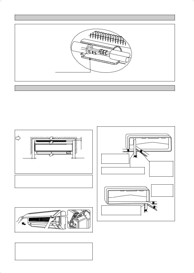
DIAGRAMME D’INSTALLATION
BANDE DE LIÈGE TOTALEMENT ISOLÉE
ISOLATION DES TUYAUTERIES DʼEAU GLACÉE
INSTALLATION DE L’UNITÉ INTÉRIEURE
Installer l’unité intérieure de traitement d’air de façon à ce qu’il n’y ait aucun obstacle sur la circulation de l’air (risque de recyclage de l’air refroidi au refoulement de l’unité et l’air à l’entrée). Veuillez respecter l’écartement d’installation illustré sur le diagramme. Ne pas exposer l’unité intérieure à l’influence directe de l’éclairage. L’emplacement de l’unité, doit permettre une évacuation aisée des condensats, et permettre une evacuation aisee des condensats, et doit être suffisamment loin des portes.
Flux d’air |
|
mini 30 (Espace pour performance) |
|
(Intérieur) |
|
||
|
|
||
mini 50 |
Espace nécessaire |
mini 50 |
|
(Espace pour |
(Espace pour |
||
|
|||
entretien) |
|
entretien) |
|
|
Toutes les dimensions sont données en mm |
||
! AVERTISSEMENT
Ne pas installer l’appareil à une altitude de plus de 2000m.
Purge d’air
Pour éviter d’endommager la pompe, la bobine du ventilateur ne doit pas être alimentée et toutes les conduites d’eau doivent avoir été purgées de leur air.
L’évent situé à l’intérieur de l’enveloppe. Retirez l’enveloppe et raccordez le flexible à l’évent pendant la purge.
La tuyauterie d’eau peut être dirigée vers l’unité de plusieurs manières (sur la gauche ou la droite, depuis l’arrière de l’appareil), par le biais des orifices défonçables situés sur l’enveloppe de l’appareil (voir figure). Cintrer les tuyaux avec précaution afin de les aligner avec les orifices. Pour les sorties latérale et inférieure, maintenir le bas de la tuyauterie et la positionner dans la bonne direction (voir figure). Le flexible d'évacuation des condensats peut être fixé aux tuyaux.
Tuyauterie sur le côté droit, à l’arrière droite ou en bas à droite
Tuyautage du côté droit
Retirez le couvercle du |
|
|
port du tube ici pour le |
Tuyautage du |
|
tuyautage du côté droit |
||
côté inférieur |
||
|
||
|
droit |
Retirez le couvercle du port du tube ici pour le tuyautage du côté inférieur droit
Tuyautage du côté arrière droit
Attachez ensemble le tube de réfrigérant avec le tuyau de vidange avec du ruban isolant.
Tuyauterie sur le côté gauche, à l’arrière gauche ou en bas à gauche
|
Retirez le couvercle |
|
|
du port du tube ici |
|
|
pour le tuyautage |
|
|
du côté gauche |
|
|
Tuyautage du |
|
|
côté gauche |
|
Retirez le couvercle du port du tube |
Tuyautage du |
|
ici pour le tuyautage du côté arrière |
||
côté arrière |
||
gauche |
||
gauche |
||
|
||
Tuyautage du côté inférieur gauche |
||
! AVERTISSEMENT
Assurez-vous qu’aucune goutte d’eau ne tombe dans le boîtier de commande pendant la purge.
3-4

Montage De La Platine Support
S’assurrer que le mur de support soit suffisamment résistant, pour supporter le poids de l’unité et éviter toutes vibrations. Selon la composition du mur, utiliser des vis chevilles appropriées pour la fixation de la platine support.
Utilisez l'indicateur de niveau pour le montage horizontal, et fixez-le avec 5 vis adaptées pour FWT02/03/04 et 7 vis adaptées pour FWT05/06.
Dans le cas de sortie arrière des tuyauteries, percer le trou 65mm pour les canalisations à l’aide d’une scie cloche. Le trou aura une légère pente vers l’unité extérieure (voir la figure).
FWT02/03/04 |
Plaque de montage |
|
Vis de fixation de la plaque de montage
FWT05/06
 Plaque de montage
Vis de fixation de la  plaque de montage
Point De Retenue Et Dimensions Recommandés Pour La Platine De Montage
FWT02/03/04
Points de fixation de la plaque |
Utilisez un mètre à ruban comme |
||||
de montage recommandés |
|
indiqué, placez l’extrémité du |
|
||
(5 points en tout) |
|
mètre à ruban sur |
|
|
|
|
166 |
|
|
184 |
|
42,2 |
|
|
|
42,2 |
|
288 |
|
|
|
|
Trou percé |
|
|
|
|
|
|
|
|
|
|
|
dans le mur |
|
|
|
|
|
à Ø 65mm |
45,9 |
|
|
181,7 |
45,9 |
Position |
54,5 |
153,8 |
|
55,5 |
||
|
263 |
51,9 |
800 |
|
du tuyau |
|
Entrée dʼeau |
|
Sortie dʼeau |
|
d’évacuation |
|
|
|
|
||
Toutes les dimensions sont données en mm
FWT05/06
 Points de fixation de la plaque de montage recommandés (7 points en tout)
190 |
173 |
61 |
61 |
310 |
|
|
|
|
Trou percé |
|
|
|
|
|
dans le mur |
40 |
|
|
|
|
à Ø 65mm |
|
|
|
|
40 |
|
45 91 |
Entrée dʼeau |
Sortie dʼeau |
219 |
48 |
Position |
|
580 |
45 |
|
|
du tuyau |
|
|
1065 |
|
|
d’évacuation |
|
|
|
|
|
Toutes les dimensions sont données en mm
Trou Avec Perceuse En Cône
Intérieur 

Tube noyé dans le mur (À se procurer sur place)
Couvercle de trou de mur (À se procurer sur place)
Extérieur
Calfatage
Ø 65
Tube noyé dans le mur (À se procurer sur place)
Mise En Place De L’unite De La Platine Support
Positionner dans un premier temps l’unité intérieure sur la languette d’accrochage supérieure de support. Pour vous assurer que les crochets sont correctement installés sur la plaque d’installation, essayez de les faire légèrement bouger de gauche à droite.
Comment Fixer L’unité Interne
Accrochez les griffes de la structure inférieure à la plaque de montage.
Comment Démonter L’unité Interne
Soulevez la zone marquée d’un repère (au bas de la grille avant) pour libérer les griffes.
Plaque de montage
Attache
Grille frontale |
Châssis inférieur |
Repère |
|
|
(à l’arrière) |
Accrochez les crochets de l’appareil intérieur ici.
|
Plaque de |
|
Quand vous dénudez |
montage |
|
en avance les fils |
|
|
d’interconnexion, |
Fils |
|
recouvrez les |
||
d’interconnexion |
||
extrémités des fils |
||
|
||
avec du ruban isolant. |
Guide de fil |
|
|
Évacuation Des Condensats
Le tube d’évacuation des condensats de l’unité devra être, dans la mesure du possible, dirigé vers la sortie arriere des tuyauteries a travers le mur de support. Evitez les situations susceptibles de causer une fuite d’eau.
Drainage De L’eau
|
|
Rétention |
|
|
|
de l’eau |
Evacuation |
|
|
|
|
Fuite |
Fuite |
Fuite |
d’eau de |
condensation |
|||
d’eau |
d’eau |
d’eau |
plongé dans |
|
|
|
l’eau |
Drainage
Correct |
Mauvais |
Mauvais |
Mauvais |
Français
3-5

Raccordement des tuyauteries
L’unité intérieure est pourvue d’un raccordement fileté pour l’entrée et la sortie d’eau. Un évent de purge d’air est fixé au collecteur de sortie. Une 3 voies est nécessaire pour l’arrêt du cycle ou la dérivation de l’eau glacée.
Des tuyaux en acier noir, en polyuréthanne, en PVC et en cuivre son recommandés pour l’installation chez le client.
Tous les types de tuyauterie et de raccordements doivent être isolés au moyen de polyuréthanne (de type ARMAFLEX ou équivalent) pour éviter la condensation.
N’utilisez pas de tuyaux et raccords contaminés ou endommagés pour l’installation.
Certains composants de raccordement principaux sont nécessaires pour optimiser le système et faciliter le service : robinet-vanne, vanne
d’équilibrage, 2 voies ou 3 voies, filtre, crépine. |
|
|
|
|
||
|
Robinet- |
|
Robinet- |
|
Robinet- |
|
|
vanne |
Vanne 3 voies |
vanne |
Vanne 2 voies |
||
|
vanne |
|||||
|
|
|
|
|
||
Refroidisseur |
Robinet- |
FCU |
Robinet- |
FCU |
FCU |
|
vanne |
vanne |
|||||
|
|
|||||
|
|
|
|
|
Robinet- |
|
|
|
|
|
|
vanne |
|
|
|
Bon Contrôle |
|
Mauvais Contrôle |
Très Mauvais Contrôle |
|
RACCORDEMENT ÉLECTRIQUE
IMPORTANT : * Ces valeurs sont données à titre indicatif seulement; elles doivent être vérifiées et ajustées en fonction des normes et de la réglementations en vigueur. Elles dépendent aussi du type d’installation et des conducteurs utilisés.
**Le voltage adéquat doit être vérifié avec les données de l’étiquette surl’appareil.
Il doit y avoir une déconnexion de tour les pôles de l’alimentation secteur avec une séparation des contacts d’au moins 3mm.
Modèle |
|
FWT02/03/04/05/06 |
|
|
|
Tension d’alimentation** |
|
220V – 240V/1Ph/50Hz + ! |
|
|
|
Section du câble d’alim* |
mm2 |
1,5 |
Nombre de conducteurs |
|
3 |
|
|
|
Fusible temporisé recommandé |
A |
2 |
|
|
|
•Tous les fils doivent être fermement connectés.
•Aucun fils ne doivent toucher les tubes frigorifiques, le compresseur ou une autre partie mobile du moteur de ventilateur.
•Les fils se reliants à l’unité d’intérieur doivent être maintenus sur les brides de fil comme représenté sur la figure.
•Le cordon d’alimentation doit être équivalent à la norme H07RN-F qui constitue la condition minimale, et doit être utilisé dans un tube de protection.
Pince A Fil
Cable De
Connection
Cordon Electrique
FWT02/03/04/05/06
FCU3 |
|
FCU2 |
|
|
FCU1 |
VALVE N1 |
N L |
VALVE N1 |
N L |
VALVE N1 |
N L |
3wv |
|
3wv |
|
3wv |
N |
|
|
|
|
|
T |
|
|
|
|
|
S |
|
|
|
|
|
R |
|
x1 |
|
|
x2 |
x3 |
3WV Vanne 3 voies
x1x2x3 Relais (220-240V, 10A)
Refroidisseur
3-6
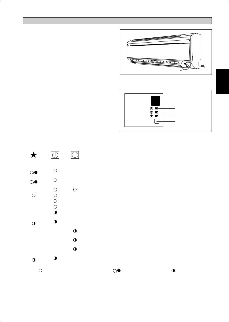
L’INDICATEUR S’ALLUME
IR Récepteur De Signal
Lorsqu’un signal de fonctionnement est transmis par une télécommande à infrarouges, le récepteur de signal de l’unité intérieure répond comme ci-dessous pour confirmer l’acceptation de la transmission du signal.
MARCHE vers ARRÊT |
1 bip long |
ARRÊT vers MARCHE |
2 bips courts |
Pompe bas/Force de |
|
refroidissement activée |
|
Autres |
1 bips courts |
|
|
Module Refroidisseur/Module Pompe À Chaleur
Le tableau ci-dessous reprend en détail la visualisation par led, des conditions normales de fonctionnement, et conditions de défaut du climatiseur.
Les voyants de signalisation de LED sont situés en bas à droite du climatiseur.
IR Récepteur De Signal |
|
L’indicateur LED S’allume Pour L’Unité De |
Français |
Refroidissement/Module Pompe À Chaleur |
|
|
 IR Récepteur De Signal
Refroidissement/ Chauffage
Minuterie
Mise en sommeil
ON/OFF |
Interrupteur de |
|
MARCHE/ARRÊT |
L’indicateur LED S’allume: Conditions De Fonctionnement Normales Et Par Défaut Pour L’Unité De Refroidissement/Module Pompe À Chaleur
|
|
|
|
|
|
|
Opération/Indication de panne |
Action |
Code de |
|
|
|
|
|
|
|
|||
|
|
|
|
|
|
|
|||
|
|
|
REFROIDISSEZ/ |
|
|
|
|
|
l’erreur |
|
|
|
CHALEUR |
|
|
|
|
|
|
|
|
|
(VERT/ROUGE) |
|
|
|
|
|
|
|
|
|
|
|
|
|
|
|
|
|
|
|
Vert |
|
|
|
Mode refroidissement |
- |
- |
|
|
|
|
|
|
|
|
|
|
|
|
|
|
|
|
|
|
|
|
|
|
|
Rouge |
|
|
|
Mode chauffage |
- |
- |
|
|
|
|
|
|
|
|
|
|
|
|
|
|
|
|
|
|
|
|
|
|
|
|
|
|
|
Minuterie en marche |
- |
- |
|
|
|
|
|
|
|
|
|
|
|
|
|
|
|
|
|
Mode de sommeil |
- |
- |
|
|
|
|
|
|
|
|
|
|
|
|
|
|
|
|
|
Mode ventilateur activé |
- |
- |
|
|
|
|
|
|
|
|
|
|
|
|
|
|
|
|
|
Mode sec activé |
- |
- |
|
|
|
|
|
|
|
|
|
|
|
|
|
|
|
|
|
Défaut de la sonde de reprise d’air lachement/court |
Contacter votre |
L’indicateur E1 |
|
|
|
1 fois |
|
|
|
revendeur |
clignote |
|
|
|
|
|
|
|
|
|||
|
|
|
|
|
|
|
|
|
|
|
|
|
|
|
|
|
Capteur à bobine intérieur ouvert/court |
Contacter votre |
L’indicateur E2 |
|
|
|
2 fois |
|
|
|
revendeur |
clignote |
|
|
|
|
|
|
|
|
|||
|
|
|
|
|
|
|
|
|
|
|
|
|
|
|
|
|
Faible température du tuyau d’eau |
- |
L’indicateur E4 |
|
|
|
|
|
3 fois |
clignote |
|||
|
|
|
|
|
|
|
|||
|
|
|
|
|
|
|
|
|
|
|
|
|
|
|
|
|
Mauvaise température du tuyau d’eau |
- |
L’indicateur E5 |
|
|
|
|
|
1 fois |
clignote |
|||
|
|
|
|
|
|
|
|||
|
|
|
|
|
|
|
|
|
|
|
|
|
|
|
|
|
Erreur matérielle |
Contacter votre |
L’indicateur E8 |
|
|
|
|
|
6 fois |
(broche de commutation discrète faible) |
revendeur |
clignote |
|
|
|
|
|
|
|
|
|
|
|
|
|
|
|
|
|
|
Aucune réaction du ventilateur intérieur |
Contacter votre |
L’indicateur E9 |
|
|
|
4 fois |
|
|
|
revendeur |
clignote |
|
|
|
|
|
|
|
|
|||
|
|
|
|
|
|
|
|
|
|
|
|
SUR |
Led Allumée Ou Éteinte |
Led clignotante |
|||||
3-7
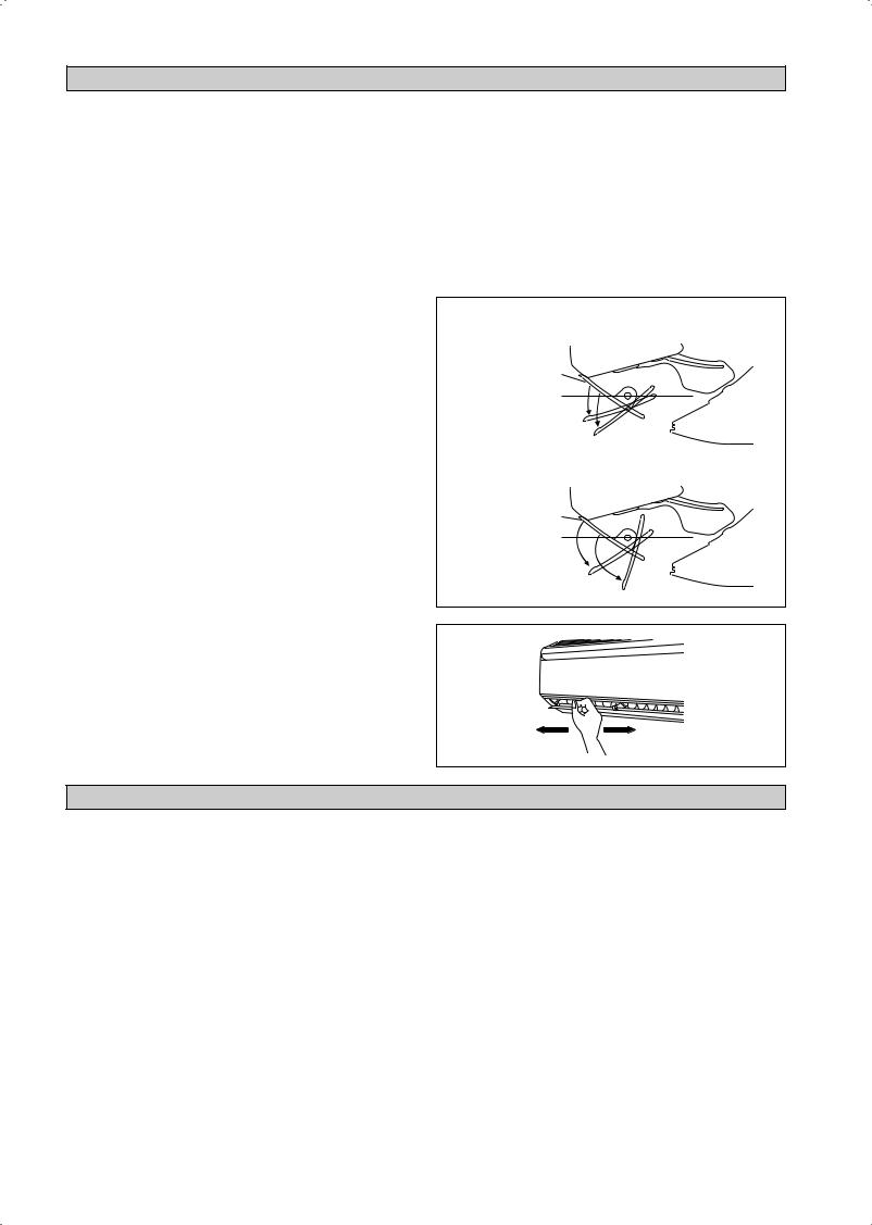
OPERATION DU CLIMATISEUR
Déshumidification
•Lorsque le taux d’humidité de l’air est élevé, le climatiseur peut fonctionner en mode de déshumidification. Appuyer sur la touche <MODE> et sélectionner <DRY>.
•Au cas où la température de la pièce est de 2°C/3,6°F supérieure à la température affichée, le climatiseur - avant de passer en mode de déshumidification - fonctionnera en mode de refroidissement jusqu’à ce que la température soit retombée dans la limite des 2°C/3,6°F de différence par rapport à la température affichée.
•Si la température de la pièce se trouve dans la limite des 2°C/3,6°F de différence par rapport à la température affichée, l’appareil fonctionnera directement en mode de déshumidification.
•En mode de déshumidification, l’appareil fonctionne à FAIBLE vitesse de ventilatio.
Chauffage (concerne seulement la pompe à chaleur)
•Lorsque l’appareil est réglé en mode courant d’air froid ou après un cycle de dégivrage, le ventilateur intérieur se mettra à tourner seulement une fois que le serpentin aura atteint la température souhaitée.
•Pour le réglage en mode ventilateur, le ventilateur intérieur fonctionnera en continu une fois l’unité en position ON.
•Lorsque la température souhaitée est atteinte, le ventilateur intérieur tournera jusqu’à ce que le serpentin ne puisse plus fournir de chaleur supplémentaire.
Contrôle Du Débit D’air
•Pour obtenir une meilleure circulation d’air, vous pouvez ajuster la grille de refoulement d’air froid vers la gauche ou vers la droite à la main.
•Pendant le fonctionnement en mode froid ou déshumidification, il n’y a pas un refoulement d’air froid pendant un long moment vers le bas. Car il pourrait se produire de la condensation sur les volets d’air suivi d un écoulement d’eau.
Vitesse De Ventilation Et Capacité Nominale De
Refroidissement
•La capacité nominale de refroidissement peut être atteinte en vitesse de ventilation ÉLEVÉE.
•La capacité de refroidissement est plus faible lorsque l’appareil fonctionne en vitesse de ventilation MOYENNE ou FAIBLE.
Remarques Sur les Angles Des Volets Et Déflecteurs
•Lorsque vous sélectionnez la touche « OSCILLATION », la plage d’oscillation des volets dépend du mode defonctionnement. (Voir la figure.)
ATTENTION
•Réglez toujours l’angle du volet avec la télécommande. Si vous tentez de forcer le volet à la main alors qu’il pivote, le mécanisme pourrait se casser.
•Faites attention lorsque vous réglez les déflecteurs. Un ventilateur tourne à grande vitesse à l’intérieur de la sortie d’air.
En mode REFROIDISSEMENT, SECHAGE, et VENTILATEUR
Lors de l’arrêt du fonctionnement
Limite supérieure 55°
Limite inférieure 75°
En mode CHAUFFAGE
Lors de l’arrêt du fonctionnement
Limite supérieure 70˚
Limite inférieure 110˚
PLAGE D’EXPLOITATION
Limites de fonctionnement:
Porteur thermique : Eau
Température de l’eau : 4-10°C Refroidissement, 35-50°C Chauffage Pression d’eau maximale : 16 bars
Température de l’air : (comme ci-dessous)
Refroidissement Mode
Température |
Ts °C/°F |
Th °C/°F |
|
|
|
|
|
Température |
19,0 / 66,2 |
14,0 / 57,2 |
|
intérieure minimum |
|||
|
|
||
Température |
32,0 / 89,6 |
23,0 / 73,4 |
|
intérieure maximum |
|||
|
|
Mode chauffage
Température |
Ts °C/°F |
Th °C/°F |
|
|
|
|
|
Température |
15,0 / 59,0 |
- |
|
intérieure minimum |
|||
|
|
||
Température |
27,0 / 80,6 |
- |
|
intérieure maximum |
|||
|
|
Ts: Température au thermomètre sec. |
Th: Température au thermomètre mouillé. |
3-8
 Loading...