


Daikin FWE02C5TV1B, FWE03C5TV1B, FWE04C5TV1B, FWE06C5TV1B, FWE07C5TV1B Installation manuals
...INSTALLATION and
OPERATIONAL MANUAL
Installation and operation manual
Ceiling Concealed Fan Coil Units
Tanıtma ve Kullanma Kılavuzu Montage und Bedienungsanleitung Manuel d’installation et d’exploitation Installatieen Gebruikshandleiding
Manual de Instalación y Funcionamiento Manuale d’installazione e d’uso Εγχειρίδο Εγκατάσταση και Λειτουργία Manual de instalação e utilização
• • • •• • •
• • • •• • •
Telepítési és Kezelési Útmutató
Álmennyezeti Típusu Ventilátoros Konvektor Egységek
English
Türkçe
Deutsch
Français
Nederlandse
Español
Italiano
ελληνικά
Português
P••• •
Magyar
Models :
FWE02C5TV1B FWE02C5FV1B FWE03C5TV1B FWE03C5FV1B FWE04C5TV1B FWE04C5FV1B FWE06C5TV1B FWE06C5FV1B FWE07C5TV1B FWE07C5FV1B FWE08C5TV1B FWE08C5FV1B
FWE10C5TV1B FWE10C5FV1B
3PW90198-1C
Dear Customer,
We thank you for choosing DAIKIN products.
This installation guide contains explanations about the safety and standard operating.
Before installation and maintenance of Fan coil units , please read safety and warnings and keep guide carefully for installation and maintenance process.
Please give importance to the general warnings.
This appliance is intended to be used by expert or trained users in shops, in light industry and on farms, or for commercial use by lay persons.
This untreated household waste electrical and
!electronic products should not be confused. Do not disassemble the system on your own, Removal system, coolant, oil and other parts should be performed by
legislation. The units should be operated in special facilities for reuse and recycling. Please help in preventing potential negative consequences for human and the environment health by providing the product is disposed of correctly. For more information please contact the autorized person or a person who performed the installation
Manufacturer Firm:
DAIKIN EUROPE N.V.
Zandvoordestraat 300, B-8400 Oostende, Belgium
Tel: (+32)59/55 81 11
Fax: (+32)59/55 88 99
Production Plant :
Daikin Isıtma ve Soğutma Sistemleri San. Tic. A.ẞ. 2. OSB 54300 Hendek/SAKARYA,TURKEY
Tel |
: +90264 |
616 27 00 |
Fax |
: +90264 |
654 58 45-46 |
Made in Turkey
Contents |
|
1. General Information |
5 |
2. Dimensions |
10 |
3. Installation |
11 |
4. Maintenance |
16 |
Safety Precautions
Before installing the fan coil unit, please read the following safety precautions carefully.
WARNING
Use experienced personnel during the installation and commissioning. Electricity and water connections must be done by a
•During installation and setup of the product, please note the type and declaration labels and coding.
•Appropriate all connections accordance with color coding system of cable and international coding procedures .
•If you are not sure how to operate the unit, contact your installer. The appliance is not intended for use by persons, including children, with reduced physical, sensory or mental capabilities, or lack of experience and knowledge, unless they have been given supervision or instruction concerning use of the appliance by a person responsible for their safety. Children should be supervised to ensure that they do not play with the appliance.
•Provide the unit being accordance with operating voltage value and power cables.
•Otherwise, you can cause damage to the unit.
•A main switch or other means for disconnection, having a contact separation in all poles providing full disconnection under overvoltage
•When the electrical connections are done , energy should not be on the main power supply cable and main switch should be closed.
•During the electrical connections, make sure that the cables are well-
• After all controllers are done , commission the unit.
•Do not attempt to repair the unit by using operational and installation manual. There are no threads of repair of unit in this guide.
•Please be careful to avoid tight electrical connections not to damage on the electrical connections.
Warnings associated with the transportation appliance:
•Protect your unit from impact and excessive vibration.
•Take the necessary measures to avoid the unit under water.
•Carry the unit by being careful to the universal transport signs and warnings that are located on the package.
ENGLISH
 1. General Information
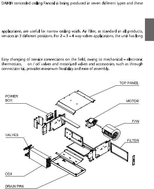
types has two models, as 2- pipe, 4-pipe. (Total 14 variety.) Applications are suitable for duct and duct-free. Requiring to the standard production 0 – 30 Pa air pressure loss, the production can be made according to the loss of air pressure 60 – 80 Pa.
Quiet operation, compact size, owing to low weight, especially through ceiling
drain pan that manufactured by pan plastering method and isolated with exclusive insulation materials. As a standard 4 – speed stepped and mono phase electric motor is used . (Figure-1)
Figure-1
<![endif]>ENGLISH
5
<![endif]>ENGLISH
|
TYPE 2 PIPE |
|
FWE02C5TV1B |
FWE03C5TV1B |
FWE04C5TV1B |
FWE06C5TV1B |
FWE07C5TV1B |
FWE08C5TV1B |
FWE10C5TV1B |
||
|
|
|
|
|
|
|
|
|
|
|
|
|
Power Supply |
|
|
|
220-240V / 1 ~ / 50 Hz |
|
|
||||
|
|
|
|
|
|
|
|
|
|
|
|
|
Super High Fan Speed |
|
430 |
638 |
910 |
1195 |
1559 |
1753 |
2177 |
||
|
|
|
|
|
|
|
|
|
|
|
|
Nominal Air |
High Fan Speed |
|
311 |
518 |
619 |
926 |
1188 |
1413 |
1735 |
||
|
|
|
|
|
|
|
|
|
|
||
Flow |
Middle Fan Speed |
|
238 |
385 |
413 |
630 |
851 |
1016 |
1202 |
||
|
|
||||||||||
|
|
|
|
|
|
|
|
|
|
|
|
|
Low Fan Speed |
|
150 |
256 |
284 |
426 |
569 |
688 |
808 |
||
|
|
|
|
|
|
|
|
|
|
|
|
|
|
Total |
|
2,17 |
3,22 |
4,34 |
6,06 |
6,83 |
7,84 |
9,96 |
|
|
Cooling |
|
|
|
|
|
|
|
|
|
|
Capacity |
Sensible |
kW |
1,61 |
2,44 |
3,27 |
4,55 |
4,83 |
6,02 |
7,58 |
||
|
|||||||||||
|
|
|
|
|
|
|
|
|
|
|
|
|
Heating |
|
2,79 |
4,28 |
5,61 |
7,66 |
9,26 |
10,50 |
13,00 |
||
|
|
|
|
|
|
|
|
|
|
||
Water Flow |
Cooling |
|
0,10 |
0,15 |
0,21 |
0,29 |
0,33 |
0,38 |
0,48 |
||
|
|
|
|
|
|
|
|
|
|
||
Rate |
Heating |
|
0,07 |
0,10 |
0,14 |
0,19 |
0,23 |
0,26 |
0,33 |
||
|
|
||||||||||
|
|
|
|
|
|
|
|
|
|
||
Water |
Cooling |
|
15,1 |
11,7 |
23,9 |
46,4 |
14,8 |
19,3 |
32,9 |
||
Pressure |
|
|
kPa |
|
|
|
|
|
|
|
|
Heating |
6,1 |
4,9 |
9,7 |
17,9 |
6,6 |
8,4 |
13,7 |
||||
Drop |
|
||||||||||
|
|
|
|
|
|
|
|
|
|
|
|
|
PI (0 Pa) |
kW |
0,046 |
0,069 |
0,083 |
0,119 |
0,163 |
0,181 |
0,230 |
||
|
|
|
|
|
|
|
|
|
|
||
|
Super High Fan Speed |
|
51 |
61 |
58 |
62 |
62 |
64 |
65 |
||
|
|
|
|
|
|
|
|
|
|
||
Sound |
High Fan Speed |
|
49 |
56 |
48 |
55 |
57 |
58 |
60 |
||
Power |
|
|
dB(A) |
|
|
|
|
|
|
|
|
|
|
|
|
|
|
|
|
|
|||
Level |
Middle Fan Speed |
|
37 |
49 |
38 |
46 |
47 |
50 |
50 |
||
|
|
|
|
|
|
|
|
|
|
||
|
Low Fan Speed |
|
31 |
38 |
32 |
39 |
38 |
41 |
40 |
||
|
|
|
|
|
|
|
|
|
|
||
|
Super High Fan Speed |
|
41 |
51 |
48 |
52 |
52 |
54 |
55 |
||
Sound |
|
|
|
|
|
|
|
|
|
||
High Fan Speed |
|
39 |
46 |
38 |
45 |
47 |
48 |
49 |
|||
Pressure |
|
|
dB(A) |
|
|
|
|
|
|
|
|
|
|
26 |
39 |
28 |
36 |
37 |
40 |
39 |
|||
Level |
Middle Fan Speed |
|
|||||||||
|
|
|
|
|
|
|
|
|
|
||
|
Low Fan Speed |
|
21 |
28 |
22 |
29 |
27 |
31 |
29 |
||
|
|
|
|
|
|
|
|
|
|
||
|
Width |
|
590 |
590 |
590 |
590 |
590 |
590 |
590 |
||
Unit |
|
|
|
|
|
|
|
|
|
|
|
Height |
mm |
253 |
253 |
253 |
253 |
253 |
253 |
253 |
|||
Dimensions |
|||||||||||
|
|
|
|
|
|
|
|
|
|
||
|
Depth |
|
705 |
875 |
1005 |
1205 |
1455 |
1555 |
1815 |
||
|
|
|
|
|
|
|
|
|
|
||
|
Width |
|
605 |
605 |
605 |
605 |
605 |
605 |
605 |
||
Packaged |
|
|
|
|
|
|
|
|
|
|
|
Height |
mm |
260 |
260 |
260 |
260 |
260 |
260 |
260 |
|||
Dimensions |
|||||||||||
|
|
|
|
|
|
|
|
|
|
||
|
Depth |
|
720 |
890 |
1020 |
1220 |
1470 |
1570 |
1830 |
||
|
|
|
|
|
|
|
|
|
|
||
Weight |
Net |
Kg |
18 |
21 |
25 |
30 |
39 |
42 |
47 |
||
|
|
|
|
|
|
|
|
|
|||
Gross |
20 |
23 |
27 |
33 |
42 |
45 |
51 |
||||
|
|
||||||||||
|
|
|
|
|
|
|
|
|
|
|
|
For cooling, Air temp. 27/19 °C DB/WB and 7/12 °C water inlet/outlet temp.
For heating, Air temp. 20/15 °C DB/WB and 50/40 °C water inlet/outlet temp.
Capacity values are in super high speed mode.
Sound Pressure Levels measured 1m distance from air outlet.
All declared values are for ESP "0 Pa"
6
|
TYPE 4 PIPE |
|
FWE02C5FV1B |
FWE03C5FV1B |
FWE04C5FV1B |
FWE06C5FV1B |
FWE07C5FV1B |
FWE08C5FV1B |
FWE10C5FV1B |
||
|
|
|
|
|
|
|
|
|
|
|
|
|
Power Supply |
|
|
|
220-240V / 1 ~ / 50 Hz |
|
|
||||
|
|
|
|
|
|
|
|
|
|
|
|
|
Super High Fan Speed |
|
416 |
626 |
835 |
1193 |
1548 |
1742 |
2166 |
||
|
|
|
|
|
|
|
|
|
|
|
|
Nominal Air |
High Fan Speed |
|
302 |
501 |
571 |
905 |
1173 |
1386 |
1729 |
||
|
|
|
|
|
|
|
|
|
|
||
Flow |
Middle Fan Speed |
|
232 |
371 |
377 |
618 |
846 |
1001 |
1199 |
||
|
|
||||||||||
|
|
|
|
|
|
|
|
|
|
|
|
|
Low Fan Speed |
|
142 |
256 |
257 |
414 |
569 |
684 |
804 |
||
|
|
|
|
|
|
|
|
|
|
|
|
|
Cooling |
Total |
|
2,100 |
3,160 |
3,980 |
6,050 |
6,780 |
7,790 |
9,910 |
|
|
|
|
|
|
|
|
|
|
|
||
Capacity |
Sensible |
kW |
1,550 |
2,370 |
3,190 |
4,490 |
5,160 |
5,910 |
7,450 |
||
|
|||||||||||
|
|
|
|
|
|
|
|
|
|
|
|
|
Heating |
|
2,300 |
3,530 |
4,560 |
6,170 |
7,600 |
8,520 |
10,400 |
||
|
|
|
|
|
|
|
|
|
|
||
Water Flow |
Cooling |
l/s |
0,10 |
0,15 |
0,20 |
0,29 |
0,33 |
0,37 |
0,48 |
||
|
|
|
|
|
|
|
|
|
|||
Rate |
Heating |
0,03 |
0,05 |
0,06 |
0,09 |
0,12 |
0,13 |
0,16 |
|||
|
|||||||||||
|
|
||||||||||
|
|
|
|
|
|
|
|
|
|
|
|
Water pressure drop - Cooling coil |
kPa |
14,5 |
11,4 |
21,6 |
46,3 |
14,6 |
19,1 |
32,7 |
|||
|
|
|
|
|
|
|
|
|
|||
Water pressure drop – Additional |
kPa |
3,6 |
8,8 |
15,6 |
31,8 |
58,6 |
74,6 |
123,0 |
|||
(Heating) coil |
|||||||||||
|
|
|
|
|
|
|
|
||||
|
|
|
|
|
|
|
|
|
|
||
|
PI (0Pa) |
kW |
0,046 |
0,069 |
0,083 |
0,119 |
0,163 |
0,181 |
0,230 |
||
|
|
|
|
|
|
|
|
|
|
||
|
Super High Fan Speed |
|
51 |
61 |
58 |
62 |
62 |
64 |
65 |
||
|
|
|
|
|
|
|
|
|
|
||
Sound Power |
High Fan Speed |
|
49 |
56 |
48 |
55 |
57 |
58 |
60 |
||
|
|
dB(A) |
|
|
|
|
|
|
|
||
Level |
Middle Fan Speed |
37 |
49 |
38 |
46 |
47 |
50 |
50 |
|||
|
|||||||||||
|
|
||||||||||
|
|
|
|
|
|
|
|
|
|
||
|
Low Fan Speed |
|
31 |
38 |
32 |
39 |
38 |
41 |
40 |
||
|
|
|
|
|
|
|
|
|
|
||
|
Super High Fan Speed |
|
41 |
51 |
48 |
52 |
52 |
54 |
55 |
||
Sound |
|
|
|
|
|
|
|
|
|
||
High Fan Speed |
|
39 |
46 |
38 |
45 |
47 |
48 |
49 |
|||
Pressure |
|
|
dB(A) |
|
|
|
|
|
|
|
|
Middle Fan Speed |
26 |
39 |
28 |
36 |
37 |
40 |
39 |
||||
Level |
|
||||||||||
|
|
|
|
|
|
|
|
|
|
||
|
Low Fan Speed |
|
21 |
28 |
22 |
29 |
27 |
31 |
29 |
||
|
|
|
|
|
|
|
|
|
|
||
|
Width |
|
590 |
590 |
590 |
590 |
590 |
590 |
590 |
||
Unit |
|
|
|
|
|
|
|
|
|
|
|
Height |
mm |
253 |
253 |
253 |
253 |
253 |
253 |
253 |
|||
Dimensions |
|||||||||||
|
|
|
|
|
|
|
|
|
|
||
|
Depth |
|
705 |
875 |
1005 |
1205 |
1455 |
1555 |
1815 |
||
|
|
|
|
|
|
|
|
|
|
||
|
Width |
|
605 |
605 |
605 |
605 |
605 |
605 |
605 |
||
Packaged |
|
|
|
|
|
|
|
|
|
|
|
Height |
mm |
260 |
260 |
260 |
260 |
260 |
260 |
260 |
|||
Dimensions |
|||||||||||
|
|
|
|
|
|
|
|
|
|
||
|
Depth |
|
720 |
890 |
1020 |
1220 |
1470 |
1570 |
1830 |
||
|
|
|
|
|
|
|
|
|
|
||
Weight |
Net |
Kg |
19 |
22 |
26 |
31 |
41 |
43 |
50 |
||
|
|
|
|
|
|
|
|
|
|||
Gross |
21 |
24 |
28 |
34 |
45 |
47 |
54 |
||||
|
|
||||||||||
|
|
|
|
|
|
|
|
|
|
|
|
<![endif]>ENGLISH
For cooling, Air temp. 27/19 °C DB/WB and 7/12 °C water inlet/outlet temp. For heating, Air temp. 20/15 °C DB/WB and 50/40 °C water inlet/outlet temp. Capacity values are in super high speed values
Sound Pressure Levels measured 1m distance from air outlet
All declared values are for ESP "0 Pa"
7

 Component Technical Specifications
<![endif]>ENGLISH
|
MODEL |
|
FWE02C5TV1 |
FWE03C5TV1B |
|
FWE04C5TV1B |
|
FWE06C5TV1B |
|
FWE07C5TV1B |
FWE08C5TV1B |
FWE10C5TV1B |
|
|
|
|
|
|
|
|
|
|
|
|
|
||
|
Type |
|
|
|
|
Centrifugal ( Blade: Forward - curve ) |
|
|
|||||
|
|
|
|
|
|
|
|
|
|
|
|
||
|
Quantity |
|
1 |
1 |
|
2 |
|
2 |
|
3 |
3 |
4 |
|
|
|
|
|
|
|
|
|
|
|
|
|
|
|
| <![if ! IE]> <![endif]>Fan |
Material |
|
|
|
|
|
|
Galvanized Steel |
|
|
|
||
|
|
|
|
|
|
|
|
|
|
|
|
|
|
Drive |
|
|
|
|
|
|
Direct Drive |
|
|
|
|||
|
|
|
|
|
|
|
|
|
|
||||
|
|
|
|
|
|
|
|
|
|
|
|
|
|
|
Diameter (mm) |
|
|
|
|
|
235,5 |
|
|
|
|
||
|
|
|
|
|
|
|
|
|
|
|
|
|
|
|
Length (mm) |
|
|
|
|
|
266 |
|
|
|
|
||
|
|
|
|
|
|
|
|
|
|
||||
|
|
|
|
|
|
|
|
|
|
||||
|
Type |
|
|
|
|
Split - Capacitor Motor With Ball Bearing |
|
|
|||||
|
|
|
|
|
|
|
|
|
|
|
|
||
| <![if ! IE]> <![endif]>Motor |
Number of motors |
|
|
1 |
|
|
|
|
2 |
|
|||
|
|
|
|
|
|
|
|
|
|
|
|
|
|
Power supply |
|
|
|
|
|
220 - 240 V / 1 / 50 Hz |
|
|
|||||
|
|
|
|
|
|
|
|
||||||
|
|
|
|
|
|
|
|
|
|
|
|
||
|
IP / Insulation Class |
|
|
|
|
|
IP 20 / Class B |
|
|
|
|||
|
|
|
|
|
|
|
|
|
|
|
|
|
|
|
Poles |
|
|
|
|
|
4 |
|
|
|
|
||
|
|
|
|
|
|
|
|
|
|
||||
|
Type |
|
|
|
|
Corrugated Fin, Sine Wave Rippled Edge |
|
|
|||||
|
|
|
|
|
|
|
|
|
|
||||
|
Testing Pressure |
|
|
|
|
Pressure Test: 3,0 MPa For 1 Minute |
|
|
|||||
|
|
|
|
|
|
|
|
|
|
|
|
|
|
|
|
|
Material |
|
|
|
|
|
Copper |
|
|
|
|
|
|
|
|
|
|
|
|
|
|
|
|
|
|
|
Tube |
|
Diameter (mm) |
|
|
|
|
9,52 |
|
|
|
|
|
| <![if ! IE]> <![endif]>Coil |
|
|
|
|
|
|
|
|
|
|
|
|
|
|
|
Thickness (mm) |
|
|
|
|
0,35 |
|
|
|
|
||
|
|
|
|
|
|
|
|
|
|
|
|||
|
|
|
Material |
|
|
|
|
Hydrophilic Aluminum |
|
|
|||
|
|
|
|
|
|
|
|
|
|
|
|
|
|
|
Fin |
|
Thickness (mm) |
|
|
|
|
0,105 |
|
|
|
|
|
|
|
|
|
|
|
|
|
|
|
|
|
|
|
|
|
Row |
|
|
|
|
3 |
|
|
|
|
||
|
|
|
|
|
|
|
|
|
|
|
|||
|
|
|
|
|
|
|
|
|
|
|
|
|
|
|
|
|
Fin Per Inch |
|
|
|
|
12 |
|
|
|
|
|
|
|
|
|
|
|
|
|
|
|
||||
|
|
|
Material |
|
|
|
Chemical PE + PU foam |
|
|
||||
|
Coil Top Panel |
|
|
|
|
|
|
|
|
|
|
|
|
|
|
Thickness (mm) |
|
|
|
|
|
12 PE+5 PU |
|
|
|
||
|
|
|
|
|
|
|
|
|
|
|
|||
| <![if ! IE]> <![endif]>Insulation |
|
|
|
|
|
|
|
|
|
|
|
|
|
Metal Parts |
|
Material |
|
|
|
|
|
Physical PE |
|
|
|
||
|
|
|
|
|
|
|
|
|
|
||||
|
|
|
|
|
|
|
|
|
|
|
|
|
|
|
|
Thickness (mm) |
|
|
|
|
3 |
|
|
|
|
||
|
|
|
|
|
|
|
|
|
|
|
|||
|
|
|
|
|
|
|
|
|
|
|
|
|
|
|
Drain Pan |
|
Material |
|
|
|
|
|
Physical PE |
|
|
|
|
|
|
|
|
|
|
|
|
|
|
|
|
|
|
|
|
Thickness (mm) |
|
|
|
|
6 |
|
|
|
|
||
|
|
|
|
|
|
|
|
|
|
|
|||
|
|
|
|
|
|
|
|
|
|
||||
|
Material |
|
|
|
|
Aluminum Frame Nylon Filter |
|
|
|||||
|
|
|
|
|
|
|
|
|
|
||||
| <![if ! IE]> <![endif]>Filter |
Number of Filters |
1 |
2 |
|
2 |
|
3 |
|
3 |
4 |
4 |
||
|
|
|
|
|
|
|
|
|
|
|
|
|
|
|
|
Length (mm) |
446 |
314 |
|
379 |
|
320 |
|
403 |
328 |
393 |
|
| <![if ! IE]> <![endif]>Air |
|
|
|
|
|
||||||||
|
|
|
|
|
|
|
|
|
|
|
|
|
|
Size |
|
Width (mm) |
206 |
206 |
|
206 |
|
206 |
|
206 |
206 |
206 |
|
|
|
|
|
|
|||||||||
|
|
|
|
|
|
|
|
|
|
|
|
|
|
|
|
|
Thickness (mm) |
8 |
8 |
|
8 |
|
8 |
|
8 |
8 |
8 |
|
|
|
|
|
|
|
|
|
|
|
|
||
|
Fuse |
|
|
|
|
C Type Fuse (Delayed Action) Max. 4A |
|
|
|||||
|
|
|
|
|
|
|
|
|
|
|
|
|
|
 Operating Limits
Water Circuit
Maximum water – side pressure |
1,6 MPa |
|
|
Maximum entering water temperature |
70˚C ( heating ) |
|
|
Minimum entering water temperature |
3˚C ( cooling ) |
|
|
Room Air |
|
|
|
Maximum Temperature |
36˚C ( cooling ), 30˚C ( heating ) |
|
|
Minimum Temperature |
16˚C ( cooling ), 10˚C ( heating ) |
|
|
Power Supply |
|
|
|
Nominal single – phase voltage |
220 – 240 V / 50 Hz |
|
|
Operating voltage limits |
± 10 % Volt / ± 2 Hz |
|
|
8

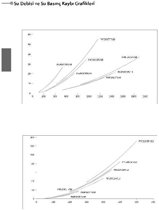
 Water Flow and Pressure Drops Graphics
3 Rows Coil Unit Water Pressure Drop Curve
<![if ! IE]><![endif]>ENGLISH
1 Row Coil System Water Pressure Drop
9
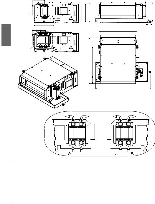
 2. Dimension
157,5
<![if ! IE]><![endif]>125
| <![if ! IE]> <![endif]>ENGLISH |
|
252 |
|
105 |
63 |
||
|
X
| <![if ! IE]> <![endif]>207 |
<![if ! IE]> <![endif]>231 |
<![if ! IE]> <![endif]>247 |
| <![if ! IE]> <![endif]>590 |
<![if ! IE]> <![endif]>387 |
|
<![if ! IE]> <![endif]>85 |
DETAIL-X
OUT
L


 IN
IN 


| <![if ! IE]> <![endif]>34 |
|
| <![if ! IE]> <![endif]>143 |
<![if ! IE]> <![endif]>239 |
|
35 |
B
A
C
OUT
R


 IN
IN 


DIMENSIONS
Model |
A (mm) |
B (mm) |
C (mm) |
Water Inlet |
Water Outlet |
Drain Pan Outlet |
|
|
|
|
|
|
|
FWE02C5(T/F)V1B |
454 |
486 |
705 |
G 3 /4" |
G 3 /4" |
R 3 /4" |
|
|
|
|
|
|
|
FWE03C5(T/F)V1B |
629 |
661 |
875 |
G 3 /4" |
G 3 /4" |
R 3 /4" |
|
|
|
|
|
|
|
FWE04C5(T/F)V1B |
759 |
791 |
1005 |
G 3 /4" |
G 3 /4" |
R 3 /4" |
|
|
|
|
|
|
|
FWE06C5(T/F)V1B |
959 |
991 |
1205 |
G 3 /4" |
G 3 /4" |
R 3 /4" |
|
|
|
|
|
|
|
FWE07C5(T/F)V1B |
1209 |
1241 |
1455 |
G 3 /4" |
G 3 /4" |
R 3 /4" |
|
|
|
|
|
|
|
FWE08C5(T/F)V1B |
1309 |
1341 |
1555 |
G 3 /4" |
G 3 /4" |
R 3 /4" |
|
|
|
|
|
|
|
FWE10C5(T/F)V1B |
1569 |
1601 |
1815 |
G 3 /4" |
G 3 /4" |
R 3 /4" |
|
|
|
|
|
|
|
10
 3. Installation
Delivery Of Unit
•During transportation to delivery of the fancoils in high quality without any damage from Daikin production facilities, proper packaging and controls of the units should be done.
•Immediately after the delivery,check all products carefully. When the damage is seen, specify the event on the carrier’s freight bill and to show damage please request observer from the carrier.
•You can do by telephone or upon person, but always verify on the freight bill.
•To specify the size of damage or loss of the shipped product ,the carrier should be opened under the supervision.
•Report should be prepared in order to claim, by keeping the original report in the receiver a copy of the this report should be forwarded to the transportation company by shipper.
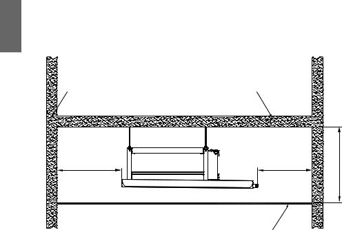
Placement Of The Unit
A ≥ 400 mm B ≥ 200 mm H ≥ 400 mm
OBSTACLE |
OBSTACLE |
<![endif]>ENGLISH
B |
|
A |
<![if ! IE]> <![endif]>H |
|
Figure 2 |
CEILING |
|
|
|
|
CAUTION!
1.Do the following checks before installation and operation.
2.Have adequate space for installation and maintenance. Please refer to the unit size and the connection diagram. (Figure 2 : Gaps around the unit shows the required minimum space.)
3.Make sure you have adequate space for piping and electrical connections.
4.Make sure that the carrier rods can withstand the weight of the unit.
5.For proper operation of the unit and the condensed water discharge , installation of the unit should be done in the horizontal.
6.Channel external static pressure, is designed to be within the range of static pressure
7.The installer must supply service valves and insulation for water piping in accordance with the local code and regulation.
8.People who carry out installation , ensure the service valves local codes and set up according to the rules.
9.Before installation and service transactions are done ,main switch of the unit should
11

|
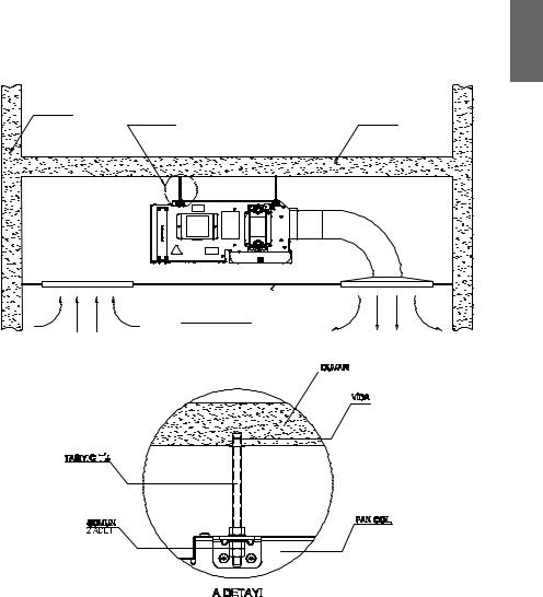
Unit Installation |
|
|
The unit is designed to be installed concealed ceiling and the like. Installation and main- |
|
|
regulation, and experienced with this type of appliance. |
|
|
1. The unit is designed for concealed ceiling installation. |
|
|
3. Make sure that the top of the unit is level. |
|
| <![if ! IE]> <![endif]>ENGLISH |
||
4. Use proper insulation material only. |
||
|
||
|
5. Chilled water pipes and all parts on the pipes should be insulated. |
|
|
6. It is also necessary to insulate air ducts. |
|
|
7. Adhesive for insulation should able to work between -18˚C and 94˚C. |
OBSTACLE
DETAIL A
CEILING ACCESS
PANEL WITH
AIR RETURN
CEILING
RETURN AIR
HANGING
ROD
NUT 2 PCS
OBSTACLE
DISCHANGER AIR
OBSTACLE
EXPANSION SCREW
FANCOIL UNIT
DETAIL A
12
Transportation
1.During transportation and installation of the unit, safety gloves should always be worn and should beware of the damage from sharp edges.
2.The transport process should be done with at least one assistant, and during the transport, protective gloves have to been worn for protecting from sharp edges.
3.If the transport will be made in a crawler, a vehicle with an appropriate lifting and carrying capacity should be preferred.
against falling and tumbling.
Storage
1.If the unit will be stored, it must be protected from external environment conditions. They should not be placed on wet grounds.
2.The temperature of the closed storing areas should be between -10˚C and 60˚C.
3.Until the date to use the unit, it should be stored in its original conditions and should not be removed from the box or package.
Installation
1.During the installation of ceiling concealed fan coil unit, it’s very important that protective helmet and footwear are worn.
2.It is necessary to be cautious about falling pieces and sharp edges that could give damage.
3.During the installation, make sure that there aren’t any missing and damaged parts and not damaged during transport.
4.Lost and damaged parts should be reported and the information about these parts must be provided to the relevant persons.
<![endif]>ENGLISH
13
<![endif]>ENGLISH
CAUTION!
During the installation make sure that the top side of the units is located horizontally. The drain pan is designed with a little gradient to facilitate drain.
Air Duct Connection
1.Circulatory air pressure drop should be within External Static Pressure.
2.Galvanized steel air ducts are suitable.
3.Make sure there is no leak of air.
where the units is being installed.
During the assembly; air duct installation weight should not be transmitted on the unit.
Pipe Connections
1.When the water inlet and outlet connections are made, make sure that there are no hot or cold water on the system and the valves are closed.
2.In case of contact with the hot water, burns may occur on contact area.
4.The lower connection is the water inlet while the upper is the outlet.
5.Seal must be used in water connections against leakage.
6.Drain pipe can be PVC or steel.
7.The suggested slope of the drain pipe is minimum 1:50.
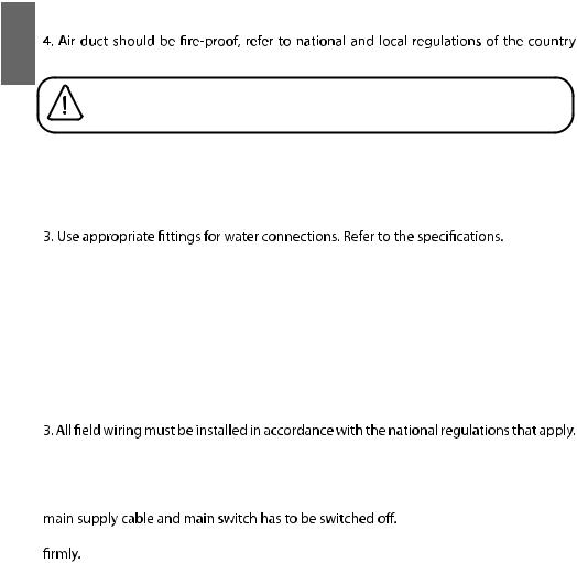
Wiring
1.All wiring connection must be done according to the wiring diagram on the units and inside the manuel.
2.The units must be groundedwell.
4.Power supply cable must be equivalent to H05RN-F (2451EC57) as minimum requirement.
5.Ensure that appropriate voltage value and cables are supplied to the units.
6.While making this unit’s electrical connections, there must not be any energy on the
7.During the installation of electrical connections, make sure the cables are connected
8.An appropriate strain relief unit must be used to attach the power wires to the terminal box.
WARNING!
The responsibilities for any malfunctioning or damage caused by accessories which are not supplied with the unit belong to the supplier of the accessory.
14
 Wiring Diagrams
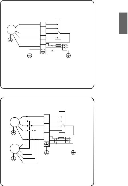
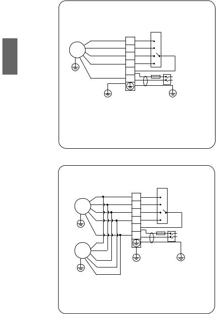
•For FWE02C5(T/F)V1B, FWE03C5(T/F)V1B, FWE04C5(T/F)V1B, FWE06C5(T/F)V1B models,
FWE (02 - 03 - 04 - 06)C5(T/F)V1
ELECTRICAL CIRCUIT DIAGRAM
|
|
|
WIRING |
|
|
|
ORANGE |
LF |
L |
FAN SPEED |
|
|
|
|
|||
|
|
|
SWITCH |
|
|
|
BROWN |
MF |
M |
|
|
M1 |
|
|
|||
|
H |
|
|
||
YELLOW |
|
|
|
||
|
HF |
|
|
||
|
|
|
|
||
|
|
|
|
|
|
|
RED |
SHF |
SH |
|
|
|
|
|
|
||
|
|
|
|
|
|
G / Y |
|
L |
F |
|
|
BLUE |
|
L |
POWER |
||
|
N |
|
|||
|
|
|
N |
SOURCE |
|
|
|
|
|
||
|
|
|
MAIN SWITCH |
|
|
|
G / Y |
|
|
G / Y |
|
NOTE |
|
- - - - - - - |
= FIELD WIRING |
M1, M2 |
= FAN MOTOR |
G / Y |
= GREEN / YELLOW |
F |
= FUSE |
LF |
= LOW SPEED |
MF |
= MEDIUM SPEED |
HF |
= HIGH SPEED |
SHF |
= SUPER HIGH SPEED |
4PW90004-1
• For FWE07C5(T/F)V1B, FWE08C5(T/F)V1B, FWE10C5(T/F)V1B models,
FWE (07 - 08 - 10)C5(T/F)V1
ELECTRICAL CIRCUIT DIAGRAM
|
|
|
WIRING |
|
|
|
ORANGE |
LF |
L |
FAN SPEED |
|
|
|
|
|||
|
|
|
SWITCH |
|
|
|
BROWN |
MF |
M |
|
|
M1 |
|
|
|||
|
H |
|
|
||
YELLOW |
|
|
|
||
|
HF |
|
|
||
|
|
|
|
||
|
|
|
|
|
|
|
RED |
SHF |
SH |
|
|
|
|
|
|
||
G / Y |
|
|
|
|
|
|
L |
|
|
|
|
|
|
F |
|
|
|
|
BLUE |
|
L |
POWER |
|
|
N |
|
|||
|
|
|
N |
SOURCE |
|
M2 |
|
|
MAIN SWITCH |
|
|
|
|
|
|
|
|
G / Y |
G / Y |
G / Y |
|
|
|
NOTE |
|
|
- - - - - - - |
= FIELD WIRING |
|
M1, M2 |
= FAN MOTOR |
|
G / Y |
= GREEN / YELLOW |
|
F |
= FUSE |
|
LF |
= LOW SPEED |
|
MF |
= MEDIUM SPEED |
|
HF |
= HIGH SPEED |
4PW90005-1 |
SHF |
= SUPER HIGH SPEED |
<![endif]>ENGLISH
15

 4. Maintenance
<![endif]>ENGLISH
•General
Installation and maintenance should be performed by qualified persons who are familiar with local code and regulation, and experienced with this type of appliance.
Confirm that the unit has been switched OFF before installing or servicing the unit.
A good general maintenance plan will prevent losses and unexpected failures of the equipment.
Dirty filters reduce air flow as well as unit performance. Thus changing or cleaning the filters is very important. Check the cleanliness of filter and replace or clean monthly.
Coils shall be cleaned from dust, dirt or lint with compressed air, water. They can be brushed with a soft brush and vacuum cleaner.
Units not used during winter season should be drained, or sufficient amount of antifreeze should be added to the water circuit to avoid freezing.
Monthly;
1.Inspect and clean condensate drain pan to avoiding clogging of drainage by dirt, dust, etc. Inspect drainage piping to ensure the proper condensate flow.
2.Check and clean the coil. Clean the coils with low pressure water jet or low pressure air.
3.Clean and tighten all the wiring connections.
4.Drain out the system water and check for build up of mineral deposits.
5.The maintenance of the unit should be done by an authorized service.
6.Contact the authorized service for any work to be done on the unit except the periodic maintenance that is addressed to the user in this booklet.
•In the event that there is any conflict in the interpretation of this manual and any translation of the same in anylanguage,theEnglishversionofthismanualshallprevail.
•Themanufacturerreservestherighttoreviseanyofthespecificationanddesigncontainherein atanytime withoutpriornotification.
16
Değerli Mü terimiz,
DAIKIN ürünlerini seçtiğiniz için te ekkür ederiz.
Bu kurulum kılavuzu, güvenlik, standart i letim ile ilgili açıklamaları içermektedir.
Satın aldığınız Fan Coil’in kurulumu ve i leme almadan önce bakım ve kurulum i lemi için güvenlik ve uyarıları dikkatlice okuyunuz ve kılavuzunuzu saklayınız.
Genel uyarılara önem veriniz.
eğitimli kullanıcılar tarafından veya meslekten olmayan ki ilerce ticari amaçla kullanılmak üzere tasarlanmı tır.
<![endif]>TÜRKÇE
Bu ürün “Atık Elektrikli ve Elektronik Eşyaların Kontrolü
!Yönetmeliği”ne tabidir. Atık ürünler belirlenen aktarma ve geri dönüştürme merkezlerine götürülmelidir. Ayrıntılar
belediyenin ilgili birimine başvurunuz.
AEEE Yönetmeliğine uygundur.
İmalatçı Firma :
Daikin Isıtma ve Soğutma Sistemleri San. Tic. A.ẞ.
Hürriyet Mah. Yakacık D-100 Kuzey Yan Yol No :49/1-2 Kartal/ İSTANBUL/TÜRKİYE
Tel |
: 0216 453 27 00 |
Fax |
: 0216 671 06 00 |
Üretim Yeri :
Daikin Isıtma ve Soğutma Sistemleri San. Tic. A.ẞ. 2. OSB 54300 Hendek/SAKARYA
Tel |
: 0264 616 27 00 |
Fax |
: 0264 654 58 45-46 |
4449990•www.daikin.com.tr
Türkiye’de üretilmi tir.
17
İçindekiler |
|
1. Genel Bilgiler |
20 |
2. Boyutlar |
30 |
3. Kurulum |
31 |
4. Bakım |
36 |
Güvenlik önlemi
Fan Coil ünitesinin kurulumundan önce lütfen a ağıdaki güvenlik önlemlerini dikkatlice okuyunuz.
DİKKAT 
•Kurulum ve devreye alma sırasında deneyimli personel kullanınız. Elektrik ve su bağlantılarını mutlaka ehliyetli bir elektrikçi ve deneyimli bir tesisatçıya yaptırınız.
•Montaj ve kurulum sırasında, ürüne ait kodlama, tip ve beyan etiketlerine dikkat ediniz.
•Tüm bağlantı i lemlerinde uluslararası kodlama ve kablo renk kodlama sistemine uyunuz.
•Ünitenin nasıl i letileceği konusunda emin değilseniz, kurulumunu yapabilecek ki ilerle irtibat kurunuz. Cihaz, sorumlu bir ki i tarafından cihazın kullanımı ile ilgili talimat veya sorumluluk verilmemesi
tecrübe eksikliği ile çocukları da içeren ki ilerin güvenlikleri için o ki iler tarafından kullanılmak üzere tasarlanmamı tır Çocukların cihazla oynamaması için çocuklar kontrol edilmelidir.
•Çalı ma voltaj değerinin ve çekilen güç kablolarının, cihaz değerlerine uygun olmasını sağlayınız. Aksi durumda cihazın zarar görmesine neden olabilirsiniz.
•Yüksek voltaj kategori III artlarında, ana alter ya da diğer bir ifade ile ayırıcı bağlantıların tüm kutupları birbirinden ayrılmı ve kablolar sabitlenmi olmalıdır.
•Cihazın topraklamasını mutlaka yapınız. Aksi takdirde cihazın zarar görmesine, yaralanma ve ölümle sonuçlanacak kazalara sebebiyet verebilirsiniz.
•Cihazın elektriksel bağlantıları yapılırken, ana besleme kablosunda enerji olmamalı ve cihazın ana alteri kapalı konumda olmalıdır.
•Elektrik bağlantılarının yapılması sırasında kabloların iyice sabitlendiğinden ve sıkıca bağlı olduğundan emin olunuz.
•Tüm kontrolleri yaptıktan sonra cihazı devreye alınız.
•Montaj ve kurulum kılavuzunu kullanarak cihaz tamiri yapmaya çalı mayınız. Bu kılavuz içerisinde cihazın tamir konuları bulunmamaktadır.
•Bakanlıkça tespit ve ilan edilen kullanım ömrü 10 yıldır.(Ürünün fonksiyonunu yerine getirebilmesi için gerekli yedek parça bulundurma süresi. )
•Elektrik bağlantılarına zarar vermemek için elektrik bağlantılarının gergin olmamasına dikkat ediniz.
Cihazınızın Ta ınması İle İlgili Uyarılar:
•Cihazınızı a ırı titre im ve darbelerden koruyunuz.
•Cihazınızın su altında kalmaması için gereken önlemleri alınız.
•Cihazı kolilerin üzerinde bulunan evrensel ta ıma uyarı ve i aretlerine dikkat ederek ta ıyınız.
19
 1. Genel Bilgiler
<![endif]>TÜRKÇE
DAIKIN gizli tavan tipi fancoiller 7 farklı tipte ve 2, 4 borulu olmak üzere toplam 14 farklı kapasitede üretilmektedir. Kanallı ve serbest basma uygulamaları için uygundur. Standart olarak 0 – 30 Pa, isteğe bağlı olarak 60 – 80 Pa harici statik hava basınç kaybına göre üretim yapılmaktadır.
Sessiz çalı ması, kompakt ölçüsü özellikle dü ük ağırlığı sayesinde asma tavan
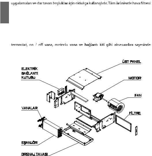
standart olarak bulunmakta ve farklı 3 konumdan rahatlıkla servis verebilmektedir. Motorlu vana ve 2 – 3 – 4 yollu vana uygulamaları için uzun drenaj tavası bulunmaktadır. Tava sıvama yöntemi ile üretilmi olup yoğu malara kar ı dı ı özel yalıtım malzemesi ile izole edilmi , iç kısım ise elektrostatik toz boya ile boyanmı tır. Öne eğimli kanatları ile santrifüj fanları statik ve dinamik olarak dengelenmi tir. Standart olarak 4 hız kademeli ve mono faz elektrik motoru kullanılmaktadır. (Şekil 1)
Sahada servis bağlantı tarafının kolaylıkla deği tirilebilmesi, mekanik – elektronik
maksimum esneklik ve montaj kolaylığı sağlamaktadır.
ẞekil 1
20
Teknik Özellikler
|
|
2 Borulu |
|
FWE02C5TV1B |
FWE03C5TV1B |
FWE04C5TV1B |
FWE06C5TV1B |
FWE07C5TV1B |
FWE08C5TV1B |
FWE10C5TV1B |
|
|
|
|
|
|
|
|
|
|
|
|
|
|
|
Güç Kaynağı |
|
|
|
220-240V / 1 ~ / 50 Hz |
|
|
|||
|
|
|
|
|
|
|
|
|
|
|
|
|
|
Süper Yüksek Hız |
|
430 |
638 |
910 |
1195 |
1559 |
1753 |
2177 |
|
|
|
|
|
|
|
|
|
|
|
|
|
Hava |
|
Yüksek Hız |
|
311 |
518 |
619 |
926 |
1188 |
1413 |
1735 |
|
|
|
|
|
|
|
|
|
|
|
|
|
Debisi |
|
Orta Hız |
|
238 |
385 |
413 |
630 |
851 |
1016 |
1202 |
|
|
|
|
|||||||||
|
|
|
|
|
|
|
|
|
|
|
|
|
|
Dü ük Hız |
|
150 |
256 |
284 |
426 |
569 |
688 |
808 |
|
|
|
|
|
|
|
|
|
|
|
|
|
|
|
Soğutma |
Toplam |
|
2,17 |
3,22 |
4,34 |
6,06 |
6,83 |
7,84 |
9,96 |
|
|
|
|
|
|
|
|
|
|
|
|
Kapasite |
|
Duyulur |
kW |
1,61 |
2,44 |
3,27 |
4,55 |
4,83 |
6,02 |
7,58 |
|
|
|
||||||||||
|
|
|
|
|
|
|
|
|
|
|
|
|
|
Isıtma |
|
2,79 |
4,28 |
5,61 |
7,66 |
9,26 |
10,50 |
13,00 |
|
|
|
|
|
|
|
|
|
|
|
|
|
Su Debisi |
|
Soğutma |
l/s |
0,10 |
0,15 |
0,21 |
0,29 |
0,33 |
0,38 |
0,48 |
|
|
|
|
|
|
|
|
|
|
|
||
|
Isıtma |
0,07 |
0,10 |
0,14 |
0,19 |
0,23 |
0,26 |
0,33 |
|||
|
|
|
|||||||||
|
|
|
|
|
|
|
|
|
|
|
|
Su Basınç |
|
Soğutma |
kPa |
15,1 |
11,7 |
23,9 |
46,4 |
14,8 |
19,3 |
32,9 |
|
|
|
|
|
|
|
|
|
|
|
||
Kaybı |
|
Isıtma |
6,1 |
4,9 |
9,7 |
17,9 |
6,6 |
8,4 |
13,7 |
||
|
|
||||||||||
|
|
|
|||||||||
|
|
|
|
|
|
|
|
|
|
|
|
|
Çekilen Güç (0 Pa) |
kW |
0,046 |
0,069 |
0,083 |
0,119 |
0,163 |
0,181 |
0,230 |
||
|
|
|
|
|
|
|
|
|
|
|
|
|
|
Süper Yüksek Hız |
|
51 |
61 |
58 |
62 |
62 |
64 |
65 |
|
|
|
|
|
|
|
|
|
|
|
|
|
Ses Gücü |
|
Yüksek Hız |
|
49 |
56 |
48 |
55 |
57 |
58 |
60 |
|
|
|
|
dB(A) |
|
|
|
|
|
|
|
|
Seviyesi |
|
Orta Hız |
37 |
49 |
38 |
46 |
47 |
50 |
50 |
||
|
|
||||||||||
|
|
|
|||||||||
|
|
|
|
|
|
|
|
|
|
|
|
|
|
Dü ük Hız |
|
31 |
38 |
32 |
39 |
38 |
41 |
40 |
|
|
|
|
|
|
|
|
|
|
|
|
|
|
|
Süper Yüksek Hız |
|
41 |
51 |
48 |
52 |
52 |
54 |
55 |
|
Ses |
|
|
|
|
|
|
|
|
|
|
|
|
Yüksek Hız |
|
39 |
46 |
38 |
45 |
47 |
48 |
49 |
||
Basıncı |
|
|
|
dB(A) |
|
|
|
|
|
|
|
|
Orta Hız |
26 |
39 |
28 |
36 |
37 |
40 |
39 |
|||
Seviyesi |
|
|
|||||||||
|
|
|
|
|
|
|
|
|
|
|
|
|
|
Dü ük Hız |
|
21 |
28 |
22 |
29 |
27 |
31 |
29 |
|
|
|
|
|
|
|
|
|
|
|
|
|
|
|
Geni lik |
|
590 |
590 |
590 |
590 |
590 |
590 |
590 |
|
Ünite |
|
|
|
|
|
|
|
|
|
|
|
|
Yükseklik |
mm |
253 |
253 |
253 |
253 |
253 |
253 |
253 |
||
Boyutları |
|
||||||||||
|
|
|
|
|
|
|
|
|
|
|
|
|
|
Derinlik |
|
705 |
875 |
1005 |
1205 |
1455 |
1555 |
1815 |
|
|
|
|
|
|
|
|
|
|
|
|
|
|
|
Geni lik |
|
605 |
605 |
605 |
605 |
605 |
605 |
605 |
|
Paketlenmi |
|
|
|
|
|
|
|
|
|
||
Yükseklik |
|
|
|
|
|
|
|
|
|||
Cihaz |
|
mm |
260 |
260 |
260 |
260 |
260 |
260 |
260 |
||
Boyutları |
|
|
|
|
|
|
|
|
|
|
|
|
Derinlik |
|
720 |
890 |
1020 |
1220 |
1470 |
1570 |
1830 |
||
|
|
|
|||||||||
|
|
|
|
|
|
|
|
|
|
|
|
Ağırlık |
|
Net |
Kg |
18 |
21 |
25 |
30 |
39 |
42 |
47 |
|
|
|
|
|
|
|
|
|
|
|
||
|
Brüt |
20 |
23 |
27 |
33 |
42 |
45 |
51 |
|||
|
|
|
|||||||||
|
|
|
|
|
|
|
|
|
|
|
|
<![endif]>TÜRKÇE
Soğutma için hava sıcaklığı 27 / 19 °C KT / YT ve 7 / 12 °C su giri / çıkı sıcaklığı. Isıtma için hava sıcaklığı 20 / 15 °C KT / YT ve 50 / 40 °C su giri / çıkı sıcaklığı. En yüksek hız modundaki kapasite değerleridir.
Ses basıncı seviyesi değerleri ünite hava çıkı ından 1 m uzaklıkta ölçülmü tür. Harici statik basınç “0 Pa” dır.
21
Teknik Özellikler
<![endif]>TÜRKÇE
|
4 Borulu |
|
FWE02C5FV1B |
FWE03C5FV1B |
FWE04C5FV1B |
FWE06C5FV1B |
FWE07C5FV1B |
FWE08C5FV1B |
FWE10C5FV1B |
||
|
|
|
|
|
|
|
|
|
|
|
|
|
Güç Kaynağı |
|
|
|
220-240V / 1 ~ / 50 |
Hz |
|
|
|||
|
|
|
|
|
|
|
|
|
|
|
|
|
Süper Yüksek Hız |
|
416 |
626 |
835 |
1193 |
1548 |
1742 |
2166 |
||
|
|
|
|
|
|
|
|
|
|
|
|
Hava Debisi |
Yüksek Hız |
|
302 |
501 |
571 |
905 |
1173 |
1386 |
1729 |
||
|
|
|
|
|
|
|
|
|
|
||
Orta Hız |
|
232 |
371 |
377 |
618 |
846 |
1001 |
1199 |
|||
|
|
||||||||||
|
|
|
|
|
|
|
|
|
|
|
|
|
Dü ük Hız |
|
142 |
256 |
257 |
414 |
569 |
684 |
804 |
||
|
|
|
|
|
|
|
|
|
|
|
|
|
|
Toplam |
|
2,100 |
3,160 |
3,980 |
6,050 |
6,780 |
7,790 |
9,910 |
|
Kapasite |
Soğutma |
|
kW |
|
|
|
|
|
|
|
|
Duyulur |
1,550 |
2,370 |
3,190 |
4,490 |
5,160 |
5,910 |
7,450 |
||||
|
|||||||||||
|
|
|
|||||||||
|
|
|
|
|
|
|
|
|
|
|
|
|
Isıtma |
|
2,300 |
3,530 |
4,560 |
6,170 |
7,600 |
8,520 |
10,400 |
||
|
|
|
|
|
|
|
|
|
|
||
Su Debisi |
Soğutma |
l/s |
0,10 |
0,15 |
0,20 |
0,29 |
0,33 |
0,37 |
0,48 |
||
|
|
|
|
|
|
|
|
|
|||
Isıtma |
0,03 |
0,05 |
0,06 |
0,09 |
0,12 |
0,13 |
0,16 |
||||
|
|
||||||||||
|
|
|
|
|
|
|
|
|
|
|
|
Su Basınç Kaybı – Soğutma Bataryası |
kPa |
14,5 |
11,4 |
21,6 |
46,3 |
14,6 |
19,1 |
32,7 |
|||
|
|
|
|
|
|
|
|
|
|||
Su Basınç Kaybı – Isıtma Bataryası |
kPa |
3,6 |
8,8 |
15,6 |
31,8 |
58,6 |
74,6 |
123,0 |
|||
|
|
|
|
|
|
|
|
|
|||
Çekilen Güç (0Pa) |
kW |
0,046 |
0,069 |
0,083 |
0,119 |
0,163 |
0,181 |
0,230 |
|||
|
|
|
|
|
|
|
|
|
|
||
|
Süper Yüksek Hız |
|
51 |
61 |
58 |
62 |
62 |
64 |
65 |
||
|
|
|
|
|
|
|
|
|
|
||
Ses Gücü |
Yüksek Hız |
|
49 |
56 |
48 |
55 |
57 |
58 |
60 |
||
|
|
dB(A) |
|
|
|
|
|
|
|
||
Seviyesi |
Orta Hız |
37 |
49 |
38 |
46 |
47 |
50 |
50 |
|||
|
|||||||||||
|
|
||||||||||
|
|
|
|
|
|
|
|
|
|
||
|
Dü ük Hız |
|
31 |
38 |
32 |
39 |
38 |
41 |
40 |
||
|
|
|
|
|
|
|
|
|
|
||
|
Süper Yüksek Hız |
|
41 |
51 |
48 |
52 |
52 |
54 |
55 |
||
|
|
|
|
|
|
|
|
|
|
||
Ses Basıncı |
Yüksek Hız |
dB(A) |
39 |
46 |
38 |
45 |
47 |
48 |
49 |
||
|
|
|
|
|
|
|
|
|
|||
Seviyesi |
Orta Hız |
26 |
39 |
28 |
36 |
37 |
40 |
39 |
|||
|
|||||||||||
|
|
||||||||||
|
|
|
|
|
|
|
|
|
|
||
|
Dü ük Hız |
|
21 |
28 |
22 |
29 |
27 |
31 |
29 |
||
|
|
|
|
|
|
|
|
|
|
||
|
Geni lik |
|
590 |
590 |
590 |
590 |
590 |
590 |
590 |
||
Ünite |
|
|
|
|
|
|
|
|
|
|
|
Yükseklik |
mm |
253 |
253 |
253 |
253 |
253 |
253 |
253 |
|||
Boyutları |
|||||||||||
|
|
|
|
|
|
|
|
|
|
||
|
Derinlik |
|
705 |
875 |
1005 |
1205 |
1455 |
1555 |
1815 |
||
|
|
|
|
|
|
|
|
|
|
||
|
Geni lik |
|
605 |
605 |
605 |
605 |
605 |
605 |
605 |
||
Paketlenmi |
|
|
|
|
|
|
|
|
|
|
|
Yükseklik |
mm |
260 |
260 |
260 |
260 |
260 |
260 |
260 |
|||
Boyutlar |
|||||||||||
|
|
|
|
|
|
|
|
|
|
||
|
Derinlik |
|
720 |
890 |
1020 |
1220 |
1470 |
1570 |
1830 |
||
|
|
|
|
|
|
|
|
|
|
||
Ağırlık |
Net |
Kg |
19 |
22 |
26 |
31 |
41 |
43 |
50 |
||
|
|
|
|
|
|
|
|
|
|||
Brüt |
21 |
24 |
28 |
34 |
45 |
47 |
54 |
||||
|
|
||||||||||
|
|
|
|
|
|
|
|
|
|
|
|
Soğutma için hava sıcaklığı 27 / 19 °C KT / YT ve 7 / 12 °C su giri / çıkı sıcaklığı.
Isıtma için hava sıcaklığı 20 / 15 °C KT / YT ve 50 / 40 °C su giri / çıkı sıcaklığı.
En yüksek hız modundaki kapasite değerleridir.
Ses basıncı seviyesi değerleri ünite hava çıkı ından 1 m uzaklıkta ölçülmü tür.
Harici statik basınç “0 Pa” dır.
22

Kalınlık (mm) |
Kalınlık (mm) |
Kalınlık (mm) |
Kalınlık (mm) |
Kalınlık (mm) |
Kalınlık (mm) |
3 Sıralı Isı Deği tirici Su Basınç Kaybı Eğrileri
| <![if ! IE]> <![endif]>TÜRKÇE |
<![if ! IE]> <![endif]>BasınçKaybı kPa |
|
<![if ! IE]> <![endif]>Su |
Su Debisi kg/h
1 Sıralı Isı Deği tirici Su Basınç Kaybı Eğrileri
<![if ! IE]><![endif]>Su Basınç Kaybı kPa
Su Debisi kg/h
24

 2. Boyutlar
157,5
<![if ! IE]><![endif]>125
252
105 63
X
| <![if ! IE]> <![endif]>207 |
<![if ! IE]> <![endif]>231 |
<![if ! IE]> <![endif]>247 |
| <![if ! IE]> <![endif]>590 |
<![if ! IE]> <![endif]>387 |
|
<![if ! IE]> <![endif]>85 |
X-DETAYI
OUT
L


 IN
IN 


| <![if ! IE]> <![endif]>34 |
|
| <![if ! IE]> <![endif]>143 |
<![if ! IE]> <![endif]>239 |
|
35 |
B
A
C
OUT
R


 IN
IN 


BOYUTLAR
Model |
A (mm) |
B (mm) |
C (mm) |
Su Giri i |
Su Çıkı ı |
Tava |
Çıkı ı |
|
|
|
|
|
|
|
|
FWE02C5(T/F)V1B |
454 |
486 |
705 |
G 3 /4" |
G 3 /4" |
R 3 |
/4" |
|
|
|
|
|
|
|
|
FWE03C5(T/F)V1B |
629 |
661 |
875 |
G 3 /4" |
G 3 /4" |
R3 /4" |
|
|
|
|
|
|
|
|
|
FWE04C5(T/F)V1B |
759 |
791 |
1005 |
G 3 /4" |
G 3 /4" |
R 3 |
/4" |
|
|
|
|
|
|
|
|
FWE06C5(T/F)V1B |
959 |
991 |
1205 |
G 3 /4" |
G 3 /4" |
R 3 |
/4" |
|
|
|
|
|
|
|
|
FWE07C5(T/F)V1B |
1209 |
1241 |
1455 |
G 3 /4" |
G 3 /4" |
R3 /4" |
|
|
|
|
|
|
|
|
|
FWE08C5(T/F)V1B |
1309 |
1341 |
1555 |
G 3 /4" |
G 3 /4" |
R3 /4" |
|
|
|
|
|
|
|
|
|
FWE10C5(T/F)V1B |
1569 |
1601 |
1815 |
G 3 /4" |
G 3 /4" |
R3 /4" |
|
|
|
|
|
|
|
|
|
<![endif]>TÜRKÇE
25
 3. Kurulum
Cihaz Teslimatı
<![endif]>TÜRKÇE
•Fan Coil üniteleri ta ıma sırasında zarar görmeden kaliteli ürün sevkiyatı için DAIKIN üretim tesisinden ayrılırken uygun paketlemesi ve kontrolleri yapılır.
•Teslimattan hemen sonra tüm ürünleri dikkatlice inceleyiniz. Hasar görüldüğü zaman, ta ıyıcının irsaliyesinde bu olayı belirtin ve hasarı göstermek için ta ıyıcıdan gözlemci talep edin. Bunu telefonla veya ahıs aracılığıyla yapabilirsiniz ama her zaman irsaliyedekini doğrulayınız.
•Hasar veya kaybın büyüklüğünü belirtmek için sevk edilen ürün ta ıyıcı gözetiminde açılmalı, hak talep edilmesi amacıyla rapor tutulmalı, aslı alıcıda kalarak bir kopyası nakliyeci tarafından ta ıyıcı irkete iletilmelidir.
Cihaz Yerle imi
A ≥ 400 mm B ≥ 200 mm H ≥ 400 mm
DUVAR |
TAVAN |
B |
|
A |
<![if ! IE]> <![endif]>H |
|
ẞekil-2 |
ASMA TAVAN |
|
|
|
|
DİKKAT!
1.Kurulum ve çalı tırma i leminden önce a ağıdaki kontrolleri yapınız;
2.Kurulum ve bakım için yeterli bo luk olmalıdır. Lütfen ünite ölçülerine ve bağlantıemasına bakınız. (Şekil 2: Ünitenin etrafında bırakılması gereken minimum boşlukları gösterir.)
3.Borulama ve elektrik bağlantısı için yeterli bo luğun olduğundan emin olunmalıdır.
4.Ta ıyıcı tijlerin cihazın ağırlığına dayanabileceğinden emin olunmalıdır.
5.Cihazın düzgün çalı ması ve yoğu an suyun bo alımı için cihaz yatay pozisyonda kurulumu yapılmalıdır.
6.Kanalın harici statik basıncı, dizayn statik basıncı aralığının içinde olmalıdır.
7.Kurulumu gerçekle tirecek ki iler, servis vanalarını, yerel kodlara ve kurallara göre kurulumunu sağlamalıdırlar.
8.Kurulum ve servis i lemleri yapılmadan önce cihazın ana anahtarının kapalı konumda olduğu doğrulanmalıdır.
26
Ünitenin Kurulumu
Kurulum ve devreye alma sırasında deneyimli personel kullanınız. Elektrik ve su bağlantılarını mutlaka ehliyetli bir elektrikçi ve deneyimli bir tesisatçıya yaptırınız.
1. Cihaz gizli tavan uygulamaları için tasarlanmı tır. |
|
|
|
2. Cihazı asmak için üstünde delikler bulunmaktadır. |
|
|
|
3. Cihazın üst kısmının dengede olmasına dikkat edilmelidir. |
|
|
|
4. Borulamada uygun yalıtım malzemesi kullanılmalıdır. |
|
|
|
5. Su boruları ve borular üzerindeki bütün parçalar yalıtılmalıdır. |
|
|
|
6. Hava kanallarının da yalıtılması gerekmektedir. |
|
<![if ! IE]> <![endif]>TÜRKÇE |
|
7. Yalıtım için kullanılan yapı tırıcı -18˚C ve 94˚C sıcaklığına dayanıklı olmalıdır. |
|||
|
|||
DUVAR |
TAVAN |
|
|
A DETAYI |
|
||
SERVİS PANELİ
ASMA TAVAN
EMİẞ |
|
|
|
|
|
|
|
|
|
|
|
|
|
|
|
|
ÜFLEME |
||||||
|
|
|
|
|
|
|
|
|
|
|
|
|
|
|
|
|
|
|
|
|
|
|
|
|
|
|
|
|
|
|
|
|
|
|
|
|
|
|
|
|
|
|
|
|
|
|
|
|
|
|
|
|
|
|
|
|
|
|
|
|
|
|
|
|
|
|
|
|
|
|
|
|
|
|
|
|
|
|
|
|
|
|
|
|
|
|
|
|
|
|
|
|
|
|
|
|
|
|
|
|
|
|
|
|
|
|
|
|
|
|
|
|
|
|
|
|
|
|
|
|
|
|
|
|
|
|
|
|
|
|
|
|
|
|
|
|
|
|
|
|
|
|
|
|
|
|
|
|
|
|
|
|
|
|
|
|
|
|
|
|
|
|
|
|
|
|
|
27

<![endif]>TÜRKÇE
Ta ıma
1.Cihazın ta ınması ve montaj yapılması sırasında mutlaka koruyucu eldiven giyilmeli ve sivri kenarların zarar vermesinden mutlaka sakınılmalıdır.
2.Ta ıma i lemi en az bir yardımcı ile yapılmalı, ta ıma sırasında koruyucu eldiven takılarak keskin ve sivri kenarların verebileceği zararlardan sakınılmalıdır.
3.Ta ıma paletli olarak yapılacak ise uygun kapasitede kaldırma ve ta ıma aracı seçilmelidir.
4.Ta ıma öncesi ve ta ıma sırasında, dü me ve devrilmeye kar ı cihazlar uygun bir ekilde sabitlenerek koruma önlemleri alınmalıdır.
Depolama
1.Cihazların depolanması ve montaj için bekletilmesi gerekli ise, dı ortam artlarından korunmalı, nemli ve ıslak zemine konulmamalıdır.
2.Bu nedenle oda sıcaklığının -10˚C ile 60˚C arasında olduğu kapalı mahallerde bekletilmelidir.
3.Cihaz kullanılacağı zamana kadar kutusundan veya paketinden çıkartılmamalı ve orijinal hali ile muhafaza edilmelidir.
Montaj
1.Tavan tipi fancoil cihazının montajı sırasında mutlaka koruyucu ba lık takılmalı, koruyucu ayakkabı giyilmelidir.
2.Dü ebilecek parçalardan ve sivri kenarların verebileceği zararlardan sakınılmalıdır.
3.Montaj sırasında eksik ve hasarlı parça olmadığından ve ta ıma sırasında zarar görmediğinden emin olunmalıdır.
4.Kayıp, hasarlı ve zarar görmü parçalar için rapor tutulmalı ve ilgili personele bilgi verilip rapor onaylatılmalıdır.
28
DİKKAT!
Kurulum a amasında cihazın üst kısmının yatay konuma getirilmesine dikkat ediniz çünkü yoğu ma tavası yoğu an suyun bo altımı için çok az eğimli dizayn edilmi tir.
Hava Kanalı Bağlantısı
1.Dola an hava basıncı, harici statik basıncın içinde kalmalıdır.
2.Hava kanallarının galvanizli çelikten imal edilmi olması uygundur.
3.Hava kaçağı olmadığından emin olunmalıdır.
4.Hava kanalı yangına dayanıklı olmalı, ilgili ülkenin ulusal ve yerel yönetmelikleri tercih edilmelidir.
 Montaj esnasında; hava kanalı tesisatının ağırlığı cihaza ta ıtılmamalıdır.
Boru Bağlantıları
1.Su giri i ve çıkı bağlantıları yapılırken, sistemde sıcak veya soğuk su bulunmadığından ve vanaların kapalı olduğundan mutlaka emin olunmalıdır.
2.Sıcak su ile temas edilmesi durumunda temas noktalarında yanık olu umu meydana gelebilir.
3.Su bağlantıları için uygun boru bağlantı parçalar kullanılmalıdır.
4.Su giri i altta, çıkı ı üstte olmalıdır.
5.Su bağlantılarını yaparken mutlaka conta kullanılmalıdır.
6.Drenaj borusu PVC veya çelik olabilir.
7.Drenaj borusunda tavsiye edilen eğim en az 1:50 olmalıdır.
Elektrik Bağlantıları
1.Tüm elektriksel bağlantıları kılavuz içerisinde ve cihaz üzerinde bulunan emalara göre yapılmalıdır.
2.Cihazın topraklaması mutlaka yapılmalıdır.
3.Saha elektrik bağlantıları ulusal güvenlik kanun ve yönetmeliklerine uygun olarak yapılmalıdır.
4.Çalı ma voltaj değerinin ve çekilen güç kablolarının cihaz değerlerine uygun olması sağlanmalıdır.
5.Cihazın elektriksel bağlantıları yapılırken ana besleme kablosunda enerji olmamalıdır ve cihazın ana anahtarı kapalı konumda olmalıdır.
6.Elektrik besleme kablosu, minimum gereksinim olan, H05RN-F (2451EC57)’ye e değer olmalıdır.
7.Elektrik bağlantıların yapılması sırasında kabloların iyice sabitlendiğinden ve sıkıca bağlı olduğundan emin olunmalıdır.
8.Terminal kablo bağlantılarını yaparken kablo kelepçesi mutlaka kullanılmalıdır.
Kurulum ve servis i lemleri yapılmadan önce cihazın ana anahtarının kapalı konumda olduğu doğrulanmalıdır.
DİKKAT!
sorumlu değildir.
<![endif]>TÜRKÇE
29
 Elektrik ẞeması
•FWE02C5(T/F)V1B, FWE03C5(T/F)V1B, FWE04C5(T/F)V1B, FWE06C5(T/F)V1B modelleri için;
<![endif]>TÜRKÇE
FWE (02 - 03 - 04 - 06) C5(T/F)V1 |
|
|
|||
ELEKTRİK DEVRE ŞEMASI |
|
|
|
||
|
|
|
KABLOLAMA /WIRING |
|
|
|
TURUNCU / ORANGE |
LF |
L |
FAN HIZ ANAHTARI |
|
|
|
|
|||
|
|
|
/ FAN SPEED |
||
|
KAHVE / BROWN |
|
M |
||
M1 |
MF |
SWITCH |
|
||
|
H |
|
|||
SARI / YELLOW |
|
|
|
||
|
HF |
|
|
||
|
|
|
|
||
|
|
|
|
|
|
|
KIRMIZI / RED |
SHF |
SH |
|
|
|
|
|
|
||
|
|
|
|
|
|
G / Y |
|
L |
F |
|
|
MAVİ / BLUE |
|
L |
GÜÇ KAYNAĞI / |
||
|
N |
|
|||
|
|
|
N |
POWER |
|
|
|
|
|
||
|
|
|
|
|
SOURCE |
|
|
|
ANA ANAHTAR / |
|
|
|
|
|
MAIN SWITCH |
|
|
|
G / Y |
|
|
G / Y |
|
NOT / NOTE
- - - - - - - = SAHA KABLOLAMASI / FIELD WIRING M1, M2 = FAN MOTOR
G / Y = YEŞİL / SARI - GREEN / YELLOW
F= SİGORTA / FUSE
LF |
= DÜŞÜK HIZ / LOW SPEED |
MF |
= ORTA HIZ / MEDIUM SPEED |
HF |
= YÜKSEK HIZ / HIGH SPEED |
SHF |
= SÜPER YÜKSEK HIZ / SUPER HIGH SPEED |
4PW90004-1
• FWE07C5(T/F)V1B, FWE08C5(T/F)V1B, FWE10C5(T/F)V1B modelleri için;
FWE (07 - 08 - 10) C5(T/F)V1
ELEKTRİK DEVRE ŞEMASI
|
|
|
KABLOLAMA /WIRING |
|
|
|
TURUNCU / |
LF |
L |
FAN HIZ ANAHTARI |
|
|
ORANGE |
|
|||
|
|
/ FAN SPEED |
|||
|
|
M |
|||
|
KAHVE / |
|
|||
M1 |
MF |
SWITCH |
|
||
BROWN |
H |
|
|||
|
|
|
|||
|
SARI / |
HF |
|
|
|
|
|
|
|
||
|
YELLOW |
|
|
|
|
|
|
SH |
|
|
|
|
KIRMIZI / |
SHF |
|
|
|
|
|
|
|
||
G / Y |
RED |
L |
|
|
|
|
|
F |
|
|
|
|
MAVİ / |
|
L |
GÜÇ KAYNAĞI / |
|
|
N |
|
|||
|
BLUE |
|
N |
POWER |
|
|
|
|
|
|
SOURCE |
M2 |
|
|
ANA ANAHTAR / |
|
|
|
|
MAIN SWITCH |
|
|
|
G / Y |
G / Y |
G / Y |
|
|
|
NOT / NOTE |
|
|
- - - - - - - = SAHA KABLOLAMASI / FIELD WIRING M1, M2 = FAN MOTOR
G / Y = YEŞİL / SARI - GREEN / YELLOW
F= SİGORTA / FUSE
LF |
= DÜŞÜK HIZ / LOW SPEED |
MF |
= ORTA HIZ / MEDIUM SPEED |
HF |
= YÜKSEK HIZ / HIGH SPEED |
SHF |
= SÜPER YÜKSEK HIZ / SUPER HIGH SPEED |
4PW90005-1
30
 Loading...