


INSTALLATION AND OPERATION MANUAL
Standard electronic controller
Manuale d'installazione e d'uso
FWEC1 COMANDO LCD PER TERMINALI
Installation and operation manual FWEC1 LCD CONTROLLER FOR INDOOR UNITS
Manuel d'installation et d'utilisation FWEC1 CONTRÔLEUR LCD POUR UNITÉS TERMINALES
Installationsund Bedienungsanleitung
FWEC1 LCD-STEUERUNG FÜR TERMINALS
Manual de instalación y operación
FWEC1 MANDO LCD PARA TERMINALES
Manual de instalação e de funcionamento
FWEC1 COMANDO LCD PARA TERMINAIS
Montagehandleiding en gebruiksaanwijzing
FWEC1 LCD BEDIENING VOOR TERMINALS
MÛKÖDÉSBE HELYEZÉS ÉS KARBANTARTÁS
FWEC1 LCD VEZÉRLŐ TERMINÁLOKHOZ
ИНСТРУКЦИЯ ПО МОНТАЖУ И ЭКСПЛУАТАЦИИ FWEC1 Ж (LCD) ПАНЕЛЬ УПРАВЛЕНИЯ ДЛЯ ТЕРМИНАЛОВ
Italiano
English
Français
Deutsch
Español
Portugues
Nederlands
Hungarian
русский
FWEC1 LCD
(1)
(2)
(3)
1
2
3
4 |
|
5 |
|
|
|
6

NOTES
FWEC1 |
Standard electronic controller |
Manuale d'installazione e d'uso
CARATTERISTICHE GENERALI
Il comando LCD è progettato per comandare tutti i terminali d’impianto con motore asincrono monofase plurivelocità.
FUNZIONI PRINCIPALI E DOTAZIONE
■Regolazione della temperatura dell’aria tramite variazione automatica della velocità del ventilatore.
■Regolazione della temperatura dell’aria tramite on-off del ventilatore ad una velocità fissa.
■Gestione di valvole On/Off per impianti a due o quattro tubi.
■Gestione di resistenza per supporto in riscaldamento.
■Commutazione Raffreddamento/Riscaldamento nelle seguenti modalità:
-manuale a bordo
-manuale a distanza (centralizzato)
-automatica, in funzione della temperatura dell’acqua
-automatica, in funzione della temperatura dell’aria
Inoltre è dotato di:
■Ingresso digitale 1 - Contatti puliti per commutazione Raffreddamento/Riscaldamento remota centralizzata (logica contatto: vedi parametri configurazione scheda).
■Ingresso dogitale 2 - Contatti puliti per consenso esterno (ad esempio; contatto finestra, ON/OFF remoto, sensore di presenza ecc.) che può abilitare o disabilitare il funzionamento dell’unità (logica contatto: vedi parametri configurazione scheda).
■Sonda remota di temperatura per l’acqua (FWTSK).
■Sonda remota di temperatura per l’aria (FWTSK) (tale sonda, se presente, viene utilizzata al posto di quella interna, per la lettura della temperatura ambiente).
Il pannello di comando è composto da:
■Display LCD
■Tastiera
____________________________________________________________
Questo apparecchio non è previsto per essere utilizzato da bambini o da persone con problemi fisici, sensoriali o mentali, inesperte o impreparate, in mancanza di supervisione.
Fare attenzione affinché i bambini non abbiano accesso all'apparecchio.
____________________________________________________________
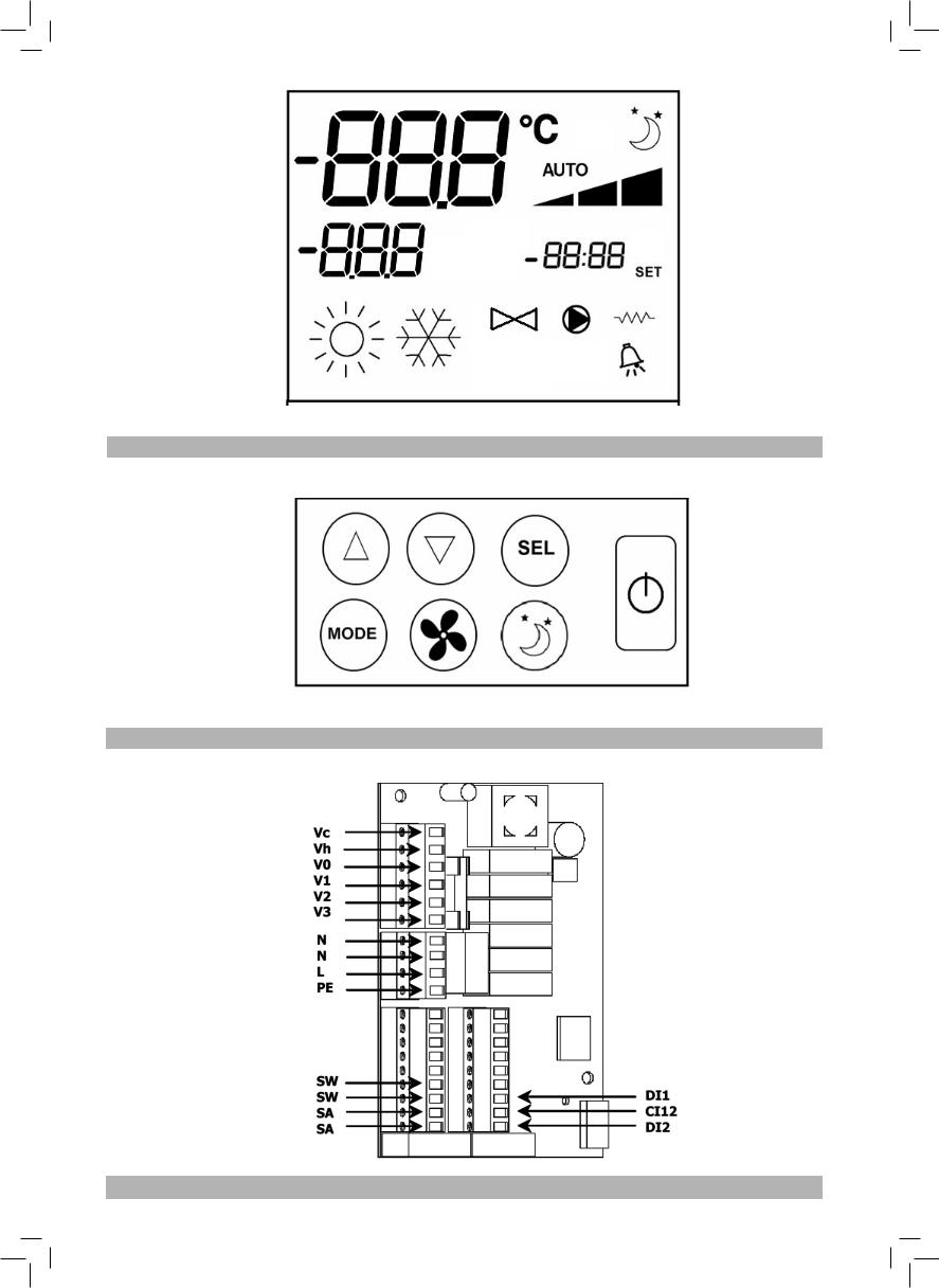
TASTIERA (VEDI FIGURA 2)
Tasto On/Off: accensione/spegnimento termostato. Durante la procedura di modifica parametri permette di tornare al funzionamento normale
Tasti Up e Down: modifica della temperatura di regolazione del Termostato (Riscaldamento:[5.0- 30.0°C], Raffreddamento:[10.0-35.0°C]). Durante la procedura di modifica parametri vengono utilizzati per selezionare i parametri o modificarne il valore
Tasto SEL: in modalità Riscaldamento selezione della resistenza elettrica come funzione ausiliaria
Tasto Mode: selezione della modalità di funzionamento Riscaldamento / Raffreddamento
Tasto Fan: selezione della velocità di funzionamento
Tasto EC: selezione modalità Economy
DISPLAY LCD (VEDI FIGURA 1)
(1)Temperatura ambiente
(2)Stato termostato / ventilatore
(3)Temperatura impostata
AUTO Logica ventilazione automatica  Velocità ventilatore
Modalità di funzionamento: Raffreddamento. Se lampeggiante indica la mancanza del consenso acqua al funzionamento della ventilazione.
Modalità di funzionamento: Riscaldamento. Se lampeggiante indica la mancanza del consenso acqua al funzionamento della ventilazione.
Opzione Economy attiva Presenza di allarme
Controllo Minima Temperatura
Valvola aperta
Resistenza elettrica. Con simbolo lampeggiante indica resistenza in funzione; con simbolo acceso fisso indica solamente resistenza selezionata
COMBINAZIONI DI TASTI ATTIVE
Con termostato in Off: accesso alla procedura di configurazione parametri
Con termostato in On: visualizza momentanea della temperatura dell’acqua
Selezione della funzione Minima Temperatura Aria
CONFIGURAZIONE SCHEDA
La scheda è configurabile in base al tipo di terminale/impianto da gestire, attraverso la modifica di alcuni parametri.
LISTA PARAMETRI
■P00 = configurazione comando (vedi “Configurazioni Previste”) per selezionare il tipo di terminale da gestire.
■P01 = tipo di installazione del comando
-000: bordo terminale
-001: parete
■P02 = (non utilizzato)
■P03 = zona neutra [20-50°C/10]; parametro utilizzato in caso di configurazioni con commutazione raffreddamento/ riscaldamento automatica in funzione della temperatura dell’aria.
FWEC1 |
Manuale d'installazione e d'uso |
Standard electronic controller |
1 |
FC66002763 |
■P04 = sonda acqua:
-000: non prevista
-001: prevista
In base al valore impostato verrà gestito opportunamente il relativo allarme sonda e consenso per la resistenza elettrica
■P05= logica di utilizzo Ingresso Digitale 1 per commutazione Raffreddamento/Riscaldaldamento:
-000: (aperto/chiuso) = (Raffred./Riscald)
-001: (aperto/chiuso) = (Riscald./Raffred)
■P06= logica di utilizzo Ingresso Digitale 2 per commutazione On/Off:
-000: (aperto/chiuso) = (On/Off)
-001: (aperto/chiuso) = (Off/On)
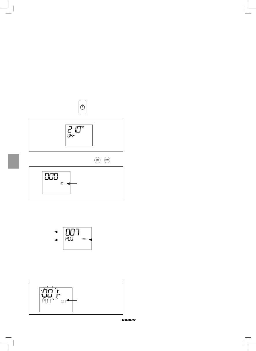
PROCEDURA DI CONFIGURAZIONE
PARAMETRI
■ Mettere in OFF il termostato
■ Premere contemporaneamente i tasti
Indicazione livello:
1= inserimento password
■Utilizzare i tasti  per modificare il valore del display
fino al valore di password 10, quindi premere  . Se corretta si avrà accesso ai parametri
|
|
|
|
|
|
|
|
|
Valore parametro |
|
|
||
|
|
selezionato |
|
|
|
Indicazione livello: |
|
|
|
|
|||
|
|
|
|
|
|
|
|
|
Parametro |
|
|
|
001= inserimento |
|
|
|
|
|
password |
|
|
|
selezionato: P... |
|
|||
|
|
|
|
|||
|
|
|
|
|
|
|
|
|
|
|
|
|
|
■Utilizzare i tasti  per scorrere i vari parametri (vedi “Lista Parametri” sopra descritta).
■Premere  per attivare la modifica del parametro (il valore comincerà a lampeggiare).
Indicazione livello:
003 = inserimento password
■utilizzare i tasti  per modificare il valore
■Premere  per salvare il nuovo valore impostato o
  per annullare la modifica
■Una volta conclusa la modifica di parametri interessati
premere il tasto  per uscire dalla procedura
NB La procedura di parametrizzazione ha una durata limitata. Una volta scaduto tale periodo (2 minuti circa) il termostato verrà riportato allo stato OFF mantenendo solo le modifiche salvate.
CONFIGURAZIONI PREVISTE (PARAMETRO P00)
Il comando LCD può essere configurato in diversi modi in base al tipo di sistema. Le varie configurazioni si ottengono configurando opportunamente il parametro P00 (vedi procedura di configurazione parametri comando).
001
■Tubi impianto: 2
■Valvola: NO
■Resistenza: NO
■Velocità ventilazione: 3
■Logica commutazione estate/inverno: LOCALE MANUALE
002
■Tubi impianto: 2
■Valvola: NO
■Resistenza: NO
■Velocità ventilazione: 3
■Logica commutazione estate/inverno: DISTANZA MANUALE
003
■Tubi impianto: 2
■Valvola: NO
■Resistenza: NO
■Velocità ventilazione: 3
■Logica commutazione estate/inverno: AUTOMATICA LATO
ACQUA
004
■Tubi impianto: 2
■Valvola: NO
■Resistenza: NO
■Velocità ventilazione: 4
■Logica commutazione estate/inverno: LOCALE MANUALE
005
■Tubi impianto: 2
■Valvola: NO
■Resistenza: NO
■Velocità ventilazione: 4
■Logica commutazione estate/inverno: DISTANZA MANUALE
006
■Tubi impianto: 2
■Valvola: NO
■Resistenza: NO
■Velocità ventilazione: 4
■Logica commutazione estate/inverno: AUTOMATICA LATO
ACQUA
Manuale d'installazione e d'uso |
FWEC1 |
2 |
Standard electronic controller |
FC66002763 |
CONFIGURAZIONI PREVISTE (PARAMETRO P00)
007
■Tubi impianto: 2
■Valvola: NO
■Resistenza: SI
■Velocità ventilazione: 3
■Logica commutazione estate/inverno: LOCALE MANUALE
008
■Tubi impianto: 2
■Valvola: NO
■Resistenza: SI
■Velocità ventilazione: 3
■Logica commutazione estate/inverno: DISTANZA MANUALE
009
■Tubi impianto: 2
■Valvola: NO
■Resistenza: si
■Velocità ventilazione: 3
■Logica commutazione estate/inverno: AUTOMATICA LATO
ARIA
010
■Tubi impianto: 2
■Valvola: 2/3 VIE
■Resistenza: NO
■Velocità ventilazione: 3
■Logica commutazione estate/inverno: LOCALE MANUALE
011
■Tubi impianto: 2
■Valvola: 2/3 VIE
■Resistenza: NO
■Velocità ventilazione: 3
■Logica commutazione estate/inverno: DISTANZA MANUALE
012
■Tubi impianto: 2
■Valvola: 2/3 VIE
■Resistenza: NO
■Velocità ventilazione: 3
■Logica commutazione estate/inverno: AUTOMATICA LATO
ACQUA
013
■Tubi impianto: 2
■Valvola: 2/3 VIE
■Resistenza: NO
■Velocità ventilazione: 4
■Logica commutazione estate/inverno: LOCALE MANUALE
014
■Tubi impianto: 2
■Valvola: 2/3 VIE
■Resistenza: NO
■Velocità ventilazione: 4
■Logica commutazione estate/inverno: DISTANZA MANUALE
015
■Tubi impianto: 2
■Valvola: 2/3 VIE
■Resistenza: NO
■Velocità ventilazione: 4
■Logica commutazione estate/inverno: AUTOMATICA LATO
ACQUA
016
■Tubi impianto: 2
■Valvola: 3 VIE
■Resistenza: SI
■Velocità ventilazione: 3
■Logica commutazione estate/inverno: LOCALE MANUALE
017
■Tubi impianto: 2
■Valvola: 3 VIE
■Resistenza: SI
■Velocità ventilazione: 3
■Logica commutazione estate/inverno: DISTANZA MANUALE
018
■Tubi impianto: 2
■Valvola: 3 VIE
■Resistenza: SI
■Velocità ventilazione: 3
■Logica commutazione estate/inverno: AUTOMATICA LATO
ARIA
019
■Tubi impianto: 4
■Valvola: NO
■Resistenza: NO
■Velocità ventilazione: 3
■Logica commutazione estate/inverno: LOCALE MANUALE
020
■Tubi impianto: 4
■Valvola: NO
■Resistenza: NO
■Velocità ventilazione: 3
■Logica commutazione estate/inverno: DISTANZA MANUALE
021
■Tubi impianto: 4
■Valvola: NO
■Resistenza: NO
■Velocità ventilazione: 3
■Logica commutazione estate/inverno: AUTOMATICA LATO
ARIA
022
■Tubi impianto: 4
■Valvola: NO
■Resistenza: NO
■Velocità ventilazione: 4
■Logica commutazione estate/inverno: LOCALE MANUALE
023
■Tubi impianto: 4
■Valvola: NO
■Resistenza: NO
■Velocità ventilazione: 4
■Logica commutazione estate/inverno: DISTANZA MANUALE
024
■Tubi impianto: 4
■Valvola: NO
■Resistenza: NO
■Velocità ventilazione: 4
■Logica commutazione estate/inverno: AUTOMATICA LATO
ARIA
FWEC1 |
Manuale d'installazione e d'uso |
Standard electronic controller |
3 |
FC66002763 |
CONFIGURAZIONI PREVISTE (PARAMETRO P00)
025
■Tubi impianto: 4
■Valvola: 2/3 VIE
■Resistenza: NO
■Velocità ventilazione: 3
■Logica commutazione estate/inverno: LOCALE MANUALE
026
■Tubi impianto: 4
■Valvola: 2/3 VIE
■Resistenza: NO
■Velocità ventilazione: 3
■Logica commutazione estate/inverno: DISTANZA MANUALE
027
■Tubi impianto: 4
■Valvola: 2/3 VIE
■Resistenza: NO
■Velocità ventilazione: 3
■Logica commutazione estate/inverno: AUTOMATICA LATO
ARIA
028
■Tubi impianto: 4
■Valvola: 2/3 VIE
■Resistenza: NO
■Velocità ventilazione: 3 + CN (CONVEZIONE NATURALE)
■Logica commutazione estate/inverno: LOCALE MANUALE
029
■Tubi impianto: 4
■Valvola: 2/3 vie
■Resistenza: NO
■Velocità ventilazione: 3 + CN (CONVEZIONE NATURALE)
■Logica commutazione estate/inverno: DISTANZA MANUALE
030
■Tubi impianto: 4
■Valvola: 2/3 VIE
■Resistenza: NO
■Velocità ventilazione: 3 + CN (CONVEZIONE NATURALE)
■Logica commutazione estate/inverno: AUTOMATICA LATO
ARIA
031
■Tubi impianto: 4
■Valvola: NO
■Resistenza: SI
■Velocità ventilazione: 3
■Logica commutazione estate/inverno: LOCALE MANUALE
LOGICHE
COMMUTAZIONE RAFFREDDAMENTO/RISCALDAMENTO
Sono presenti 4 differenti logiche di selezione della modalità di funzionamento del termostato definite in base alla configurazione impostata sul comando:
■Locale manuale: scelta dall’utente agendo sul tasto
■Distanza manuale: in funzione dello stato dell’Ingresso Digitale 1 (logica contatto: vedi parametri configurazione scheda)
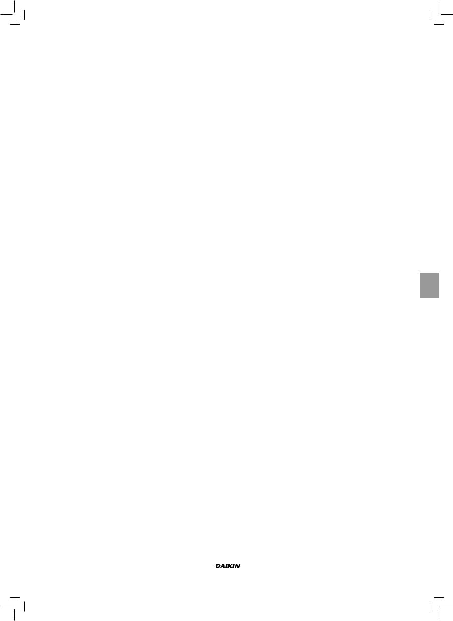
■Automatico in funzione della temperatura dell’acqua
Estate
Inverno
Temp. acqua
NB: nel caso di allarme sonda acqua il controllo della modalità torna temporaneamente nella modalità Locale
■ Automatico in funzione della temperatura dell’aria:
Estate
Inverno
Temp. aria
Dove:
-Set è la temperatura impostata con le frecce
-ZN è la zona neutra (parametro P03)
La modalità di funzionamento del termostato è indicata
sul display dai simboli |
(raffreddamento) e |
(riscaldamento). |
|
|
|
|
|
|
|
|
|
|
|
|
|
|
|
|
|
|
|
|
|
|
|
|
|
|
|
|
|
|
|
|
|
|
|
|
|
|
|
|
|
|
|
|
|
|
|
|
|
|
|
|
|
|
|
|
|
|
|
|
|
|
|
|
|
|
|
|
|
|
|
|
|
|
|
|
|
|
|
|
Manuale d'installazione e d'uso |
FWEC1 |
|
|
|
|
|
|
|
4 |
Standard electronic controller |
|
|
|
|
|
|
|
FC66002763 |
|
|
|
|
|
|
|
|
|
|
|
|
|
|
|
|
|
|
|
|
|
|
|
|
|
|
|
|
|
|
|
|
|
|
|
|
|
|
|
|
|
|
|
|
|
|
|
|
|
|
|
|
|
|
|
VENTILAZIONE
Il controllo può gestire terminali a 3 o 4 velocità di ventilazione
SELEZIONE VELOCITÀ FUNZIONAMENTO
Utilizzando il tasto Fan  è possibile scegliere fra le seguenti velocità:
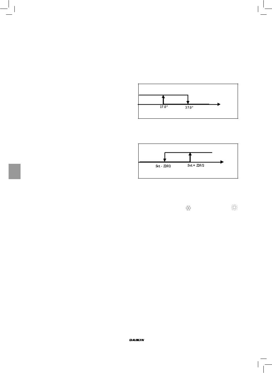
■AUTO Vel. automatica: in funzione della temperatura impostata e quella dell’aria ambiente.
Con configurazioni a 3 velocità: dove:
1 = velocità minima
2 = velocità media
3 = velocità massima
RAFFREDDAMENTO
Temp. aria
RISCALDAMENTO
Temp. aria
Con Configurazioni a 4 velocità: dove:
sm = velocità superminima 1 = velocità minima
2 = velocità media
3 = velocità massima
RAFFREDDAMENTO
Temp. aria
RISCALDAMENTO
Temp. aria
NB: nelle configurazioni con 4 velocità e valvola o 3 velocità + CN (convezione naturale), la ventilazione in riscaldamento viene ritardata di 0.5°C per consentire una prima fase di convezione naturale
■NESSUN SIMBOLO: Vel. disattivata. Selezionabile solo in riscaldamento e con configurazioni a 4 velocità o 3 velocità + CN (convezione naturale), fa funzionare il terminale in sola convezione naturale
■ Vel. superminima. Selezionabile solo con configurazioni a 4 velocità, utilizza come velocità fissa la superminima
Vel. minima
Vel. media
Vel. massima
NB Nel caso di velocità fissa la logica di attivazione del ventilatore sarà pari a quella della logica automatica.
CONSENSO DELL’ACQUA
Il funzionamento della ventilazione è vincolato al controllo della temperatura acqua dell’impianto. In base alla modalità di lavoro avremo differenti soglie di consenso in riscaldamento e raffreddamento.
RAFFREDDAMENTO
Temp. acqua
RISCALDAMENTO
Temp. acqua
L’assenza di tale consenso, alla chiamata del termostato, verrà indicata sul display con il lampeggio del simbolo della
modalità attiva (  o
o  )
)
Tale consenso viene ignorato in caso di:
■Sonda acqua non prevista (P04 = 0) o in allarme perché scollegata.
■In Raffreddamento con configurazioni a 4 tubi.
FORZATURE
La normale logica di ventilazione verrà ignorata nel caso di particolari situazioni di forzatura che possono essere necessarie per il corretto controllo della temperatura o funzionamento del terminale. Si possono avere:
in Raffreddamento:
■con comando a bordo macchina (P01 = 0) e configurazioni con valvola: viene mantenuta la minima velocità disponibile anche a temperatura raggiunta.
■Comando a bordo e configurazioni senza valvola: ogni 10 minuti di ventilatore fermo viene eseguito un lavaggio di 2 minuti alla velocità media per permettere alla sonda aria una lettura più corretta della temperatura ambiente.
In Riscaldamento
■Con resistenza attiva: viene forzata la ventilazione alla velocità media.
■Una volta spenta la resistenza: viene mantenuta, per 2 minuti, una post ventilazione alla velocità media. (NB: tale ventilazione verrà completata anche se il termostato dovesse venir spento o si passasse alla modalità raffreddamento).
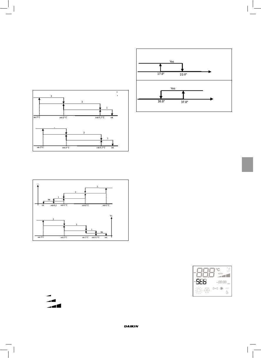
DISPLAY
Il display visualizza lo stato del ventilatore
■Stb: ventilatore in standby
■On: ventilatore acceso
■noF: ventilatore disattivato per lavorare in sola convezione naturale
FWEC1 |
Manuale d'installazione e d'uso |
Standard electronic controller |
5 |
FC66002763 |
Il display visualizza la velocità di funzionamento (con eventuale indicazione della logica “automatica”) attiva o selezionata (nel caso di ventilatore in stand-by)
Vel. superminima
Vel. minima
Vel. media
 Vel. massima
NB: nel caso la velocità attiva sia diversa da quella selezionata da utente (in caso di forzatura..), una prima pressione
del tasto  visualizzerà quest’ultima; una pressione successiva cambierà tale impostazione.
VALVOLA
Il controllo può gestire valvole a 2 o 3 vie di tipo ON/OFF con tensione di alimentazione dell'attuatore di 230 V.
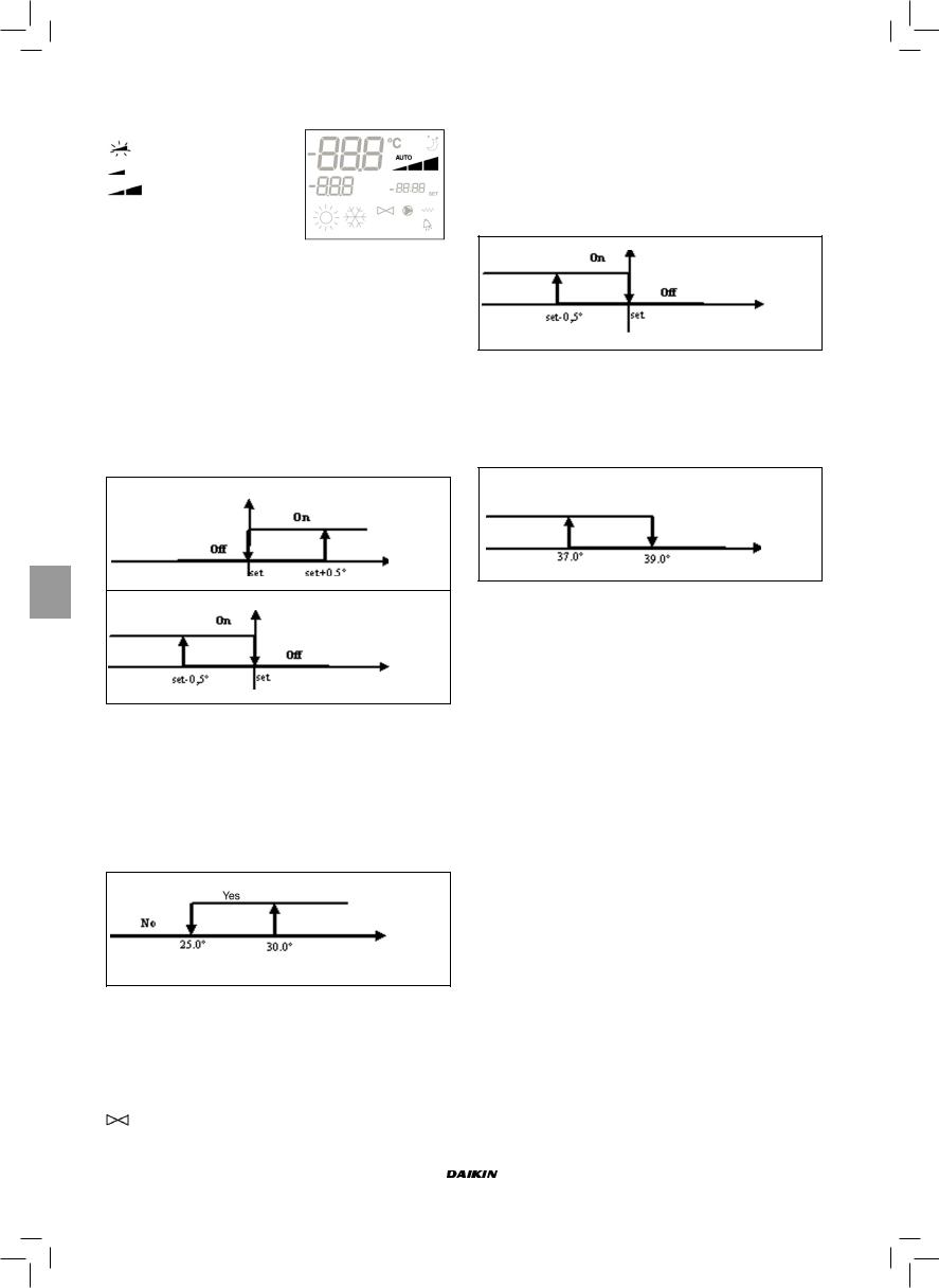
APERTURA
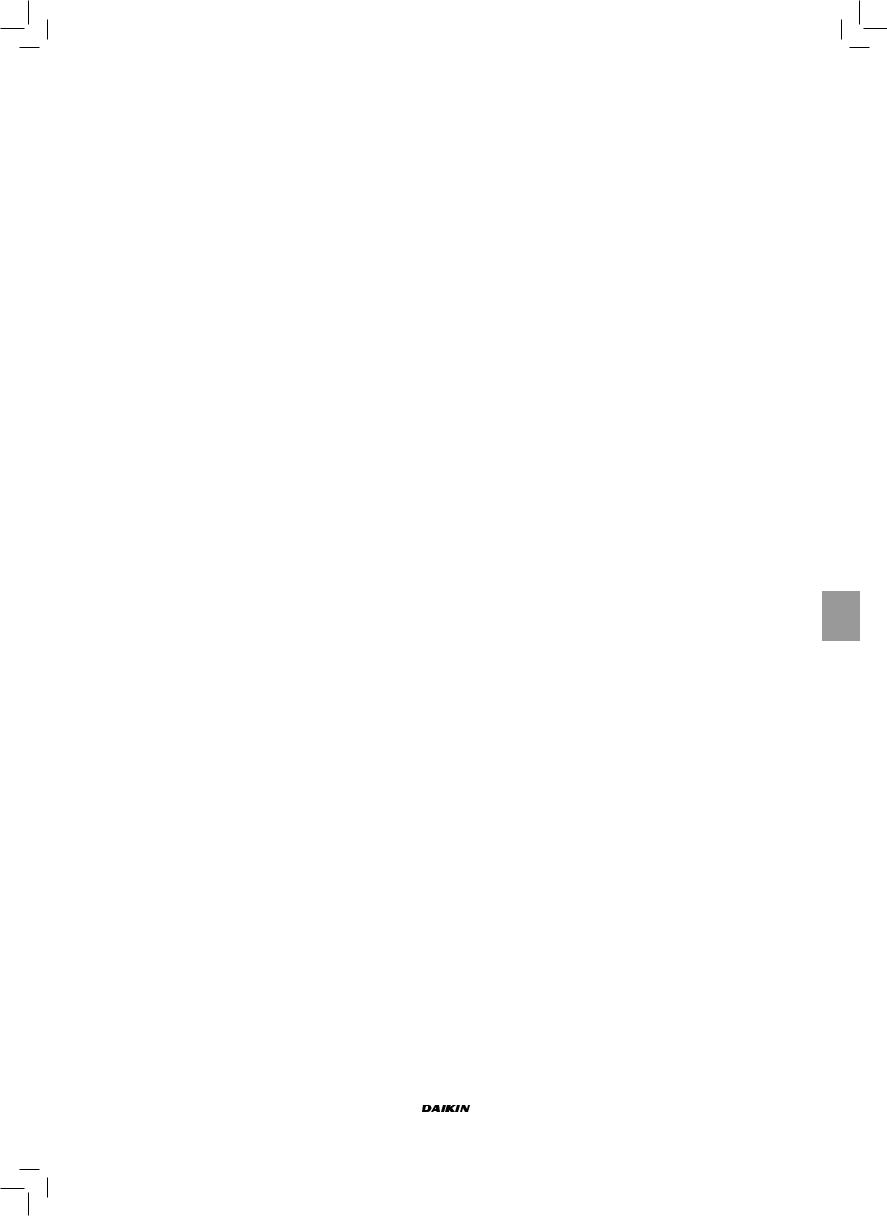
L’apertura della valvola viene comandata in funzione del set di lavoro e della temperatura dell’aria
RAFFREDDAMENTO
Temp. aria
RISCALDAMENTO
Temp. aria
CONSENSO DELL’ACQUA
Il controllo della temperatura dell’acqua per il consenso all’apertura interessa solo configurazioni con valvole a 3 e resistenza elettrica. In tali configurazioni verrà fatto un controllo della temperatura dell’acqua in caso di:
■Riscaldamento con resistenza: il funzionamento della resistenza comporta una forzatura della ventilazione; è necessario quindi evitare l’eventuale passaggio di acqua troppo fredda nel terminale.
Temp. acqua
■Post ventilazione dovuta allo spegnimento resistenza: mantenuta fino allo scadere del tempo stabilito, anche nel caso di cambio della modalità di funzionamento, durante tale post ventilazione il consenso dell’acqua coinciderà con quello visto per la ventilazione.
DISPLAY
L’indicazione di valvola attiva sul display sarà data dal simbolo
RESISTENZA ELETTRICA
La resistenza elettrica è un dispositivo gestito come eventuale supporto nella fase di riscaldamento.
SELEZIONE
Se prevista dalla configurazione la resistenza può essere selezionata in riscaldamento tramite il tasto Sel  .
.
ATTIVAZIONE
Temp. aria
L’utilizzo della resistenza elettrica, se selezionata da utente, viene utilizzata su chiamata del termostato in base alla temperatura ambiente
NB: l’attivazione comporta una forzatura della ventilazione
CONSENSO DELL’ACQUA
RISCALDAMENTO
ON
OFF
Temp. acqua
Il consenso per l’attivazione della resistenza è legato al controllo della temperatura dell’acqua. Di seguito la logica di consenso relativa
Tale consenso non verrà dato nel caso di sonda dell’acqua non prevista o scollegata
DISPLAY
Il display visualizzerà le seguenti informazioni
■resistenza selezionata da utente: simbolo  fisso
fisso
■resistenza attiva: simbolo  lampeggiante
Manuale d'installazione e d'uso |
FWEC1 |
6 |
Standard electronic controller |
FC66002763 |
ECONOMY
La funzione Economy prevede una correzione del setpoint di 2.5°C e una forzatura alla minima velocità disponibile per ridurre il funzionamento del terminale.
■Raffreddamento: set + 2.5°C
■Riscaldamento: set – 2.5°C
ATTIVAZIONE
La funzione è attivabile con la pressione del tasto 
DISPLAY
Sul display la funzione Economy
è indicata da simbolo
CONTROLLO MINIMA TEMPERATURA
Tale logica permette di controllare, con termostato spento, che la temperatura ambiente non scenda troppo, forzando eventualmente il terminale in modalità riscaldamento per il tempo necessario.
Se presente la resistenza elettrica essa verrà utilizzata solo nel caso in cui fosse stata precedentemente selezionata come risorsa in Riscaldamento.
SELEZIONE
Il controllo Minima Temperatura è selezionabile, a termostato
spento, con la pressione contemporanea dei tasti 
 . La stessa combinazione di tasti disattiva tale funzionamento
ATTIVAZIONE
Se tale controllo è selezionato, il terminale si accenderà nel caso in cui la temperatura ambiente scenda al di sotto dei 9°C.
Temp. aria
Una volta riportata la temperatura sopra i 10°C il termostato ritornerà nella situazione di OFF.
NB: un eventuale OFF da ingresso digitale inibirà tale logica.
DISPLAY
Il display visualizza le seguenti informazioni
■controllo Minima Temperatura selezionato: simbolo 
■controllo Minima Temperatura attivo: indicazione DEFR
ALLARMI
Il comando gestisce due tipologie di allarmi:
■Allarmi Gravi: causano lo spegnimento forzato del termostato
■Allarmi Non Gravi: non forzano lo spegnimento del termostato ma inibiscono eventuali funzionalità critiche
ALLARMI GRAVI
■Cod. 01= errore sonda esterna di temperatura dell’aria (se termostato installato a Bordo)
■Cod. 02 = errore sonda interna di temperatura dell’aria (se termostato installato a Parete e sonda esterna di temperatura dell’aria sconnessa)
ALLARMI NON GRAVI
Termostato OFF |
Termostato ON |
■ Cod. 03 = errore sonda di temperatura dell’acqua
NB: l’indicazione del codice allarme è visualizzato solo con termostato spento.
PROCEDURA DI AUTODIAGNOSI
Tale procedura permette di verificare il corretto funzionamento delle singole uscite del comando stesso.
Per eseguire tale procedura seguire le indicazioni sotto riportate.
■ Mettere in Off il termostato
■ Premere contemporaneamente i tasti 
Indicazione livello:
1= inserimento password
■Utilizzare i tasti  per modificare il valore del display fino al valore di password per la autodiagnosi (030) e premere
  . Verrà visualizzata la seguente schermata:
■Premere il tasto  per accendere in successione le varie uscite del termostato.
FWEC1 |
Manuale d'installazione e d'uso |
Standard electronic controller |
7 |
FC66002763 |

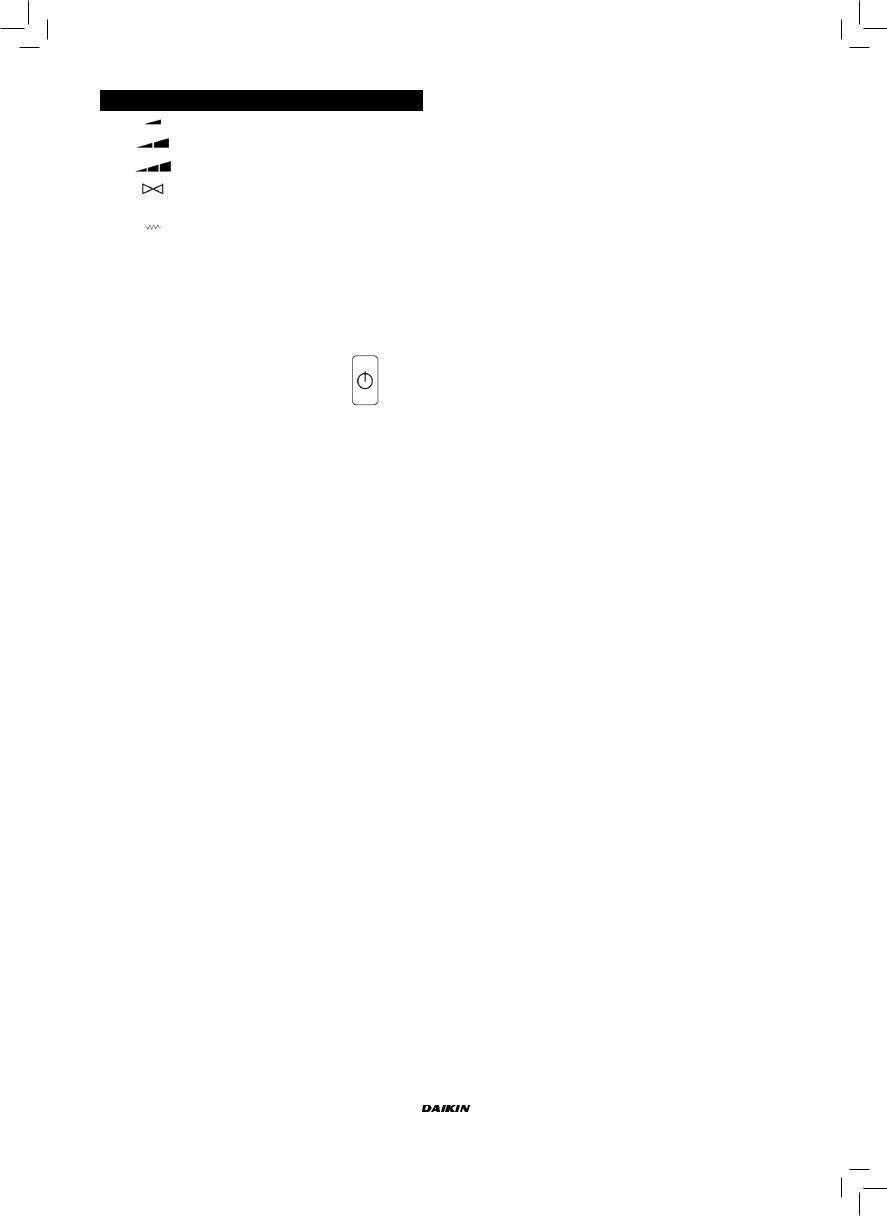
Simbolo |
Azionamento |
Morsetti |
|
Velocità minima |
N-V1 |
|
|
|
|
Velocità media |
N-V2 |
|
|
|
|
Velocità massima |
N-V3 |
|
|
|
|
Valvola |
N-Vc |
|
|
|
|
Resistenza |
|
|
Seconda valvola |
N-Vh |
|
Vel. superminima |
|
|
|
|
nessun simbolo |
nessuna uscita attiva |
|
|
|
|
È possibile verificare, una ad una, le uscite del controllo elettronico osservando il relativo componente (valvola, ventilatore..) o verificando la presenza di una tensione di 230V ai morsetti corrispondenti.
■ Premere il tasto per uscire dalla procedura di autodiagnosi (Dopo alcuni minuti il termostato uscirà automaticamente comunque).
SCHEDA ELETTRONICA (VEDI FIGURA 3)
Dove
CI12 |
Comune DI1-2 |
|
|
DI1 |
Raffred./ Riscaldam remoto |
|
|
DI2 |
On/ Off remoto |
|
|
L |
Fase |
|
|
N |
Neutro |
|
|
PE |
Terra |
|
|
SA |
Sonda aria remota |
|
|
SW |
Sonda acqua |
|
|
V0 |
- |
|
|
V1 |
Vel. minima |
|
|
V2 |
Vel. media |
|
|
V3 |
Vel. massima |
|
|
Vc |
Valvola |
|
|
Vh |
Valvola Caldo / Resistenza / Vel.superminima |
|
|
NB
■Per collegamenti di potenza utilizzare cavo sezione 1 mm2
■Per ingressi digitali utilizzare cavo tipo AWG 24
■Per prolungamenti sonde utilizzare cavo schermato tipo AWG 24
|
|
|
|
|
|
|
|
|
|
|
|
|
|
|
|
Manuale d'installazione e d'uso |
FWEC1 |
|
|
|
|
|
|
|
8 |
Standard electronic controller |
|
|
|
|
|
|
|
FC66002763 |
|
|
|
|
|
|
|
|
|
|
|
|
|
|
|
|
|
|
|
|
|
|
|
|
|
|
|
|
|
|
|
|
|
|
|
|
|
|
|
|
|
|
|
|
|
|
|
|
|
|
|
|
|
|
|

SCHEMI ELETTRICI
(Vedi allegato Schemi Elettrici)
Tabella Configurazioni/Schemi
CONFIG. |
UNITA’ |
SCHEMA |
|
|
|
|
|
||
|
FWL-M-V |
FC66002487 [1] |
||
|
|
|
||
01-02-03 |
FWB |
UT66000879 [4] |
||
|
|
|
||
FWD |
UT66000880 [5] |
|||
|
||||
|
|
|
||
|
UT66000881 [6] |
|||
|
|
|||
|
|
|
||
|
FWL-M-V |
FC66002491 [2] |
||
|
|
|
||
|
FWB |
UT66000882 [7] |
||
|
|
|
||
07-08-09 |
|
UT66000883 [8] |
||
|
|
|
||
FWD |
UT66000884 [9] |
|||
|
||||
|
|
|
||
|
UT66000885 |
[10] |
||
|
|
|||
|
|
|
|
|
|
|
UT66000886 |
[11] |
|
|
|
|
||
|
FWL-M-V |
FC66002487 [1] |
||
|
|
|
||
10-11-12 |
FWB |
UT66000879 [4] |
||
|
|
|
||
FWD |
UT66000880 [5] |
|||
|
||||
|
|
|
||
|
UT66000881 [6] |
|||
|
|
|||
|
|
|
||
|
FWL-M-V |
FC66002491 [2] |
||
|
|
|
||
|
FWB |
UT66000882 [7] |
||
|
|
|
||
16-17-18 |
|
UT66000883 [8] |
||
|
|
|
||
FWD |
UT66000884 [9] |
|||
|
||||
|
|
|
||
|
UT66000885 |
[10] |
||
|
|
|||
|
|
|
|
|
|
|
UT66000886 |
[11] |
|
|
|
|
||
|
FWL-M-V |
FC66002487 [1] |
||
|
|
|
||
19-20-21 |
FWB |
UT66000879 [4] |
||
|
|
|
||
FWD |
UT66000880 [5] |
|||
|
||||
|
|
|
||
|
UT66000881 [6] |
|||
|
|
|||
|
|
|
||
|
FWL-M-V |
FC66002487 [1] |
||
|
|
|
||
25-26-27 |
FWB |
UT66000879 [4] |
||
|
|
|
||
FWD |
UT66000880 [5] |
|||
|
||||
|
|
|
||
|
UT66000881 [6] |
|||
|
|
|||
|
|
|
||
|
FWB |
UT66000882 [7] |
||
|
|
|
||
|
|
UT66000883 [8] |
||
|
|
|
||
31 |
FWD |
UT66000884 [9] |
||
|
|
|
||
|
UT66000885 |
[10] |
||
|
|
|||
|
|
|
|
|
|
|
UT66000886 |
[11] |
|
|
|
|
|
|
Tabella Unità/Schemi
UNITA’ |
TIPO |
CONFIGURAZIONE |
SCHEMA |
|
|
|
|
|
|
|
|
|
|
FWL-M-V |
- |
1-2-3-10-11-12-19-20-21-25-26-27 |
FC66002487 |
|
|
|
|
|
|
|
|
|
|
|
7-8-9-16-17-18 |
FC66002491 |
|
|
|
|
|
|
|
|
|||
|
|
|
|
|
|
|
FWB |
- |
1-2-3-10-11-12-19-20-21-25-26-27 |
UT66000879 |
|
|
|
|
|
|
|
|
|
|
|
7-8-9-16-17-18-31 |
UT66000882 |
|
|
|
|
|
|
|
|
|||
|
|
|
|
|
|
|
|
04/12 |
1-2-3-10-11-12-19-20-21-25-26-27 |
UT66000881 |
|
|
|
|
|
|
|
|
|
|
|
|
7-8-9-16-17-18-31 |
UT66000884 |
|
|
|
|
|
|
|
|
|
|
FWD |
06/12 3PH |
7-8-9-16-17-18-31 |
UT66000886 |
|
|
|
|
|
|
|
|
|
|
16/18 |
1-2-3-10-11-12-19-20-21-25-26-27 |
UT66000880 |
|
|
|
|
|
|
|
||||
|
|
|
|
|
|
|
|
|
7-8-9-16-17-18-31 |
UT66000883 |
|
|
|
|
|
|
|
|
|
|
|
16/18 3PH |
7-8-9-16-17-18-31 |
UT66000885 |
|
|
|
|
|
|
|
|
|
|
|
FWL-M-V |
- |
|
|
|
|
|
|
|
|
|
|
|
EPIMSB6 |
FWB |
- |
FC66002493 |
|
|
|
|
|
|
|
|
|
|
|
FWD |
- |
|
|
|
|
|
|
|
|
|
|
|
|
|
|
|
|
|
|
|
|
|
|
|
|
|
|
|
|
|
|
|
|
|
|
|
|
|
|
|
FWEC1 |
Manuale d'installazione e d'uso |
Standard electronic controller |
9 |
FC66002763 |

SCHEMI ELETTRICI
Tabella Unità/Schemi
|
|
|
….. |
Collegamenti elettrici a cura dell’installatore |
|
|
|
|
|
|
|
|
BU |
Blu (Vel. Media) |
|
|
|
|
|
|
|
|
BK |
Nero (Vel. Massima) |
|
|
|
|
|
|
|
|
BN |
Marrone |
|
|
|
|
|
|
|
|
CI12 |
Comune ingressi digitali |
|
|
|
|
|
|
|
|
CN |
Morsettiera Terminale |
|
|
|
|
|
|
|
|
DI1 |
Ingresso digitale Raffr./Risc remoto |
|
|
|
|
|
|
|
|
DI2 |
Ingresso digitale On/Off remoto |
|
|
|
|
|
|
|
|
EXT |
Contatto ausiliario esterno |
|
|
|
|
|
|
|
|
F |
Fusibile (non fornito) |
|
|
|
|
|
|
|
|
GN |
Verde |
|
|
|
|
|
|
|
|
GY |
Grigio |
|
|
|
|
|
|
|
|
IL |
Interruttore di linea (non fornito) |
|
|
|
|
|
|
|
|
EPIB6 |
Scheda di potenza per unità tipo FWD |
|
|
|
|
|
|
|
|
EPIMSB6 |
Scheda di potenza per gestire 4 terminali |
|
|
|
|
|
|
|
|
L |
Fase |
|
|
|
|
|
|
|
|
M |
Motore Ventilatore |
|
||||
|
|
|
|
|
|
|
|
N |
Neutro |
|
|
|
|
|
|
|
|
PE |
Terra |
|
||||
|
|
|||
|
|
|
|
|
|
|
|
RHC |
Selettore remoto Riscald./Raffredd. |
|
|
|
|
|
|
|
|
RE |
Resistenza Elettrica |
|
|
|
|
|
|
|
|
RD |
Rosso (Vel. Minima) |
|
|
|
|
|
|
|
|
SA |
Sonda Aria |
|
|
|
|
|
|
|
|
SC |
Scatola cablaggi |
|
|
|
|
|
|
|
|
SW |
Sonda Acqua |
|
|
|
|
|
|
|
|
TSA |
Termostato di sicurezza automatico |
|
|
|
|
|
|
|
|
TSM |
Termofusibile di sicurezza |
|
|
|
|
|
|
|
|
V1 |
Velocità Minima |
|
|
|
|
|
|
|
|
V2 |
Velocità Media |
|
|
|
|
|
|
|
|
V3 |
Velocità Massima |
|
|
|
|
|
|
|
|
VC |
Valvola solenoide Raffreddamento |
|
|
|
|
|
|
|
|
VH |
Valvola solenoide Riscaldamento |
|
|
|
|
|
|
|
|
VHC |
Valvola solenoide Raffr./Risc. |
|
|
|
|
|
|
|
|
WH |
Bianco (comune) |
|
|
|
|
|
|
|
|
YE |
Giallo |
|
|
|
|
|
|
|
|
KR |
Relè per resistenza elettrica |
|
|
|
|
|
|
|
|
|
|
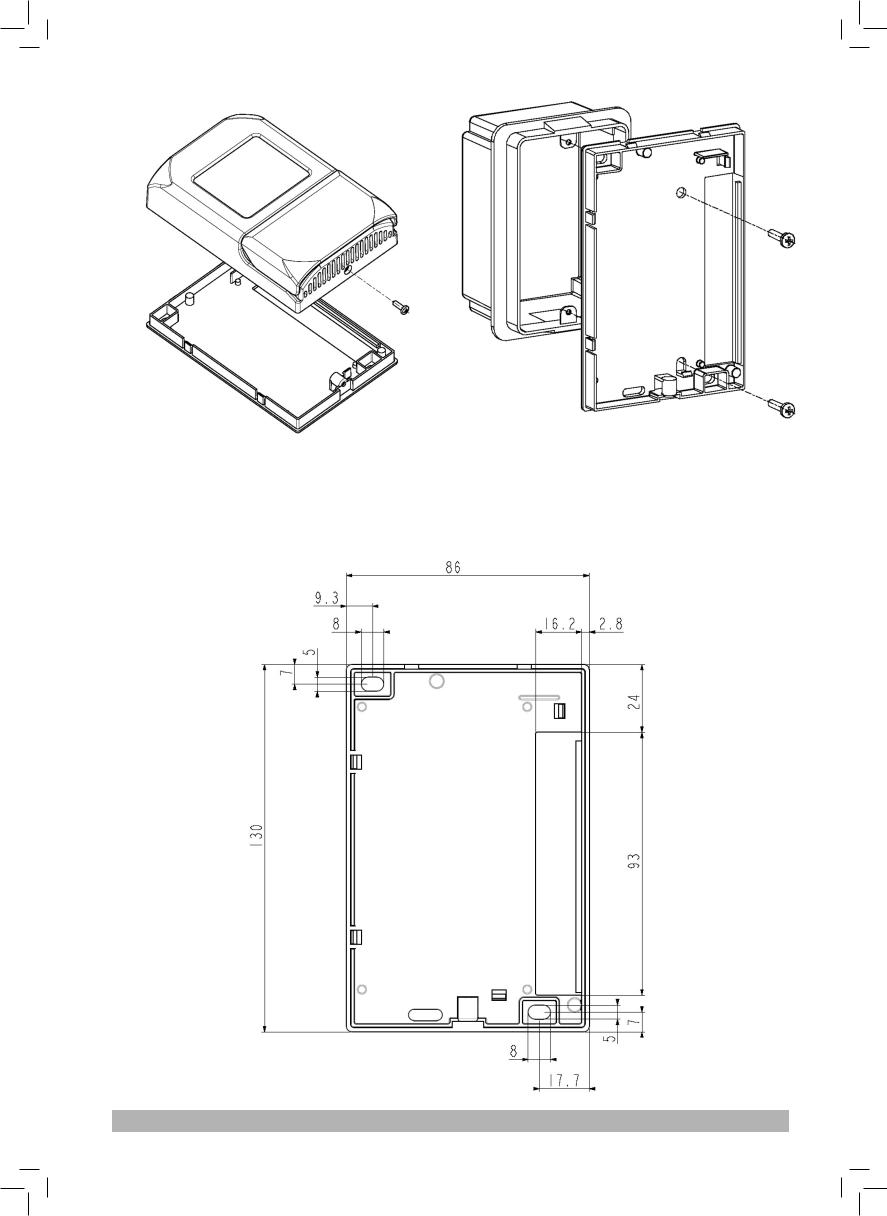
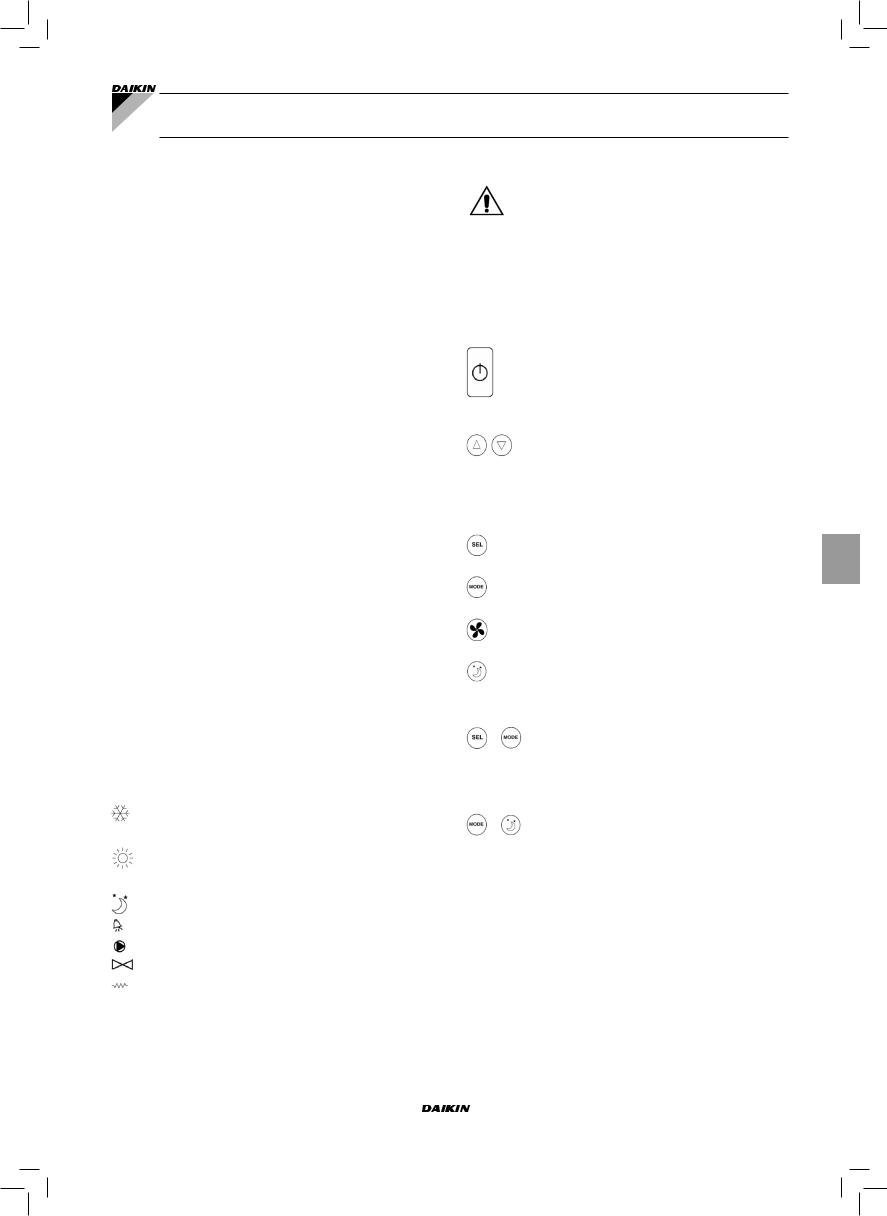
INSTALLAZIONE COMANDO A PARETE
Per l'installazione del comando a parete è consigliabile l'ìutilizzo di una scatola elettrica, dietro al comando, per l'alloggiamento dei cavi.
NB: prima dell'installazione rimuovere, con cautela, la pellicola protettiva del display; la rimozione della pellicola può provocare la comparsa di aloni scuri sul display che scompaiono dopo alcuni secondi e non sono indice di difettosità del comando.
Istruzioni per il montaggio
■Togliere la vite di chiusura del comando (vedere figura 4)
■In caso di utilizzo di una scatola portafrutti 503, passare i cavi attraverso la feritoia alla base del comando ed utilizzare per il fissaggio gli appositi fori. (vedere figura 5).
■Altrimenti forare la parete dove si vuole installare il comando, in corrispondenza delle asole di fissaggio (5x8mm) poste nella base del comando; passare i cavi attraverso la feritoia della base e fissarla con delle viti alla parete (precedentemente forata). (vedere figura 6).
■Eseguire i collegamenti elettrici sulla morsettiera del terninale seguendo lo schema relativo.
■Richiudere il comando con l'apposita vite.
DATI TECNICI
|
90-250Vac 50/60Hz |
|
|
|
|
Alimentazione |
Potenza 8W |
|
|
|
|
|
Fusibile di protezione: 500mA ritardato |
|
|
|
|
Temp. Funzionamento |
Range 0-50°C |
|
|
|
|
Temp. Stoccaggio |
Range -10-60°C |
|
|
|
|
|
Normal Open 5A @ 240V (Resistivo) |
|
|
|
|
Relè |
Isolamento: distanza bobina-contatti 8mm |
|
|
||
4000V dielettrico bobina-relè |
||
|
||
|
|
|
|
Temperatura ambiente max.: 105°C |
|
|
|
|
Connettori |
250V 10A |
|
|
|
|
|
Contatto pulito |
|
|
|
|
Ingressi digitali |
Corrente di chiusura 2mA |
|
|
|
|
|
Max resistenza di chiusura 50 Ohm |
|
|
|
|
Ingressi analogici |
Sonde di Temperatura |
|
|
|
|
Uscite di potenza |
Relè (vedi sopra) |
|
|
|
|
Sonde di Temperatura |
Sonde NTC 10K Ohm @25°C |
|
|
||
Range -25-100°C |
||
|
||
|
|
Manuale d'installazione e d'uso |
FWEC1 |
10 |
Standard electronic controller |
FC66002763 |
FWEC1 |
Standard electronic controller |
Installation and operation manual
GENERAL CHARACTERISTICS
LCD controller has been designed to govern the operation of Daikin indoor units with single-phase multispeed
asynchronous motor.
MAIN FUNCTIONS AND FEATURES:
■Air temperature adjustment through automatic variation of fan speed;
■Regulation of air temperature via fan on-off control (fan runs at a fixed speed),
■Control of On-Off valves for two or four-pipe systems
■Control of heating element for auxiliary heating.
■Cooling/heating switching in the following modes:
-local manual switching
-remote, manual (centralised);
-automatic, depending on water temperature
-automatic, depending on air temperature
Additional features include:
■Digital input 1 – Clean contact for remote centralised switching of cooling/heating function (contact logic: see configuration parameters of board).
■Digital input 2 - Clean contacts for external activation (e.g. window contact, remote ON/OFF, occupancy sensor, etc.) which may enable or disable unit operation (contact logic: see configuration parameters of board)
■Remote water temperature sensor (FWTSK)
■Remote air sensor (FWTSK) (this sensor, if present, is used in place of the internal one for the measurement of room temperature).
The control panel is composed of:
■LCD display
■Keyboard
____________________________________________________________
The appliance is not to be used by children or person withreducedphysical,sensoryormentalcapabilities, orlackofexperienceandknowledge,unlesstheyhave been given supervision or instruction.
Children being supervised not to play with appliance
Keyboard (see figure 2)
____________________________________________________________
KEYBOARD (SEE FIGURE 2)
On/Off key: Thermostat On/Off. During the procedure of parameter modification, it permits to return to normal operating conditions
Up and Down keys: changing of thermostat setting temperature (Heating :[5.0-30.0°C], Cooling: [10.0-35.0°C]). During the procedure of parameter modification, they are used to select the parameters or to change their value
SEL key: in the heating mode, the electric heating element can be selected as auxiliary function
Mode key: selection of Heating/Cooling operating mode
Fan key: selection of operating speed
EC key: selection of Economy mode
LCD DISPLAY (SEE FIGURE 1)
(1)room temperature
(2)Thermostat / fan status
(3)Set temperature
AUTO Automatic ventilation logic  Fan speed
Operation mode: Cooling. When flashing it indicates that water circuit is not enabled to fan ventilation.
Operation mode: Heating. When flashing it indicates that water circuit is not enabled to fan ventilation.
Economy option enabled Alarm triggered
Minimum Temperature Control
Valve open
Heating element. If the symbol flashes it means that the heating element is on; if steadily lit it means only that the heating element has been selected
ACTIVE KEY COMBINATIONS
With OFF thermostat: access to the parameter configuration procedure
With ON thermostat: display of current water temperature
Selection of Minimum air temperature function
BOARD CONFIGURATION
The board can be configured according to the type of unit/ system to be governed by changing some parameters.
PARAMETER LIST
■P00= controller configuration (see “Available configurations”) to select the type of unit to be governed.
■P01 = type of controller installation
-000: on the unit
-001: wall mounted
■P02 = (not used)
■P03= neutral zone [20-50°C/10]; parameter used in case of configurations with automatic cooling/heating changeover according to air temperature.
|
|
|
|
|
|
|
|
|
|
|
|
|
|
|
|
|
|
FWEC1 |
Installation and operation manual |
|
|
|
|
|
|
|
Standard electronic controller |
1 |
|
|
|
|
|
|
|
FC66002763 |
|
|
|
|
|
|
|
|
|
|
|
|
|
|
|
|
|
|
|
|
|
|
|
|
|
|
|
|
|
|
|
|
|
|
|
|
|
|
|
|
|
|
|
|
|
|
|
|
|
|
|
|
|
|
|
|
|
|
|
|
|
|

■P04 = water sensor:
-000: not available
-001: available
Based on the set value, the sensor alarm and the heating element functions will be controlled
■P05 = use logic – Digital input 1 for Cooling/Heating switching:
-000: (open/closed) = (Cooling/Heating)
-001: (open/closed) = (Heating/Cooling)
■P06 = use logic – Digital input 2 for On/Off switching:
-000: (open/closed) = (On/Off)
-001: (open/closed) = (Off/On)
PARAMETER CONFIGURATION PROCEDURE
■ Switch the thermostat off
■ Push the keys at the same time
level indication: 1= password entry
■Use keys  to modify the display value up to the password value 10, and press
  .
.
If it is correct, you will have access to the parameters
|
|
Value of selected |
|||||
|
|
parameter |
|
|
|
|
level indication: |
|
|
|
|
|
|
||
|
|
|
|
|
|
|
|
|
|
Selected |
|
|
|
|
001= password |
|
|
|
|
|
|
entry |
|
|
|
parameter |
|
|
|
|
|
|
|
P... |
|||||
|
|
|
|
|
|
|
|
|
|
|
|
|
|
|
|
■Use keys  to scroll the various parameters (see “Parameter list” described above)
■Press  to confirm the parameter change (the value will start flashing).
level indication:
003= password entry
■use keys  to change the value
■Press  to save the new value setting or
  to cancel the modification
■After completing the modification of the parameters
concerned press key |
to exit the procedure |
NB The parameter configuration phase is of limited duration. Once a certain time has elapsed (around 2 minutes) the thermostat will switch back into the Off status and only the saved changes will be retained.
AVAILABLE CONFIGURATIONS (PARAMETER P00)
The LCD controller can be configured in various ways according to the type of system. Various configurations can be obtained through the P00 parameter (see configuration procedure of controller parameters).
001
■System pipes: 2
■Valve: NO
■Heating element: NO
■Fan speed: 3
■Summer/winter switching logic: LOCAL MANUAL
002
■System pipes: 2
■Valve: NO
■Heating element: NO
■Fan speed: 3
■Summer/winter switching logic: REMOTE MANUAL
003
■System pipes: 2
■Valve: NO
■Heating element: NO
■Fan speed: 3
■Summer/winter switching logic: AUTOMATIC WATER SIDE
004
■System pipes: 2
■Valve: NO
■Heating element: NO
■Fan speed: 4
■Summer/winter switching logic: LOCAL MANUAL
005
■System pipes: 2
■Valve: NO
■Heating element: NO
■Fan speed: 4
■Summer/winter switching logic: REMOTE MANUAL
006
■System pipes: 2
■Valve: NO
■Heating element: NO
■Fan speed: 4
■Summer/winter switching logic: AUTOMATIC WATER SIDE
|
|
|
|
|
|
|
|
|
|
|
|
|
|
|
|
|
|
|
|
|
|
|
|
|
Installation and operation manual |
FWEC1 |
|
|
|
|
|
|
|
2 |
Standard electronic controller |
|
|
|
|
|
|
|
FC66002763 |
|
|
|
|
|
|
|
|
|
|
|
|
|
|
|
|
|
|
|
|
|
|
|
|
|
|
|
|
|
|
|
|
|
|
|
|
|
|
|
|
|
|
|
|
|
|
|
|
|
|
|
|
|
|
|
AVAILABLE CONFIGURATIONS (PARAMETER P00)
007
■System pipes: 2
■Valve: NO
■Heating element: YES
■Fan speed: 3
■Summer/winter switching logic: LOCAL MANUAL
008
■System pipes: 2
■Valve: NO
■Heating element: YES
■Fan speed: 3
■Summer/winter switching logic: REMOTE MANUAL
009
■System pipes: 2
■Valve: NO
■Heating element: yes
■Fan speed: 3
■Summer/winter switching logic: AUTOMATIC AIR SIDE
010
■System pipes: 2
■Valve: 2-3 WAYS
■Heating element: NO
■Fan speed: 3
■Summer/winter switching logic: LOCAL MANUAL
011
■System pipes: 2
■Valve: 2-3 WAYS
■Heating element: NO
■Fan speed: 3
■Summer/winter switching logic: REMOTE MANUAL
012
■System pipes: 2
■Valve: 2-3 WAYS
■Heating element: NO
■Fan speed: 3
■Summer/winter switching logic: AUTOMATIC WATER SIDE
013
■System pipes: 2
■Valve: 2-3 WAYS
■Heating element: NO
■Fan speed: 4
■Summer/winter switching logic: LOCAL MANUAL
014
■System pipes: 2
■Valve: 2-3 WAYS
■Heating element: NO
■Fan speed: 4
■Summer/winter switching logic: REMOTE MANUAL
015
■System pipes: 2
■Valve: 2-3 WAYS
■Heating element: NO
■Fan speed: 4
■Summer/winter switching logic: AUTOMATIC WATER SIDE
016
■System pipes: 2
■Valve: 3 WAYS
■Heating element: YES
■Fan speed: 3
■Summer/winter switching logic: LOCAL MANUAL
017
■System pipes: 2
■Valve: 3 WAYS
■Heating element: YES
■Fan speed: 3
■Summer/winter switching logic: REMOTE MANUAL
018
■System pipes: 2
■Valve: 3 WAYS
■Heating element: YES
■Fan speed: 3
■Summer/winter switching logic: AUTOMATIC AIR SIDE
019
■System pipes: 4
■Valve: NO
■Heating element: NO
■Fan speed: 3
■Summer/winter switching logic: LOCAL MANUAL
020
■System pipes: 4
■Valve: NO
■Heating element: NO
■Fan speed: 3
■Summer/winter switching logic: REMOTE MANUAL
021
■System pipes: 4
■Valve: NO
■Heating element: NO
■Fan speed: 3
■Summer/winter switching logic: AUTOMATIC AIR SIDE
022
■System pipes: 4
■Valve: NO
■Heating element: NO
■Fan speed: 4
■Summer/winter switching logic: LOCAL MANUAL
023
■System pipes: 4
■Valve: NO
■Heating element: NO
■Fan speed: 4
■Summer/winter switching logic: REMOTE MANUAL
024
■System pipes: 4
■Valve: NO
■Heating element: NO
■Fan speed: 4
■Summer/winter switching logic: AUTOMATIC AIR SIDE
|
|
|
|
|
|
|
|
|
|
|
|
|
|
|
|
|
|
FWEC1 |
Installation and operation manual |
|
|
|
|
|
|
|
Standard electronic controller |
3 |
|
|
|
|
|
|
|
FC66002763 |
|
|
|
|
|
|
|
|
|
|
|
|
|
|
|
|
|
|
|
|
|
|
|
|
|
|
|
|
|
|
|
|
|
|
|
|
|
|
|
|
|
|
|
|
|
|
|
|
|
|
|
|
|
|
|
|
|
|
|
|
|
|

AVAILABLE CONFIGURATIONS (PARAMETER P00)
025
■System pipes: 4
■Valve: 2-3 WAYS
■Heating element: NO
■Fan speed: 3
■Summer/winter switching logic: LOCAL MANUAL
026
■System pipes: 4
■Valve: 2-3 WAYS
■Heating element: NO
■Fan speed: 3
■Summer/winter switching logic: REMOTE MANUAL
027
■System pipes: 4
■Valve: 2-3 WAYS
■Heating element: NO
■Fan speed: 3
■Summer/winter switching logic: AUTOMATIC AIR SIDE
028
■System pipes: 4
■Valve: 2-3 WAYS
■Heating element: NO
■Fan speed: 3 + CN (NATURAL CONVECTION)
■Summer/winter switching logic: LOCAL MANUAL
029
■System pipes: 4
■Valve: 2-3 ways
■Heating element: NO
■Fan speed: 3 + CN (NATURAL CONVECTION)
■Summer/winter switching logic: REMOTE MANUAL
030
■System pipes: 4
■Valve: 2-3 WAYS
■Heating element: NO
■Fan speed: 3 + CN (NATURAL CONVECTION)
■Summer/winter switching logic: AUTOMATIC AIR SIDE
031
■System pipes: 4
■Valve: NO
■Heating element: YES
■Fan speed: 3
■Summer/winter switching logic: LOCAL MANUAL
LOGICS
COOLING/HEATING SWITCHING
Four logics are present to select the thermostat operating modes according to the controller configuration setting:
■Local manual: user choice made through the key 
■Remote manual: depending on the Digital Input 1 status (contact logic: see configuration parameters of board)
■Automatic depending on water temperature
Summer
Winter
Water temp.
NB: in case of water sensor alarm, the controller returns to the Local mode temporarily.
■ Automatic depending on air temperature
Summer
Winter
Air temp.
Where:
-Set is the temperature setting made by the arrows
-ZN is the neutral zone (parameter P03)
The thermostat operating mode is indicated on the display by the symbols  (cooling) and
  (heating).
|
|
|
|
|
|
|
|
|
|
|
|
|
|
|
|
|
|
|
|
|
|
|
|
|
|
|
|
|
|
|
|
|
|
|
|
|
|
|
|
|
|
|
|
|
|
|
|
|
|
|
|
|
|
|
|
|
|
|
|
|
|
|
|
|
|
|
|
|
|
|
|
|
|
|
|
|
|
|
|
|
|
|
|
|
|
|
|
|
|
|
|
|
|
|
|
|
Installation and operation manual |
FWEC1 |
|
|
|
|
|
|
|
4 |
Standard electronic controller |
|
|
|
|
|
|
|
FC66002763 |
|
|
|
|
|
|
|
|
|
|
|
|
|
|
|
|
|
|
|
|
|
|
|
|
|
|
|
|
|
|
|
|
|
|
|
|
|
|
|
|
|
|
|
|
|
|
|
|
|
|
|
|
|
|
|

VENTILATION
The controller can govern 3 or 4-fan speed indoor units
OPERATING SPEED SELECTION
Using Fan  key it is possible to select the following speeds:
■AUTO Automatic fan speed: depending on the set temperature and the room air temperature.
With 3-speed configurations: where:
1 = low speed
2 = medium speed
3 = maximum speed
COOLING
Air temp.
HEATING
Air temp.
With 4-speed configurations where:
sm = extra-low speed 1 = low speed
2 = medium speed
3 = maximum speed
COOLING
Air temp.
HEATING
Air temp.
NB: in case of 4-speed configuration and valve, or 3-speed configuration + CN (natural convection), ventilation in heating mode is shifted by 0.5°C to permit a natural convection phase
■NO SYMBOLS Speed disabled. Can be selected only in heating mode and with 4-speed configuration or 3-speed configuration + CN (natural convection) only. The indoor unit operates by natural convection only.
■ Extra low speed. Can be selected only with 4-speed configuration. It works at extra low speed only.
Low speed
Medium speed
High speed
NB In the case of fixed speed, the fan on/off logic will be equivalent to the automatic logic.
WATER CONTROL
The ventilation operation depends on the system water temperature control. Based on the operation mode, different heating or cooling thresholds will be enabled.
COOLING
Water temp.
HEATING
Water temp.
Upon a call of the thermostat, the absence of the enabling signal will be indicated on the display by the flashing of the
symbol representing the active mode ( or
or  ) The enabling signal is ignored:
■If the water sensor is not included (P04 = 0) or in alarm status because disconnected
■In the cooling mode with 4-pipe configurations
FORCED OVERRIDES
The normal fan operating logic will be ignored in particular override situations that may be necessary to ensure correct control of the temperature or the unit’s operation. This may occur:
in the cooling mode:
■on-board controller (P01 = 0) and configurations with valve: the minimum speed available will be maintained even once the temperature has been reached.
■On-board controller and valveless configurations: after every 10 minutes in which the fan remains idle a 2 minute cleaning is carried out at medium speed to enable the air sensor to read the room temperature more correctly.
In the heating mode
■While the heating element is on: the fan is forced to run at medium speed
■Once the heating element has gone off: a 2 minute postventilation cycle will be run at medium speed. (NB: this cycle will be completed even if the thermostat is switched off or in the event of a changeover to the cooling mode).
DISPLAY
The display shows the fan status
■Stb: fan in standby mode
■On: fan on
■noF: fan disabled to operate by natural convection only
FWEC1 |
Installation and operation manual |
Standard electronic controller |
5 |
FC66002763 |
The display shows fan speed (with indication of “automatic” logic if proper) enabled or selected (in case of stand-by fan)
Extra low speed
Low speed
Medium speed
 High speed
NB: if the active speed is different from the one selected by the user (in the case of a forced override), pressing the
button  once will cause the latter to be displayed; pressing again will change this setting.
VALVE
The controller can govern 2 or 3-way On/OFF type valves with actuator featuring 230 V.
OPENING
The valve opening is controlled according to the operating setpoint and air temperature setpoint
COOLING
Air temp.
HEATING
Air temp.
WATER CONTROL
The checking of water temperature to enable valve opening is a function that concerns only configurations with 3-way valves and heating element. In such configurations the water temperature will be checked in the following cases:
■Heating with heat element: operation of the heating element will force the fan to switch on; it is therefore necessary to prevent excessively cold water from passing through the unit.
Water temp.
■Post-ventilation due to switching off of the heating element: this function will be maintained until the set time has elapsed, even if the operating mode is changed. During post-ventilation the water temperature enabling signal will coincide with the one seen for fan operation.
DISPLAY
The active valve indication on the display will be shown by the symbol 
HEATING ELEMENT
The electrical heating element is a device used to provide support where necessary in the heating mode.
SELECTION
If provided for in the configuration, the heating element can be selected in the heating mode by pressing the Sel  key.
key.
ACTIVATION
Air temp.
If use of the heating element is selected by the user, it will be activated on a call from the thermostat based on the room temperature
NB: switching it on will force the fan on as well
WATER CONTROL
HEATING
ON
OFF
Water temp.
Enabling of the heating element is tied to the water temperature. The related enabling logic is described below
The enabling signal will not be given if the water sensor is either not present or disconnected
DISPLAY
The display will show the following information
■heating element selected by the user: steadily lit  symbol
■active heating element: flashing symbol 
|
|
|
|
|
|
|
|
|
|
|
|
|
|
|
|
|
|
|
|
|
|
|
|
|
Installation and operation manual |
FWEC1 |
|
|
|
|
|
|
|
6 |
Standard electronic controller |
|
|
|
|
|
|
|
FC66002763 |
|
|
|
|
|
|
|
|
|
|
|
|
|
|
|
|
|
|
|
|
|
|
|
|
|
|
|
|
|
|
|
|
|
|
|
|
|
|
|
|
|
|
|
|
|
|
|
|
|
|
|
|
|
|
|
ECONOMY
The Economy function corrects the setpoint by 2.5°C and forces the fan to run at the minimum available speed to reduce unit operation.
■Cooling: setpoint + 2.5°C
■Heating: setpoint – 2.5°C
ACTIVATION
This function can be activated by pressing the key 
DISPLAY
The Economy function is shown
on the display by the symbol
MINIMUM TEMPERATURE CONTROL
This logic makes it possible to keep the room temperature from falling too far when the thermostat is off by forcing the unit into the heating mode if necessary and for the time required.
If the heating element is present, it will be used only if it was previously selected as a resource in the heating mode.
SELECTION
When the thermostat is off, you can select the minimum temperature control by pressing at the same time the keys
 .
.
The same key combination disables this function.
ACTIVATION
If this control is selected, the unit will switch on when the room temperature falls below 9°C.
Air temp.
When temperature exceeds 10°C the thermostat will resume the Off status.
NB: Any Off command from digital input will disable this logic
DISPLAY
The display shows the following information
■Minimum temperature control selected: symbol 
■Minimum temperature control enabled: DEFR indication
ALARMS
This control governs two types of alarms:
■Serious Alarms cause the forced switching off of the thermostat
■Non-serious Alarms do not cause the forced switching off of the thermostat, but disable possible critical functions
SERIOUS ALARMS
■Code 01= error of external air temperature sensor (in case of on-board thermostat)
■Code 02= error of internal air temperature sensor (in case of wall mounted thermostat and disconnected external air temperature sensor)
NON-SERIOUS ALARMS
Thermostat OFF |
Thermostat ON |
■ Code 03 = water sensor error
NB: the alarm code is displayed only when the thermostat is switched off.
SELF-DIAGNOSIS PROCEDURE
This procedure allows you to check whether the individual outputs of the controller function correctly.
To run the procedure, follow the directions below.
■ Switch the thermostat off
■ Push the |
keys at the same time |
|
|
||
|
||
|
|
|
level indication: 1= password entry
■Use the  keys to change the value on the display until arriving at the password for self-diagnosis (030) and press
  . The following screen will be displayed:
■Press the button to switch on the various thermostat outputs in sequence.
FWEC1 |
Installation and operation manual |
Standard electronic controller |
7 |
FC66002763 |
Symbol |
Actuation |
Terminals |
|
Min. speed |
N-V1 |
|
|
|
|
Med. speed |
N-V2 |
|
|
|
|
Max. speed |
N-V3 |
|
|
|
|
Valve |
N-Vc |
|
|
|
|
Heating element |
|
|
Second valve |
N-Vh |
|
Extra low speed |
|
|
|
|
no symbol |
no active outlet |
|
|
|
|
The electronic controller outputs can be checked one by one either by observing the respective component (valve, fan..) or verifying whether a voltage of 230 V is present at the corresponding terminals.
■ To exit the self-diagnosis procedure press (after a few minutes the thermostat will automatically exit in any case).
ELECTRONIC BOARD (SEE FIGURE 3)
Where:
CI12 |
DI1-2 Common |
|
|
DI1 |
Remote cooling/heating |
|
|
DI2 |
Remote On/Off |
|
|
L |
Phase |
|
|
N |
Neutral |
|
|
PE |
Ground |
|
|
SA |
Remote air sensor |
|
|
SW |
Water sensor |
|
|
V0 |
- |
|
|
V1 |
Low speed. |
|
|
V2 |
Medium speed |
|
|
V3 |
High speed |
|
|
Vc |
Valve |
|
|
Vh |
Heater valve/ Heater/extra-low speed |
|
|
NB
■For power connections use cable w/ cross section size of 2 mm2
■For digital inputs used AWG 24 cable
■For sensor extensions use AWG 24 shielded cable
|
|
|
|
|
|
|
|
|
|
|
|
|
|
|
|
|
|
|
|
|
|
|
|
|
|
|
|
|
|
|
|
|
|
|
|
|
|
Installation and operation manual |
FWEC1 |
|
|
|
|
|
|
|
|
||
|
|
|
|
|
|
|
|
8 |
Standard electronic controller |
|
|
|
|
|
|
|
|
FC66002763 |
|
|
|
|
|
|
|
|
|
|
|
|
|
|
|
|
|
|
|
|
|
|
|
|
|
|
|
|
|
|
|
|
|
|
|
|
|
|
|
|
|
|
|
|
|
|
|
|
|
|
|
|
|
|
|
|
|
|
|
|
|
WIRING DIAGRAMS
(See Wiring Diagrams enclosed)
Configuration table/Diagrams
CONFIG. |
UNIT |
DIAGRAM |
|
|
|
|
|
||
|
FWL-M-V |
FC66002487 [1] |
||
|
|
|
||
01-02-03 |
FWB |
UT66000879 [4] |
||
|
|
|
||
FWD |
UT66000880 [5] |
|||
|
||||
|
|
|
||
|
UT66000881 [6] |
|||
|
|
|||
|
|
|
||
|
FWL-M-V |
FC66002491 [2] |
||
|
|
|
||
|
FWB |
UT66000882 [7] |
||
|
|
|
||
07-08-09 |
|
UT66000883 [8] |
||
|
|
|
||
FWD |
UT66000884 [9] |
|||
|
||||
|
|
|
||
|
UT66000885 |
[10] |
||
|
|
|||
|
|
|
|
|
|
|
UT66000886 |
[11] |
|
|
|
|
||
|
FWL-M-V |
FC66002487 [1] |
||
|
|
|
||
10-11-12 |
FWB |
UT66000879 [4] |
||
|
|
|
||
FWD |
UT66000880 [5] |
|||
|
||||
|
|
|
||
|
UT66000881 [6] |
|||
|
|
|||
|
|
|
||
|
FWL-M-V |
FC66002491 [2] |
||
|
|
|
||
|
FWB |
UT66000882 [7] |
||
|
|
|
||
16-17-18 |
|
UT66000883 [8] |
||
|
|
|
||
FWD |
UT66000884 [9] |
|||
|
||||
|
|
|
||
|
UT66000885 |
[10] |
||
|
|
|||
|
|
|
|
|
|
|
UT66000886 |
[11] |
|
|
|
|
||
|
FWL-M-V |
FC66002487 [1] |
||
|
|
|
||
19-20-21 |
FWB |
UT66000879 [4] |
||
|
|
|
||
FWD |
UT66000880 [5] |
|||
|
||||
|
|
|
||
|
UT66000881 [6] |
|||
|
|
|||
|
|
|
||
|
FWL-M-V |
FC66002487 [1] |
||
|
|
|
||
25-26-27 |
FWB |
UT66000879 [4] |
||
|
|
|
||
FWD |
UT66000880 [5] |
|||
|
||||
|
|
|
||
|
UT66000881 [6] |
|||
|
|
|||
|
|
|
||
|
FWB |
UT66000882 [7] |
||
|
|
|
||
|
|
UT66000883 [8] |
||
|
|
|
||
31 |
FWD |
UT66000884 [9] |
||
|
|
|
||
|
UT66000885 |
[10] |
||
|
|
|||
|
|
|
|
|
|
|
UT66000886 |
[11] |
|
|
|
|
|
|
Unit table/Diagrams
UNIT |
TYPE |
CONFIGURATION |
DIAGRAM |
|
|
|
|
|
|
|
|
|
|
FWL-M-V |
- |
1-2-3-10-11-12-19-20-21-25-26-27 |
FC66002487 |
|
|
|
|
|
|
|
|
|
|
|
7-8-9-16-17-18 |
FC66002491 |
|
|
|
|
|
|
|
|
|||
|
|
|
|
|
|
|
FWB |
- |
1-2-3-10-11-12-19-20-21-25-26-27 |
UT66000879 |
|
|
|
|
|
|
|
|
|
|
|
7-8-9-16-17-18-31 |
UT66000882 |
|
|
|
|
|
|
|
|
|||
|
|
|
|
|
|
|
|
04/12 |
1-2-3-10-11-12-19-20-21-25-26-27 |
UT66000881 |
|
|
|
|
|
|
|
|
|
|
|
|
7-8-9-16-17-18-31 |
UT66000884 |
|
|
|
|
|
|
|
|
|
|
FWD |
06/12 3PH |
7-8-9-16-17-18-31 |
UT66000886 |
|
|
|
|
|
|
|
|
|
|
16/18 |
1-2-3-10-11-12-19-20-21-25-26-27 |
UT66000880 |
|
|
|
|
|
|
|
||||
|
|
|
|
|
|
|
|
|
7-8-9-16-17-18-31 |
UT66000883 |
|
|
|
|
|
|
|
|
|
|
|
16/18 3PH |
7-8-9-16-17-18-31 |
UT66000885 |
|
|
|
|
|
|
|
|
|
|
|
FWL-M-V |
- |
|
|
|
|
|
|
|
|
|
|
|
EPIMSB6 |
FWB |
- |
FC66002493 |
|
|
|
|
|
|
|
|
|
|
|
FWD |
- |
|
|
|
|
|
|
|
|
|
|
|
|
|
|
|
|
|
|
|
|
|
|
|
|
|
|
|
|
|
|
|
|
|
|
|
|
|
|
|
|
|
|
|
|
|
|
|
|
|
|
|
|
|
|
|
|
|
|
|
|
|
|
|
|
|
|
|
|
|
|
|
|
|
|
|
|
|
|
|
|
|
|
|
|
|
|
|
|
|
|
|
|
|
|
|
|
|
|
|
|
|
|
|
|
|
|
|
|
|
|
|
|
|
|
|
|
|
|
|
|
|
|
|
|
|
|
|
|
|
|
|
|
|
|
|
|
|
|
|
|
|
|
|
|
|
|
|
|
|
|
|
FWEC1 |
Installation and operation manual |
Standard electronic controller |
9 |
FC66002763 |

WIRING DIAGRAMS
Unit table/Diagrams
|
|
|
….. |
Electrical connections to be made by installer |
|
|
|
|
|
|
|
|
BU |
Blue (Med. speed) |
|
|
|
|
|
|
|
|
BK |
Black (Max. speed) |
|
|
|
|
|
|
|
|
BN |
Brown |
|
|
|
|
|
|
|
|
CI12 |
Digital input common |
|
|
|
|
|
|
|
|
CN |
Terminal board |
|
|
|
|
|
|
|
|
DI1 |
Remote Heat/Cool Digital Input |
|
|
|
|
|
|
|
|
DI2 |
Remote On/Off Digital Input |
|
|
|
|
|
|
|
|
EXT |
External auxiliary contact |
|
|
|
|
|
|
|
|
F |
Fuse (not supplied) |
|
|
|
|
|
|
|
|
GN |
Green |
|
|
|
|
|
|
|
|
GY |
Grey |
|
|
|
|
|
|
|
|
IL |
Circuit breaker (not supplied) |
|
|
|
|
|
|
|
|
IPM |
Circuit board for UTN units |
|
|
|
|
|
|
|
|
KP |
Circuit board to control 4 indoor units |
|
|
|
|
|
|
|
|
L |
Phase |
|
|
|
|
|
|
|
|
M |
Fan motor |
|
|
|
|
|
|
|
|
MS |
Flap microswitch |
|
|
|
|
|
|
|
|
N |
Neutral |
|
|
|||
|
|
|
PE |
Ground |
|
|
|
|
|
|
|
|
RHC |
Heating/Cooling remote selecting switch |
|
|
|
|
|
|
|
|
RE |
Heating element |
|
||||
|
|
|
|
|
|
|
|
RD |
Red (Min. speed) |
|
|
|
|
|
|
|
|
SA |
Air sensor |
|
||||
|
|
|
SC |
Wiring box |
|
|
|
|
|
|
|
|
SW |
Water sensor |
|
|
|
|
|
|
|
|
TSA |
Automatic safety thermostat |
|
||||
|
|
|
|
|
|
|
|
TSM |
Safety fuse |
|
|
|
|
|
|
|
|
Vo |
- |
|
||||
|
|
|
|
|
|
|
|
V1 |
Min. speed |
|
|
|
|
|
|
|
|
V2 |
Med. speed |
|
|
|
|
|
|
|
|
V3 |
Max. speed |
|
||||
|
|
|
|
|
|
|
|
VC |
Solenoid valve - Cooling |
|
|
|
|
|
|
|
|
VH |
Solenoid valve - Heating |
|
|
|
|
|
|
|
|
VHC |
Solenoid valve –Cool/Heat. |
|
|
|
||
|
|
|
|
|
|
|
|
WH |
White (common) |
|
|
|
|
|
|
|
|
YE |
Yellow |
|
||||
|
||||
|
|
|
|
|
|
|
|
KR |
Heating element relay |
|
|
|
|
|
|
|
|
|
|
|
|
|
|
|
|
|
|
|
|
INSTALLATION OF WALL-MOUNTED
CONTROLLER
For wall mounting of the controller it is advisable to use an electric box behind the controller to accommodate the cables.
NB: Prior to installation, carefully remove the protective film from the display; removal of the film may cause some dark streaks to appear on the display but these will disappear after a few seconds and are not signs of a controller defect.
Instructions for installation:
■Remove the fastening screw of the controller (see figure 4).
■If a 503 electrical enclosure is used, pass the cables through the slot at the bottom of the controller and use the holes provided for fastening. (see figure 5).
■Otherwise, in the wall where you wish to mount the controller, drill holes to match up with the fastening slots (5x8mm) on the base of the controller; pass the cables through the slot on the base and screw it to the wall (previously drilled). (see figure 6).
■Make the electrical connections to the indoor unit terminal block as per the wiring diagram.
■Close the controller with the screw provided.
TECHNICAL DATA
|
90-250Vac 50/60Hz |
|
|
|
|
Power supply |
Electrical input 8W |
|
|
|
|
|
Protection fuse 500mA delayed |
|
|
|
|
Operating temp. |
Range 0-50°C |
|
|
|
|
Storage temp. |
Range -10-60°C |
|
|
|
|
|
NO 5A @ 240V (Resistive) |
|
|
|
|
Relay |
insulation: coil-contact distance 8 mm |
|
|
||
4000V coil-relay dielectric |
||
|
||
|
|
|
|
Max ambient temperature 105°C |
|
|
|
|
Connectors |
250V 10A |
|
|
|
|
|
Clean contact |
|
|
|
|
Digital inputs |
Closing current 2mA |
|
|
|
|
|
Max. closing resistance 50 Ohm |
|
|
|
|
Analog inputs |
Temperature sensors |
|
|
|
|
Power outputs |
Relay (see above) |
|
|
|
|
Temperature sensors |
NTC sensors 10K Ohm @25°C |
|
|
||
Range -25-100°C |
||
|
||
|
|
Installation and operation manual |
FWEC1 |
10 |
Standard electronic controller |
FC66002763 |
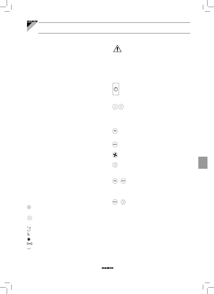
FWEC1 |
Standard electronic controller |
Manuel d'installation et d'utilisation
CARACTÉRISTIQUES GÉNÉRALES
Le contrôleur LCD a été conçu pour commander toutes les unités terminales de la gamme Daikin à moteur asynchrone
monophasé à plusieurs vitesses.
PRINCIPALES FONCTIONS
■Réglage de la température de l’air par variation automatique de la vitesse du ventilateur.
■Réglage de la température de l’air par commande On-Off du ventilateur à une vitesse fixe
■Contrôle de vannes On-Off pour systèmes à deux ou à quatre tubes.
■Gestion de la résistance d’appoint pour le chauffage.
■Commutation Rafraîchissement/Chauffage dans les modalités suivantes:
-manuelle sur l’appareil
-manuelle à distance (centralisée)
-automatique, en fonction de la température de l’eau
-automatique, en fonction de la température de l’air
Il est doté de:
■Entrée digitale 1 - Contacts libres pour commutation Rafraîchissement/Chauffage à distance centralisée (logique contact: voir les paramètres de configuration de la carte).
■Entrée digitale 2 - Contacts libres pour commande externe (par ex.: contact fenêtre, ON/OFF à distance, détecteur de présence, etc.) qui peut activer ou désactiver le fonctionnement de l’unité (logique contact: voir les paramètres de configuration de la carte).
■Sonde de température éloignée pour l’eau (FWTSK)
■Sonde de température éloignée pour l’air (FWTSK). Si présente, cette sonde est utilisée à la place de la sonde interne pour la lecture de la température ambiante.
Le panneau de commande se compose des éléments suivants:
■Moniteur LCD
■Clavier
MONITEUR LCD (VOIR FIGURE 1)
(1)Température ambiante
(2)État thermostat / ventilateur
(3)Température programmée
AUTO Logique de ventilation automatique  Vitesse ventilateur
Modalités de fonctionnement Rafraîchissement le voyant clignotant indique l’absence de signal eau de fonctionnement de la ventilation.
Modalités de fonctionnement Chauffage le voyant clignotant indique l’absence de signal eau de fonctionnement de la ventilation.
Option Economy activée Présence d’alarme
Contrôle Température minimum
Ouverture vanne
Résistance électrique. Le symbole clignotant indique que la résistance est en fonction. Le symbole allumé fixe indique uniquement la résistance sélectionnée.
____________________________________________________________
L'appareil n'est pas conçu pour être utilisé par des enfants ni par des personnes souffrant d'un quelconquehandicapphysique,sensorieloumental, ounepossédantpaslescompétencesnécessaires, en l'absence d'un responsable. Veiller à ce que les
enfants n'aient pas accès à l'appareil.
____________________________________________________________
CLAVIER (VOIR FIGURE 2)
Touche On/Off: allumage /extinction thermostat. Durant la procédure de modification des paramètres permet de revenir au fonctionnement normal
Touches Up et Down: modification de la température de réglage du Thermostat (Chauffage:[5.0- 30.0°C], rafraîchissement:[10.0-35.0°C]). Durant la procédure de modification des paramètres ces touches sont utilisées pour sélectionner les paramètres ou modifier leur valeur
Touche SEL: dans la modalité Chauffage, sélectionne la résistance électrique comme fonction auxiliaire
Touche Mode: sélection des modalités de fonctionnement Chauffage / Rafraîchissement
Touche Fan: sélection de la vitesse de fonctionnement
Touche EC: sélection de la modalité Economy
COMBINAISONS DE TOUCHES ACTIVES
Thermostat sur Off: allumé sur la procédure de configuration des paramètres
Thermostat sur On: affichage momentané de la température de l’eau
Sélection de la fonction de Température minimum Air
CONFIGURATION DE LA CARTE
La carte est configurable en fonction du type d’unité terminale/installation à contrôler, en modifiant des paramètres donnés.
LISTE DES PARAMÈTRES
■P00 = configuration commande (voir “Configurations Prévues”) pour sélectionner le type d’unité terminale à contrôler.
■P01 = type d’installation de la commande
-000: sur l’appareil
-001: murale
■P02 = (non utilisé)
FWEC1 |
Manuel d'installation et d'utilisation |
Standard electronic controller |
1 |
FC66002763 |
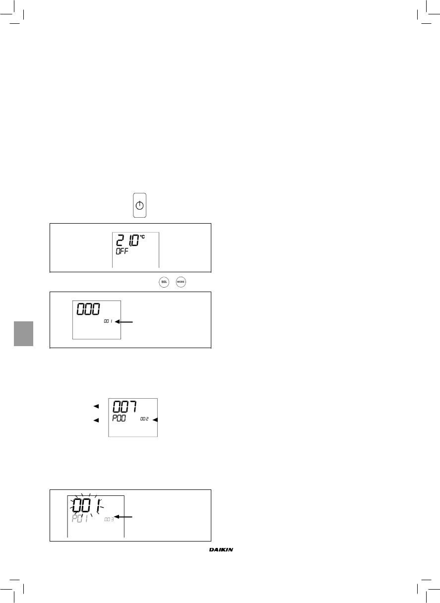
■P03 = zone neutre [20-50°C/10]; paramètre utilisé en cas de configuration avec sélection automatique Rafraîchissement/Chauffage en fonction de la température de l’air.
■P04 = sonde eau:
-000: non prévue
-001: prévue
Selon la valeur programmée, seront contrôlées l’alarme sonde et l’activation de la résistance électrique
■P05 = logique d’utilisation Entrée digitale 1 pour sélection Rafraîchissement/Chauffage:
-000: (ouvert/fermé) = (Rafraîch./Chauff.)
-001: (ouvert/fermé) = (Chauff./Rafraîch.)
■P06 = logique d’utilisation Entrée digitale 2 pour sélection On/Off:
-000: (ouvert/fermé) = (On/Off)
-001: (ouvert/fermé) = (Off/On)
PROCÉDURE DE CONFIGURATION DES
PARAMÈTRES
■ Porter le thermostat sur Off
■ Enfoncer simultanément les touches
Indication niveau: 1 = saisie MdP
■Utiliser les touches  pour modifier la valeur du moniteur jusqu’à la valeur du MdP 10, puis enforcer
  . S’il est correct, on aura accès aux paramètresper
|
|
Valeur paramètre |
|
|
||
|
|
sélectionné |
|
|
|
Indication niveau: |
|
|
|
|
|||
|
|
|
|
|
|
|
|
|
Paramètre |
|
|
|
001= saisie MdP |
|
|
|
|
|
|
|
|
|
sélectionné: P... |
|
|
||
|
|
|
|
|
|
|
■Utiliser les touches  pour faire défiler les différents paramètres (voir “List des paramètres, ci-dessus)
■Appuyer sur  pour activer la modification du paramètre (la valeur affichée commence à clignoter)
Indication niveau : 003 = saisie MdP
■Utiliser les touches  pour modifier la valeur
■Appuyer sur  pour sauvegarder la nouvelle valeur ou sur
  pour annuler la modification
■Une fois la modification des paramètres terminée, appuyer
sur la touche  pour quitter la procédure
NB La procédure de paramétrisation a une durée limitée.
À l’échéance de la période prévue (2 min. env.) le thermostat revient à l’état de OFF et ne conserve que les modifications sauvegardées.
CONFIGURATIONS PRÉVUES (PARAMÈTRE P00)
Le contrôleur LCD peut être configuré de façons différentes selon le type de système. Les différentes configurations s’obtiennent au moyen du paramètre P00 (voir procédure de configuration des paramètres de commande).
001
■Tuyaux installation: 2
■Vanne: non
■Résistance: non
■Vitesse ventilation: 3
■Logique sélection été / hiver: LOCALE MANUELLE
002
■Tuyaux installation: 2
■Vanne: NON
■Résistance: NON
■Vitesse ventilation: 3
■Logique sélection été / hiver: À DISTANCE MANUELLE
003
■Tuyaux installation: 2
■Vanne: NON
■Résistance: NON
■Vitesse ventilation: 3
■Logique sélection été / hiver: AUTOMATIQUE CÔTÉ EAU
004
■Tuyaux installation: 2
■Vanne: NON
■Résistance: NON
■Vitesse ventilation: 4
■Logique sélection été / hiver: LOCALE MANUELLE
005
■Tuyaux installation: 2
■Vanne: NON
■Résistance: NON
■Vitesse ventilation: 4
■Logique sélection été / hiver: À DISTANCE MANUELLE
006
■Tuyaux installation: 2
■Vanne: NON
■Résistance: NON
■Vitesse ventilation: 4
■Logique sélection été / hiver: AUTOMATIQUE CÔTÉ EAU
Manuel d'installation et d'utilisation |
FWEC1 |
2 |
Standard electronic controller |
FC66002763 |

CONFIGURATIONS PRÉVUES (PARAMÈTRE P00)
007
■Tuyaux installation: 2
■Vanne: NON
■Résistance: OUI
■Vitesse ventilation: 3
■Logique sélection été / hiver: LOCALE MANUELLE
008
■Tuyaux installation: 2
■Vanne: NON
■Résistance: OUI
■Vitesse ventilation: 3
■Logique sélection été / hiver: À DISTANCE MANUELLE
009
■Tuyaux installation: 2
■Vanne: NON
■Résistance: oui
■Vitesse ventilation: 3
■Logique sélection été / hiver: AUTOMATIQUE CÔTÉ AIR
010
■Tuyaux installation: 2
■Vanne: 2-3 VOIES
■Résistance: NON
■Vitesse ventilation: 3
■Logique sélection été / hiver: LOCALE MANUELLE
011
■Tuyaux installation: 2
■Vanne: 2-3 VOIES
■Résistance: NON
■Vitesse ventilation: 3
■Logique sélection été / hiver: À DISTANCE MANUELLE
012
■Tuyaux installation: 2
■Vanne: 2-3 VOIES
■Résistance: NON
■Vitesse ventilation: 3
■Logique sélection été / hiver: AUTOMATIQUE CÔTÉ EAU
013
■Tuyaux installation: 2
■Vanne: 2-3 VOIES
■Résistance: NON
■Vitesse ventilation: 4
■Logique sélection été / hiver: LOCALE MANUELLE
014
■Tuyaux installation: 2
■Vanne: 2-3 VOIES
■Résistance: NON
■Vitesse ventilation: 4
■Logique sélection été / hiver: À DISTANCE MANUELLE
015
■Tuyaux installation: 2
■Vanne: 2-3 VOIES
■Résistance: NON
■Vitesse ventilation: 4
■Logique sélection été / hiver: AUTOMATIQUE CÔTÉ EAU
016
■Tuyaux installation: 2
■Vanne: 3 VOIES
■Résistance: OUI
■Vitesse ventilation: 3
■Logique sélection été / hiver: LOCALE MANUELLE
017
■Tuyaux installation: 2
■Vanne: 3 VOIES
■Résistance: OUI
■Vitesse ventilation: 3
■Logique sélection été / hiver: À DISTANCE MANUELLE
018
■Tuyaux installation: 2
■Vanne: 3 VOIES
■Résistance: OUI
■Vitesse ventilation: 3
■Logique sélection été / hiver: AUTOMATIQUE CÔTÉ AIR
019
■Tuyaux installation: 4
■Vanne: NON
■Résistance: NON
■Vitesse ventilation: 3
■Logique sélection été / hiver: LOCALE MANUELLE
020
■Tuyaux installation: 4
■Vanne: NON
■Résistance: NON
■Vitesse ventilation: 3
■Logique sélection été / hiver: À DISTANCE MANUELLE
021
■Tuyaux installation: 4
■Vanne: NON
■Résistance: NON
■Vitesse ventilation: 3
■Logique sélection été / hiver: AUTOMATIQUE CÔTÉ AIR
022
■Tuyaux installation: 4
■Vanne: NON
■Résistance: NON
■Vitesse ventilation: 4
■Logique sélection été / hiver: LOCALE MANUELLE
023
■Tuyaux installation: 4
■Vanne: NON
■Résistance: NON
■Vitesse ventilation: 4
■Logique sélection été / hiver: À DISTANCE MANUELLE
024
■Tuyaux installation: 4
■Vanne: NON
■Résistance: NON
■Vitesse ventilation: 4
■Logique sélection été / hiver: AUTOMATIQUE CÔTÉ AIR
|
|
|
|
|
|
|
|
|
|
|
|
|
|
|
|
|
|
FWEC1 |
Manuel d'installation et d'utilisation |
|
|
|
|
|
|
|
Standard electronic controller |
3 |
|
|
|
|
|
|
|
FC66002763 |
|
|
|
|
|
|
|
|
|
|
|
|
|
|
|
|
|
|
|
|
|
|
|
|
|
|
|
|
|
|
|
|
|
|
|
|
|
|
|
|
|
|
|
|
|
|
|
|
|
|
|
|
|
|
|
|
|
|
|
|
|
|
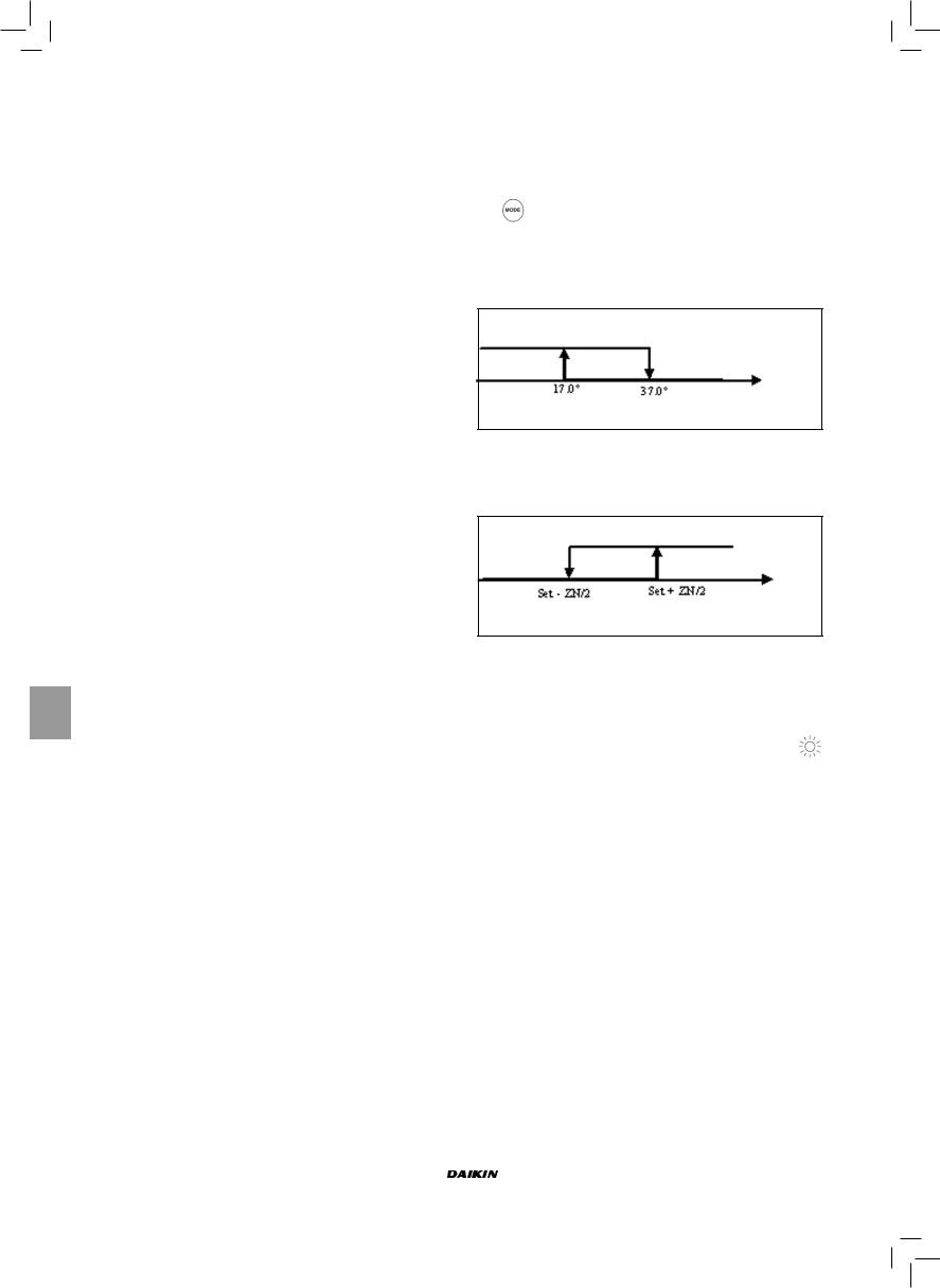
025
■Tuyaux installation: 4
■Vanne: 2-3 VOIES
■Résistance: NON
■Vitesse ventilation: 3
■Logique sélection été / hiver: LOCALE MANUELLE
026
■Tuyaux installation: 4
■Vanne: 2-3 VOIES
■Résistance: NON
■Vitesse ventilation: 3
■Logique sélection été / hiver: À DISTANCE MANUELLE
027
■Tuyaux installation: 4
■Vanne: 2-3 VOIES
■Résistance: NON
■Vitesse ventilation: 3
■Logique sélection été / hiver: AUTOMATIQUE CÔTÉ AIR
028
■Tuyaux installation: 4
■Vanne: 2-3 VOIES
■Résistance: NON
■Vitesse ventilation: 3 + CN (CONVECTION NATURELLE)
■Logique sélection été / hiver: LOCALE MANUELLE
029
■Tuyaux installation: 4
■Vanne: 2-3 voies
■Résistance: NON
■Vitesse ventilation: 3 + CN (CONVECTION NATURELLE)
■Logique sélection été / hiver: À DISTANCE MANUELLE
030
■Tuyaux installation: 4
■Vanne: 2-3 VOIES
■Résistance: NON
■Vitesse ventilation: 3 + CN (CONVECTION NATURELLE)
■Logique sélection été / hiver: AUTOMATIQUE CÔTÉ AIR
031
■Tuyaux installation: 4
■Vanne: NON
■Résistance: OUI
■Vitesse ventilation: 3
■Logique sélection été / hiver: LOCALE MANUELLE
LOGIQUES
SÉLECTION RAFRAÎCHISSEMENT/CHAUFFAGE
Sont présentes 4 logiques différentes de sélection du mode de fonctionnement du thermostat, lesquelles sont définies sur la base de la configuration programmée sur la commande:
■Locale manuelle: choix de l’utilisateur en utilisant la touche
■À distance manuelle: en fonction de l’état de l’Entrée Digitale 1 (logique contact: voir les paramètres de configuration de la carte).
■Automatique en fonction de la température de l’eau
Été
Hiver
Temp. eau
NB: dans le cas d’une alarme relative aux sondes le contrôle de la modalité revient momentanément à la modalité locale
■ Automatique en fonction de la température de l’air:
Été
Hiver
Temp. air
Où:
-Set est la température programmée au moyen des flèches
-ZN est la zone neutre (paramètre P03)
Le mode de fonctionnement du thermostat est identifiée sur
le moniteur par les symboles  (Rafraîchissement) et (Chauffage)
|
|
|
|
|
|
|
|
|
|
|
|
|
|
|
|
|
|
|
|
|
|
|
|
|
|
|
|
|
|
|
|
|
|
|
|
|
|
|
|
|
|
|
|
|
|
|
|
|
|
|
|
|
|
|
|
|
|
|
|
|
|
|
|
|
|
|
|
|
|
|
|
|
|
|
|
|
|
|
|
|
|
|
|
|
|
|
|
|
|
|
|
|
|
|
|
|
Manuel d'installation et d'utilisation |
FWEC1 |
|
|
|
|
|
|
|
4 |
Standard electronic controller |
|
|
|
|
|
|
|
FC66002763 |
|
|
|
|
|
|
|
|
|
|
|
|
|
|
|
|
|
|
|
|
|
|
|
|
|
|
|
|
|
|
|
|
|
|
|
|
|
|
|
|
|
|
|
|
|
|
|
|
|
|
|
|
|
|
|
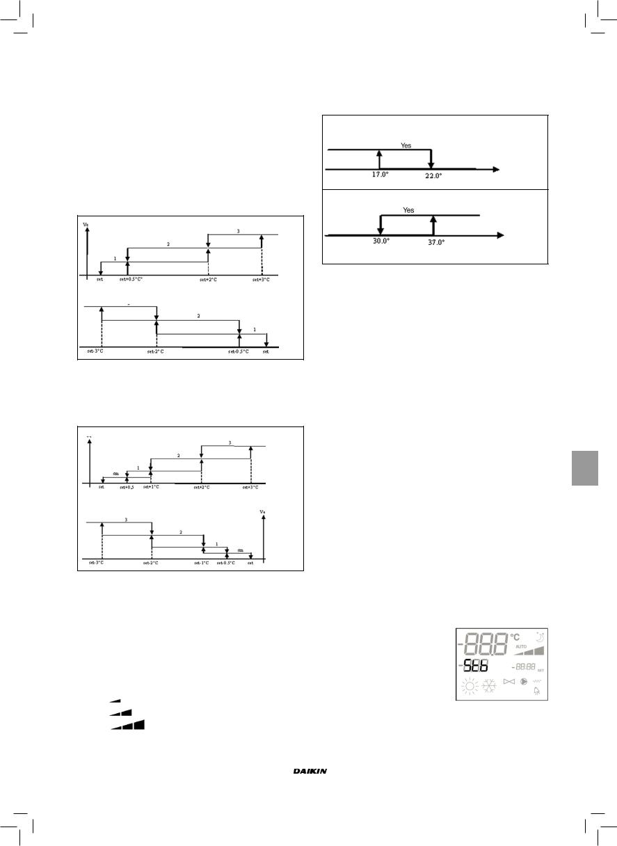
VENTILATION
Le contrôleur est capable de gérer les unités à 3 ou 4 vitesses de ventilation
SÉLECTION DE LA VITESSE DE FONCTIONNEMENT
À l’aide de la touche Fan  on peut choisir les vitesses suivantes:
■AUTO Vit. automatique: en fonction de la température programmée et de celle de l’air ambiant
Pour configurations à 3 vitesses: où
1 = vitesse minimum
2 = vitesse moyenne
3 = vitesse maximum
RAFRAÎCHISSEMENT
Temp. air
CHAUFFAGE
Temp. air
Pour configurations à 4 vitesses: où
sm = vitesse extra-minimum 1 = vitesse minimum
2 = vitesse moyenne
3 = vitesse maximum
RAFRAÎCHISSEMENT
Temp. air
CHAUFFAGE
Temp. air
NB: pour les configurations à 4 vitesses et vanne ou 3 vitesses + CN, la ventilation dans le mode chauffage est remontée de 0,5°C pour permettre la convection naturelle dans la première phase.
■AUCUN SYMBOLE: Vit. désactivée. Sélectionnable uniquement dans le mode chauffage et avec configurations
à4 ou à 3 vitesses + CN, l’unité terminale fonctionne par convection naturelle seulement
■ Vit. extra-minimum. Sélectionnable uniquement avec configurations à 4 vitesses, la vitesse utilisée étant extra-minimum
Vit. minimum
Vit. moyenne
Vit. maximum
NB Dans le cas de vitesse fixe, la logique d’activation du ventilateur correspondra à celle de la logique automatique.
ACTIVATION EAU
Le fonctionnement de la ventilation est lié au contrôle de la température de l’eau de l’installation. Compte tenu du mode de fonctionnement on aura différents seuils d’activation en mode chauffage et rafraîchissement.
RAFRAÎCHISSEMENT
Temp. eau
CHAUFFAGE
Temp. eau
L’absence de cette commande à l’appel du thermostat sera indiquée sur le moniteur par le clignotement du symbole du
mode actif ( ou
ou  )
)
Cette commande est ignorée dans les cas suivants:
■Sonde eau non prévue (P04 = 0) ou sous alarme étant débranchée.
■Mode Rafraîchissement avec configurations à 4 tubes.
FORÇAGES
La logique de ventilation normale est ignorée dans le cas de situations particulières de forçage pouvant être nécessaires pour le contrôle correct de la température ou le fonctionnement de l’unité. Fonctions disponibles:
mode Rafraîchissement:
■commande installée sur l’unité (P01 = 0) et configuration avec vanne: la vitesse minimum disponible est maintenue après avoir atteint la température fixée.
■Commande installée sur l’unité et configuration sans vanne: toutes les 10 minutes d’arrêt du ventilateur est effectué un nettoyage de 2 minutes à la vitesse moyenne pour permettre une lecture plus précise de la température ambiante par la sonde air.
mode Chauffage
■Résistance active: la ventilation est forcée à la moyenne vitesse.
■Résistance éteinte: pendant 2 minutes est maintenue une post-ventilation à la moyenne vitesse. (NB: la ventilation est complétée même si le thermostat est éteint ou en cas de commutation sur la modalité rafraîchissement)
MONITEUR
Le moniteur affiche l’état du ventilateur
■Stb: ventilateur en standby
■On: ventilateur allumé
■noF: ventilateur désactivé pour fonctionner dans la modalité convection naturelle seulement
FWEC1 |
Manuel d'installation et d'utilisation |
Standard electronic controller |
5 |
FC66002763 |
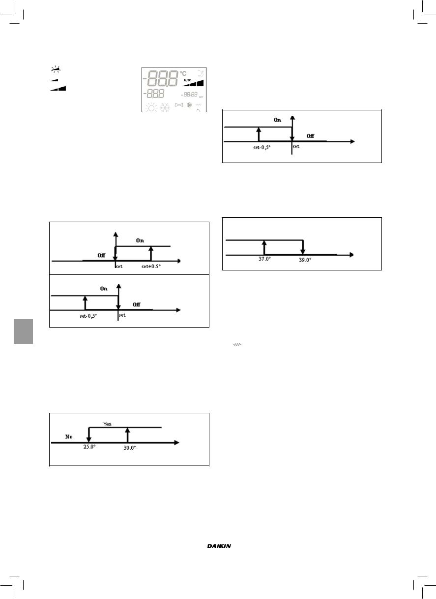
Le moniteur affiche la vitesse de fonctionnement (avec indication éventuelle de la logique “automatique”) active ou sélectionnée (dans le cas de ventilateur en stand-by)
Vit. extra-minimum
Vit. minimum
Vit. moyenne
 Vit. maximum
NB: si la vitesse activée ne correspond pas à la vitesse sélectionnée par l’utilisateur (cas de forçage), à la
première pression de la touche  est affichée cette dernière; la pression suivante modifie la sélection.
VANNE
Le contrôleur est capable de gérer les vannes à 2 ou 3 voies de type ON/OFF, le capteur étant alimenté à 230 V.
OUVERTURE
L’ouverture de la vanne est commandée en fonction du set point de service et de la température de l’air
RAFRAÎCHISSEMENT
Temp. air
CHAUFFAGE
Temp. air
ACTIVATION EAU
Le contrôle de la température de l’eau pour activer l’ouverture est prévu uniquement dans les configurations avec vannes à 3 voies et résistance électrique. Avec ces configurations le contrôle de la température est effectué dans les cas suivants:
■Chauffage avec résistance: le fonctionnement de la résistance comporte un forçage de la ventilation. Il est donc nécessaire d’éviter le passe d’eau trop froide dans l’unité.
Temp. eau
■Post ventilation due à l’extinction de la résistance: maintenue jusqu’à l’échéance du temps établi même si la modalité de fonctionnement est modifiée. Durant la post-ventilation la fonction eau coïncide avec la fonction ventilation.
MONITEUR
L’indication de vanne activée sur le moniteur est donnée par le symbole 
RÉSISTANCE ÉLECTRIQUE
La résistance électrique est un dispositif ayant la fonction d’appoint dans la phase de chauffage.
SÉLECTION
Si prévue par la configuration, la résistance peut être sélectionnée en mode chauffage à l’aide de la touche Sel  .
.
ACTIVATION
Temp. air
La résistance électrique sélectionnée par l’utilisateur est activée par le thermostat en fonction de la température ambiante
NB: l’activation comporte une ventilation forcée
ACTIVATION EAU
CHAUFFAGE
ON
OFF
Temp. eau
La commande d’activation de la résistance est liée au contrôle de la température de l’eau. Ci-dessous, la logique d’activation.
Cette commande ne sera pas fournie si la sonde n’est pas prévue ou est désactivée
MONITEUR
Le moniteur affiche les informations suivantes
■résistance sélectionnée par l’utilisateur: symbole fixe
■résistance active: symbole  clignotant
Manuel d'installation et d'utilisation |
FWEC1 |
6 |
Standard electronic controller |
FC66002763 |
 Loading...