


Daikin FTXN25MV1B9, RXN25MV1B9, FTXN35MV1B9, RXN35MV1B9, FTXN50MV1B9 Installation manuals
...INSTALLATION MANUAL
R410A SPLIT SERIES
INVERTER
MODELS
FTXN25MV1B9 RXN25MV1B9 FTXN35MV1B9 RXN35MV1B9 FTXN50MV1B9 RXN50MV1B9 FTXN60MV1B9 RXN60MV1B9
Installation Manual |
English |
|
R410A Split Series |
||
|
||
Manuel d’installation |
|
|
|
||
Français |
||
Série split R410A |
||
|
||
Installationsanleitung |
|
|
|
||
Deutsch |
||
Split-Baureihe R410A |
||
|
||
Manuale d’installazione |
|
|
|
||
Italiano |
||
Serie Multiambienti R410A |
||
|
||
Manual de instalación |
|
|
|
||
Español |
||
Serie Split R410A |
||
|
||
Руководство по монтажу |
|
|
|
||
Русский |
||
Серия R410A с раздельной установкой |
||
|
||
Montaj kılavuzu |
|
|
|
||
Türkçe |
||
R410A Split serisi |
||
|
||
|
|
IM-5WMYJ-0214(0)-DAIKIN
Part Number.: R08019039282

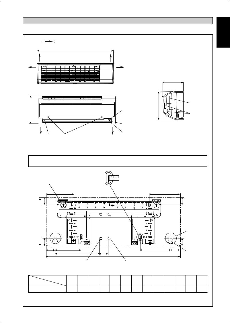
OUTLINE AND DIMENSIONS
Indoor Unit [FTXN]
THE MARK |
SHOWS PIPING DIRECTION |
|
|
|
A |
|
|
REAR |
REAR |
|
|
LEFT |
RIGHT |
|
|
|
|
C |
|
|
TOP VIEW |
|
|
|
<![if ! IE]> <![endif]>B |
|
NAME PLATE |
|
|
|
|
| <![if ! IE]> <![endif]>B |
SIGNAL RECEIVER |
|
TERMINAL |
|
|
|
BLOCK |
|
|
|
WITH EARTH |
|
INDOOR UNIT |
SIDE VIEW |
TERMINAL |
|
ON/OFF SWITCH |
|
|
BOTTOM |
|
|
|
BOTTOM |
|
|
|
|
ROOM TEMPERATURE |
|
|
LOUVER |
THERMISTOR (INSIDE) |
|
|
FRONT GRILLE FIXED SCREWS (INSIDE)
FRONT VIEW
NOTE: PLEASE BASED ON ACTUAL INSTALLATION PLATE DESIGN IN THE UNIT FOR INSTALLATION PLATE 25/35 DIMENSION REFERENCE AT PAGE 1&2.
«Recommended mounting plate retention spots (5 spots in all)
D
<![if ! IE]><![endif]>F
<![if ! IE]><![endif]>B
Use tape measure as shown.
Position the end of a tape measure at Ñ
E
F
Through the wall hole Ø 65mm
| <![if ! IE]> <![endif]>G |
|
|
|
|
|
|
|
|
|
|
|
G |
|
|
|
|
|
|
|
|
|
|
|
|
|
|
|
||
H |
J |
|
L |
M |
|
|
|
|
K |
|
I |
|
|
|
|
|
|
A |
|
|
|
|
|
Drain hose position |
|||||
|
|
|
|
|
|
|
|
|
|
|||||
|
|
Liquid pipe end |
|
Gas pipe end |
|
|
|
|
|
|
||||
|
|
|
|
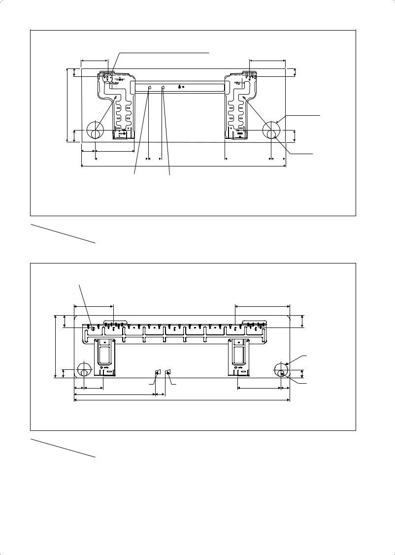
INSTALLATION PLATE 25/35 |
|
|
|
|
|
|
||||
Dimension |
A |
B |
C |
D |
E |
F |
G H |
I |
J |
K |
L M |
|||
Model |
||||||||||||||
|
|
|
|
|
|
|
|
|
|
|
|
|
||
25/35 |
800 |
288 |
204 |
166 |
184 |
42 |
46 |
55 |
56 |
154 |
182 |
263 |
52 |
|
All dimensions are in mm
<![endif]>Original Instruction English
1-1
<![endif]>F
<![if ! IE]><![endif]>B
<![if ! IE]><![endif]>G
«Recommended mounting plate retention spots (5 spots in all)
D E
H J
L |
|
|
M |
A |
K |
|
I |
Liquid pipe end |
|
|
|
|
|||
|
Gas pipe end |
|
|||||
<![endif]>F
Through the wall hole Ø 65mm
<![if ! IE]><![endif]>G
Drain hose position
ALTERNATIVE INSTALLATION PLATE 25/35
All dimensions are in mm
Model |
Dimension |
A |
B |
C |
D |
E |
F |
G |
H |
I |
J |
K |
L |
M |
|
||||||||||||||
|
|
|
|
|
|
|
|
|
|
|
|
|
|
|
|
|
|
|
|
|
|
|
|
|
|
|
|
|
|
25/35 |
|
800 |
288 |
204 |
104 |
141 |
30 |
46 |
55 |
56 |
153 |
181 |
207 |
52 |
|
|
|
|
|
|
|
|
|
|
|
|
|
|
|
«Recommended mounting plate retention spots (7 spots in all)
D |
E |
| <![if ! IE]> <![endif]>F |
<![if ! IE]> <![endif]>F |
<![endif]>B
|
|
|
|
|
|
Through the wall |
|
|
|
|
|
|
hole Ø 65mm |
| <![if ! IE]> <![endif]>G |
|
|
|
|
|
<![if ! IE]> <![endif]>G |
H |
J |
Liquid pipe end |
Gas pipe end |
K |
I |
Drain hose position |
|
|
L |
M |
|
|
|
|
|
|
A |
|
|
|
|
|
|
INSTALLATION PLATE 50/60 |
|
|
|
All dimensions are in mm
Model |
Dimension |
A |
B |
C |
D |
E |
F |
G |
H |
I |
J |
K |
L |
M |
|
||||||||||||||
|
|
|
|
|
|
|
|
|
|
|
|
|
|
|
|
|
|
|
|
|
|
|
|
|
|
|
|
|
|
50/60 |
|
1065 |
310 |
228 |
190 |
173 |
61 |
40 |
45 |
48 |
91 |
219 |
580 |
45 |
|
|
|
|
|
|
|
|
|
|
|
|
|
|
|
1-2

Outdoor Unit [RXN]
All dimensions are in mm
|
J |
H |
I |
|
<![if ! IE]> <![endif]>G |
|
<![if ! IE]> <![endif]>O |
|
|
|
<![if ! IE]> <![endif]>N |
|
|
|
<![if ! IE]> <![endif]>Q |
|
|
|
<![if ! IE]> <![endif]>P |
E |
F 2.0 D |
B |
C |
<![endif]>M K L
<![if ! IE]><![endif]>A
Model |
Dimension |
A |
B |
C |
D |
E |
F |
G |
H |
I |
J |
K |
L |
M |
N |
O |
P |
Q |
|
||||||||||||||||||
|
|
|
|
|
|
|
|
|
|
|
|
|
|
|
|
|
|
|
|
|
|
|
|
|
|
|
|
|
|
|
|
|
|
|
|
|
|
25/35 |
|
550 |
658 |
51 |
11 |
273 |
16 |
14 |
470 |
96 |
93 |
94 |
60 |
14 |
133 |
8 |
10 |
299 |
|
|
|
|
|
|
|
|
|
|
|
|
|
|
|
|
|
|
|
L K
A
3.0 |
O |
D |
|
|
|
|
V |
|
| <![if ! IE]> <![endif]>B |
|
|
| <![if ! IE]> <![endif]>P |
|
|
L |
|
|
All dimensions are in mm |
|
<![if ! IE]> <![endif]>N |
|
|
|
|
|
|
| <![if ! IE]> <![endif]>M |
| <![if ! IE]> <![endif]>Q |
| <![if ! IE]> <![endif]>N |
|
C |
|
|
<![if ! IE]> <![endif]>F |
G |
H |
U |
|
|
|
|
<![if ! IE]> <![endif]>E |
|
|
| <![if ! IE]> <![endif]>S |
|
|
|
| <![if ! IE]> <![endif]>R |
|
|
|
|
|
I |
J |
|
|
T |
|
Model |
Dimension |
A |
B |
C |
D |
E |
F |
G |
H |
I |
J |
K |
L |
M |
N |
|
|||||||||||||||
|
|
|
|
|
|
|
|
|
|
|
|
|
|
|
|
|
|
|
|
|
|
|
|
|
|
|
|
|
|
|
|
50/60 |
|
855 |
730 |
328 |
520 |
179 |
46 |
93 |
149 |
101 |
113 |
603 |
126 |
164 |
15 |
|
|
|
|
|
|
|
|
|
|
|
|
|
|
|
|
|
|
|
|
|
|
|
|
|
|
|
|
|
|
|
|
Model |
Dimension |
O |
P |
Q |
R |
S |
T |
U |
V |
|
|
|
|
|
|
|
|
|
|
|
|
|
|||||||||
|
|
|
|
|
|
|
|
|
|
|
|
|
|
|
|
|
|
|
|
|
|
|
|
|
|
|
|
|
|
|
|
50/60 |
|
34 |
23 |
362 |
73 |
75 |
8 |
67 |
7 |
|
|
|
|
|
|
|
|
|
|
|
|
|
|
|
|
|
|
|
|
|
|
<![endif]>English
1-3
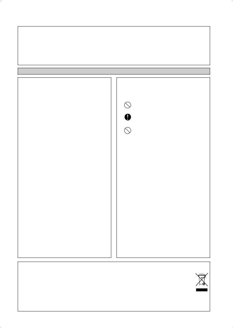
INSTALLATION MANUAL
This manual provides the procedures of installation to ensure a safe and good standard of operation for the air conditioner unit. Special adjustment may be necessary to suit local requirement.
Before using your air conditioner, please read this instruction manual carefully and keep it for future reference.
This appliance is intended to be used by expert or trained users in shops, in light industry and on farms, or for commercial use by lay persons.
This appliance is not intended for use by persons, including children, with reduced physical, sensory or mental capabilities, or lack of experience and knowledge, unless they have been given supervision or instruction concerning use of the appliance by a person responsible for their safety.
Children should be supervised to ensure that they do not play with the appliance.
SAFETY PRECAUTIONS
!WARNING
•Installation and maintenance should be performed by qualified persons who are familiar with local code and regulation, and experienced with this type of appliance.
•All field wiring must be installed in accordance with the national wiring regulation.
•Ensure that the rated voltage of the unit corresponds to that of the name plate before commencing wiring work according to the wiring diagram.
•The unit must be GROUNDED to prevent possible hazard due to insulation failure.
•All electrical wiring must not touch the water piping or any moving parts of the fan motors.
•Confirm that the unit has been switched OFF before installing or servicing the unit.
•Disconnect from the main power supply before servicing the air conditioner unit.
•DO NOT pull out the power cord when the power is ON. This may cause serious electrical shocks which may result in the fire hazards.
•Keep the indoor and outdoor units, power cable and transmission wiring, at least 1m from TVs and radios, to prevent distorted pictures and static. {Depending on the type and source of the electrical waves, static may be heard even when more than 1m away}.
! CAUTION
Please take note of the following important points when installing.
•Do not install the unit where leakage of flammable gas may occur.
If gas leaks and accumulates around the unit, it may cause fire ignition.
•Ensure that drainage piping is connected properly.
If the drainage piping is not connected properly, it may cause water leakage which will dampen the furniture.
• Do not overcharge the unit.
This unit is factory pre-charged.
Overcharge will cause over-current or damage to the compressor.
•Ensure that the unit’s panel is closed after service or installation.
 Unsecured panels will cause the unit to operate noisily.
•Sharp edges and coil surfaces are potential locations which may cause injury hazards.Avoid from being in contact with these places.
•Before turning off the power supply, set the remote
controller’s ON/OFFswitch to the “OFF” position to prevent the nuisance tripping of the unit. If this is not done, the unit’s fans will start turning automatically when power resumes, posing a hazard to service personnel or the user.
•Do not install the units at or near doorway.
•Do not operate any heating apparatus too close to the air conditioner unit or use in room where mineral oil, oil vapour or oil steam exist, this may cause plastic part to melt or deform as a result of excessive heat or chemical reaction.
•When the unit is used in kitchen, keep flour away from going into suction of the unit.
•This unit is not suitable for factory used where cutting oil mist or iron powder exist or voltage fluctuates greatly.
•Do not install the units at area like hot spring or oil refinery plant where sulphide gas exists.
•Ensure the color of wires of the outdoor unit and the terminal markings are same to the indoors respectively.
•IMPORTANT: DO NOT INSTALL OR USE THE AIR CONDITIONER UNIT IN A LAUNDRY ROOM.
•Don’t use joined and twisted wires for incoming power supply.
•The equipment is not intended for use in a potentially explosive atmosphere.
NOTICE
Disposal requirements
Your air conditioning product is marked with this symbol. This means that electrical and electronic products shall not be mixed with unsorted household waste.
Do not try to dismantle the system yourself: the dismantling of the air conditioning system, treatment of the refrigerant, of oil and of other parts must be done by a qualified installer in accordance with relevant local and national legislation.
Air conditioners must be treated at a specialized treatment facility for re-use, recycling and recovery. By ensuring this product is disposed of correctly, you will help to prevent potential negative consequences for the environment and human health. Please contact the installer or local authority for more information.
Batteries must be removed from the remote controller and disposed of separately in accordance with relevant local and national legislation.
1-4
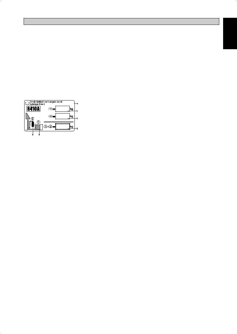
IMPORTANT
Important information regarding the refrigerant used
This product contains fluorinated greenhouse gases covered by the Kyoto Protocol.
Do not vent gases into the atmosphere.
Refrigerant type: |
R410A |
GWP (1) value: |
1975 |
(1) GWP = Global Warming Potential Please fill in with indelible ink,
¢1 the factory refrigerant charge of the product,
¢2 the additional refrigerant amount charged in the field and
¢1 + 2 the total refrigerant charge
on the refrigerant charge label supplied with the product.
The filled out label must be adhered in the proximity of the product charging port (e.g. onto the inside of the service cover).
1 factory refrigerant charge of the product: see unit name plate (2)
2 additional refrigerant amount charged in the field
3 total refrigerant charge
4 contains fluorinated greenhouse gases covered by the Kyoto Protocol
5 outdoor unit
6refrigerant cylinder and manifold for charging
(2)In case of multiple indoor systems, only 1 label must be adhered*, mentioning the total factory refrigerant charge of all indoor units connected in the refrigerant system.
Periodical inspections for refrigerant leaks may be required depending on European or local legislation. Please contact your local dealer for more information.
* on the outdoor unit
<![endif]>English
1-5
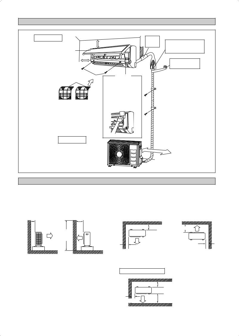
INSTALLATION DIAGRAM
Indoor Unit
30mm or more from ceiling
Front panel
50mm or more from walls (on both sides)
Air filter |
M4 x 12L |
Service lid |
|
ó Opening service lid |
|||
|
|||
|
Service lid is opening/ |
||
|
closing type. |
||
|
ó Opening method |
||
|
1) |
Remove the service lid |
|
|
|
screws. |
|
|
2) |
Pull out the service lid |
|
|
|
diagonally down in the |
|
|
|
direction of the arrow. |
|
|
3) |
Pull down. |
|
Caulk pipe hole gap with putty.
Cut thermal insulation pipe to an appropriate length and wrap it with tape, making sure that no gap is left in the insulation pipe’s cut line.
Wrap the insulation pipe with the finishing tape from bottom to top.
Outdoor Unit
500mm |
from wall |
INSTALLATION OF THE OUTDOOR UNIT (RXN25/35)
•Where a wall or other obstacle is in the path of outdoor unit’s intake or exhaust airflow, follow the installation guidelines below.
•For any of the below installation patterns, the wall height on the exhaust side should be 1200mm or less.
|
Wall facing one side |
|
|
Wall facing two sides |
More than 50 |
More than 100 |
|||
1200 or |
More |
|
than 100 |
||
less |
||
|
||
|
More than 50 |
More than 150 |
More than 50
Side View |
|
Top View |
|
Wall facing three sides |
|
|
|
More than 150 |
|
More than 50 |
More than 300 |
|
|
|
|
|
Top View |
Unit : mm
1-6
Drain work. (Heat Pump Unit Only)
1)Use drain plug for drainage.
2)If the drain port is covered by a mounting base or floor surface, place additional foot bases of at least 30mm in height under the outdoor unit’s feet.
3)In cold areas, do not use a drain hose with the outdoor unit. (Otherwise, drain water may freeze, impairing heating performance.)
Drain water hole
Bottom frame
Drain Plug
Hose (available comercially, inner dia. 16mm)
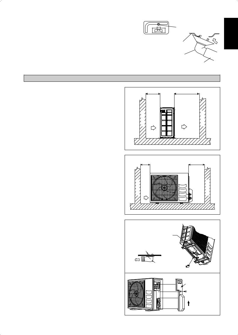
INSTALLATION OF THE OUTDOOR UNIT (RXN50/60)
The outdoor unit must be installed in such a way, so as to prevent short circuit of the hot discharged air or obstruction to the smooth air flow. Please follow the installation clearances shown in the figure. Select the coolest possible place where intake air temperature is not greater than the outside air temperature (Refer to operating range).
Installation clearances
Dimension |
A |
B |
C |
D |
|
|
|
|
|
Minimum Distance, mm |
300 |
1000 |
300 |
500 |
|
|
|
|
|
Note: If there is any obstacle higher than 2m, or if there is any obstruction at the upper part of the unit, please allow more space than the figure indicated in the above table.
Condensed Water Disposal Of Outdoor Unit
(Heat Pump Unit Only)
•There are 2 holes on the base of Outdoor Unit for condensed water to flow out. Insert the drain elbow to one of the holes.
•To install the drain elbow, first insert one portion of the hook to the base (portion A), then pull the drain elbow in the direction shown by the arrow while inserting the other portion to the base. After installation, check to ensure that the drain elbow clings to base firmly.
•If the unit is installed in a snowy and chilly area, condensed water may freeze in the base. In such case, please remove plug at the bottom of unit to smooth the drainage.
|
A |
B |
|
| <![if ! IE]> <![endif]>Obstacle |
<![if ! IE]> <![endif]>Return air |
<![if ! IE]> <![endif]>Discharge air |
<![if ! IE]> <![endif]>Obstacle |
|
C |
|
D |
| <![if ! IE]> <![endif]>Obstacle |
<![if ! IE]> <![endif]>Return air |
<![if ! IE]> <![endif]>Service access |
<![if ! IE]> <![endif]>Obstacle |
PLUG |
A |
BASE |
DRAIN ELBOW |
DRAIN ELBOW |
Please remove side |
plate when connecting |
the piping and |
connecting cord |
PUSH & PULL UP |
<![endif]>English
1-7

INSTALLATION OF THE INDOOR UNIT
The indoor unit must be installed in such a way so as to prevent short circuit of the cool discharged air with the hot return air. Please follow the installation clearance shown in the figure. Do not place the indoor unit where there could be direct sunlight shining on it. Also, this location must be suitable for piping and drainage, and be away from doors or windows.
Air flow |
|
<![if ! IE]> <![endif]>min. 30 (Space for performance) |
|
(Indoor) |
|
||
|
|
||
min. 50 |
Required space |
min. 50 |
|
(Space for |
(Space for |
||
|
|||
maintenance) |
|
maintenance) |
|
|
All dimensions are in mm |
||
The refrigerant piping can be routed to the unit in a number of ways (left or right from the back of the unit), by using the cut-out holes on the casing of the unit. Bend the pipes carefully to the required position in order to align it with the holes. For the side and bottom out, hold the bottom of the piping and then position it to the required direction. The condensation drain hose can be taped to the pipes.
Right-side, right-back or right-bottom piping
Right-side piping |
|
|
Remove pipe port cover |
Right-back piping |
|
|
||
here for right-side piping Right-bottom |
|
|
piping |
Bind coolant pipe |
|
Remove pipe port cover |
and drain hose |
|
together with |
||
here for right-bottom piping |
||
insulating tape. |
||
|
||
Left-side, left-back or left-bottom piping |
||
|
Remove pipe port |
|
|
cover here for |
|
|
left-side piping |
|
|
Left-side piping |
Remove pipe port cover |
Left-back piping |
here for left-bottom piping |
|
Left-bottom piping |
|
1-8
Mounting Installation Plate
Ensure that the wall is strong enough to withstand the weight of the unit. Otherwise, it is necessary to reinforce the wall with plates, beams or pillars.
Use the level gauge for horizontal mounting, and fix it with 5 suitable screws for FTXN25/35 and 7 suitable screws for FTXN50/60.
In case the rear piping draws out, drill a hole 65mm in diameter with a cone drill, slightly lower on the outside wall (see figure).
FTXN 25/35 |
Mounting plate |
Mounting plate fixing screw
FTXN 25/35 (ALTERNATIVE INSTALLATION PLATE)
Mounting plate
Mounting plate fixing screw
FTXN 50/60 |
Mounting plate |
|
Mounting plate fixing screw 
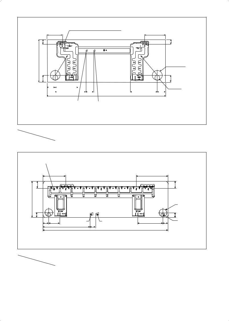
Recommended Mounting Plate Retention Spots And
Dimensions
FTXN 25/35
« Recommended mounting plate retention spots |
|
Use tape measure as shown. |
|
|
|||
|
Position the end |
of a tape measure at Ñ |
|||||
(5 spots in all) |
|
|
|
||||
166 |
|
|
|
184 |
|
|
|
|
|
|
|
|
|
||
| <![if ! IE]> <![endif]>42.2 |
|
|
|
|
|
|
<![if ! IE]> <![endif]>42.2 |
| <![if ! IE]> <![endif]>288 |
|
|
|
|
|
|
|
|
|
|
|
|
|
|
Through the wall hole Ø 65mm |
| <![if ! IE]> <![endif]>45.9 |
153.8 |
|
|
|
181.7 |
55.5 |
<![if ! IE]> <![endif]>45.9 |
54.5 |
263 |
51.9 |
|
Drain hose position |
|||
|
|
800 |
|
|
|||
|
|
|
|
|
|
|
|
|
Liquid pipe end |
|
Gas pipe end |
All dimensions are in mm |
|||
FTXN 25/35 (ALTERNATIVE INSTALLATION PLATE)
«Recommended mounting plate retention spots (5 spots in all)
104 |
|
|
|
141 |
| <![if ! IE]> <![endif]>30 |
|
|
|
<![if ! IE]> <![endif]>30 |
| <![if ! IE]> <![endif]>288 |
|
|
|
Through the wall hole Ø 65mm |
|
|
|
|
|
| <![if ! IE]> <![endif]>46 |
|
|
|
<![if ! IE]> <![endif]>46 |
|
153 |
|
|
Drain hose position |
55 |
207 |
52 |
181 |
56 |
|
|
|
800 |
|
Liquid pipe end |
|
Gas pipe end |
All dimensions are in mm |
|
|
|
|
|
|
FTXN 50/60
«Recommended mounting plate retention spots (7 spots in all)
190 |
173 |
| <![if ! IE]> <![endif]>61 |
<![if ! IE]> <![endif]>61 |
| <![if ! IE]> <![endif]>310 |
|
|
|
|
|
Through the wall hole |
|
|
|
|
|
|
Ø 65mm |
| <![if ! IE]> <![endif]>40 |
|
|
|
|
|
<![if ! IE]> <![endif]>40 |
45 91 |
Liquid pipe end |
|
Gas pipe end |
219 |
48 |
Drain hose position |
|
580 |
45 |
1065 |
|
|
|
All dimensions are in mm
Hole with cone drill
Inside |
Outside |
Wall embedded pipe |
Caulking |
(Field supply) |
Ø 65
Wall hole cover (Field supply)
Wall embedded pipe (Field supply)
Mount The Unit Onto The Installation Plate
Hook the indoor unit onto the upper portion of the installation plate (Engage the two hooks at the rear top of the indoor unit with the upper edge of the installation plate). Ensure that the hooks are properly seated on the installation plate by moving it to the left and right.
How To Attach The Indoor Unit
Hook the claws of the bottom frame to the mounting plate.
How To Remove The Indoor Unit
Push up the marked area (at the lower part of the front grille) to release the claws.
Mounting plate
Clip
Bottom frame
Front grille |
Mark (Rear side) |
Hand indoor unit’s hook here.
When stripping the ends |
Mounting plate |
|
of interconnecting wires in |
||
|
||
advance, bind right ends of |
|
|
wires with insulating tape. |
Interconnecting |
|
|
||
|
wires |
Wire guide
Water Drainage Piping
The indoor drain pipe must be in a downward gradient for smooth drainage. Avoid situations that are likely to cause water to leak.
Water Drainage
|
|
Water |
|
|
|
|
retention |
End |
|
|
|
|
||
Water |
Water |
Water |
dipped |
|
into |
||||
leaking |
leaking |
leaking |
||
water |
||||
|
|
|
Drain
Correct |
Wrong |
Wrong |
Wrong |
!CAUTION
•Do not install the unit at altitude over 2000m for both indoor & outdoor.
<![endif]>English
1-9
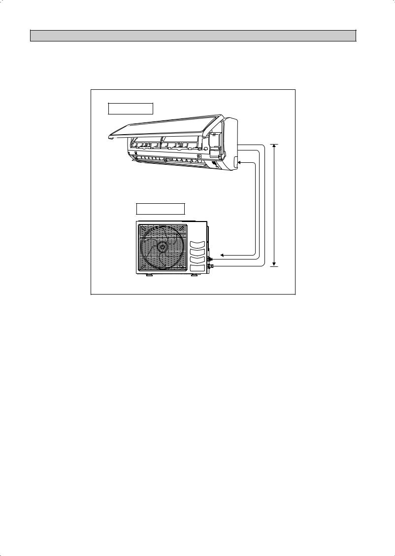
REFRIGERANT PIPING
Allowable Piping Length
If the pipe is too long, both the capacity and reliability of the unit will drop. As the number of bends increases, resistance to the flow of refrigerant system increases, thus lowering cooling capacity. As a result, the compressor may become defective. Always choose the shortest path and follow the recommendations as tabulated below:
Indoor unit |
|
L |
E |
Outdoor Unit |
|
Model |
Indoor |
(FTXN) |
25 |
|
35 |
50 |
|
60 |
Outdoor |
(RXN) |
25 |
|
35 |
50 |
|
60 |
|
|
|
|
||||||
Min. Allowable Length (L), m |
|
|
3 |
|
3 |
|||
|
|
|
|
|
|
|
|
|
Max. Allowable Length (L), m |
|
|
20 |
|
30 |
|||
|
|
|
|
|
|
|||
Max. Allowable Elevation (E), m |
|
|
10 |
|
10 |
|||
|
|
|
|
|
|
|||
Gas Pipe Size, mm/(in) |
|
|
9.52 (3/8") |
12.70 (1/2") |
|
15.88 (5/8") |
||
|
|
|
|
|
|
|||
Liquid Pipe Size, mm/(in) |
|
|
6.35 (1/4") |
6.35 (1/4") |
||||
*Be sure to add the proper amount of additional refrigerant. Failure to do so may result in reduced performance.
Remark: The refrigerant pre-charged in the outdoor unit is for piping length up to 7.5m.
Additional Charge
The refrigerant is pre-charged in the outdoor unit. If the piping length is less than 7.5m, then additional charge after vacuuming is not necessary. If the piping length is more than 7.5m, then use the additional charge value as indicated in the table.
Additional refrigerant charge [g] per additional 1m length as tabulated
Model |
Indoor |
(FTXN) |
25 |
35 |
50 |
60 |
|
|
|
|
|
|
|
||
Outdoor |
(RXN) |
25 |
35 |
50 |
60 |
||
|
|||||||
|
|
|
|
|
|
|
|
Additional charge [g/m] |
|
20 |
20 |
20 |
20 |
||
Example:
FTXN25 & RXN25 with 12m piping length, additional piping length is 4.5m. Thus, Additional charge = 4.5[m] x 20[g/m]
= 90.0[g]
1-10
REFRIGERANT PIPING
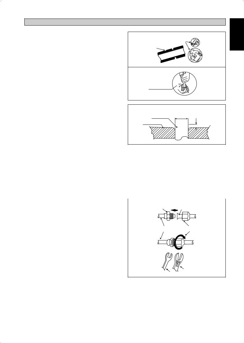
Piping Works And Flaring Technique
•Do not use contaminated or damaged copper tubing. If any piping, evaporator or condenser had been exposed or had been opened for 15 seconds or more, the system must be vacuumed. Generally do not remove plastic, rubber plugs and brass nuts from the valves, fittings, tubing and coils until it is ready to connect suction or liquid line into valves or fittings.
•If any brazing work is required, ensure that nitrogen gas is passed through coil and joints while the brazing work is being done. This will eliminate soot formation on the inside wall of copper tubings.
•Cut the pipe stages by stages, advancing the blade of pipe cutter slowly. Extra force and a deep cut will cause more distortion of pipe and therefore extra burr. See Figure I.
•Remove burrs from cut edges of the pipes with remover. See Figure II. Hold the pipe on top position and burr remover at lower position to prevent metal chips from entering the pipe. This will avoid unevenness on the flare faces which will cause gas leak.
•Insert the flare nuts, mounted on the connection parts of both the indoor unit and outdoor unit, into the copper pipes.
•The exact length of pipe protruding from the top surface of the swaging block is determined by the flaring tool. See Figure III.
•Fix the pipe firmly on the swaging block. Match the centers of both the swaging block and the flaring punch, then tighten the flaring punch fully.
•The refrigerant pipe connection are insulated by closed cell polyurethane.
Piping Connection To The Units
•Align the center of the piping and tighten the flare nut sufficiently with fingers. See Figure IV.
•Finally, tighten the flare nut with torque wrench until the wrench clicks.
•When tightening the flare nut with the torque wrench, ensure that the tightening direction follows the arrow indicated on the wrench.
•The refrigerant pipe connection are insulated by closed cell polyurethane.
Pipe Size, mm (in) |
Torque, Nm/(ft-lb) |
|
|
6.35 (1/4") |
18 (13.3) |
|
|
9.52 (3/8") |
42 (31.0) |
|
|
12.70 (1/2") |
55 (40.6) |
|
|
15.88 (5/8") |
65 (48.0) |
|
|
19.05 (3/4") |
78 (57.6) |
|
|
Figure I
Cutting Copper Tube
1/4t
Figure II
Remove Burr
Figure III
Copper Tube |
D |
Swaging Block |
<![if ! IE]> <![endif]>A |
|
Ø Tube, D |
|
A (mm) |
||||
Inch |
|
mm |
|
Imperial |
|
Rigid |
|
|
|
(Wing-nut Type) |
|
(Clutch Type) |
|
1/4" |
|
6.35 |
|
1.3 |
|
0.7 |
3/8" |
|
9.52 |
|
1.6 |
|
1.0 |
1/2" |
|
12.70 |
|
1.9 |
|
1.3 |
5/8" |
|
15.88 |
|
2.2 |
|
1.7 |
|
|
|
|
|
|
|
3/4" |
|
19.05 |
|
2.5 |
|
2.0 |
|
|
|
|
|
|
|
|
|
|
|
|
|
|
Figure IV |
Flare Joint |
Flared Tube |
|
|||
|
|
|
||||
Indoor Piping |
Flare Nut |
Torque Wrench
Spanner
<![endif]>English
1-11
ELECTRICAL WIRING CONNECTION
IMPORTANT : * The figures shown in the table are for information purpose only. They should be checked and selected to comply with the local/national codes of regulations. This is also subject to the type of installation and conductors used.
** The appropriate voltage range should be checked with label data on the unit.
Indoor Unit |
Interconnection |
Outdoor Unit |
|
|
|
Terminal Block |
cable |
Terminal Block |
|
|
|
1 |
|
|
1 |
|
|
2 |
|
|
2 |
|
|
SIG |
|
|
SIG |
|
|
N |
|
|
|
|
|
L |
|
Power |
Fuse / |
Main |
|
|
|
Supply |
Circuit |
Switch |
|
|
|
Cable |
Breaker |
L / L1 |
|
|
|
|
|
Power |
|
|
|
|
|
N / L2 |
Supply |
|
|
There must be an all pole disconnection |
|||
|
! in the supply mains with a contact |
||||
|
|
separation of at least 3mm. |
|
||
Model |
Indoor (FTXN) |
|
25 |
|
35 |
50 |
|
60 |
|
|
|
|
|
|
|
|
|
|
Outdoor (RXN) |
|
25 |
|
35 |
50 |
|
60 |
|
|
|
|
|
|
|
|
|
Voltage range** |
|
|
220-240V/~/50Hz + ! |
|
||||
Power supply cable size* |
mm2 |
|
1.5 |
2.5 |
|
|||
Number of conductors |
|
|
3 |
3 |
|
|||
Interconnection cable size* |
mm2 |
|
1.5 |
2.5 |
|
|||
Number of conductors |
|
|
4 |
4 |
|
|||
Recommended fuse /circuit breaker rating A |
|
16 |
20 |
|
||||
* If the length of the cable is more than 2m, use cable with bigger size.
•All wires must be firmly connected.
•Make sure all the wire do not touch the refrigerant pipings, compressor or any moving parts.
•The connecting wire between the indoor unit and the outdoor unit must be clamped by using provided cord anchorage.
•The power supply cord must be equivalent to H07RN-F which is the minimum requirement.
•Make sure no external pressure is applied to the terminal connectors and wires.
•Make sure all the covers are properly fixed to avoid any gap.
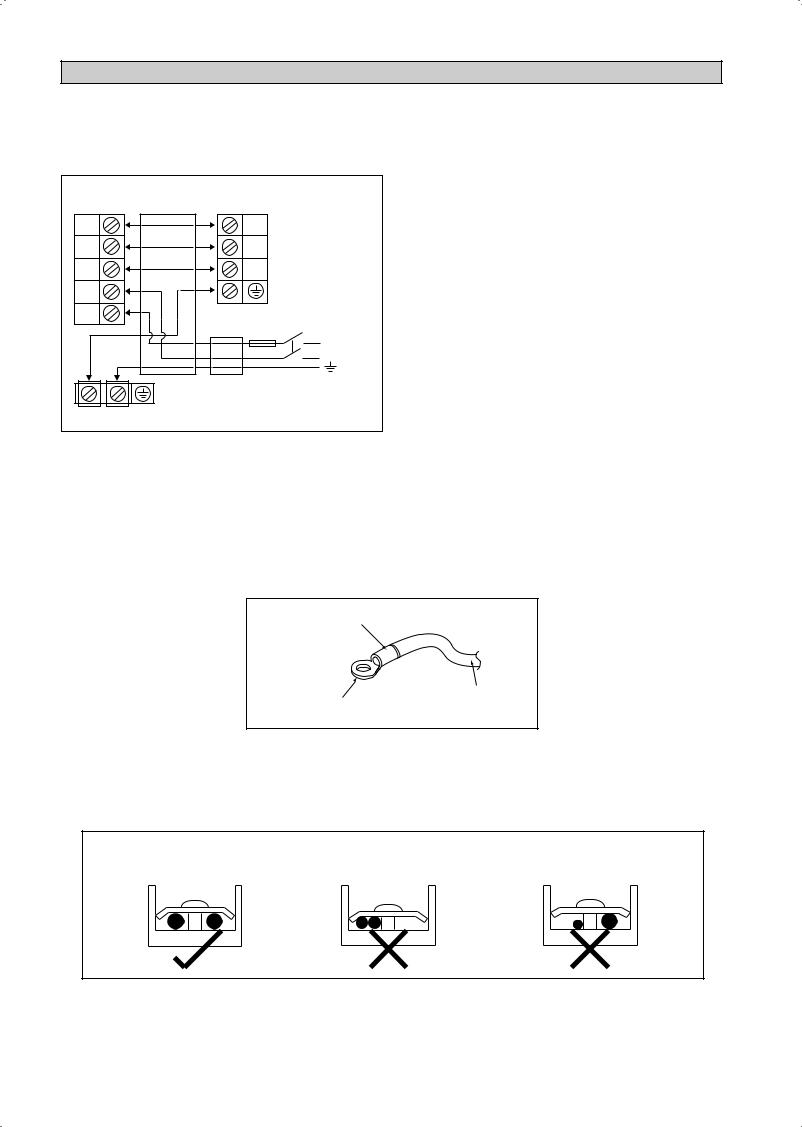
•Use round crimp-style terminal for connecting wires to the power supply terminal block. Connect the wires by matching to the indication on terminal block. (Refer to the wiring diagram attached on the unit).
Attach insulation sleeve
Electric wire
Round crimp-style terminal
•Used the correct screwdriver for terminal screws tightening. Unsuitable screwdrivers can damage the screw head.
•Over tightening can damage the terminal screws.
•Do not connect wire of different gauge to same terminal.
•Keep wiring in an orderly manner. Prevent the wiring from obstructing other parts and the terminal box cover.
Connect wires of the |
Do not connect wires of the |
Do not connect wires |
same gauge to both side. |
same gauge to one side. |
of different gauges. |
1-12
SPECIAL PRECAUTIONS WHEN DEALING WITH R410A UNIT
R410A is a new HFC refrigerant which does not damage the ozone layer. The working pressure of this new refrigerant is 1.6 times higher than conventional refrigerant (R22), thus proper installation/servicing is essential.
•Never use refrigerant other than R410Ain an air conditioner which is designed to operate with R410A.
•POE or PVE oil is used as lubricant for R410A compressor, which is different from the mineral oil used for R22 compressor. During installation or servicing, extra precaution must be taken not to expose the R410A system too long to moist air. Residual POE or PVE oil in the piping and components can absorb moisture from the air.
•To prevent mischarging, the diameter of the service port on the flare valve is different from that of R22.
•Use tools and materials exclusively for refrigerant R410A. Tools exclusively for R410A are manifold valve, charging hose, pressure gauge, gas leak detector, flare tools, torque wrench, vacuum pump and refrigerant cylinder.
•As an R410A air conditioner incurs higher pressure than R22 units, it is essential to choose the copper pipes correctly. Never use copper pipes thinner than 0.8mm even though they are available in the market.
•If the refrigerant gas leakage occurs during installation/ servicing, be sure to ventilate fully. If the refrigerant gas comes into contact with fire, a poisonous gas may occur.
•When installing or removing an air conditioner, do not allow air or moisture to remain in the refrigerant cycle.
VACUUMING AND CHARGING
Vacuuming is necessary to eliminate all moisture and air from the system.
Vacuuming The Piping And The Indoor Unit
Except for the outdoor unit which is pre-charged with refrigerant, the indoor unit and the refrigerant connection pipes must be air-purged because the air containing moisture that remains in the refrigerant cycle may cause malfunction of the compressor.
•Remove the caps from the valve and the service port.
•Connect the center of the charging gauge to the vacuum pump.
•Connect the charging gauge to the service port of the 3-way valve.
•Start the vacuum pump. Evacuate for approximately 30 minutes. The evacuation time varies with different vacuum pump capacity. Confirm that the charging gauge needle has moved towards -760mmHg.
Caution
•If the gauge needle does not move to -760mmHg, be sure to check for gas leaks (using the refrigerant detector) at flare type connection of the indoor and outdoor unit and repair the leak before proceeding to the next step.
•Close the valve of the changing gauge and stop the vacuum pump.
•On the outdoor unit, open the suction valve (3 way) and liquid valve (2 way) (in anti-clockwise direction) with 4mm key for hexagon sacked screw.
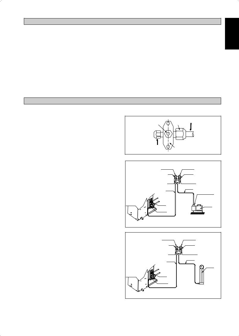
Charge Operation
This operation must be done by using a gas cylinder and a precise weighing machine. The additional charge is topped-up into the outdoor unit using the suction valve via the service port.
•Remove the service port cap.
•Connect the low pressure side of the charging gauge to the suction service port center of the cylinder tank and close the high pressure side of the gauge. Purge the air from the service hose.
•Start the air conditioner unit.
•Open the gas cylinder and low pressure charging valve.
•When the required refrigerant quantity is pumped into the unit, close the low pressure side and the gas cylinder valve.
•Disconnect the service hose from service port. Put back the service port cap.
Allen key |
Refrigerant Piping |
Flare nut |
Service Port
Outdoor Unit 3 ways valve
LOW PRESSURE GAUGE |
HIGH PRESSURE GAUGE |
|
-760mmHg |
GAUGE MANIFOLD |
|
HANDLE LO |
HANDLE HI (ALWAYS CLOSED) |
|
CHARGE HOSE |
CHARGE HOSE |
|
VACUUM PUMP |
||
|
||
|
ADAPTER FOR |
|
|
COUNTER FLOW |
|
|
PREVENTION |
|
LIQUID VALVE |
CHECK VALVE |
|
|
||
GAS VALVE |
|
|
(3-WAY) |
|
|
|
CONFIGURATION OFAIR |
|
|
PURGE BY CHARGING |
LOW PRESSURE GAUGE |
HIGH PRESSURE GAUGE |
-760mmHg |
GAUGE MANIFOLD |
HANDLE LO |
HANDLE HI (ALWAYS CLOSED) |
CHARGE HOSE |
CHARGE HOSE |
|
|
|
CHECK VALVE |
LIQUID VALVE |
|
GAS VALVE |
|
(3-WAY) |
|
|
CONFIGURATION OFAIR |
|
PURGE BY CHARGING |
<![endif]>English
1-13
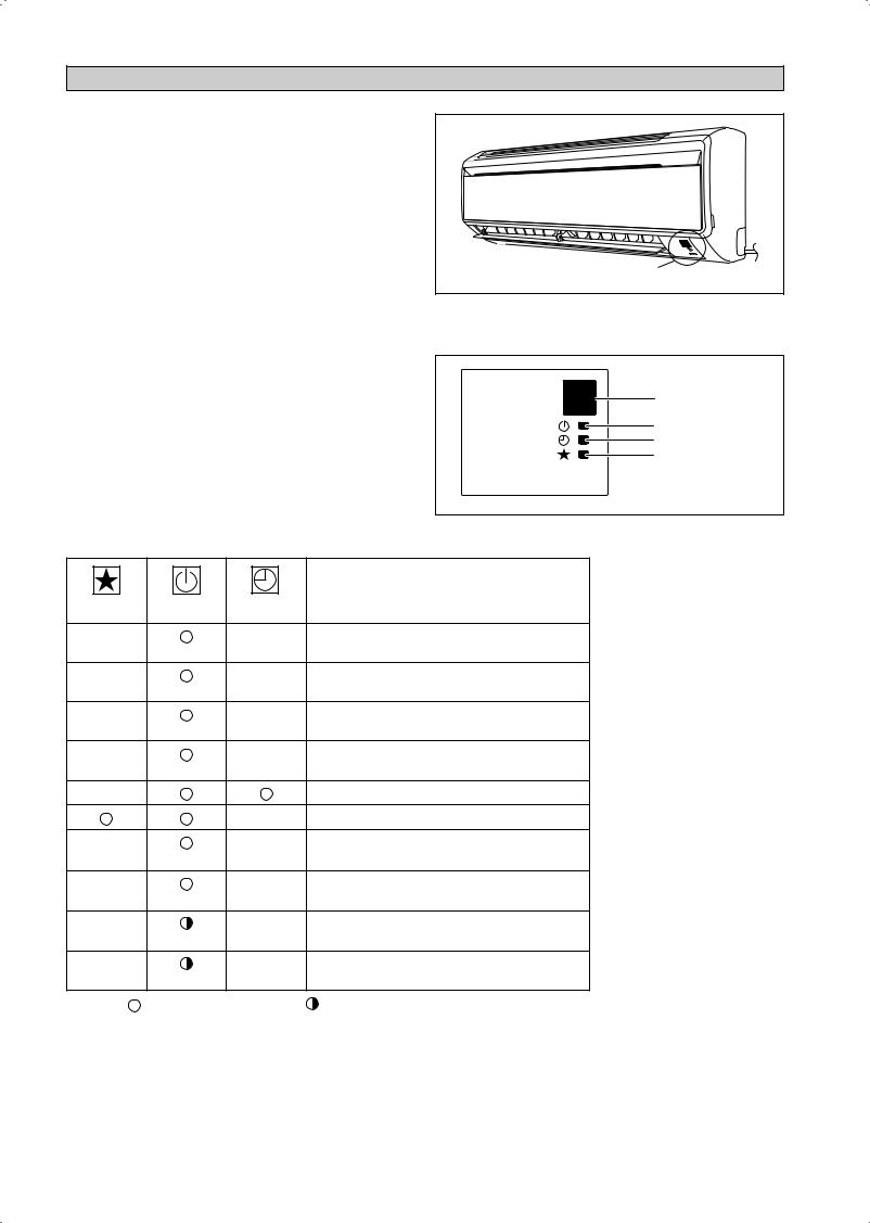
INDICATOR LIGHTS
IR Signal Receiver
When an infrared remote control operating signal has been transmitted, the signal receiver on the indoor unit will respond as below to confirm acceptance of the signal transmission.
ON to OFF |
1 Long Beep |
|
|
OFF to ON |
2 Short Beep |
Pump down / Cool force on |
|
|
|
Others |
1 Short Beep |
|
|
Cooling Unit/Heat Pump Unit
The table shows the LED indicator lights for the air conditioner unit under normal operation and fault conditions. The LED indicator lights are located at the side of the air conditioner unit.
The heat pump units are equipped with an “auto” mode sensor whereby it will provide reasonable room temperature by switching automatically to either “cool” or “heat” mode according to the temperature set by the user.
IR Receiver |
LED Indicator Lights for Cooling Unit/Heat Pump Unit
IR Receiver
Cool/Heat
Timer
Sleep
ON/OFF  ON/OFF switch
LED Indicator Lights: Normal Operation And Fault Conditions For Cooling/Heat Pump Unit
COOL/HEAT |
Operation |
|
|
(GREEN/RED) |
|
GREEN |
Cool mode |
|
|
RED |
Heat mode |
|
|
RED |
Auto mode in Heating operation |
|
|
GREEN |
Auto mode in Cooling operation |
|
|
|
Timer on |
|
Sleep mode on |
GREEN |
Fan mode on |
|
|
GREEN |
Dry mode on |
|
|
RED |
Defrost operation |
|
|
GREEN |
Unit error |
|
|
ON |
Blinking |
1-14
|
|
|
|
|
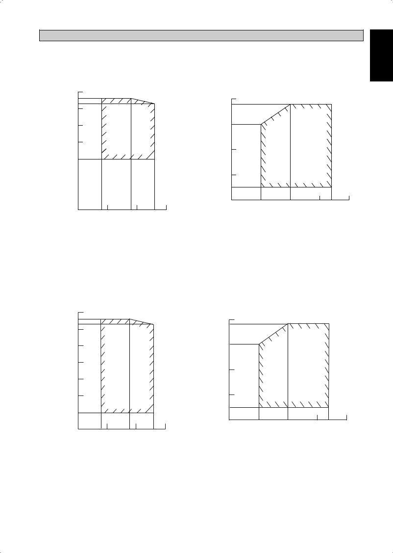
OPERATING RANGE |
|
|
|
|
|
|
Model: FTXN 25/35 |
RXN 25/35 |
|
|
|
|
|
|
|
|
||
|
|
COOLING |
|
|
|
|
HEATING |
|
|
|
|
|
50 |
|
|
|
|
|
|
|
|
|
|
|
46 |
|
|
|
|
20 |
|
|
|
|
|
|
43 |
|
|
|
|
18 |
|
|
|
|
|
| <![if ! IE]> <![endif]>CDB)˚(TEMPOUTDOOR |
40 |
|
|
|
<![if ! IE]> <![endif]>CWB)˚(TEMPOUTDOOR |
|
|
|
|
|
|
30 |
|
|
|
10 |
|
|
|
|
|
||
|
|
|
|
|
|
|
|
|
|
||
|
|
|
|
|
|
|
|
|
|
|
|
|
20 |
|
|
|
|
|
|
|
|
|
|
|
|
|
|
|
|
0 |
|
|
|
|
|
|
10 |
|
|
|
|
|
|
|
|
|
|
|
|
|
|
|
|
-10 |
|
|
|
|
|
|
|
|
|
|
|
-15 |
|
|
|
|
|
|
|
|
|
|
|
-20 |
|
|
|
|
|
|
0 |
|
|
|
|
10 |
15 |
20 |
25 |
27 |
30 |
|
|
|
|
|
|
|
|
|
|
|
|
|
10 |
14 15 |
19 20 |
23 |
25 |
|
|
|
|
|
|
|
INDOOR TEMP (˚CWB) |
|
|
|
INDOOR TEMP (˚CDB) |
|
|
|
|||
|
|
|
|
|
DB: Dry bulb WB: Wet bulb |
|
|
|
|
|
|
Model: FTXN 50/60 |
RXN 50/60 |
|
|
|
|
|
|
|
|
||
|
|
COOLING |
|
|
|
|
HEATING |
|
|
|
|
|
50 |
|
|
|
|
|
|
|
|
|
|
|
46 |
|
|
|
|
20 |
|
|
|
|
|
|
43 |
|
|
|
|
18 |
|
|
|
|
|
| <![if ! IE]> <![endif]>CDB)˚( |
40 |
|
|
|
<![if ! IE]> <![endif]>CWB)˚( |
|
|
|
|
|
|
30 |
|
|
|
10 |
|
|
|
|
|
||
| <![if ! IE]> <![endif]>TEMP |
|
|
|
<![if ! IE]> <![endif]>TEMP |
|
|
|
|
|
||
20 |
|
|
|
|
|
|
|
|
|
||
|
|
|
|
|
|
|
|
|
|
|
|
| <![if ! IE]> <![endif]>OUTDOOR |
|
|
|
|
<![if ! IE]> <![endif]>OUTDOOR |
0 |
|
|
|
|
|
10 |
|
|
|
|
|
|
|
|
|
||
|
|
|
|
|
|
|
|
|
|
|
|
|
0 |
|
|
|
|
-10 |
|
|
|
|
|
|
-10 |
|
|
|
|
-15 |
|
|
|
|
|
|
|
|
|
|
|
|
|
|
|
|
|
|
|
|
|
|
|
-20 |
|
|
|
|
|
|
-20 |
|
|
|
|
10 |
15 |
20 |
25 |
27 |
30 |
|
|
|
|
|
|
|
|
|
|
|
|
|
10 |
14 15 |
19 20 |
23 |
25 |
|
|
|
|
|
|
INDOOR TEMP (˚CWB) |
INDOOR TEMP (˚CDB) |
DB: Dry bulb |
WB: Wet bulb |
<![endif]>English
1-15
AIR FILTER
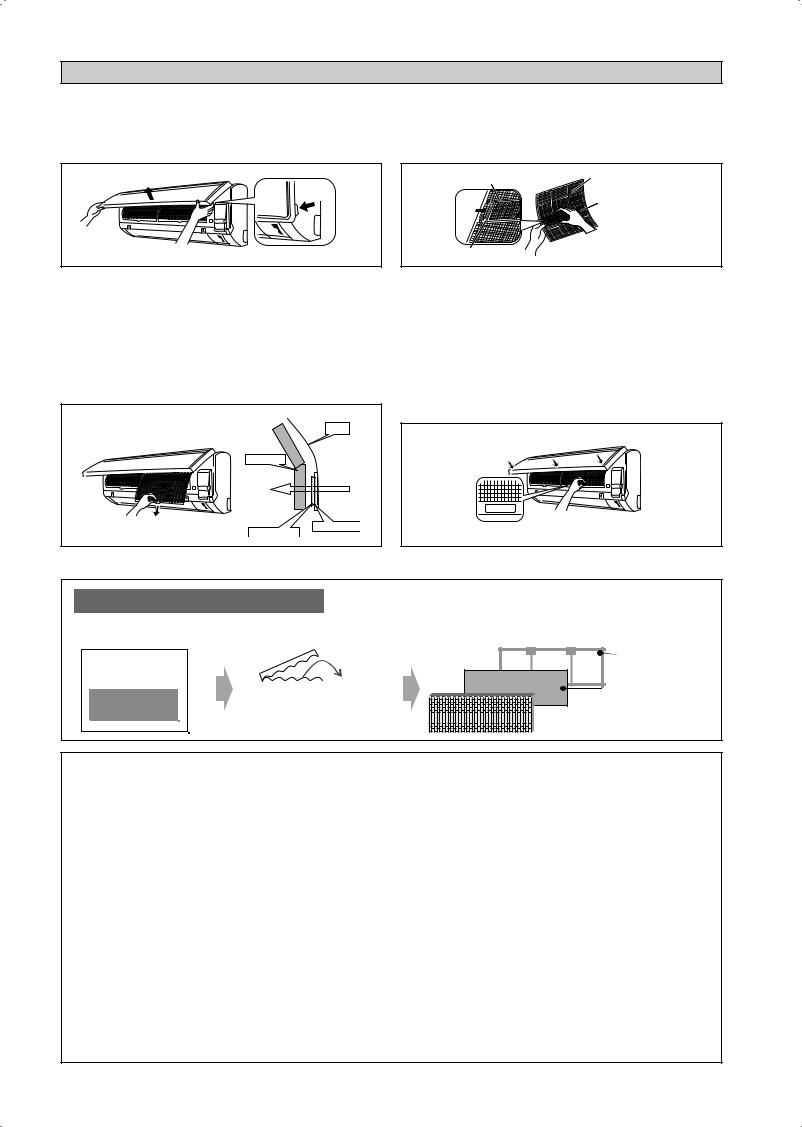
1.Open the front panel.
•Hold the panel at the recesses on the main unit
(2 recesses on right and left sides) and lift it until it stops.
Recess on main unit
4.Clean or replace each filter.
See figure.
•When shaking off remaining water, do not wring the filter.
Filter frame |
Air filter |
Bio filter with bacteriostatic, virustatic functions
Tab
2.Pull out the air filters.
•Push a little upwards the tab at the center of each air filter, then pull it down.
3.Take off the Bio filter with bacteriostatic, virustatic functions.
•Hold the recessed parts of the frame and unhook the four claws.
Titanium Apatite Filter (Bio Filter) |
Air Filter |
Attached Concept |
|
|
Heat exchanger |
|
Titanium Apatite Filter |
|
Bio Filter attached part |
5.Set the air filter and Bio filter with bacteriostatic, virustatic functions as they were and close the
front panel.
•Insert claws of the filters into slots of the front panel. Close the front panel slowly and push the panel at the 3 points. (1 on each side and 1 in the middle.)
•The air filter and Bio filter with bacteriostatic, virustatic functions have a symmetrical form in the horizontal direction.
FRONT
* Bio Filter and Titanium Apatite Filter are optional accessories.
Installation Procedure for Bio Filter
Bio Filter packs in a |
Take it out |
|||||
hermetically-sealed bag. |
at the time of installation. |
|||||
|
|
|
|
|
|
|
|
|
|
|
|
|
|
|
|
|
|
|
|
|
|
|
|
|
|
|
|
Slip the Filter in between Filter frame and
Titanium Apatite Filter.
Filter frame
Bio Filter |


 Titanium Apatite Filter
!CAUTION
•Please use this Bio Filter during dry season such as winter.
•Storage, handling and disposal methods.
•The lifetime of this Bio Filter is about a year after opening.
•In case you do not use this Bio Filter right away, please don’t place the Bio Filter in any place where it will be subjected to direct sunlight, high temperatures and/or high humidity.
•There can be slight differences between Bio Filter color because of the manufacturing reasons, there is no effect on the unit performance.
•Please open this bag right before you use it. Bio Filter should remain unopened and sealed in its packaging until right before usage. (It may cause performance deterioration or quality change.)
•To avoid danger of suffocation and any unexpected accident, please dispose the plastic bag immediately after you remove the Bio Filter. Keep out of reach of babies and children.
•If you keep this Bio Filter for a long time, please keep it unopened and store in a cool place avoiding direct sunlight.
•Please dispose the old Bio Filter as nonflammable garbage after use.
•Operation with dirty filters:
(1) cannot deodorize the air. |
(3) results in poor heating or cooling. |
(2) cannot clean the air. |
(4) may cause odour. |
•To order Bio Filter, contact the service shop where you bought the air conditioner.
1-16
|
|
SERVICE AND MAINTENANCE |
|
|
|
|
|
|
|
|
<![if ! IE]> <![endif]>English |
Service Parts |
|
Maintenance Procedures |
Period |
|
|
|
|
|
|||
|
|
|
|
|
|
Indoor air filter |
1. Remove any dust adhering to the filter by using a vacuum cleaner or wash |
At least once every |
|
|
|
|
|
in lukewarm water (below 40°C/104°F) with a neutral cleaning detergent. |
2 weeks. |
|
|
|
2. |
Rinse the filter well and dry before placing it back onto the unit. |
More frequently if |
|
|
|
3. |
Do not use gasoline, volatile substances or chemicals to clean the filter. |
necessary. |
|
|
|
|
|
|
|
|
Indoor unit |
1. Clean any dirt or dust on the grille or panel by wiping it with a soft cloth |
At least once every |
|
|
|
|
|
soaked in lukewarm water (below 40°C/104°F) and a neutral detergent |
2 weeks. |
|
|
|
|
solution. |
|
|
|
|
2. |
Do not use gasoline, volatile substances or chemicals to clean the indoor |
More frequently if |
|
|
|
|
unit. |
necessary. |
|
|
|
|
|
|
|
|
!CAUTION
•Avoid direct contact of any coil treatment cleaners on plastic part. This may cause plastic part to deform as a result of chemical reaction.
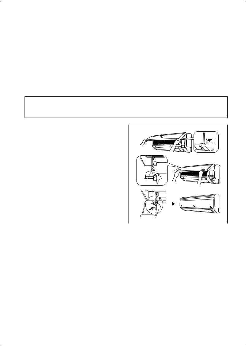
1.Open the front panel.
• Hold the panel at the recesses on the main unit |
Recess on |
(2 recesses on right and left sides) and lift it until it |
main unit |
|
|
stops. |
|
2.Remove the front panel.
•While lifting the front panel further, slide it to the right and pull it to the front side. The left rotating shaft is detached. Slide the right rotating shaft to the left and pull it to the front side to remove it.
3. Attach the front panel. |
Rotating |
shaft |
•Align the right and left rotating shafts of the front panel with the grooves and push them all the way in.
•Gently close the front panel. (Push both ends and the center on the front panel.)
1-17
!CAUTION
•Don’t touch the metal parts of the indoor unit. It may cause an injury.
•When removing or attaching the front panel, support the panel securely with hand to prevent it from falling.
•For cleaning, do not use hot water above 40°C, benzine, gasoline, thinner, nor other volatile oils, polishing compound, scrubbing brushes, nor other hand stuff.
•After cleaning, make sure that the front panel is securely fixed.
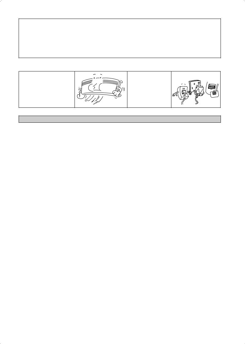
When The Unit Is Not To Be Used For An Extended Long Period Of Time
Operate the unit for 2 hours with the following setting.
Operating mode : cool Temperature : 30°C/86°F
Remove the power plug. If you are using an independent electric circuit for your unit, cut off the circuit.
Remove the batteries in the remote control.
TROUBLESHOOTING
For any enquiries on spare part, please contact your authorized dealer. When any malfunction of the air conditioner unit is noted, immediately switch off the power supply to the unit. Check the following fault conditions and causes for some simple troubleshooting tips.
|
Fault |
Causes / Action |
|
|
|
1. |
The compressor does not operate 3 minutes after the air |
– Protection against frequent starting. Wait for 3 to 4 minutes |
|
conditioner unit is started. |
for the compressor to start operating. |
|
|
|
2. |
The air conditioner unit does not operate. |
– Power failure, or the fuse needs to be replaced. |
|
|
– The power plug is disconnected. |
|
|
– It is possible that your delay timer has been set |
|
|
incorrectly. |
|
|
– If the fault persist after all these verifications, please |
|
|
contact the air conditioner unit installer. |
|
|
|
3. |
The air flow is too low. |
– The air filter is dirty. |
|
|
– The doors or windows are open. |
|
|
– The air suction and discharge are clogged. |
|
|
– The regulated temperature is not high enough. |
|
|
|
4. |
Discharge air flow has bad odour. |
– Odours may be caused by cigarettes, smoke particles, |
|
|
perfume etc. which might have adhered onto the coil. |
|
|
|
5. |
Condensation on the front air grille of the indoor unit. |
– This is caused by air humidity after an extended long |
|
|
period of operation. |
|
|
– The set temperature is too low, increase the temperature |
|
|
setting and operate the unit at high fan speed. |
|
|
|
6. |
Water flowing out from the air conditioner unit. |
– Switch off unit and call dealer. |
|
|
|
If the fault persists, please call your local dealer / serviceman.
1-18
CONTOUR ET DIMENSIONS
Unité Intérieure [FTXN]
LA MARQUE

 INDIQUE LA DIRECTION DES TUYAUX
A
ARRIÈRE |
ARRIÈRE |
GAUCHE
VUE DE DESSUS
<![if ! IE]><![endif]>B
BAS |
|
VOLET |
BAS |
|
|||
|
|
VIS FIXES DE LA GRILLE AVANT |
|
|
|
||
|
|
|
(INTÉRIEUR) |
DROITE
C
|
PLAQUE |
|
|
D’IDENTIFICATION |
|
SIGNAL DE |
<![if ! IE]> <![endif]>B |
|
RÉPARTITEUR |
||
RÉCEPTION |
||
AVEC BORNE |
||
|
||
|
DE MISE À LA |
|
UNITÉ INTÉRIEURE |
TERRE |
INTERRUPTEUR DE VUE LATÉRALE
SUR/ARRÊT
THERMISTOR DE TEMPÉRATURE
DE LA PIÈCE (INTÉRIEUR)
VUE DE DEVANT
REMARQUE : veuillez BASÉ SUR INSTALLATION réelle CONCEPTION DE LA PLAQUE DE L'UNITÉ DE PLAQUE D'INSTALLATION 25/35 RÉFÉRENCE DE DIMENSION À LA PAGE 1 &2.
«Points de fixation de la plaque de montage recommandés (5 points en tout)
D
<![if ! IE]><![endif]>F
<![if ! IE]><![endif]>B
Utilisez un mètre à ruban comme indiqué.
Placez l’extrémité du mètre à ruban sur Ñ
E
F
Trou percé dans le mur à Ø 65mm
| <![if ! IE]> <![endif]>G |
|
|
|
|
|
|
|
|
|
|
|
G |
|
|
|
|
|
|
|
|
|
|
|
|
|
|
|
||
H |
J |
L |
|
M |
|
|
|
|
K |
|
I |
|
|
|
|
|
|
A |
|
|
|
|
|
Position du tuyau |
|||||
|
|
|
|
|
|
|
|
|
|
|||||
|
|
|
|
|
|
|
|
|
|
|
||||
|
|
|
|
|
|
|
|
|
|
|
d’évacuation |
|
||
|
Extrémité du tuyau de liquide |
Extrémité du tuyau de gaz |
|
|
|
|
|
|||||||
|
|
|
PLAQUE D’INSTALLATION 25/35 |
|
|
|
|
|
|
|||||
Dimension |
A |
B |
C |
D |
E |
F |
G H |
I |
J |
K |
L M |
|||
Modèle |
||||||||||||||
|
|
|
|
|
|
|
|
|
|
|
|
|
||
25/35 |
800 |
288 |
204 |
166 |
184 |
42 |
46 |
55 |
56 |
154 |
182 |
263 |
52 |
|
Toutes les dimensions sont données en mm
2-1
<![endif]>Traduction des instructions d’origine Français
<![endif]>F
<![if ! IE]><![endif]>B
<![if ! IE]><![endif]>G
«Points de fixation de la plaque de montage recommandés (5 points en tout)
D E
H |
|
J |
|
|
|
|
|
|
|
|
|
|
|
|
|
|
|
|
|
|
|
|
|||
|
|
|
L |
|
|
|
M |
|
A |
K |
|
I |
|
|
|
Extrémité du tuyau de liquide |
|
|
|
|
|||||
|
|
|
Extrémité du tuyau de gaz |
|
||||||||
|
|
|
|
|
ALTERNATIVE PLAQUE D'INSTALLATION 25/35 |
|
||||||
<![endif]>F
Trou percé dans le mur à Ø 65mm
<![if ! IE]><![endif]>G
Position du tuyau d’évacuation
Toutes les dimensions sont données en mm
Modèle |
Dimension |
A |
B |
C |
D |
E |
F |
G |
H |
I |
J |
K |
L |
M |
|
||||||||||||||
|
|
|
|
|
|
|
|
|
|
|
|
|
|
|
|
|
|
|
|
|
|
|
|
|
|
|
|
|
|
25/35 |
|
800 |
288 |
204 |
104 |
141 |
30 |
46 |
55 |
56 |
153 |
181 |
207 |
52 |
|
|
|
|
|
|
|
|
|
|
|
|
|
|
|
«Points de fixation de la plaque de montage recommandés (7 points en tout)
D |
E |
| <![if ! IE]> <![endif]>F |
<![if ! IE]> <![endif]>F |
<![endif]>B
|
|
|
|
|
|
Trou percé dans le |
|
|
|
|
|
|
|
mur à Ø 65mm |
|
| <![if ! IE]> <![endif]>G |
|
|
|
|
|
<![if ! IE]> <![endif]>G |
|
H |
J |
Extrémité du tuyau de liquide |
Extrémité du tuyau de gaz |
K |
I |
Position du tuyau |
|
d’évacuation |
|||||||
|
|
L |
M |
|
|
||
|
|
|
|
|
|||
|
|
|
A |
|
|
|
|
|
|
|
PLAQUE D’INSTALLATION 50/60 |
|
|
|
Toutes les dimensions sont données en mm
Modèle |
Dimension |
A |
B |
C |
D |
E |
F |
G |
H |
I |
J |
K |
L |
M |
|
||||||||||||||
|
|
|
|
|
|
|
|
|
|
|
|
|
|
|
|
|
|
|
|
|
|
|
|
|
|
|
|
|
|
50/60 |
|
1065 |
310 |
228 |
190 |
173 |
61 |
40 |
45 |
48 |
91 |
219 |
580 |
45 |
|
|
|
|
|
|
|
|
|
|
|
|
|
|
|
2-2

Unité Extérieure [RXN]
|
|
|
Toutes les dimensions sont données en mm |
|
|
J |
H |
I |
|
|
<![if ! IE]> <![endif]>G |
|
<![if ! IE]> <![endif]>O |
|
|
|
|
<![if ! IE]> <![endif]>N |
|
|
|
|
<![if ! IE]> <![endif]>Q |
<![if ! IE]> <![endif]>Français |
|
F 2,0 D |
|
<![if ! IE]> <![endif]>P |
|
E |
B |
C |
|
<![endif]>M K L
<![if ! IE]><![endif]>A
Modèle |
Dimension |
A |
B |
C |
D |
E |
F |
G |
H |
|
|
I |
J |
K |
L |
M |
N |
O |
P |
Q |
|||||||
|
|
|
|||||||||||||||||||||||||
|
|
|
|
|
|
|
|
|
|
|
|
|
|
|
|
|
|
|
|
|
|
|
|
|
|
|
|
|
|
|
|
|
|
|
|
|
|
|
|
|
|
|
|
|
|
|
|
|
|
|
|
|
|||
25/35 |
|
|
550 |
658 |
51 |
|
11 |
273 |
|
16 |
14 |
470 |
|
96 |
|
93 |
94 |
60 |
14 |
133 |
8 |
10 |
299 |
||||
|
|
|
|
|
|
|
|
|
|
|
|
|
|
|
|
|
|
|
|
|
|
|
|
|
|
|
|
|
|
|
|
|
|
|
|
|
|
|
|
|
|
|
|
|
|
|
|
|
|
|
|
|
|
|
|
|
|
|
L |
|
|
K |
|
|
|
L |
|
|
|
|
|
|
Toutes les dimensions sont données en mm |
||||||||||
|
|
|
|
|
|
|
|
|
|
|
|
|
|
|
|
|
|
|
|
|
|
|
|
|
|
|
|
|
|
|
|
|
|
|
|
|
|
|
|
|
|
|
|
|
|
|
|
|
|
|
|
|
|
|
|
|
|
|
|
|
|
|
|
|
|
|
|
|
|
|
<![if ! IE]> <![endif]>N |
|
|
|
|
|
|
|
|
|
|
|
|
|
|
|
|
|
|
|
|
|
|
|
|
|
|
|
|
|
|
|
|
|
|
|
|
|
|
|
|
|
|
|
|
|
|
|
|
|
|
|
|
|
|
|
|
|
|
|
|
|
|
|
|
|
|
|
|
| <![if ! IE]> <![endif]>M |
| <![if ! IE]> <![endif]>Q |
|
|
|
|
A |
|
|
|
<![if ! IE]> <![endif]>N |
|
|
C |
|
|
|
|
|
3,0 |
O |
D |
|
|
|
|
|
<![if ! IE]> <![endif]>F |
|
G |
H |
|
|
|
|
|
|
|
|
|
|
|
|
|
|
|
||||
|
|
|
|
|
|
U |
|
|
|
|
|
|
|
|
|
|
|
|
|
|
|
|
|
|
|
|
|
|
|
|
|
|
|
V |
|
|
|
|
|
|
<![if ! IE]> <![endif]>E |
|
|
|
|
|
|
|
<![if ! IE]> <![endif]>B |
|
|
|
|
|
|
|
|
|
|
|
|
|
|
|
|
|
|
|
|
|
|
<![if ! IE]> <![endif]>S |
|
|
|
|
|
|
|
|
|
|
|
|
|
|
|
<![if ! IE]> <![endif]>R |
|
|
|
|
|
|
|
|
<![if ! IE]> <![endif]>P |
|
|
|
|
|
|
|
|
|
I |
J |
|
|
|
|
|
|
|
|
|
|
|
|
|
T |
|
|
|
|
|
|
Dimension |
B |
C |
D |
E |
F |
G H |
I |
J |
K |
L M N |
||||
Modèle |
|
A |
|||||||||||||
|
|
|
|
|
|
|
|
|
|
|
|
|
|
|
|
50/60 |
|
855 |
730 |
328 |
520 |
179 |
46 |
93 |
149 |
101 |
113 |
603 |
126 |
164 |
15 |
|
Dimension |
P |
Q |
R |
S |
T |
U |
V |
|
|
|
|
|
|
|
Modèle |
|
O |
|
|
|
|
|
|
|||||||
|
|
|
|
|
|
|
|
|
|
|
|
|
|
|
|
50/60 |
|
34 |
23 |
362 |
73 |
75 |
8 |
67 |
7 |
|
|
|
|
|
|
2-3
MANUEL D’INSTALLATION
Ce manuel fournit les procédures d’installation pour assurer le bon fonctionnement et la sécurité de cet appareil. Des ajustements peuvent être nécéssaires pour suivre les réglementations locales.
Avant d’installer et de faire fonctionner le climatiseur, lisez attentivement ce manuel et conservez le.
Cet appareil est destiné à être utilisé par des utilisateurs experts ou formés dans les magasins, dans l’industrie légère ou dans les fermes, ou pour un usage commercial par des personnes non spécialisées.
Cet appareil n’est pas destiné à être utilisé par des personnes, y compris les enfants, souffrant de capacités physiques, sensorielles ou mentales réduites, ou accusant un manque d’expérience et de connaissances, sauf si elles sont supervisées ou ont reçu des instructions concernant l’emploi de cet appareil d’une personne responsable de leur sécurité.
Les enfants doivent être supervisés pour s’assurer qu’ils ne jouent pas avec l’appareil.
PRÉCAUTIONS DE SÉCURITÉ
!ATTENTION
•L’installation et la maintenance doivent être exécutées par une personne qualifiée qui est familiarisée avec les lois et réglementations en vigueur, et aussi expérimentée dans ce type d’équipements.
•Tous les câblages doivent répondre aux réglementations électriques nationales.
•Avant de commencer le raccordement suivant le schéma électrique, s’assurer que la tension nominale de l’appareil corresponde bien à celle indiquée sur la plaque signalétique.
•L’unité doit être raccordée à la TERRE pour prévenir tous les risques possibles dûes à un défaut d’isolation.
•Aucun câble électrique ne doit toucher la tuyauterie d’eau ou des pièces mobiles des moteurs des ventilateurs.
•Avant l’installation ou l’entretien du climatiseur, s’assurer que l’appareil est éteint (OFF).
•Débrancher l’appareil du circuit d’alimentation secteur avant de procéder
àl’entretien du climatiseur.
•NE PAS retirer le câble d’alimentation électrique de la prise quand l’appareil est sous branché. Il peut en résulter des décharges électriques importantes susceptibles de provoquer un incendie.
•Les unités intérieures et extérieures, le cordon d’alimentation et le câblage de transmission doivent rester à une distance d’au moins 1m des téléviseurs et des radios, ce afin d’éviter les images déformées et les parasites. {En fonction du type et de la source des ondes électriques, des parasites peuvent être entendus même avec une distance supérieure à 1m}.
! AVERTISSEMENT
Vérifier les points suivants au cours de l’installation.
•Ne pas installer l’appareil où il peut se produire des fuites de gaz inflammable.
En cas de fuite et accumulation de gaz autour de l’appareil, il y a risque d’incendie.
•S’assurer que le tuyau d’évacuation du condensat est correctement branché.
Si le tuyau d’évacuation n’est pas correctement branché, les éventuelles fuites d’eau risquent de mouiller le mobilier.
•Ne pas surcharger l’unité (en fluide frigorigène).
Cet appareil est préchargé en usine.
Une charge trop importante risque de provoquer une surcharge électrique ou d’endommager le compresseur.
•S’assurer que le panneau supérieur de l’appareil est remis en place après l’installation ou l’entretien.
Avec un panneau mal fixé l’appareil va fonctionner bruyamment.
•Les bords coupants et les surfaces du refroidisseurtubulaire présentent un risque de blessure. Mieux vaut éviter le contact avec ces endroits.
•Avantdecouperl’alimentationélectrique,veilleràcequel’interrupteur
ON/OFF de la télécommande soit en position « OFF » afin d’éviter une mise en marche intempestive de l’appareil. Si l’interrupteur de la télécommande n’est pas en position « OFF », les ventilateurs de l’appareil se mettront en marche dès que l’alimentation électrique est rétablie. Il peut en résulter un danger pour le personnel d’entretien ou l’utilisateur.
•Ne pas installer les appareils à proximité ou près d’un passage de porte.
•Ne pas utiliser un appareil de chauffage trop près d’une unité de climatisation ou l’utiliser dans une pièce où, de l’huile minérale ou de la vapeur d’huile existent, cela peut faire fondre ou se déformer les pièces en plastique en raison de la chaleur excessive ou de réaction chimique.
•Lorsque l’appareil est utilisé dans la cuisine, le garder loin de la farine qui peut aller dans d’aspiration de l’appareil.
•Cet appareil n’est pas approprié pourune utilisation en usine lorsqu’un brouillard d’huile de coupe ou de la poudre de fer existe ou bien quand la tension fluctue grandement.
•Ne pas installer les unités à des endroits comme une source d’eau chaude ou une raffinerie de pétrole où des gaz sulfureux existent.
•S’assurer que la couleur des câbles de l’unité extérieure et les marquages de bornes sont identiques à ceux de l’unité intérieure.
•IMPORTANT:NEPASINSTALLEROUUTILISERLE CLIMATISEUR DANS UNE BUANDERIE.
•N’utilisez pas de câbles joints et torsadés pourl’alimentation électrique entrante.
•L’équipement n’est pas destiné à être utilisé dans une atmosphère potentiellement explosive.
AVIS
Instructions d’élimination
Cet appareil de conditionnement d’air porte le symbole ci-joint. Ce symbole signifie que les appareils électriques et électroniques doivent être éliminés séparément des ordures ménagères non triées.
N’essayez pas de démonter vous-même l’appareil : le démontage de l’appareil de conditionnement d’air ainsi que le traitement du réfrigérant, de l’huile et d’autres composants doivent être effectués par un installateur qualifié, en accord avec les réglementations locales et nationales en vigueur. 
Les appareils de conditionnement d’air doivent être traités dans des installations spécialisées de dépannage, réutilisation ou recyclage. En vous assurant  que cet appareil est éliminé correctement, vous contribuez à éviter les conséquences potentiellement néfastes sur l’environnement et la santé. Veuillez contacter votre installateur ou les autorités locales pour plus d’information.
Les piles de la télécommande doivent être enlevées et éliminées séparément, conformément aux réglementations locales et nationales en vigueur.
2-4

IMPORTANT
Information importante relative au réfrigérant utilisé
Ce produit contient des gaz fluorés à effet de serre encadrés par le protocole de Kyoto. Ne pas laisser les gaz s’échapper dans l’atmosphère.
Type de réfrigérant: R410A Valeur GWP (1) : 1975
(1) GWP = Potentiel De Réchauffement Global Prière de compléter à l’encre indélébile,
¢1 la charge de réfrigerant d’usine du produit,
¢2 la quantité de réfrigérant supplémentaire chargée sur place et
¢1 + 2 la charge de réfrigérant totale
sur l’étiquette de charge de réfrigérant fournie avec le produit.
L’étiquette complétée doit être apposée à proximité de l’orifice de recharge du produit (par ex. à l’intérieur du couvercle d’entretien).
1 charge de réfrigérant d’usine du produit : voir plaquette signalétique de l’unité (2)
2 quantité de réfrigérant supplémentaire chargée sur place
3 charge de réfrigérant totale
4 contient des gaz à effet de serre fluorés relevant du Protocole de Kyoto
5Unité extérieure
6cylindre de réfrigérant et collecteur de recharge
(2)Dans le cas de multiples systèmes intérieurs, seule 1 étiquette doit être apposée*, mentionnant la charge de réfrigérant d’usine totale de toutes les unités intérieures raccordées au système de réfrigérant.
Des inspections périodiques de fuites de réfrigérant peuvent être exigées en fonction de la législation européenne ou locale. Veuillez contacter votre distributeur local pour plus d’informations.
* sur l’unité extérieure
<![endif]>Français
2-5
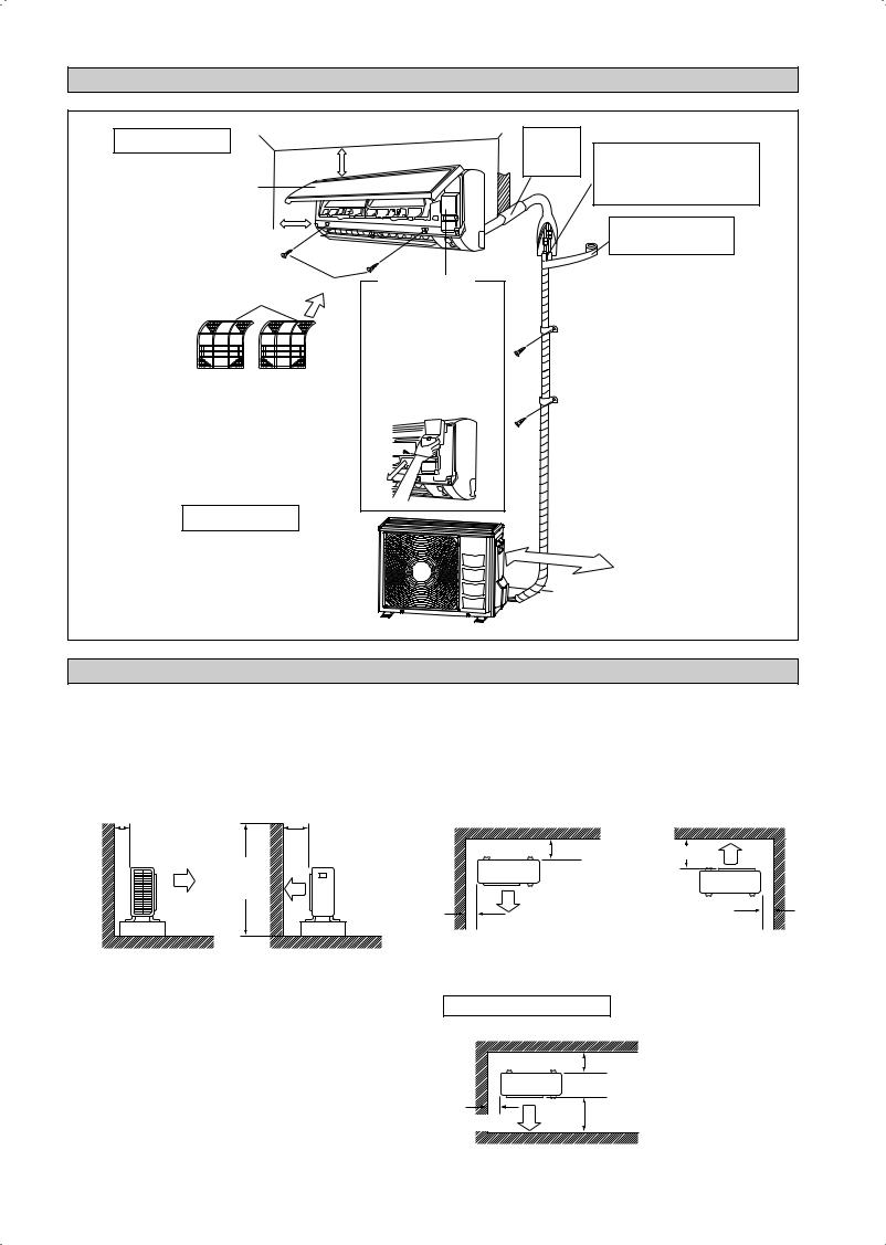
DIAGRAMME D’INSTALLATION
Unité Intérieure
30mm ou plus du plafond
Panneau avant
50mm ou plus des murs (des deux côtés)
M4 x 12L |
Couvercle de service |
Filtre à air |
ó Ouverture du couvercle de |
|
|
|
service |
|
Le couvercle de service est de |
|
type à ouverture/fermeture. |
ó Méthode d’ouverture
1) Enlevez les vis du couvercle de service.
2) Abaissez le couvercle de service en diagonale dans le sens de la flèche.
3) Tirez vers le bas.
Trou pour la tuyauterie calfaté avec du mastic.
Coupez le tuyau d’isolation thermique sur une longueur appropriée et enroulez-la de ruban en vous assurant qu’aucun espac en’est laissé à l’endroit de la coupe du tuyau d’isolation thermique.
Enroulez le tuyau d’isolation avec la bande de finition du bas jusqu’en haut.
Unité Extérieure
500mm des murs
INSTALLATION DE L’UNITÉ EXTÉRIEURE (RXN25/35)
•Si un mur ou tout autre obstacle se trouve sur le chemin du jet d’air d’admission ou de rejet de l’unité extérieure, suivre les directives d’installation ci-dessous.
•Pour l’un des modèles ci-dessous d’installation, la hauteur du mur sur le côté échappement doit être d’au moins 1200mm.
|
Mur face à un côté |
|
|
Mur face à deux côtés |
Plus de 50 |
Plus de 100 |
|||
1200 ou |
Plus de |
|
100 |
||
moins |
||
|
||
|
Plus de 50 |
Plus de 150 |
Plus de 50
Vue latérale |
|
Vue de dessus |
|
Mur face à trois côtés |
|
|
|
Plus de 150 |
|
Plus de 50 |
Plus de 300 |
|
|
|
|
|
Vue de dessus |
Unité : mm
2-6
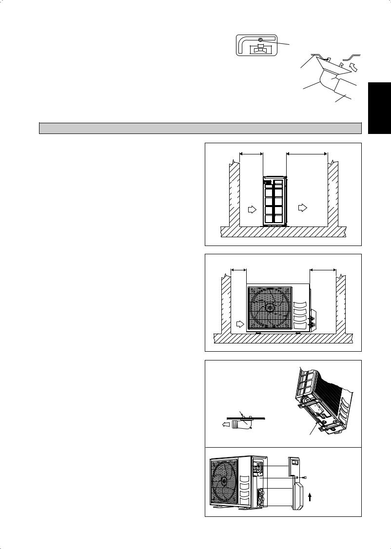
Travaux de vidange. (Unité De Pompe À Chaleur Seulement)
1)Utiliser le bouchon de vidange pour la vidange.
2)Si l’orifice de vidange est couvert par une base de montage ou une surface au sol, placer des cales de pieds supplémentaires d’au moins 30mm de hauteur sous les pieds de l’unité extérieure.
3)Dans les régions froides, n’utilisez pas de tuyau de vidange avec l’unité extérieure. (Sinon, l’eau de vidange peut se figer, altérant les performances du chauffage.)
Orifice d’eau de vidange
Châssis inférieur
Bouchon de vidange
Tuyau (disponible dans le commerce, diamètre intérieur de 16mm)
INSTALLATION DE L’UNITÉ EXTÉRIEURE (RXN50/60)
L’unité extérieure doit être installée de manière à ce qu’il n’y ait pas de reprise d’air chaud ou d’obstruction au débit régulier d’air. Veuillez respecter l’écartement d’installation illustré sur le diagramme. Choisir l’emplacement le plus frais possible, où l’admission d’air ne soit pas plus élevée que la température de l’air extérieure (se reporter à la plage de fonctionnement).
Dégagements minimum
Dimension |
A |
B |
C |
D |
|
|
|
|
|
Distance Minimume, mm |
300 |
1000 |
300 |
500 |
|
|
|
|
|
Remarque : En cas d’obstacles de part et d’autre de l’unité d’une hauteur supérieure à 2 mètres ou toute obstruction d’air sur le dessus de l’unité, augmenter sensiblement les dégagements minimum prévus.
Disposition Condensée De L’eau D’unité Extérieure (Unité De Pompe À Chaleur Seulement)
•Il y a 2 trous sur la base de l’unité extérieure pour que l’eau condensée sorte. Insérez le coude de drain à un des trous.
•Pour installer le coude de drain, première insertion une partie du crochet sur la base (partie A), tirer alors le coude de drain dans la direction montrée par la flèche tout en insérant l’autre partie à la base. Après installation, contrôle pour s’assurer que le coude de drain s’accrochent à la base fermement.
•Si l’unité est installée dans un neigeux et chily un secteur, l’eau condensée peut geler dans la base. Dans un tel cas, enlevez svp la prise au fond de l’unité pour lisser le drainage.
|
A |
B |
|
| <![if ! IE]> <![endif]>Obstacle |
<![if ! IE]> <![endif]>Reprise d’air |
<![if ! IE]> <![endif]>Refoulement d’air |
<![if ! IE]> <![endif]>Obstacle |
|
C |
|
D |
| <![if ! IE]> <![endif]>Obstacle |
<![if ! IE]> <![endif]>Reprise d’air |
<![if ! IE]> <![endif]>Accès de service |
<![if ! IE]> <![endif]>Obstacle |
PRISE
A
BASE
 VIDANGEZ LE COUDE
VIDANGEZ LE COUDE 
Veuillez enlever le plat latéral en reliant  lat uyauterie et en reliant la corde
POUSSER ET TIRER VERS LE HAUT
<![endif]>Français
2-7
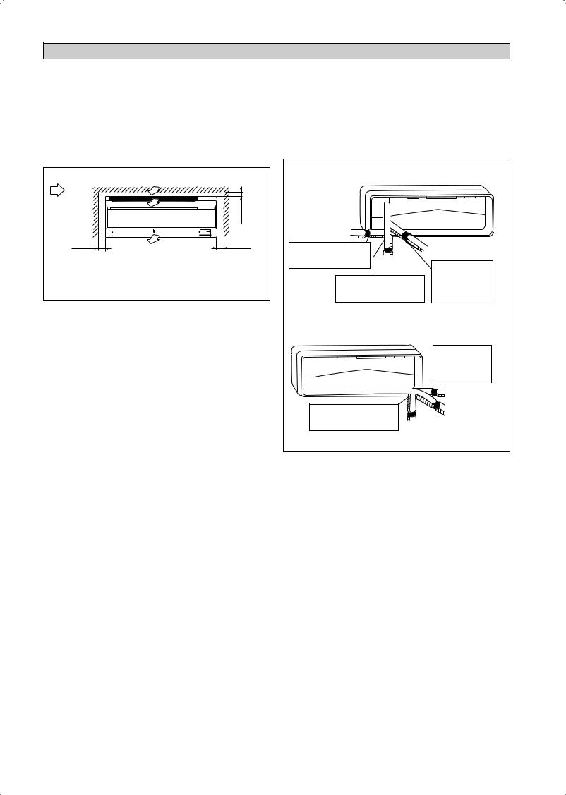
INSTALLATION DE L’UNITÉ INTÉRIEURE
Installer l’unité intérieure de traitement d’air de façon à ce qu’il n’y ait aucun obstacle sur la circulation de l’air (risque de recyclage de l’air refroidi au refoulement de l’unité et l’air à l’entrée). Veuillez respecter l’écartement d’installation illustré sur le diagramme. Ne pas exposer l’unité intérieure à l’influence directe de l’éclairage. L’emplacement de l’unité, doit permettre une évacuation aisée des condensats, et permettre une evacuation aisee des condensats, et doit être suffisamment loin des portes.
Flux d’air |
<![if ! IE]> <![endif]>mini 30 (Espace pour performance) |
(Intérieur) |
|
|
|
mini 50 |
mini 50 |
(Espace pour |
Espace nécessaire |
(Espace pour |
|
entretien) |
entretien) |
|
Toutes les dimensions sont données en mm |
La tuyauterie de réfrigérant peut être dirigée vers l’appareil de plusieurs façons (sur la gauche ou la droite, depuis l’arrière de l’appareil), par le biais des orifices défonçables situés sur l’enveloppe de l’appareil. Cintrer les tuyaux avec précaution afin de les aligner avec les orifices. Pour les sorties latérale et inférieure, maintenir le bas de la tuyauterie et la positionner dans la bonne direction. Le flexible d’évacuation des condensats peut être fixé aux tuyaux.
Tuyauterie sur le côté droit, à l’arrière droite ou en bas à droite
Tuyautage du côté droit |
|
|
|
Retirez le couvercle du port |
|
Tuyautage du côté arrière droit |
|
du tube ici pour le tuyautage |
Tuyautage du côté |
|
|
du côté droit |
Attachez ensemble |
||
inférieur droit |
|||
|
|||
Retirez le couvercle du port du |
le tube de réfrigérant |
||
avec le tuyau de |
|||
tube ici pour le tuyautage du côté |
vidange avec du ruban |
||
inférieur droit |
|
isolant. |
|
Tuyauterie sur le côté gauche, à l’arrière gauche ou en bas à gauche
|
Retirez le couvercle |
|
|
du port du tube ici |
|
|
pour le tuyautage du |
|
|
côté gauche |
|
|
Tuyautage du côté |
|
|
gauche |
|
Retirez le couvercle du port du |
Tuyautage du côté |
|
tube ici pour le tuyautage du côté |
||
arrière gauche |
||
arrière gauche |
||
|
||
Tuyautage du côté inférieur gauche |
||
2-8
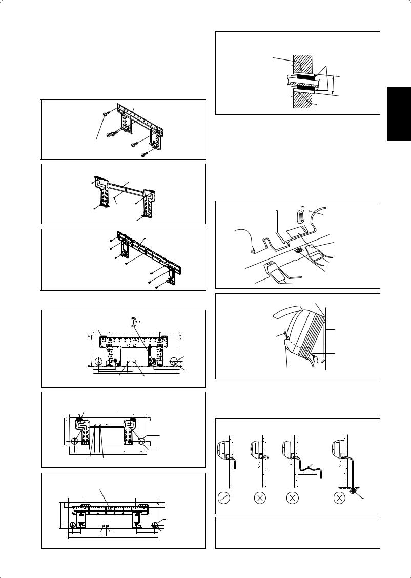
Montage De La Platine Support
S’assurrer que le mur de support soit suffisamment résistant, pour supporter le poids de l’unité et éviter toutes vibrations. Selon la composition du mur, utiliser des vis chevilles appropriées pour la fixation de la platine support.
Utilisez l’indicateur de niveau pour le montage horizontal, et fixez-le avec 5 vis adaptées pour FTXN25/35 et 7 vis adaptées pour FTXN50/60.
Dans le cas de sortie arrière des tuyauteries, percer le trou Ø 65mm pour les canalisations à l’aide d’une scie cloche. Le trou aura une légère pente vers l’unité extérieure (voir figure).
FTXN 25/35 |
Plaque de montage |
Vis de fixation de la plaque de montage
FTXN 25/35 (ALTERNATIVE PLAQUE D'INSTALLATION)
Plaque de montage
Vis de fixation de la plaque de montage
FTXN 50/60
Plaque de montage
Vis de fixation de la plaque de montage 
Point De Retenue Et Dimensions Recommandés Pour La Platine De Montage
FTXN 25/35
Utilisez un mètre à ruban comme indiqué. « Points de fixation de la plaque de montage recommandés  Placez l’extrémité du mètre à ruban sur Ñ
(5 points en tout)
|
166 |
|
|
184 |
|
|
| <![if ! IE]> <![endif]>42,2 |
|
|
|
|
|
<![if ! IE]> <![endif]>42,2 |
| <![if ! IE]> <![endif]>288 |
|
|
|
|
|
|
|
|
|
|
|
|
Trou percé dans le |
|
|
|
|
|
|
mur à Ø 65mm |
| <![if ! IE]> <![endif]>45,9 |
153,8 |
|
|
181,7 |
55,5 |
<![if ! IE]> <![endif]>45,9 |
54,5 |
263 |
51,9 800 |
Position du tuyau |
|||
|
|
|
|
|||
Extrémité du tuyau de liquide |
|
Extrémité du tuyau de gaz |
|
d’évacuation |
||
|
|
|
||||
Toutes les dimensions sont données en mm
FTXN 25/35 (ALTERNATIVE PLAQUE D'INSTALLATION)
«Points de fixation de la plaque de montage recommandés (5 points en tout)
104 |
|
|
|
141 |
| <![if ! IE]> <![endif]>30 |
|
|
|
<![if ! IE]> <![endif]>30 |
| <![if ! IE]> <![endif]>288 |
|
|
|
Trou percé dans le mur à Ø 65mm |
|
|
|
|
|
| <![if ! IE]> <![endif]>46 |
|
|
|
<![if ! IE]> <![endif]>46 |
|
153 |
|
|
Position du tuyau d’évacuation |
55 |
207 |
52 |
181 |
56 |
|
|
|
800 |
|
Extrémité du tuyau de liquide |
|
Extrémité du tuyau de gaz |
|
|
Toutes les dimensions sont données en mm
FTXN 50/60
«Points de fixation de la plaque de montage recommandés (7 points en tout)
190 |
|
173 |
|
|
| <![if ! IE]> <![endif]>61 |
|
|
|
<![if ! IE]> <![endif]>61 |
| <![if ! IE]> <![endif]>310 |
|
|
|
Trou percé dans le |
|
|
|
|
|
|
|
|
|
mur à Ø 65mm |
| <![if ! IE]> <![endif]>40 |
|
|
|
<![if ! IE]> <![endif]>40 |
45 91 Extrémitédutuyaudeliquide |
Extrémitédutuyaudegaz |
219 |
48 |
Position du tuyau |
580 |
45 1065 |
|
|
d’évacuation |
Toutes les dimensions sont données en mm
Trou Avec Perceuse En Cône
Intérieur 
 Tube noyé dans le mur
(À se procurer sur place)
Couvercle de trou de mur (À se procurer sur place)
Extérieur
Calfatage
Ø 65
Tube noyé dans le mur (À se procurer sur place)
Mise En Place De L’unite De La Platine Support
Positionner dans un premier temps l’unité intérieure sur la languette d’accrochage supérieure de support. Pour vous assurer que les crochets sont correctement installés sur la plaque d’installation, essayez de les faire légèrement bouger de gauche à droite.
Comment Fixer L’unité Interne
Accrochez les griffes de la structure inférieure à la plaque de montage.
Comment Démonter L’unité Interne
Soulevez la zone marquée d’un repère (au bas de la grille avant) pour libérer les griffes.
Plaque de montage
Attache
Châssis inférieur
Grille frontale |
Repère (à l’arrière) |
Accrochez les crochets de l’appareil intérieur ici.
Quand vous dénudez en avance |
Plaque de montage |
|
les fils d’interconnexion, |
||
|
||
recouvrez les extrémités des |
|
|
fils avec du ruban isolant. |
Fils |
|
|
||
|
d’interconnexion |
Guide de fil
Évacuation Des Condensats
Le tube d’évacuation des condensats de l’unité devra être, dans la mesure du possible, dirigé vers la sortie arriere des tuyauteries a travers le mur de support. Evitez les situations susceptibles de causer une fuite d’eau.
Drainage De L’eau
|
|
Rétention |
|
Evacuation |
|
|
de l’eau |
|
|
|
|
|
|
d’eau de |
|
Fuite |
Fuite |
Fuite |
condensation |
|
d’eau |
d’eau |
d’eau |
plongé dans |
|
|
|
|
l’eau |
|
|
|
|
Drainage |
Correct |
Mauvais |
Mauvais |
Mauvais |
|
!AVERTISSEMENT
•N’installez pas l’unité, intérieure comme extérieure, à une altitude supérieure à 2000m.
<![endif]>Français
2-9
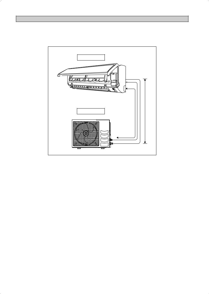
RACCORDEMENTS DES TUYAUTERIES
Longueur admissible de tuyauterie
Une tuyauterie trop longue va diminuer à la fois la performance et la fiabilité de lʼappareil. Plus le nombre dʼangles est grand, plus le système de réfrigérant résiste au flux, ce qui affaiblit la capacité de refroidissement. En conséquence, le compresseur peut connaître des défectuosités. Choisissez toujours le chemin le plus court et suivez les recommandations données dans le tableau ci-dessous:
Unité intérieure |
|
L |
E |
Unité Extérieure |
|
Modèle |
Intérieure |
(FTXN) |
25 |
|
35 |
50 |
|
60 |
|
|
|
|
|
|
|
|
|
Extérieure |
(RXN) |
25 |
|
35 |
50 |
|
60 |
|
|
|
|
||||||
|
|
|
|
|
|
|
|
|
Longueur minimum admissible (L), m |
|
3 |
|
3 |
||||
Longueur maximale autorisée (L), m |
|
20 |
|
30 |
||||
Élévation Admise Max (E), m |
|
|
10 |
|
10 |
|||
|
|
|
|
|
||||
Racc. Tube Aspiration, mm / (pouces) |
|
9,52 (3/8") |
12,70 (1/2") |
|
15,88 (5/8") |
|||
|
|
|
|
|
|
|||
Racc. Tube Liquide, mm / (pouces) |
|
|
6,35 (1/4") |
6,35 (1/4") |
||||
|
|
|
|
|
|
|
|
|
*Assurez-vous d’ajouter la quantité correcte de réfrigérant additionnel. Sinon, cela pourrait conduire à une réduction de sperformances.
Remarque : La charge complète de gaz se trouve dans l’unité extérieure jusqe’à une longueur nominale de 7,5 mètres aucun complément en réfrigérant n’est nécéssaire.
Charge additionnelle
Le réfrigérant est pré-chargé dans l’unité extérieure. Si la longueur des tuyaux est inférieure à 7,5m, alors la charge supplémentaire après un tirage n’est pas nécessaire. Si la longueur de la tuyauterie est supérieure à 7,5m, alors utiliser la valeur de charge supplémentaire comme indiqué dans le tableau.
Charge de réfrigérant supplémentaire [g] par longueur supplémentaire de 1m indiquée dans le tableau
Modèle |
Intérieure |
(FTXN) |
25 |
35 |
50 |
60 |
|
Extérieure |
(RXN) |
25 |
35 |
50 |
60 |
||
|
|||||||
|
|
|
|
|
|
|
|
Charge additionnelle [g/m] |
|
20 |
20 |
20 |
20 |
||
|
|
|
|
|
|
|
|
Exemple : |
|
|
|
|
|
||
FTXN25 & RXN25 avec une longueur de tuyauterie de 12m la longueur de tuyauterie supplémentaire est de 4,5m. Ainsi, Charge additionnelle = 4,5[m] x 20[g/m]
= 90,0[g]
2-10
 Loading...