


 Loading...
Daikin FFA25A2VEB, FFA35A2VEB, FFA50A2VEB, FFA60A2VEB, FFA25A2VEB9 Installer reference guide
...Installer and user
reference guide
Split system air conditioners
FFA25A2VEB
FFA35A2VEB
FFA50A2VEB
FFA60A2VEB
FFA25A2VEB9 |
|
|
FFA35A2VEB9 |
Installer and user reference guide |
|
|
||
FFA50A2VEB9 |
English |
|
FFA60A2VEB9 |
Split system air conditioners |
|

Table of contents
Table of contents
1 General safety precautions |
3 |
||
1.1 |
About the documentation .......................................................... |
3 |
|
|
1.1.1 Meaning of warnings and symbols.............................. |
3 |
|
1.2 |
For the user ............................................................................... |
3 |
|
1.3 |
For the installer.......................................................................... |
3 |
|
|
1.3.1 |
General ....................................................................... |
3 |
|
1.3.2 |
Installation site ............................................................ |
4 |
|
1.3.3 |
Refrigerant .................................................................. |
5 |
|
1.3.4 |
Brine............................................................................ |
6 |
|
1.3.5 |
Water .......................................................................... |
6 |
|
1.3.6 |
Electrical ..................................................................... |
6 |
|
7.1 |
Field settings .............................................................................. |
18 |
8 |
Commissioning |
19 |
|
|
8.1 |
Overview: Commissioning.......................................................... |
19 |
|
8.2 |
Precautions when commissioning .............................................. |
19 |
|
8.3 |
Checklist before commissioning................................................. |
19 |
|
8.4 |
To perform a test run.................................................................. |
20 |
|
8.5 |
Error codes when performing a test run ..................................... |
21 |
9 |
Hand-over to the user |
21 |
|
10 |
Disposal |
21 |
|
11 |
Technical data |
21 |
|
|
11.1 |
Piping diagram: Indoor unit ........................................................ |
21 |
|
11.2 |
Wiring diagram ........................................................................... |
22 |
|
|
|
2 |
About the documentation |
7 |
|
For the user |
23 |
|
|||
|
|
|
|
2.1 |
About this document |
7 |
|
|
||||
|
|
|
|
|
|
|
|
|
||||
|
|
|
|
2.2 |
..........................Installer and user reference guide at a glance |
7 |
|
12 About the system |
23 |
|
||
|
|
|
|
|
|
|
|
|
|
|||
|
|
|
|
|
|
|
|
12.1 |
System layout............................................................................. |
23 |
|
|
|
|
|
|
|
|
|
|
12.2 |
User interface |
23 |
|
|
|
|
|
For the installer |
8 |
|
|||||||
|
|
|
|
13 Before operation |
23 |
|
||||||
|
|
|
3 |
About the box |
8 |
|
|
|||||
|
|
|
|
14 Operation |
23 |
|
||||||
|
|
|
|
3.1 |
Overview: About the box ........................................................... |
8 |
|
|
||||
|
|
|
|
3.2 |
Indoor unit ................................................................................. |
8 |
14.1 |
Operation range ......................................................................... |
23 |
|
||
|
|
|
|
|
3.2.1 |
To unpack and handle the unit.................................... |
8 |
14.2 |
Operating the system ................................................................. |
24 |
|
|
|
|
|
|
|
3.2.2 |
To remove the accessories from the indoor unit......... |
8 |
|
|
14.2.1 About operating the system ......................................... |
24 |
|
|
|
|
4 About the units and options |
9 |
|
|
14.2.2 About cooling, heating, fan only, and automatic |
|
|
|||
|
|
|
|
|
operation ...................................................................... |
24 |
|
|||||
|
|
|
|
4.1 |
Overview: About the units and options...................................... |
9 |
|
|
14.2.3 About the heating operation......................................... |
24 |
|
|
|
|
|
|
4.2 |
Identification .............................................................................. |
9 |
|
|
14.2.4 To operate the system ................................................. |
24 |
|
|
|
|
|
|
|
4.2.1 |
Identification label: Indoor unit .................................... |
9 |
|
14.3 Using the dry program................................................................ |
25 |
|
|
|
|
|
|
4.3 |
About the indoor unit ................................................................. |
9 |
|
|
14.3.1 About the dry program ................................................. |
25 |
|
|
|
|
|
|
4.4 |
System layout............................................................................ |
10 |
|
|
14.3.2 To use the dry program................................................ |
25 |
|
|
|
|
|
|
4.5 |
Combining units and options ..................................................... |
10 |
|
14.4 Adjusting the air flow direction.................................................... |
25 |
|
||
|
|
|
|
|
4.5.1 |
Possible options for the indoor unit............................. |
10 |
|
|
14.4.1 About the air flow flap .................................................. |
25 |
|
|
|
|
5 |
Preparation |
10 |
|
15 Energy saving and optimum operation |
25 |
|
|||
|
|
|
|
5.1 |
Overview: Preparation............................................................... |
10 |
|
16 Maintenance and service |
25 |
|
||
|
|
|
|
5.2 |
Preparing the installation site .................................................... |
10 |
|
|
||||
|
|
|
|
|
5.2.1 |
Installation site requirements of the indoor unit |
10 |
|
16.1 Cleaning the air filter, suction grille, air outlet and outside |
|
|
|
|
|
|
|
|
|
|
panels |
26 |
|
|||
|
|
|
|
5.3 |
Preparing refrigerant piping |
11 |
|
|
|
|||
|
|
|
|
|
|
16.1.1 To clean the air filter |
26 |
|
||||
|
|
|
|
|
5.3.1 |
Refrigerant piping requirements |
11 |
|
|
|
||
|
|
|
|
|
|
|
16.1.2 To clean the suction grille |
26 |
|
|||
|
|
|
|
|
5.3.2 |
Refrigerant piping insulation |
11 |
|
|
|
||
|
|
|
|
|
|
|
16.1.3 To clean the air outlet and outside panels |
27 |
|
|||
|
|
|
|
5.4 |
Preparing electrical wiring |
11 |
|
|
|
|||
|
|
|
|
|
16.2 Maintenance after a long stop period |
27 |
|
|||||
|
|
|
|
|
5.4.1 |
About preparing electrical wiring |
11 |
|
|
|||
|
|
|
|
|
|
16.3 Maintenance before a long stop period |
27 |
|
||||
|
|
|
6 |
Installation |
12 |
|
|
|||||
|
|
|
16.4 |
About the refrigerant................................................................... |
27 |
|
||||||
|
|
|
|
6.1 |
Overview: Installation ................................................................ |
12 |
|
16.5 After-sales service and warranty ................................................ |
28 |
|
||
|
|
|
|
6.2 |
Mounting the indoor unit............................................................ |
12 |
|
|
16.5.1 Warranty period ........................................................... |
28 |
|
|
|
|
|
|
|
6.2.1 |
Precautions when mounting the indoor unit................ |
12 |
|
|
16.5.2 Recommended maintenance and inspection............... |
28 |
|
|
|
|
|
|
6.2.2 |
Guidelines when installing the indoor unit................... |
12 |
|
|
16.5.3 Recommended maintenance and inspection cycles.... |
28 |
|
|
|
|
|
|
6.2.3 |
Guidelines when installing the drain piping................. |
13 |
|
|
16.5.4 Shortened maintenance and replacement cycles ........ |
28 |
|
|
|
|
|
6.3 |
Connecting the refrigerant piping .............................................. |
15 |
|
17 Troubleshooting |
28 |
|
||
|
|
|
|
|
6.3.1 |
About connecting the refrigerant piping |
15 |
|
|
|||
|
|
|
|
|
|
17.1 Symptoms that are NOT system malfunctions |
29 |
|
||||
|
|
|
|
|
6.3.2 |
Precautions when connecting the refrigerant piping |
15 |
|
|
|||
|
|
|
|
|
|
|
17.1.1 Symptom: The system does not operate |
29 |
|
|||
|
|
|
|
|
6.3.3 |
Guidelines when connecting the refrigerant piping |
15 |
|
|
|
||
|
|
|
|
|
|
|
17.1.2 Symptom: The fan speed does not correspond to the |
|
|
|||
|
|
|
|
|
6.3.4 |
Pipe bending guidelines |
15 |
|
|
|
|
|
|
|
|
|
|
|
|
setting |
29 |
|
|||
|
|
|
|
|
6.3.5 |
To flare the pipe end |
16 |
|
|
|
||
|
|
|
|
|
|
|
17.1.3 Symptom: The fan direction does not correspond to |
|
|
|||
|
|
|
|
|
6.3.6 |
To connect the refrigerant piping to the indoor unit |
16 |
|
|
|
|
|
|
|
|
|
|
|
|
the setting |
29 |
|
|||
|
|
|
|
|
6.3.7 |
To check for leaks |
16 |
|
|
|
||
|
|
|
|
|
|
|
17.1.4 Symptom: White mist comes out of a unit (Indoor |
|
|
|||
|
|
|
|
6.4 |
Connecting the electrical wiring |
16 |
|
|
|
|
||
|
|
|
|
|
|
unit) .............................................................................. |
29 |
|
||||
|
|
|
|
|
6.4.1 |
About connecting the electrical wiring......................... |
16 |
|
|
17.1.5 Symptom: White mist comes out of a unit (Indoor |
|
|
|
|
|
|
|
6.4.2 |
Precautions when connecting the electrical wiring ..... |
17 |
|
|
unit, outdoor unit) ......................................................... |
29 |
|
|
|
|
|
|
6.4.3 |
Guidelines when connecting the electrical wiring ....... |
17 |
|
|
17.1.6 Symptom: The user interface display reads "U4" or |
|
|
|
|
|
|
|
6.4.4 |
Specifications of standard wiring components............ |
17 |
|
|
"U5" and stops, but then restarts after a few minutes.. |
29 |
|
|
|
|
|
|
6.4.5 |
......To connect the electrical wiring on the indoor unit |
17 |
|
|
.........17.1.7 Symptom: Noise of air conditioners (Indoor unit) |
29 |
|
|
|
|
7 |
Configuration |
18 |
|
|
17.1.8 Symptom: Noise of air conditioners (Indoor unit, |
|
|
||
|
|
|
|
|
outdoor unit)................................................................. |
30 |
|
|||||
|
|
|
|
|
|
|
|
|
||||
|
|
|
|
|
|
|
|
|
|
|
|
|
|
|
|
Installer and user reference guide |
|
|
|
FFA25~60A2VEB(9) |
|
||||
|
|
|
2 |
|
|
|
|
|
|
Split system air conditioners |
|
|
|
|
|
|
|
|
|
|
|
4P550955-4 – 2018.08 |
|
||
1 General safety precautions
|
17.1.9 |
Symptom: Noise of air conditioners (Outdoor unit) ..... |
30 |
|
17.1.10 |
Symptom: Dust comes out of the unit ......................... |
30 |
|
17.1.11 |
Symptom: The units can give off odours..................... |
30 |
|
17.1.12 |
Symptom: The outdoor unit fan does not spin ............ |
30 |
|
17.1.13 |
Symptom: The display shows "88".............................. |
30 |
|
17.1.14 |
Symptom: The compressor in the outdoor unit does |
|
|
|
not stop after a short heating operation ...................... |
30 |
18 |
Relocation |
|
30 |
19 |
Disposal |
|
30 |
20 |
Glossary |
|
30 |
1 General safety precautions
1.1About the documentation
▪The original documentation is written in English. All other languages are translations.
▪The precautions described in this document cover very important topics, follow them carefully.
▪The installation of the system, and all activities described in the installation manual and the installer reference guide MUST be performed by an authorised installer.
1.2For the user
▪If you are NOT sure how to operate the unit, contact your installer.
▪This appliance can be used by children aged from 8 years and above and persons with reduced physical, sensory or mental capabilities or lack of experience and knowledge if they have been given supervision or instruction concerning use of the appliance in a safe way and understand the hazards involved. Children shall NOT play with the appliance. Cleaning and user maintenance shall NOT be made by children without supervision.
WARNING
To prevent electric shocks or fire:
▪Do NOT rinse the unit.
▪Do NOT operate the unit with wet hands.
▪Do NOT place any objects containing water on the unit.
NOTICE
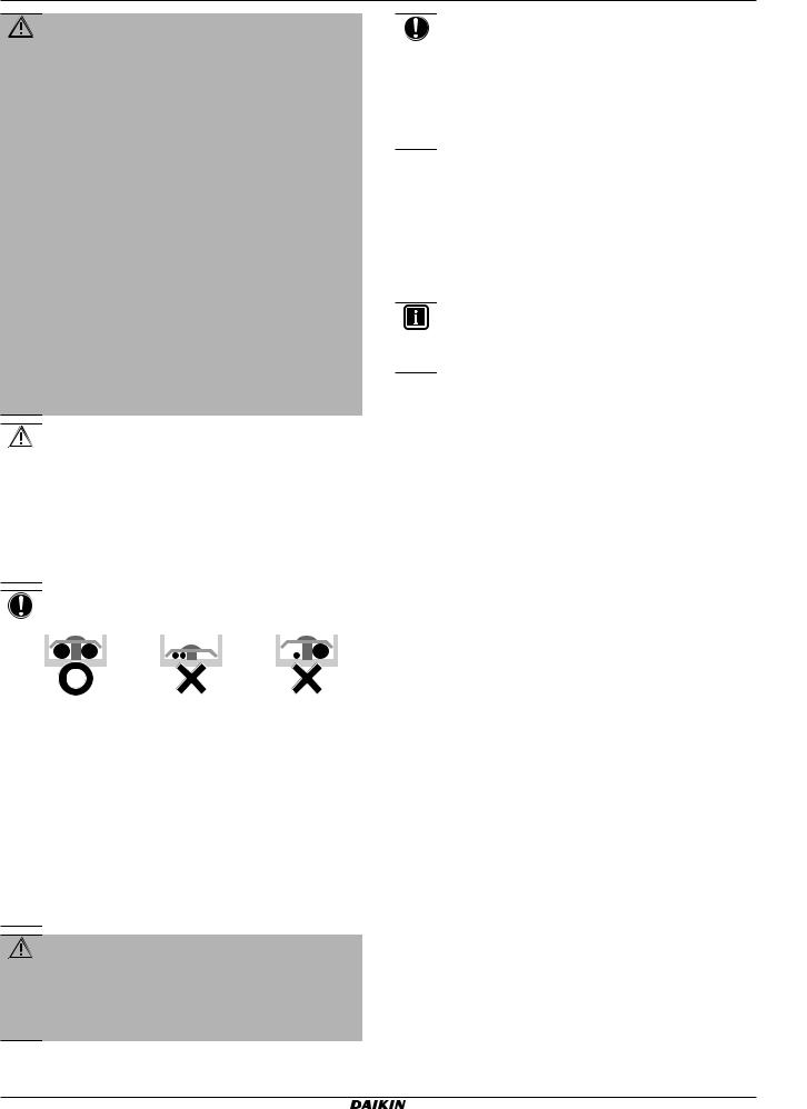
▪Do NOT place any objects or equipment on top of the unit.
▪Do NOT sit, climb or stand on the unit.
▪Units are marked with the following symbol:
1.1.1Meaning of warnings and symbols
DANGER
Indicates a situation that results in death or serious injury.
DANGER: RISK OF ELECTROCUTION
Indicates a situation that could result in electrocution.
DANGER: RISK OF BURNING
Indicates a situation that could result in burning because of extreme hot or cold temperatures.
DANGER: RISK OF EXPLOSION
Indicates a situation that could result in explosion.
WARNING
Indicates a situation that could result in death or serious injury.
WARNING: FLAMMABLE MATERIAL
CAUTION
Indicates a situation that could result in minor or moderate injury.
NOTICE
Indicates a situation that could result in equipment or property damage.
INFORMATION
Indicates useful tips or additional information.
Symbol |
Explanation |
Before installation, read the installation and operation manual, and the wiring instruction sheet.
Before performing maintenance and service tasks, read the service manual.
For more information, see the installer and user reference guide.
This means that electrical and electronic products may NOT be mixed with unsorted household waste. Do NOT try to dismantle the system yourself: the dismantling of the system, treatment of the refrigerant, of oil and of other parts must be done by an authorized installer and must comply with applicable legislation.
Units must be treated at a specialized treatment facility for reuse, recycling and recovery. By ensuring this product is disposed of correctly, you will help to prevent potential negative consequences for the environment and human health. For more information, contact your installer or local authority.
▪ Batteries are marked with the following symbol:
This means that the batteries may NOT be mixed with unsorted household waste. If a chemical symbol is printed beneath the symbol, this chemical symbol means that the battery contains a heavy metal above a certain concentration.
Possible chemical symbols are: Pb: lead (>0.004%).
Waste batteries must be treated at a specialized treatment facility for reuse. By ensuring waste batteries are disposed of correctly, you will help to prevent potential negative consequences for the environment and human health.
1.3For the installer
1.3.1General
If you are NOT sure how to install or operate the unit, contact your dealer.
NOTICE
Improper installation or attachment of equipment or accessories could result in electric shock, short-circuit, leaks, fire or other damage to the equipment. Only use accessories, optional equipment and spare parts made or approved by Daikin.
FFA25~60A2VEB(9) |
Installer and user reference guide |
Split system air conditioners |
3 |
4P550955-4 – 2018.08 |
1 General safety precautions
WARNING
Make sure installation, testing and applied materials comply with applicable legislation (on top of the instructions described in the Daikin documentation).
CAUTION
Wear adequate personal protective equipment (protective gloves, safety glasses,…) when installing, maintaining or servicing the system.
WARNING
Tear apart and throw away plastic packaging bags so that nobody, especially children, can play with them. Possible risk: suffocation.
DANGER: RISK OF BURNING
▪Do NOT touch the refrigerant piping, water piping or internal parts during and immediately after operation. It could be too hot or too cold. Give it time to return to normal temperature. If you must touch it, wear protective gloves.
▪Do NOT touch any accidental leaking refrigerant.
WARNING
Provide adequate measures to prevent that the unit can be used as a shelter by small animals. Small animals that make contact with electrical parts can cause malfunctions, smoke or fire.
CAUTION
Do NOT touch the air inlet or aluminium fins of the unit.
NOTICE
▪Do NOT place any objects or equipment on top of the unit.
▪Do NOT sit, climb or stand on the unit.
NOTICE
Works executed on the outdoor unit are best done under dry weather conditions to avoid water ingress.
In accordance with the applicable legislation, it might be necessary to provide a logbook with the product containing at least: information on maintenance, repair work, results of tests, stand-by periods,…
Also, at least, following information MUST be provided at an accessible place at the product:
▪Instructions for shutting down the system in case of an emergency
▪Name and address of fire department, police and hospital
▪Name, address and day and night telephone numbers for obtaining service
In Europe, EN378 provides the necessary guidance for this logbook.
1.3.2Installation site
▪Provide sufficient space around the unit for servicing and air circulation.
▪Make sure the installation site withstands the unit's weight and vibration.
▪Make sure the area is well ventilated. Do NOT block any ventilation openings.
▪Make sure the unit is level.
Do NOT install the unit in the following places:
▪ In potentially explosive atmospheres.
▪In places where there is machinery that emits electromagnetic waves. Electromagnetic waves may disturb the control system, and cause malfunction of the equipment.
▪In places where there is a risk of fire due to the leakage of flammable gases (example: thinner or gasoline), carbon fibre, ignitable dust.
▪In places where corrosive gas (example: sulphurous acid gas) is produced. Corrosion of copper pipes or soldered parts may cause the refrigerant to leak.
Instructions for equipment using R32 refrigerant
If applicable.
WARNING
▪Do NOT pierce or burn.
▪Do NOT use means to accelerate the defrosting process or to clean the equipment, other than those recommended by the manufacturer.
▪Be aware that R32 refrigerant does NOT contain an odour.
WARNING
The appliance shall be stored so as to prevent mechanical damage and in a well-ventilated room without continuously operating ignition sources (example: open flames, an operating gas appliance or an operating electric heater) and have a room size as specified below.
NOTICE
▪Do NOT re-use joints which have been used already.
▪Joints made in installation between parts of refrigerant system shall be accessible for maintenance purposes.
WARNING
Make sure installation, servicing, maintenance and repair comply with instructions from Daikin and with applicable legislation (for example national gas regulation) and are executed only by authorised persons.
Installation space requirements
NOTICE
▪Pipework shall be protected from physical damage.
▪Installation of pipework shall be kept to a minimum.
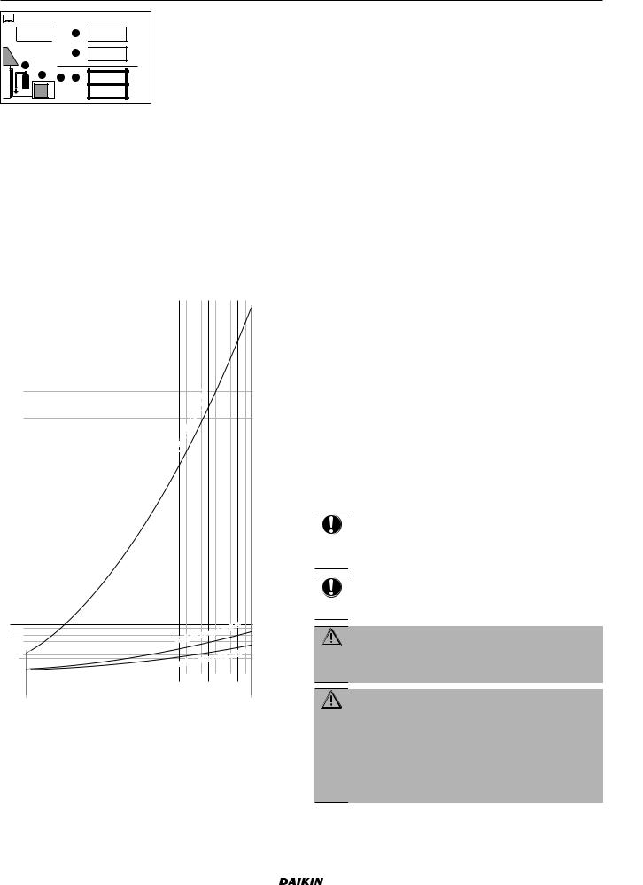
WARNING
If appliances contain R32 refrigerant, the floor area of the room in which the appliances are installed, operated and stored MUST be larger than the minimum floor area defined in table below A (m2). This applies to:
▪Indoor units without a refrigerant leakage sensor; in case of indoor units with refrigerant leakage sensor, consult the installation manual
▪Outdoor units installed or stored indoors (e.g. winter garden, garage, machinery room)
▪Pipework in unventilated spaces
To determine the minimum floor area
1Determine the total refrigerant charge in the system (= factory refrigerant charge  +
+  additional refrigerant amount
charged).
Installer and user reference guide |
FFA25~60A2VEB(9) |
4 |
Split system air conditioners |
4P550955-4 – 2018.08 |
Contains fluorinated greenhouse gases |
|
||
R32 |
1 |
= |
kg |
GWP: xxx |
2 |
= |
kg |
|
|||
2 |
|
|
|
1 |
1 + 2 = |
kg |
|
|
GWP × kg |
tCO2eq |
|
|
1000 |
= |
|
2Determine which graph or table to use.
▪For indoor units: Is the unit ceiling-mounted, wall-mounted or floor-standing?
▪For outdoor units installed or stored indoors, and field piping in unventilated spaces, this depends on the installation height:
If the installation height is… |
Then use the graph or table for… |
<1.8 m |
Floor-standing units |
|
|
1.8≤x<2.2 m |
Wall-mounted units |
≥2.2 m |
Ceiling-mounted units |
|
|
3 Use the graph or table to determine the minimum floor area.
Amin (m2)
550 |
|
|
|
|
|
|
|
|
|
|
|
|
|
|
|
|
|
|
|
|
|
|
|
|
|
|
|
|
|
|
|
|
|
|
|
540 |
|
|
|
|
|
|
|
|
|
|
|
|
|
|
|
|
|
|
|
|
|
|
|
|
|
|
|
|
|
|
|
|
|
|
|
530 |
|
|
|
|
|
|
|
|
|
|
|
|
|
|
|
|
|
|
|
|
|
|
|
|
|
|
|
|
|
|
|
|
|
|
|
|
|
|
|
|
|
|
|
|
|
|
|
|
|
|
|
|
|
|
|
|
|
|
|
|
|
|
|
|
|
|
|
|
|
|
|
520 |
|
|
|
|
|
|
|
|
|
|
|
|
|
|
|
|
|
|
|
|
|
|
|
|
|
|
|
|
|
|
|
|
|
|
|
|
|
|
|
|
|
|
|
|
|
|
|
|
|
|
|
|
|
|
|
|
|
|
|
|
|
|
|
|
|
|
|
|
|
||
510 |
|
|
|
|
|
|
|
|
|
|
|
|
|
|
|
|
|
|
|
|
|
|
|
|
|
|
|
|
|
|
|
|
|
|
|
|
|
|
|
|
|
|
|
|
|
|
|
|
|
|
|
|
|
|
|
|
|
|
|
|
|
|
|
|
|
|
|
|
|
|
|
500 |
|
|
|
|
|
|
|
|
|
|
|
|
|
|
|
|
|
|
|
|
|
|
|
|
|
|
|
|
|
|
|
|
|
|
|
|
|
|
|
|
|
|
|
|
|
|
|
|
|
|
|
|
|
|
|
|
|
|
|
|
|
|
|
|
|
|
|
|
|
||
490 |
|
|
|
|
|
|
|
|
|
|
|
|
|
|
|
|
|
|
|
|
|
|
|
|
|
|
|
|
|
|
|
|
|
|
|
|
|
|
|
|
|
|
|
|
|
|
|
|
|
|
|
|
|
|
|
|
|
|
|
|
|
|
|
|
|
|
|
|
|
|
|
480 |
|
|
|
|
|
|
|
|
|
|
|
|
|
|
|
|
|
|
|
|
|
|
|
|
|
|
|
|
|
|
|
|
|
|
|
|
|
|
|
|
|
|
|
|
|
|
|
|
|
|
|
|
|
|
|
|
|
|
|
|
|
|
|
|
|
|
|
|
|
||
470 |
|
|
|
|
|
|
|
|
|
|
|
|
|
|
|
|
|
|
|
|
|
|
|
|
|
|
|
|
|
|
|
|
|
|
|
|
|
|
|
|
|
|
|
|
|
|
|
|
|
|
|
|
|
|
|
|
|
|
|
|
|
|
|
|
|
|
|
|
|
|
|
460 |
|
|
|
|
|
|
|
|
|
|
|
|
|
|
|
|
|
|
|
|
|
|
|
|
|
|
|
|
|
|
|
|
|
|
|
|
|
|
|
|
|
|
|
|
|
|
|
|
|
|
|
|
|
|
|
|
|
|
|
|
|
|
|
|
|
|
|
|
|
||
450 |
|
|
|
|
|
|
|
|
|
|
|
|
|
|
|
|
|
|
|
|
|
|
|
|
|
|
|
|
|
|
|
|
|
|
|
|
|
|
|
|
|
|
|
|
|
|
|
|
|
|
|
|
|
|
|
|
|
|
|
|
|
|
|
|
|
|
|
|
|
|
|
440 |
|
|
|
|
|
|
|
|
|
|
|
|
|
|
|
|
|
|
|
|
|
|
|
|
|
|
|
|
|
|
|
|
|
|
|
|
|
|
|
|
|
|
|
|
|
|
|
|
|
|
|
|
|
|
|
|
|
|
|
|
|
|
|
|
|
|
|
|
|
||
430 |
|
|
|
|
|
|
|
|
|
|
|
|
|
|
|
|
|
|
|
|
|
|
|
|
|
|
|
|
|
|
|
|
|
|
|
|
|
|
|
|
|
|
|
|
|
|
|
|
|
|
|
|
|
|
|
|
|
|
|
|
|
|
|
|
|
|
|
|
|
|
|
420 |
|
|
|
|
|
|
|
|
|
|
|
|
|
|
|
|
|
|
|
|
|
|
|
|
|
|
|
|
|
|
|
|
|
|
|
|
|
|
|
|
|
|
|
|
|
|
|
|
|
|
|
|
|
|
|
|
|
|
|
|
|
|
|
|
|
|
|
|
|
||
410 |
|
|
|
|
|
|
|
|
|
|
|
|
|
|
|
|
|
|
|
|
|
|
|
|
|
|
|
(c) |
|
|
|
|
|
|
|
|
|
|
|
|
|
|
|
|
|
|
|
|
|
|
|
|
|
|
|
|
|
|
|
|
|
|
|
|
|
|
|
|
|
||
400 |
|
|
|
|
|
|
|
|
|
|
|
|
|
|
|
|
|
|
|
|
|
|
|
|
|
|
|
|
|
|
|
|
|
|
|
|
|
|
|
|
|
|
|
|
|
|
|
|
|
|
|
|
|
|
|
|
|
|
|
|
|
|
|
|
|
|
|
|
|
||
390 |
|
|
|
|
|
|
|
|
|
|
|
|
|
|
|
|
|
|
|
|
|
|
|
|
|
|
unit |
|
|
|
|
|
|
|
|
|
|
|
|
|
|
|
|
|
|
|
|
|
|
|
|
|
|
|
|
|
|
|
|
|
|
|
|
|
|
|
|
|
|
||
|
|
|
|
|
|
|
|
|
|
|
|
|
|
|
|
|
|
|
|
|
|
|
|
|
|
|
|
|
|
|
|
|
|
|
|
380 |
|
|
|
|
|
|
|
|
|
|
|
|
|
|
|
|
|
|
|
|
|
|
|
|
|
|
|
|
|
|
|
|
|
|
|
|
|
|
|
|
|
|
|
|
|
|
|
|
|
|
|
|
|
|
|
|
|
|
|
|
|
|
|
|
|
|
|
|
|
||
|
|
|
|
|
|
|
|
|
|
|
|
|
|
|
|
|
|
|
|
|
|
|
|
|
|
standing |
|
|
|
|
|
|
|
|
|
350360 |
|
|
|
|
|
|
|
|
|
|
|
|
|
|
|
|
|
|
|
|
|
|
|
|
- |
|
|
|
|
|
|
|
|
||
370 |
|
|
|
|
|
|
|
|
|
|
|
|
|
|
|
|
|
|
|
|
|
|
|
|
|
|
|
|
|
|
|
|
|
|
|
|
|
|
|
|
|
|
|
|
|
|
|
|
|
|
|
|
|
|
|
|
|
|
|
|
|
|
|
|
|
|
|
|
|
|
|
|
|
|
|
|
|
|
|
|
|
|
|
|
|
|
|
|
|
|
|
|
|
|
|
|
|
|
|
|
|
|
|
|
|
|
|
|
|
|
|
|
|
|
|
|
|
|
|
|
|
|
|
|
|
|
|
|
|
|
|
|
|
|
|
|
|
|
|
|
|
|
|
330 |
340 |
|
|
|
|
|
|
|
|
|
|
|
|
|
|
|
|
|
|
|
|
|
|
|
Floor |
|
|
|
|
|
|
|
|
|
|
|
|
|
|
|
|
|
|
|
|
|
|
|
|
|
|
|
|
|
|
|
|
|
|
|
|
|
|
|
|
|
|
|
|
||
|
|
|
|
|
|
|
|
|
|
|
|
|
|
|
|
|
|
|
|
|
|
|
|
|
|
|
|
|
|
|
|
|
|
||
|
|
|
|
|
|
|
|
|
|
|
|
|
|
|
|
|
|
|
|
|
|
|
|
|
|
|
|
|
|
|
|
|
|
|
|
320 |
|
|
|
|
|
|
|
|
|
|
|
|
|
|
|
|
|
|
|
|
|
|
|
|
|
|
|
|
|
|
|
|
|
|
|
310 |
|
|
|
|
|
|
|
|
|
|
|
|
|
|
|
|
|
|
|
|
|
|
|
|
|
|
|
|
|
|
|
|
|
|
|
|
|
|
|
|
|
|
|
|
|
|
|
|
|
|
|
|
|
|
|
|
|
|
|
|
|
|
|
|
|
|
|
|
|
||
|
|
|
|
|
|
|
|
|
|
|
|
|
|
|
|
|
|
|
|
|
|
|
|
|
|
|
|
|
|
|
|
|
|
|
|
300 |
|
|
|
|
|
|
|
|
|
|
|
|
|
|
|
|
|
|
|
|
|
|
|
|
|
|
|
|
|
|
|
|
|
|
|
|
|
|
|
|
|
|
|
|
|
|
|
|
|
|
|
|
|
|
|
|
|
|
|
|
|
|
|
|
|
|
|
|
|
||
290 |
|
|
|
|
|
|
|
|
|
|
|
|
|
|
|
|
|
|
|
|
|
|
|
|
|
|
|
|
|
|
|
|
|
|
|
|
|
|
|
|
|
|
|
|
|
|
|
|
|
|
|
|
|
|
|
|
|
|
|
|
|
|
|
|
|
|
|
|
|
|
|
280 |
|
|
|
|
|
|
|
|
|
|
|
|
|
|
|
|
|
|
|
|
|
|
|
|
|
|
|
|
|
|
|
|
|
|
|
|
|
|
|
|
|
|
|
|
|
|
|
|
|
|
|
|
|
|
|
|
|
|
|
|
|
|
|
|
|
|
|
|
|
||
270 |
|
|
|
|
|
|
|
|
|
|
|
|
|
|
|
|
|
|
|
|
|
|
|
|
|
|
|
|
|
|
|
|
|
|
|
|
|
|
|
|
|
|
|
|
|
|
|
|
|
|
|
|
|
|
|
|
|
|
|
|
|
|
|
|
|
|
|
|
|
|
|
260 |
|
|
|
|
|
|
|
|
|
|
|
|
|
|
|
|
|
|
|
|
|
|
|
|
|
|
|
|
|
|
|
|
|
|
|
|
|
|
|
|
|
|
|
|
|
|
|
|
|
|
|
|
|
|
|
|
|
|
|
|
|
|
|
|
|
|
|
|
|
||
250 |
|
|
|
|
|
|
|
|
|
|
|
|
|
|
|
|
|
|
|
|
|
|
|
|
|
|
|
|
|
|
|
|
|
|
|
|
|
|
|
|
|
|
|
|
|
|
|
|
|
|
|
|
|
|
|
|
|
|
|
|
|
|
|
|
|
|
|
|
|
|
|
240 |
|
|
|
|
|
|
|
|
|
|
|
|
|
|
|
|
|
|
|
|
|
|
|
|
|
|
|
|
|
|
|
|
|
|
|
|
|
|
|
|
|
|
|
|
|
|
|
|
|
|
|
|
|
|
|
|
|
|
|
|
|
|
|
|
|
|
|
|
|
||
230 |
|
|
|
|
|
|
|
|
|
|
|
|
|
|
|
|
|
|
|
|
|
|
|
|
|
|
|
|
|
|
|
|
|
|
|
|
|
|
|
|
|
|
|
|
|
|
|
|
|
|
|
|
|
|
|
|
|
|
|
|
|
|
|
|
|
|
|
|
|
|
|
220 |
|
|
|
|
|
|
|
|
|
|
|
|
|
|
|
|
|
|
|
|
|
|
|
|
|
|
|
|
|
|
|
|
|
|
|
|
|
|
|
|
|
|
|
|
|
|
|
|
|
|
|
|
|
|
|
|
|
|
|
|
|
|
|
|
|
|
|
|
|
||
210 |
|
|
|
|
|
|
|
|
|
|
|
|
|
|
|
|
|
|
|
|
|
|
|
|
|
|
|
|
|
|
|
|
|
|
|
|
|
|
|
|
|
|
|
|
|
|
|
|
|
|
|
|
|
|
|
|
|
|
|
|
|
|
|
|
|
|
|
|
|
|
|
200 |
|
|
|
|
|
|
|
|
|
|
|
|
|
|
|
|
|
|
|
|
|
|
|
|
|
|
|
|
|
|
|
|
|
|
|
|
|
|
|
|
|
|
|
|
|
|
|
|
|
|
|
|
|
|
|
|
|
|
|
|
|
|
|
|
|
|
|
|
|
||
190 |
|
|
|
|
|
|
|
|
|
|
|
|
|
|
|
|
|
|
|
|
|
|
|
|
|
|
|
|
|
|
|
|
|
|
|
|
|
|
|
|
|
|
|
|
|
|
|
|
|
|
|
|
|
|
|
|
|
|
|
|
|
|
|
|
|
|
|
|
|
|
|
180 |
|
|
|
|
|
|
|
|
|
|
|
|
|
|
|
|
|
|
|
|
|
|
|
|
|
|
|
|
|
|
|
|
|
|
|
|
|
|
|
|
|
|
|
|
|
|
|
|
|
|
|
|
|
|
|
|
|
|
|
|
|
|
|
|
|
|
|
|
|
||
170 |
|
|
|
|
|
|
|
|
|
|
|
|
|
|
|
|
|
|
|
|
|
|
|
|
|
|
|
|
|
|
|
|
|
|
|
|
|
|
|
|
|
|
|
|
|
|
|
|
|
|
|
|
|
|
|
|
|
|
|
|
|
|
|
|
|
|
|
|
|
|
|
160 |
|
|
|
|
|
|
|
|
|
|
|
|
|
|
|
|
|
|
|
|
|
|
|
|
|
|
|
|
|
|
|
|
|
|
|
|
|
|
|
|
|
|
|
|
|
|
|
|
|
|
|
|
|
|
|
|
|
|
|
|
|
|
|
|
|
|
|
|
|
||
150 |
|
|
|
|
|
|
|
|
|
|
|
|
|
|
|
|
|
|
|
|
|
|
|
|
|
|
|
|
|
|
|
|
|
|
|
|
|
|
|
|
|
|
|
|
|
|
|
|
|
|
|
|
|
|
|
|
|
|
|
|
|
|
|
|
|
|
|
|
|
|
|
140 |
|
|
|
|
|
|
|
|
|
|
|
|
|
|
|
|
|
|
|
|
|
|
|
|
|
|
|
|
|
|
|
|
|
|
|
|
|
|
|
|
|
|
|
|
|
|
|
|
|
|
|
|
|
|
|
|
|
|
|
|
|
|
|
|
|
|
|
|
|
||
130 |
|
|
|
|
|
|
|
|
|
|
|
|
|
|
|
|
|
|
|
|
|
|
|
|
|
|
|
|
|
|
|
|
|
|
|
|
|
|
|
|
|
|
|
|
|
|
|
|
|
|
|
|
|
|
|
|
|
|
|
|
|
|
|
|
|
|
|
|
|
|
|
120 |
|
|
|
|
|
|
|
|
|
|
|
|
|
|
|
|
|
|
|
|
|
|
|
|
|
|
|
|
|
|
|
|
|
|
|
|
|
|
|
|
|
|
|
|
|
|
|
|
|
|
|
|
|
|
|
|
|
|
|
|
|
|
|
|
|
|
|
|
|
||
110 |
|
|
|
|
|
|
|
|
|
|
|
|
|
|
|
|
|
|
|
|
|
|
|
|
|
|
|
|
|
|
|
|
|
|
|
|
|
|
|
|
|
|
|
|
|
|
|
|
|
|
|
|
|
|
|
|
|
|
|
|
|
|
|
|
|
|
|
|
|
|
|
100 |
|
|
|
|
|
|
|
|
|
|
|
|
|
|
|
|
|
|
|
|
|
|
|
|
|
|
|
|
|
|
|
|
|
|
|
90 |
|
|
|
|
|
|
|
|
|
|
|
|
|
|
|
|
|
|
|
|
|
|
|
|
|
|
|
|
|
|
|
|
|
|
|
|
|
|
|
|
|
|
|
|
|
|
|
|
|
|
|
|
|
|
|
|
|
|
|
|
|
|
|
|
|
|
|
|
|
||
|
|
|
|
|
|
|
|
|
|
|
|
|
|
|
|
|
|
|
|
|
|
|
|
|
|
|
|
|
|
|
|
|
|
|
|
80 |
|
|
|
|
|
|
|
|
|
|
|
|
|
|
|
|
|
|
|
|
|
|
|
|
|
|
|
|
|
|
|
|
|
|
|
|
|
|
|
|
|
|
|
|
|
|
|
|
|
|
|
|
|
|
|
|
|
|
|
|
|
|
|
|
|
|
|
|
|
||
70 |
|
|
|
|
|
|
|
|
|
|
|
|
|
|
|
|
|
|
|
|
|
|
|
|
|
|
|
|
|
|
|
|
|
|
|
|
60 |
|
|
|
|
|
|
|
|
|
|
|
|
|
|
|
|
|
|
|
|
|
|
|
|
|
|
|
|
|
unit |
(b) |
|
|
|
|
|
|
|
|
|
|
|
|
|
|
|
|
|
|
|
|
|
|
|
|
|
|
|
|
|
|
|
|
|
|
|
|
|||
50 |
|
|
|
|
|
|
|
|
|
|
|
|
|
|
|
|
|
|
|
|
|
|
|
Wall |
- |
mounted |
|
|
|
|
|
||||
40 |
|
|
|
|
|
|
|
|
|
|
|
|
|
|
|
|
|
|
|
|
|
|
|
|
|
|
|
||||||||
|
|
|
|
|
|
|
|
|
|
|
|
|
|
|
|
|
|
|
|
|
|
|
|
|
|
|
|
|
|
|
|
||||
30 |
|
|
|
|
|
|
|
|
|
|
|
|
|
|
|
|
|
|
|
|
|
|
|
|
|
|
|
|
|
|
|
|
|||
|
|
|
|
|
|
|
|
|
|
|
|
|
|
|
|
|
|
|
|
|
|
|
|
|
|
|
|
|
|
|
|
|
|
||
|
|
|
|
|
|
|
|
|
|
|
|
|
|
|
|
|
|
|
|
|
|
|
|
|
|
|
|
|
|
|
|
|
(a) |
|
|
|
|
|
|
|
|
|
|
|
|
|
|
|
|
|
|
|
|
|
|
|
|
|
|
|
|
|
|
|
|
|
|
|
|
|
|
|
20 |
|
|
|
|
|
|
|
|
|
|
|
|
|
|
|
|
|
|
|
|
|
|
|
|
|
|
-mounted |
|
|
unit |
|
|
||
|
|
|
|
|
|
|
|
|
|
|
|
|
|
|
|
|
|
|
|
|
|
|
|
|
|
|
|
|
|
|
|
||||
10 |
|
|
|
|
|
|
|
|
|
|
|
|
|
|
|
|
|
|
|
|
|
Ceiling |
|
|
|
|
|
|
|
|
|||||
|
|
|
|
|
|
|
|
|
|
|
|
|
|
|
|
|
|
|
|
|
|
|
|
|
|
|
|
|
|
|
|
||||
0 |
|
|
|
|
|
|
|
|
|
|
|
|
|
|
|
|
|
|
|
|
|
|
|
|
|
|
|
|
|
|
|
|
|
||
|
|
|
|
|
|
|
|
|
|
|
|
|
|
|
|
|
|
|
|
|
|
|
|
|
|
|
|
|
|
|
|
|
|||
|
1.8 |
2.2 |
2.6 |
3 |
3.4 |
3.8 |
4.2 |
4.6 |
5 |
5.4 |
5.8 6.2 |
6.6 7 |
7.4 7.8 |
|
|||||||||||||||||||||
|
2 2.4 2.8 3.2 3.6 4 |
|
4.4 4.8 5.2 5.6 6 6.4 6.8 7.2 7.6 8.0 m (kg) |
||||||||||||||||||||||||||||||||
|
1.843 |
|
|
|
|
|
|
|
|
|
|
|
|
|
|
|
|
|
|
|
|
|
|
|
|
|
7.956 |
|
|||||||
1 General safety precautions
Ceiling-mounted |
|
Wall-mounted |
|
Floor-standing |
||||||||||||
|
|
unit(a) |
|
|
unit(b) |
|
|
|
unit(c) |
|||||||
m (kg) |
|
|
Amin (m2) |
|
m (kg) |
|
|
|
Amin (m2) |
|
m (kg) |
|
|
Amin (m2) |
||
|
|
|
|
|
|
|
|
|
||||||||
≤1.842 |
|
|
— |
|
≤1.842 |
|
|
|
— |
|
≤1.842 |
|
|
— |
||
1.843 |
|
|
|
3.64 |
|
1.843 |
|
|
|
4.45 |
|
1.843 |
|
|
|
28.9 |
2.0 |
|
|
|
3.95 |
|
2.0 |
|
|
|
4.83 |
|
2.0 |
|
|
|
34.0 |
2.2 |
|
|
|
4.34 |
|
2.2 |
|
|
|
5.31 |
|
2.2 |
|
|
|
41.2 |
2.4 |
|
|
|
4.74 |
|
2.4 |
|
|
|
5.79 |
|
2.4 |
|
|
|
49.0 |
2.6 |
|
|
|
5.13 |
|
2.6 |
|
|
|
6.39 |
|
2.6 |
|
|
|
57.5 |
2.8 |
|
|
|
5.53 |
|
2.8 |
|
|
|
7.41 |
|
2.8 |
|
|
|
66.7 |
3.0 |
|
|
|
5.92 |
|
3.0 |
|
|
|
8.51 |
|
3.0 |
|
|
|
76.6 |
3.2 |
|
|
|
6.48 |
|
3.2 |
|
|
|
9.68 |
|
3.2 |
|
|
|
87.2 |
3.4 |
|
|
|
7.32 |
|
3.4 |
|
|
|
10.9 |
|
3.4 |
|
|
|
98.4 |
3.6 |
|
|
|
8.20 |
|
3.6 |
|
|
|
12.3 |
|
3.6 |
|
|
|
110 |
3.8 |
|
|
|
9.14 |
|
3.8 |
|
|
|
13.7 |
|
3.8 |
|
|
|
123 |
4.0 |
|
|
|
10.1 |
|
4.0 |
|
|
|
15.1 |
|
4.0 |
|
|
|
136 |
4.2 |
|
|
|
11.2 |
|
4.2 |
|
|
|
16.7 |
|
4.2 |
|
|
|
150 |
4.4 |
|
|
|
12.3 |
|
4.4 |
|
|
|
18.3 |
|
4.4 |
|
|
|
165 |
4.6 |
|
|
13.4 |
|
4.6 |
|
20.0 |
|
4.6 |
|
|
180 |
||||
|
|
|
|
|
|
|
|
|||||||||
4.8 |
|
|
14.6 |
|
4.8 |
|
21.8 |
|
4.8 |
|
|
196 |
||||
|
|
|
|
|
|
|
|
|||||||||
5.0 |
|
|
15.8 |
|
5.0 |
|
23.6 |
|
5.0 |
|
|
213 |
||||
|
|
|
|
|
|
|
|
|||||||||
5.2 |
|
|
17.1 |
|
5.2 |
|
25.6 |
|
5.2 |
|
|
230 |
||||
|
|
|
|
|
|
|
|
|||||||||
5.4 |
|
|
18.5 |
|
5.4 |
|
27.6 |
|
5.4 |
|
|
248 |
||||
|
|
|
|
|
|
|
|
|||||||||
5.6 |
|
|
19.9 |
|
5.6 |
|
29.7 |
|
5.6 |
|
|
267 |
||||
|
|
|
|
|
|
|
|
|||||||||
5.8 |
|
|
21.3 |
|
5.8 |
|
31.8 |
|
5.8 |
|
|
286 |
||||
|
|
|
|
|
|
|
|
|||||||||
6.0 |
|
|
22.8 |
|
6.0 |
|
34.0 |
|
6.0 |
|
|
306 |
||||
|
|
|
|
|
|
|
|
|||||||||
6.2 |
|
|
24.3 |
|
6.2 |
|
36.4 |
|
6.2 |
|
|
327 |
||||
|
|
|
|
|
|
|
|
|||||||||
6.4 |
|
|
25.9 |
|
6.4 |
|
38.7 |
|
6.4 |
|
|
349 |
||||
|
|
|
|
|
|
|
|
|||||||||
6.6 |
|
|
27.6 |
|
6.6 |
|
41.2 |
|
6.6 |
|
|
371 |
||||
|
|
|
|
|
|
|
|
|||||||||
6.8 |
|
|
29.3 |
|
6.8 |
|
43.7 |
|
6.8 |
|
|
394 |
||||
|
|
|
|
|
|
|
|
|||||||||
7.0 |
|
|
31.0 |
|
7.0 |
|
46.3 |
|
7.0 |
|
|
417 |
||||
|
|
|
|
|
|
|
|
|||||||||
7.2 |
|
|
32.8 |
|
7.2 |
|
49.0 |
|
7.2 |
|
|
441 |
||||
|
|
|
|
|
|
|
|
|||||||||
7.4 |
|
|
34.7 |
|
7.4 |
|
51.8 |
|
7.4 |
|
|
466 |
||||
|
|
|
|
|
|
|
|
|||||||||
7.6 |
|
|
36.6 |
|
7.6 |
|
54.6 |
|
7.6 |
|
|
492 |
||||
|
|
|
|
|
|
|
|
|||||||||
7.8 |
|
|
38.5 |
|
7.8 |
|
57.5 |
|
7.8 |
|
|
518 |
||||
|
|
|
|
|
|
|
|
|||||||||
7.956 |
|
|
40.1 |
|
7.956 |
|
59.9 |
|
7.956 |
|
|
539 |
||||
|
|
|
|
|
|
|
|
|||||||||
|
|
|
|
|
|
|
|
|
|
|
|
|
|
|
|
|
m |
Total refrigerant charge in the system |
Amin |
Minimum floor area |
(a)Ceiling-mounted unit (= Ceiling-mounted unit)
(b)Wall-mounted unit (= Wall-mounted unit)
(c)Floor-standing unit (= Floor-standing unit)
1.3.3Refrigerant
If applicable. See the installation manual or installer reference guide of your application for more information.
NOTICE
Make sure refrigerant piping installation complies with applicable legislation. In Europe, EN378 is the applicable standard.
NOTICE
Make sure the field piping and connections are NOT subjected to stress.
WARNING
During tests, NEVER pressurize the product with a pressure higher than the maximum allowable pressure (as indicated on the nameplate of the unit).
WARNING
Take sufficient precautions in case of refrigerant leakage. If refrigerant gas leaks, ventilate the area immediately. Possible risks:
▪Excessive refrigerant concentrations in a closed room can lead to oxygen deficiency.
▪Toxic gas may be produced if refrigerant gas comes into contact with fire.
|
|
|
|
|
|
|
|
FFA25~60A2VEB(9) |
Installer and user reference guide |
|
|
Split system air conditioners |
5 |
|
|
4P550955-4 – 2018.08 |
|
||
1 General safety precautions
DANGER: RISK OF EXPLOSION
Pump down – Refrigerant leakage. If you want to pump down the system, and there is a leak in the refrigerant circuit:
▪Do NOT use the unit's automatic pump down function, with which you can collect all refrigerant from the system into the outdoor unit. Possible consequence:
Self-combustion and explosion of the compressor because of air going into the operating compressor.
▪Use a separate recovery system so that the unit's compressor does NOT have to operate.
WARNING
ALWAYS recover the refrigerant. Do NOT release them directly into the environment. Use a vacuum pump to evacuate the installation.
NOTICE
After all the piping has been connected, make sure there is no gas leak. Use nitrogen to perform a gas leak detection.
NOTICE
▪To avoid compressor breakdown, do NOT charge more than the specified amount of refrigerant.
▪When the refrigerant system is to be opened, refrigerant MUST be treated according to the applicable legislation.
WARNING
Make sure there is no oxygen in the system. Refrigerant may only be charged after performing the leak test and the vacuum drying.
▪In case re-charge is required, refer to the nameplate of the unit. It states the type of refrigerant and necessary amount.
▪The unit is factory charged with refrigerant and depending on pipe sizes and pipe lengths some systems require additional charging of refrigerant.
▪Only use tools exclusively for the refrigerant type used in the system, this to ensure pressure resistance and prevent foreign materials from entering into the system.
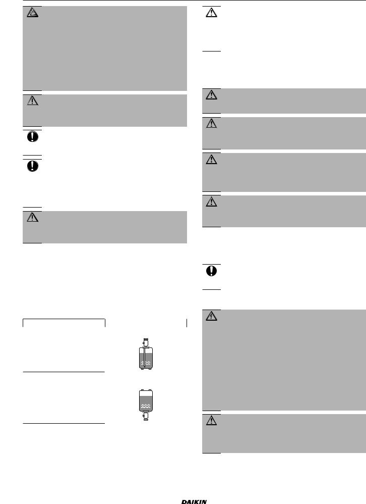
▪Charge the liquid refrigerant as follows:
If |
Then |
A siphon tube is present |
Charge with the cylinder upright. |
(i.e., the cylinder is marked with "Liquid filling siphon attached")
A siphon tube is NOT present |
Charge with the cylinder upside |
|
down. |
▪Open refrigerant cylinders slowly.
▪Charge the refrigerant in liquid form. Adding it in gas form may prevent normal operation.
CAUTION
When the refrigerant charging procedure is done or when pausing, close the valve of the refrigerant tank immediately. If the valve is NOT closed immediately, remaining pressure might charge additional refrigerant.
Possible consequence: Incorrect refrigerant amount.
1.3.4Brine
If applicable. See the installation manual or installer reference guide of your application for more information.
WARNING
The selection of the brine MUST be in accordance with the applicable legislation.
WARNING
Take sufficient precautions in case of brine leakage. If brine leaks, ventilate the area immediately and contact your local dealer.
WARNING
The ambient temperature inside the unit can get much higher than that of the room, e.g. 70°C. In case of a brine leak, hot parts inside the unit can create a hazardous situation.
WARNING
The use and installation of the application MUST comply with the safety and environmental precautions specified in the applicable legislation.
1.3.5Water
If applicable. See the installation manual or installer reference guide of your application for more information.
NOTICE
Make sure water quality complies with EU directive 98/83 EC.
1.3.6Electrical
DANGER: RISK OF ELECTROCUTION
▪Turn OFF all power supply before removing the switch box cover, connecting electrical wiring or touching electrical parts.
▪Disconnect the power supply for more than 1 minute, and measure the voltage at the terminals of main circuit capacitors or electrical components before servicing. The voltage MUST be less than 50 V DC before you can touch electrical components. For the location of the terminals, see the wiring diagram.
▪Do NOT touch electrical components with wet hands.
▪Do NOT leave the unit unattended when the service cover is removed.
WARNING
If NOT factory installed, a main switch or other means for disconnection, having a contact separation in all poles providing full disconnection under overvoltage category III condition, MUST be installed in the fixed wiring.
|
|
|
|
|
|
|
|
|
|
Installer and user reference guide |
FFA25~60A2VEB(9) |
6 |
Split system air conditioners |
||
4P550955-4 – 2018.08 |
|||
2 About the documentation
WARNING
▪ONLY use copper wires.
▪Make sure the field wiring complies with the applicable legislation.
▪All field wiring MUST be performed in accordance with the wiring diagram supplied with the product.
▪NEVER squeeze bundled cables and make sure they do NOT come in contact with the piping and sharp edges. Make sure no external pressure is applied to the terminal connections.
▪Make sure to install earth wiring. Do NOT earth the unit to a utility pipe, surge absorber, or telephone earth. Incomplete earth may cause electrical shock.
▪Make sure to use a dedicated power circuit. NEVER use a power supply shared by another appliance.
▪Make sure to install the required fuses or circuit breakers.
▪Make sure to install an earth leakage protector. Failure to do so may cause electric shock or fire.
▪When installing the earth leakage protector, make sure it is compatible with the inverter (resistant to high frequency electric noise) to avoid unnecessary opening of the earth leakage protector.
CAUTION
When connecting the power supply, the earth connection must be made before the current-carrying connections are established. When disconnecting the power supply, the current-carrying connections must be separated before the earth connection is. The length of the conductors between the power supply stress relief and the terminal block itself must be as such that the current-carrying wires are tautened before the earth wire is in case the power supply is pulled loose from the stress relief.
NOTICE
Precautions when laying power wiring:
▪Do NOT connect wiring of different thicknesses to the power terminal block (slack in the power wiring may cause abnormal heat).
▪When connecting wiring which is the same thickness, do as shown in the figure above.
▪For wiring, use the designated power wire and connect firmly, then secure to prevent outside pressure being exerted on the terminal board.
▪Use an appropriate screwdriver for tightening the terminal screws. A screwdriver with a small head will damage the head and make proper tightening impossible.
▪Over-tightening the terminal screws may break them.
WARNING
▪After finishing the electrical work, confirm that each electrical component and terminal inside the electrical components box is connected securely.
▪Make sure all covers are closed before starting up the unit.
NOTICE
Only applicable if the power supply is three phase, and the compressor has an ON/OFF starting method.
If there exists the possibility of reversed phase after a momentary black out and the power goes on and off while the product is operating, attach a reversed phase protection circuit locally. Running the product in reversed phase can break the compressor and other parts.
2 About the documentation
2.1About this document
Target audience
Authorised installers + end users
INFORMATION
This appliance is intended to be used by expert or trained users in shops, in light industry, and on farms, or for commercial and household use by lay persons.
Documentation set
This document is part of a documentation set. The complete set consists of:
▪General safety precautions:
▪Safety instructions that you must read before installing
▪Format: Paper (in the box of the indoor unit)
▪Indoor unit installation and operation manual:
▪Installation and operation instructions
▪Format: Paper (in the box of the indoor unit)
▪Installer and user reference guide:
▪Preparation of the installation, good practices, reference data,…
▪Detailed step-by-step instructions and background information for basic and advanced usage
▪Format: Digital files on http://www.daikineurope.com/support- and-manuals/product-information/
Latest revisions of the supplied documentation may be available on the regional Daikin website or via your dealer.
The original documentation is written in English. All other languages are translations.
Technical engineering data
▪A subset of the latest technical data is available on the regional
Daikin website (publicly accessible).
▪The full set of latest technical data is available on the Daikin extranet (authentication required).
2.2Installer and user reference guide at a glance
Chapter |
Description |
|
|
General safety |
Safety instructions that you must read |
|
|
precautions |
before installing |
|
|
About the documentation |
What documentation exists for the |
|
|
|
installer |
|
|
About the box |
How to unpack the units and remove |
|
|
|
their accessories |
|
|
|
|
|
|
|
|
|
|
FFA25~60A2VEB(9) |
Installer and user reference guide |
Split system air conditioners |
7 |
4P550955-4 – 2018.08 |
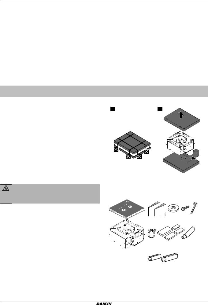
3 About the box
Chapter |
Description |
About the units and |
▪ How to identify the units |
options |
▪ System layout |
|
|
|
▪ Possible combinations of units and |
|
options |
Preparation |
What to do and know before going |
|
on site |
Installation |
What to do and know to install the |
|
system |
Configuration |
What to do and know to configure the |
|
system after it is installed |
Commissioning |
What to do and know to commission the |
|
system after it is configured |
Hand over to the user |
What to give and explain to the user |
For the installer
Chapter |
|
Description |
Disposal |
How to dispose of the system |
|
|
|
|
Technical data |
Specifications of the system |
|
About the system |
▪ |
System layout |
|
▪ |
User interface |
Before operation |
What to do before starting operation |
|
|
|
|
Operation |
How to operate the system |
|
Energy saving and |
How to save energy |
|
optimum operation |
|
|
Maintenance and service |
How to maintain and service the units |
|
Troubleshooting |
What to do in case of problems |
|
|
|
|
Relocation |
How to relocate the system |
|
Disposal |
How to dispose of the system |
|
Glossary |
Definition of terms |
|
|
|
|
3 About the box
3.1Overview: About the box
This chapter describes what you have to do after the box with the indoor unit is delivered on-site.
Keep the following in mind:
▪At delivery, the unit MUST be checked for damage. Any damage MUST be reported immediately to the carrier's claims agent.
▪Bring the packed unit as close as possible to its final installation position to prevent damage during transport.
▪Prepare the path along which you want to bring the unit inside in advance.
3.2Indoor unit
WARNING: FLAMMABLE MATERIAL
The R32 refrigerant (if applicable) in this unit is mildly flammable. Refer to the outdoor unit specifications for the type of refrigerant to be used.
3.2.1To unpack and handle the unit
Use a sling of soft material or protective plates together with a rope when lifting the unit. This to avoid damage or scratches to the unit.
Lift the unit by holding on to the hanger brackets without exerting any pressure on other parts, especially on refrigerant piping, drain piping and other resin parts.
1 |
|
2 |
|
|
|
3.2.2To remove the accessories from the indoor unit
a |
b |
c |
d |
e |
f |
|
1× |
1× |
8× |
4× |
7× |
g |
h |
i |
|
1× |
4× |
1× |
|
|
|
|
|
|
|
|
|
j k
1× 1×
aPaper pattern for installation (upper part of packing)
bGeneral safety precautions
cIndoor unit installation and operation manual
dWashers for hanger bracket
eScrews
fCable ties
gMetal clamp
hSealing pads: Large (drain pipe), medium 1 (gas pipe), medium 2 (liquid pipe), small (electrical wiring)
iDrain hose
Installer and user reference guide |
FFA25~60A2VEB(9) |
8 |
Split system air conditioners |
4P550955-4 – 2018.08 |

4 About the units and options
jInsulation piece: Small (liquid pipe)
kInsulation piece: Large (gas pipe)
4 About the units and options
4.1Overview: About the units and options
This chapter contains information about:
▪Identifying the indoor unit
▪Combining outdoor and indoor units
▪Combining the indoor unit with options
INFORMATION
For year round cooling applications with low indoor humidity conditions, such as Electronic Data Processing rooms, contact your dealer or see the engineering databook or the service manual.
4.2Identification
NOTICE
When installing or servicing several units at the same time, make sure NOT to switch the service panels between different models.
4.2.1Identification label: Indoor unit
Location
4.3About the indoor unit
Use the system in the following temperature and humidity ranges for safe and effective operation.
For combination with R410A outdoor unit, refer to the following table:
Outdoor units |
|
Cooling |
Heating |
RR71~125 |
|
–15~46°C DB |
— |
|
|
|
|
|
|
18~37°C DB |
— |
|
|
12~28°C WB |
|
RQ71~125 |
|
–5~46°C DB |
–9~21°C DB |
|
|
|
–10~15°C WB |
|
|
18~37°C DB |
10~27°C DB |
|
|
12~28°C WB |
|
|
|
|
|
RXS25~60 |
|
–10~46°C DB |
–15~24°C DB |
|
|
|
–16~18°C WB |
|
|
18~32°C DB |
10~30°C DB |
|
|
|
|
Outdoor units |
|
Cooling |
Heating |
2MXS50 |
|
10~46°C DB |
–15~24°C DB |
|
|
|
–16~18°C WB |
|
|
|
|
|
|
18~32°C DB |
10~30°C DB |
|
|
|
|
3MXS40~68 |
|
–10~46°C DB |
–15~24°C DB |
4MXS68~80 |
|
|
–16~18°C WB |
|
|
|
|
5MXS90 |
|
18~32°C DB |
10~30°C DB |
|
|
|
|
RZQG71~140 |
|
–15~50°C DB |
–19~21°C DB |
|
|
|
–20~15.5°C WB |
|
|
|
|
|
|
18~37°C DB |
10~27°C DB |
|
|
12~28°C WB |
|
RZQSG71~140 |
|
–15~46°C DB |
–14~21°C DB |
|
|
|
–15~15.5°C WB |
|
|
|
|
|
|
20~37°C DB |
10~27°C DB |
|
|
14~28°C WB |
|
|
|
|
|
RZQ200~250 |
|
–5~46°C DB |
–14~21°C DB |
|
|
|
–15~15°C WB |
|
|
20~37°C DB |
10~27°C DB |
|
|
14~28°C WB |
|
|
|
|
|
For combination with R32 outdoor unit, refer to the following table:
Outdoor units |
|
Cooling |
Heating |
RXM25~60 |
|
–10~46°C DB |
–15~24°C DB |
|
|
|
–16~18°C WB |
|
|
18~32°C DB |
10~30°C DB |
|
|
|
|
2MXM50 |
|
–10~46°C DB |
–15~24°C DB |
3MXM40~68 |
|
|
–16~18°C WB |
4MXM68~80 |
|
18~32°C DB |
10~30°C DB |
5MXM90 |
|
|
|
RZAG35~60 |
|
–20~52°C DB |
–20~24°C DB |
|
|
|
–21~18°C WB |
|
|
18~32°C DB |
10~30°C DB |
|
|
|
|
RZAG71~140 |
|
–20~52°C DB |
–19.5~21°C DB |
|
|
|
–20~15.5°C WB |
|
|
|
|
|
|
18~37°C DB |
10~27°C DB |
|
|
12~28°C WB |
|
|
|
|
|
RZASG71~140 |
|
–15~46°C DB |
–14~21°C DB |
|
|
|
–15~15.5°C WB |
|
|
20~37°C DB |
10~27°C DB |
|
|
14~28°C WB |
|
|
|
|
|
Indoor humidity |
≤80%(a) |
||
Symbol Explanation
Outdoor temperature
Indoor temperature
(a)To avoid condensation and water dripping out of the unit. If the temperature or the humidity is beyond these conditions, safety devices may be put in action and the air conditioner may not operate.
|
|
|
|
|
|
|
|
FFA25~60A2VEB(9) |
Installer and user reference guide |
|
|
Split system air conditioners |
9 |
|
|
4P550955-4 – 2018.08 |
|
||
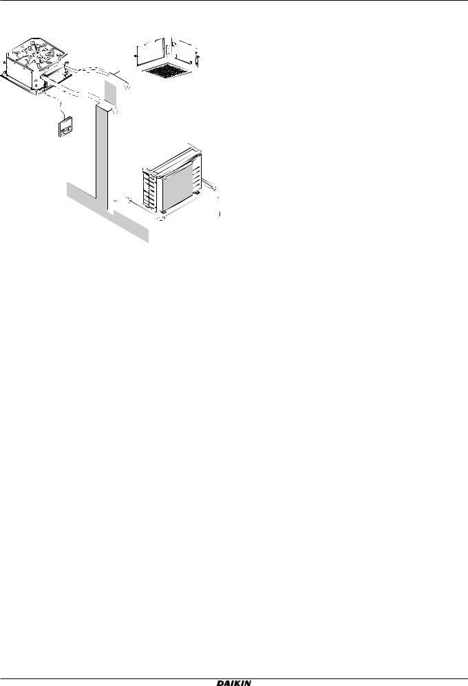
5 Preparation
4.4System layout
|
a |
|
|
f |
|
g |
e |
i |
|
d |
|
|
b |
|
c
h
aIndoor unit
bOutdoor unit
cUser interface
dSuction air
eDischarge air
fRefrigerant piping + interconnection cable
gDrain pipe
hEarth wiring
iSuction grille and air filter
4.5Combining units and options
4.5.1Possible options for the indoor unit
Make sure you have the following mandatory options:
▪User interface: Wired or wireless
▪Decoration panel: Standard or self-cleaning
5 Preparation
5.1Overview: Preparation
This chapter describes what you have to do and know before going on-site.
It contains information about:
▪Preparing the installation site
▪Preparing the refrigerant piping
▪Preparing the electrical wiring
5.2Preparing the installation site
Do NOT install the unit in places often used as work place. In case of construction works (e.g. grinding works) where a lot of dust is created, the unit MUST be covered.
Choose an installation location with sufficient space for carrying the unit in and out of the site.
5.2.1Installation site requirements of the indoor unit
INFORMATION
Also read the following requirements:
▪General installation site requirements. See the "General safety precautions" chapter.
▪Refrigerant piping requirements (length, height difference). See further in this "Preparation" chapter.
INFORMATION
The sound pressure level is less than 70 dBA.
CAUTION
Appliance not accessible to the general public, install it in a secured area, protected from easy access.
This unit, both indoor and outdoor, is suitable for installation in a commercial and light industrial environment.
NOTICE
The equipment described in this manual may cause electronic noise generated from radio-frequency energy. The equipment complies to specifications that are designed to provide reasonable protection against such interference. However, there is no guarantee that interference will not occur in a particular installation.
It is therefore recommended to install the equipment and electric wires keeping proper distances away from stereo equipment, personal computers, etc.
f e |
d |
a |
|
|
|
|
|
b |
| <![if ! IE]> <![endif]>1000 |
<![if ! IE]> <![endif]>1000≥ |
|
| <![if ! IE]> <![endif]>≥ |
|
c |
|
≥1500 |
|
|
≥1500 |
|
(mm)
aEarth leakage protector
bFuse
cOutdoor unit
dIndoor unit
eUser interface
fPersonal computer or radio
In places with weak reception, keep distances of 3 m or more to avoid electromagnetic disturbance of other equipment and use conduit tubes for power and transmission lines.
▪Fluorescent lights. When installing a wireless user interface in a room with fluorescent lights, mind the following to avoid interference:
▪Install the wireless user interface as close as possible to the indoor unit.
▪Install the indoor unit as far as possible from the fluorescent lights.
▪Take care that in the event of a water leak, water cannot cause any damage to the installation space and surroundings.
▪Choose a location where the hot/cold air discharged from the unit or the operation noise, will NOT disturb anyone.
▪Air flow. Make sure nothing blocks the air flow.
▪Drainage. Make sure condensation water can be evacuated
properly.
Installer and user reference guide |
FFA25~60A2VEB(9) |
10 |
Split system air conditioners |
4P550955-4 – 2018.08 |
Loading...