


 Loading...
Private Communication Systems
Mobile Phones
Service Manual
for
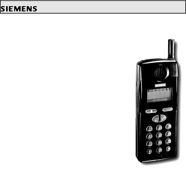
C10 / C11 / C12
V 1.0
Service Manual C1x |
V 1.0 |
PN MP ST |
|
Page 1 of 23 |
R. Fleuren |
Sm_C1x_lvl2_v10_w97.doc |
09/98 |

Private Communication Systems
Mobile Phones
1Table of Contents
1 TABLE OF CONTENTS .................................................................................................................................... |
2 |
|
2 TECHNICAL DATA ........................................................................................................................................... |
3 |
|
3 GENERAL INFORMATION ............................................................................................................................. |
3 |
|
4 MECHANICAL CONCEPT ............................................................................................................................... |
4 |
|
4.1 |
C1X MECHANICAL DRAWING............................................................................................................................. |
4 |
4.2N ECESSARY TOOLS ........................................................................................................................................... |
6 |
|
4.3 |
DISASSEMBLING THE C1X................................................................................................................................ |
6 |
4.4 |
ASSEMBLING THE C1X.................................................................................................................................... |
9 |
4.5 |
HANDSET DATECODES................................................................................................................................... |
12 |
5 HARDWARE CONCEPT |
|
|
................................................................................................................................................................................. |
|
12 |
5.1 |
BLOCK DIAGRAM.......................................................................................................................................... |
12 |
5.2 |
HARDWARE DESCRIPTION............................................................................................................................... |
14 |
5.3 |
POWER SUPPLY CONCEPT............................................................................................................................... |
14 |
5.4 |
OVERVOLTAGE CONDITIONS ........................................................................................................................... |
16 |
6 SOFTWARE PROGRAMMING ..................................................................................................................... |
17 |
|
6.1 |
DESCRIPTION OF SOFTWARE BOOTING |
|
....................................................................................................................................................................... |
|
17 |
6.2 |
LANGUAGE GROUPS...................................................................................................................................... |
17 |
7 BATTERY .......................................................................................................................................................... |
18 |
|
7.1 |
SPECIFICATION.............................................................................................................................................. |
18 |
7.2 |
CHARGING................................................................................................................................................... |
19 |
7.3 |
SHORT CIRCUIT PROTECTION........................................................................................................................... |
19 |
7.4 |
DEEP DISCHARGE......................................................................................................................................... |
20 |
7.5B ATTERY D ATECODES ..................................................................................................................................... |
21 |
|
8 UNBLOCKING ................................................................................................................................................. |
22 |
|
8.1 |
SIEMENS HOTLINE......................................................................................................................................... |
22 |
8.2 |
INTERNET SOLUTION....................................................................................................................................... |
23 |
Service Manual C1x |
V 1.0 |
PN MP ST |
|
Page 2 of 23 |
R. Fleuren |
Sm_C1x_lvl2_v10_w97.doc |
09/98 |
Private Communication Systems
Mobile Phones
2 |
Technical Data |
|
|
|
Length: |
137 mm |
|
|
|
Width: |
55 mm |
|
|
|
Thickness: |
22 mm |
|
|
|
Volume: |
149 cm³ |
|
|
|
Weight: |
165 g |
|
|
|
Standards: |
GSM Phase 2 |
|
||
Performance: |
C10: GSM |
900, |
Class 4 (2 Watt) |
|
|
|
C11: GSM 1800, |
Class 1 (1 Watt) |
|
|
|
C12: GSM 1900, |
Class 1 (1 Watt) |
|
Power supply: |
NiMH 700 mAh |
|
||
Standby time: |
Up to 80 hours |
|
||
Talk time: |
Up to 5 hours. |
|
||
Charging time: |
up to 7 hours (with Standard |
|||
Charger) |
up to 1.5 hours (with Rapid Charger, optional) |
|||
|
|
|||
Display: |
3 lines of 12 characters each |
|||
|
|
+ 1 dedicated icon-line |
||
SIM Card Type: |
Plug-In, 3V or 5V |
|
||
Antenna: |
Non-retractable, Lambda/2 helix type |
|||
Accessories: |
|
|
|
|
|
a) Standard: |
Standard Charger, Battery (3.6V, 700mAh) |
||
|
bI Optional: |
Spare Battery, Rapid Charger, Desk Top Charger, Belt Clip, |
||
|
|
Portable |
Handsfree, Car Accessories, Travel Charger |
|
3General Information
Service Manual C1x |
V 1.0 |
PN MP ST |
|
Page 3 of 23 |
R. Fleuren |
Sm_C1x_lvl2_v10_w97.doc |
09/98 |
Private Communication Systems
Mobile Phones
With the C1x (C10, C11 and C12) the first series of the new C class of Siemens Mobiles are offered to the customer. The intention of this class is to offer entry-level mobile phones for the mass consumer market.
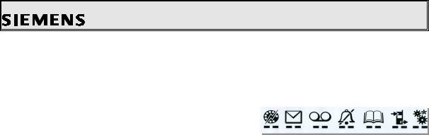
One of the main differences is the new type of display used: It is an alphanumeric |
|
display which offers 3 lines of text (12 characters |
|
each) plus a dedicated icon-line to access the |
|
different menues. |
Quick-Dial- SMS Voicemail Ringer Phonebook Call List Setup |
|
List |
4Mechanical Concept
Note: All part numbers refer to mechanical drawing in section 4.1!
The mechanical concept of the C1x mobiles is similar to the one of S6 and E10.
The C1x consists of two boards, the RF & Control module (1000) and the user interface (MMI board, 1010).
The connection between these two boards is not established by a normal connector with plug-in contacts, but by a special interconnector (1210) embedded into a shielding frame (1080). This interconnector is upholding the connection through the pressure implied on it by the housing.
Caution: Be careful when assembling the interconnector. Avoid any kind of dust or dirt because it will affect the contacts of the interconnector.
On the MMI board there are no exchangeable components. In opposite to the MMI board of S6 and E10 there is no ringer on the MMI. The ringer (1220) is placed in the shielding cover (1090) and connected to the RF&Control module (1000) by a plug and a cable.
Because the Molex connector is not located at the bottom of the telephone but on it’s top, there is no need anymore for RF cable mounted to the MMI board and for a RF plug neither.
The antenna (1150) is not screwed into the lower case shell, but it is a plug-in type. The keypad (1050), the loudspeaker (1140), the microphone (1130), the dust protection frame (1070) and the display window (1060) are mounted into the upper case shell (1020). Make sure that the microphone contact springs are not damaged when mounting.
When turning in the screws (1160 and 1170) make sure that the right torque is used (0.25 0.05)Nm, because this will have an effect on the contacts of the interconnector.
4.1C1X mechanical drawing
Service Manual C1x |
V 1.0 |
PN MP ST |
|
Page 4 of 23 |
R. Fleuren |
Sm_C1x_lvl2_v10_w97.doc |
09/98 |

Private Communication Systems
Mobile Phones
Note: The numbers shown above are NO ordering numbers. Use the numbers supplied by your service manager for ordering!
Service Manual C1x |
V 1.0 |
PN MP ST |
|
Page 5 of 23 |
R. Fleuren |
Sm_C1x_lvl2_v10_w97.doc |
09/98 |
Private Communication Systems
Mobile Phones
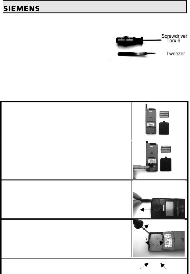
4.2Necessary tools
For disassembling the SL10 the following tools are mandatory:
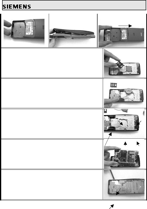
4.3Disassembling the C1X
Attention: ESD regulations have to be followed!
1.First remove the battery lid and the battery below it.
2.Remove the SIM card rack with the SIM card.
3.Then you pull the antenna out and remove the connector cover.
4.Remove the four cylinder-head screws in the battery
compartment.
5.Release the catches in the battery compartment, lift the lower housing section and push it forwards and out (see figures below).
Service Manual C1x |
V 1.0 |
PN MP ST |
|
Page 6 of 23 |
R. Fleuren |
Sm_C1x_lvl2_v10_w97.doc |
09/98 |
Private Communication Systems
Mobile Phones
6.Remove the card reader from the recess in the sreen lid.
7.Then loosen the ringer plug-in connector on the radio and control module and remove the ringer afterwards.
8.Unscrew the five cylinder-head screws in the screen lid and remove the screen lid.
9.Remove the RFand control modul.
10.Remove the battery contacts.
Service Manual C1x |
V 1.0 |
PN MP ST |
|
Page 7 of 23 |
R. Fleuren |
Sm_C1x_lvl2_v10_w97.doc |
09/98 |
Loading...