


PNOZ m B0
Configurable Control System PNOZmulti
Operating Manual1002660EN03
This document is a translation of the original document.
All rights to this documentation are reserved by Pilz GmbH & Co. KG. Copies may be made for internal purposes. Suggestions and comments for improving this documentation will be gratefully received.
Pilz®, PIT®, PMI®, PNOZ®, Primo®, PSEN®, PSS®, PVIS®, SafetyBUS p®, SafetyEYE®, SafetyNET p®, the spirit of safety® are registered and protected trademarks of Pilz GmbH & Co. KG in some countries.
 SD means Secure Digital

Content
Section 1 |
Introduction |
5 |
|
|
1.1 |
Validity of documentation |
5 |
|
1.2 |
Retaining the documentation |
5 |
|
1.3 |
Definition of symbols |
5 |
Section 2 |
Overview |
7 |
|
|
2.1 |
Range |
7 |
|
2.2 |
Unit features |
7 |
|
2.3 |
Chip card |
8 |
|
2.4 |
Front view |
9 |
Section 3 |
Safety |
|
10 |
|
3.1 |
Intended use |
10 |
|
3.2 |
System requirements |
10 |
|
3.3 |
Safety regulations |
10 |
|
3.3.1 |
Use of qualified personnel |
10 |
|
3.3.2 |
Warranty and liability |
11 |
|
3.3.3 |
Disposal |
11 |
|
3.3.4 |
For your safety |
11 |
Section 4 |
Function description |
12 |
|
|
4.1 |
Integrated protection mechanisms |
12 |
|
4.2 |
Functions |
12 |
|
4.3 |
System reaction time |
12 |
|
4.4 |
Block diagram |
12 |
|
4.5 |
Diagnostics |
13 |
Section 5 |
Installation |
14 |
|
|
5.1 |
Install base unit without expansion module |
14 |
|
5.2 |
Control cabinet installation |
14 |
|
5.2.1 |
Dimensions |
15 |
|
5.2.2 |
Mounting distances |
15 |
|
5.3 |
Connecting the base unit and expansion modules |
16 |
Section 6 |
Commissioning |
17 |
|
|
6.1 |
Wiring |
17 |
|
6.2 |
Commissioning the control system |
17 |
|
6.2.1 |
Load project from chip card |
18 |
|
6.2.2 |
Load project via USB port |
18 |
|
6.3 |
Connection |
19 |
|
6.4 |
Function test during commissioning |
21 |
|
6.5 |
Using the chip card |
21 |
|
6.6 |
Connection example |
23 |
Section 7 |
Operation |
24 |
||
|
|
7.1 |
LED messages |
24 |
|
|
7.2 |
Display messages |
25 |
|
|
7.2.1 |
Rotary knob |
27 |
|
|
|
|
|
Operating Manual PNOZ m B0 |
|
3 |
||
1002660EN03 |
|
|
|
|

Content
|
7.2.1.1 |
Function |
27 |
|
7.2.1.2 |
Pull out and retract the knob |
27 |
|
7.2.1.3 |
Rotate and press the knob |
27 |
|
7.2.2 |
Switch between menu levels |
28 |
|
7.2.3 |
Unit diagnostics on the LC display |
28 |
|
7.2.4 |
Error stack on the LC display |
29 |
|
|
|
|
Section 8 |
Technical details |
31 |
|
|
8.1 |
Safety characteristic data |
35 |
|
|
|
|
Section 9 |
Supplementary data |
36 |
|
|
9.1 |
Maximum capacitive load C (μF) with load current I (A) at the semicon |
36 |
|
|
ductor outputs |
|
|
9.2 |
Maximum permitted total current of the semiconductor outputs |
36 |
|
9.3 |
Maximum permitted humidity |
37 |
|
9.3.1 |
Max. relative humidity, operation |
37 |
|
9.3.2 |
Max. relative humidity, storage |
37 |
|
|
|
|
Section 10 |
Order reference |
38 |
|
Operating Manual PNOZ m B0 |
4 |
1002660EN03 |
|
Introduction
1 Introduction
1.1Validity of documentation
This documentation is valid for the product PNOZ m B0. It is valid until new documentation is published.
This operating manual explains the function and operation, describes the installation and provides guidelines on how to connect the product.
1.2Retaining the documentation
This documentation is intended for instruction and should be retained for future reference.
1.3Definition of symbols
Information that is particularly important is identified as follows:
DANGER!
This warning must be heeded! It warns of a hazardous situation that poses an immediate threat of serious injury and death and indicates preventive measures that can be taken.
WARNING!
This warning must be heeded! It warns of a hazardous situation that could lead to serious injury and death and indicates preventive measures that can be taken.
CAUTION!
This refers to a hazard that can lead to a less serious or minor injury plus material damage, and also provides information on preventive measures that can be taken.
NOTICE
This describes a situation in which the product or devices could be dam aged and also provides information on preventive measures that can be taken. It also highlights areas within the text that are of particular import ance.
Operating Manual PNOZ m B0 |
5 |
1002660EN03 |
|

Introduction
INFORMATION
This gives advice on applications and provides information on special fea tures.
Operating Manual PNOZ m B0 |
6 |
1002660EN03 |
|

Overview
2 Overview
2.1Range
}Base unit PNOZ m B0
}Terminator
}Documentation on data medium
2.2Unit features
Using the product PNOZ m B0:
Base unit of the configurable control system PNOZmulti 2
The product has the following features:
}Can be configured in the PNOZmulti Configurator
}Semiconductor outputs: 4 safety outputs
Depending on the application, up to PL e of EN ISO 138491 and up to SIL CL 3 of EN IEC 62061
}12 inputs for connecting, for example:
–Emergency stop pushbuttons
–Twohand pushbuttons
–Safety gate limit switches
–Reset buttons
–Light beam devices
–Scanners
–Enabling switches
–PSEN
–Operating mode selector switches
}8 configurable inputs/outputs Can be configured as:
–Inputs (see above for connection options)
or
–Auxiliary outputs
}4 configurable outputs Can be configured as:
–Auxiliary outputs
or
–Test pulse outputs
}LED for:
–Error messages
–Diagnostics
Operating Manual PNOZ m B0 |
7 |
1002660EN03 |
|

Overview
–Supply voltage
–Fault at the outputs
–Fault at the inputs
}Backlit display for:
–Error messages
–State of supply voltage
–State of inputs/outputs
–Status information
–Device information
}Test pulse outputs used to monitor shorts across the inputs
}Monitoring of shorts between the safety outputs
}Plugin connection terminals:
Either springloaded terminal or screw terminal available as an accessory (see order reference)
}Rotary knob for menu control
}Expansion modules can be connected
(please refer to the document "PNOZmulti System Expansion" for details of the type and number that can be connected)
2.3Chip card
To be able to use the product you will need a chip card.
Chip cards are available with memories of 8 kByte and 32 kByte. For largescale projects we recommend the 32 kByte chip card (see Technical Catalogue: Accessories chapter).
Operating Manual PNOZ m B0 |
8 |
1002660EN03 |
|

Overview
2.4Front view
X3 |
IM0 IM1 |
IM2 |
IM3 I4 |
I5 |
I6 |
I7 |
||
X1 |
I8 |
I9 |
I10 |
I11 |
I12 |
I13 |
I14 |
I15 |
PNOZ m B0 |
|
|
|
|
|
|
||
X2 T0M20 T1M21 T2M22 T3M23 O0 |
O1 |
O2 |
O3 |
|||||
X4 IM16 IM17 IM18 IM19 A1 |
A2 |
0 V |
24 V |
|||||
X3 IM0 IM1 |
IM2 |
IM3 I4 |
I5 |
I6 |
I7 |
||
X1 I8 |
I9 |
I10 |
I11 |
I12 |
I13 |
I14 |
I15 |
PNOZ m B0 |
|
|
|
|
|
|
|
X2 T0M20 T1M21 T2M22 T3M23 O0 |
O1 |
O2 |
O3 |
||||
X4 IM16 IM17 IM18 IM19 A1 |
A2 |
0 V |
24 V |
||||
Fig.: Front view with and without cover
Legend
}X1:
–Inputs I8 ... I15
}X2:
–Configurable test pulse/auxiliary outputs T0M20 ... T3M23
–Semiconductor outputs O0 ... O3
}X3:
–Configurable inputs/outputs IM0 – IM3
–Inputs I4 ... I7
}X4:
–Configurable inputs/outputs IM16 – IM19
–Supply connections
}LEDs:
–POWER
–RUN
–DIAG
–FAULT
–I FAULT, OFAULT
Operating Manual PNOZ m B0 |
9 |
1002660EN03 |
|
Safety
3 Safety
3.1Intended use
The configurable control system PNOZmulti 2 is used for the safetyrelated interruption of safety circuits and is designed for use in:
}ESTOP equipment
}Safety circuits in accordance with VDE 0113 Part 1 and EN 602041
CAUTION!
Inputs and outputs for standard functions must not be used for safetyre lated applications.
Intended use includes making the electrical installation EMCcompliant. The product is de signed for use in an industrial environment. It is not suitable for use in a domestic environ ment, as this can lead to interference.
The following is deemed improper use in particular:
}Any component, technical or electrical modification to the product
}Use of the product outside the areas described in this manual
}Use of the product outside the technical details (see chapter entitled “Technical De tails”)
3.2System requirements
Please refer to the "Product Modifications" document in the "Version overview" section for details of which versions of the PNOZmulti Configurator can be used for this product.
3.3Safety regulations
3.3.1Use of qualified personnel
The products may only be assembled, installed, programmed, commissioned, operated, maintained and decommissioned by competent persons.
A competent person is someone who, because of their training, experience and current pro fessional activity, has the specialist knowledge required to test, assess and operate the work equipment, devices, systems, plant and machinery in accordance with the general standards and guidelines for safety technology.
It is the company’s responsibility only to employ personnel who:
}Are familiar with the basic regulations concerning health and safety / accident preven tion
}Have read and understood the information provided in this description under "Safety"
}And have a good knowledge of the generic and specialist standards applicable to the specific application.
Operating Manual PNOZ m B0 |
10 |
1002660EN03 |
|
Safety
3.3.2Warranty and liability
All claims to warranty and liability will be rendered invalid if
}The product was used contrary to the purpose for which it is intended
}Damage can be attributed to not having followed the guidelines in the manual
}Operating personnel are not suitably qualified
}Any type of modification has been made (e.g. exchanging components on the PCB boards, soldering work etc.).
3.3.3Disposal
}In safetyrelated applications, please comply with the mission time tM in the safetyre lated characteristic data.
}When decommissioning, please comply with local regulations regarding the disposal of electronic devices (e.g. Electrical and Electronic Equipment Act).
3.3.4For your safety
The unit meets all the necessary conditions for safe operation. However, you should always ensure that the following safety requirements are met:
}Adequate protection must be provided for all inductive consumers.
}Do not open the housing or make any unauthorised modifications.
}Please make sure you shut down the supply voltage when performing maintenance work (e.g. exchanging contactors).
Operating Manual PNOZ m B0 |
11 |
1002660EN03 |
|
Function description
4 |
Function description |
4.1Integrated protection mechanisms
The relay conforms to the following safety criteria:
}The circuit is redundant with builtin selfmonitoring.
}The safety function remains effective in the case of a component failure.
}The safety outputs are tested periodically using a disconnection test.
4.2Functions
The function of the inputs and outputs on the control system depends on the safety circuit created using the PNOZmulti Configurator. A chip card is used to download the safety cir cuit to the base unit. The base unit has 2 microcontrollers that monitor each other. They evaluate the input circuits on the base unit and expansion modules and switch the outputs on the base unit and expansion modules accordingly.
The LEDs on the base unit and expansion modules indicate the status of the configurable control system PNOZmulti.
The online help on the PNOZmulti Configurator contains descriptions of the operating modes and all the functions of the control system, plus connection examples.
4.3System reaction time
Calculation of the maximum reaction time between an input switching off and a linked out put in the system switching off is described in the document "System Expansion".
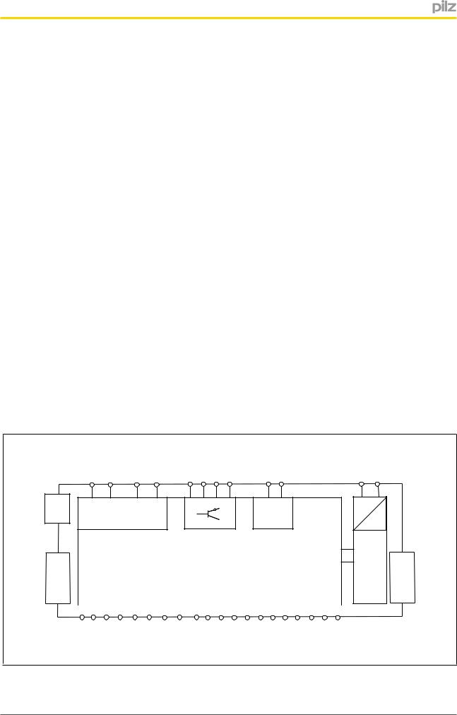
4.4Block diagram
T0M20 T2M22
T1M21 |
T3M23 O0 O1 O2 O3 |
24 V 0 V |
USB |
Configurable |
24 V |
0 V |
|
|||
|
output |
|
|
Interface extension module |
|
|
|
|
|
|
|
|
|
|
|
|
|
|
|
|
|
|
|
|
|
|
|
|
|
input/output |
|
|
|
|
|
|
|
Input |
|||||||||||
|
|
|
|
Configurable |
|
|
|
|
|
|
|
|
|
|
|
|
|
|
|
|||
|
|
|
|
|
|
|
|
|
|
|
|
|
|
|
|
|
|
|
|
|
|
|
|
|
|
|
|
|
|
|
|
|
|
|
|
|
|
|
|
|
|
|
|
|
|
A1 A2
= |
|
= |
|
Power |
Interface extension module |
|
IM0 |
IM2 |
IM16 |
IM18 |
I4 I5 I6 I7 I8 I9 I10 I11 I12 I13 I14 I15 |
|
|
IM1 |
IM3 |
IM17 |
IM19 |
|
Operating Manual PNOZ m B0 |
12 |
1002660EN03 |
|
 Loading...