


SC-HT878

GCSEB
E
GC GN
GS
EE
RQT7429-2B
Operating Instructions
DVD Home Theater Sound System
Model No. SC-HT878/SC-HT870
SC-HT520
The illustration shows SC-HT520 for the United
Kingdom and Continental Europe.
Before connecting, operating or adjusting this product,
please read these instructions completely.
Please keep this manual for future reference.
Region number
The player plays DVD-Video marked with labels containing the
region number or “ALL”.
Example: [The\United\Kingdom\and\Continental\Europe[
[Note[
“EB” on the packaging indicates the United Kingdom.
Region Number
The United Kingdom, Continental Europe, the
Middle East, South Africa, Saudi Arabia and
Kuwait
2
Southeast Asia 3
Australia and N.Z. 4
Russia 5
2 ALL
3
5
2
Table of contents
Caution for AC Mains Lead. . . . . . . . . . . . . . . . . . 3
Accessories . . . . . . . . . . . . . . . . . . . . . . . . . . . . . . 3
Control reference guide . . . . . . . . . . . . . . . . . . . 14
Discs that can be played/Disc handling . . . . . . 15
Convenient functions . . . . . . . . . . . . . . . . . . . . . 18
Position memory/Zoom/Audio/Subtitle/
Quick replay/Page skip/Repeat play/
All group, random and program play
Using navigation menus . . . . . . . . . . . . . . . . . . . 20
Playing data discs/Playing HighMAT
TM
discs/Playing
the programs/Playing a play list
Using on-screen menus . . . . . . . . . . . . . . . . . . . 22
Changing the player settings . . . . . . . . . . . . . . . 24
The radio. . . . . . . . . . . . . . . . . . . . . . . . . . . . . . . . 26
Automatic presetting/Selecting the preset channels/
Manual tuning/RDS broadcasting/Optional antenna
connections
Sound field and sound quality . . . . . . . . . . . .28-30
Sound Field Control/Super Surround/Center Focus/
Dolby Pro Logic II/Speaker level adjustments/Down-
mixing/Subwoofer level/Custom Sound Memory
Other functions . . . . . . . . . . . . . . . . . . . . . . . . . . 31
Sleep timer/Enjoying Karaoke/Muting/
Using headphones
Operating other equipment. . . . . . . . . . . . . . . . . 32
Safety precautions. . . . . . . . . . . . . . . . . . . . . . . . 34
Maintenance. . . . . . . . . . . . . . . . . . . . . . . . . . . . . 34
Language code list . . . . . . . . . . . . . . . . . . . . . . . 34
Glossary . . . . . . . . . . . . . . . . . . . . . . . . . . . . . . . . 35
Specifications . . . . . . . . . . . . . . . . . . . . . . . . . . . 36
Troubleshooting guide . . . . . . . . . . . . . . . . . . . . 38
Getting started
Simple setup
STEP 1 Front and surround speaker
assembly. . . . . . . . . . . . . . . . . . . . . . . 4
Other speaker setup options . . . . . . 7
STEP 2 Locating . . . . . . . . . . . . . . . . . . . . . . . 8
STEP 3 Connecting speakers with the
subwoofer . . . . . . . . . . . . . . . . . . . . . 10
STEP 4 Video connections . . . . . . . . . . . . . . 12
STEP 5 Radio and system connection . . . . 13
STEP 6 The remote control. . . . . . . . . . . . . . 13
STEP 7 QUICK SETUP. . . . . . . . . . . . . . . . . . 14
Disc operations
Basic play . . . . . . . . . . . . . . . . . . . . . . . . . . . . . 16
Other operations
Reference

2
RQT7429
Dear customer
Thank you for purchasing this product. For optimum performance
and safety, please read these instructions carefully.
[HT878]: indicates features applicable to SC-HT878 only.
[HT870]: SC-HT870 only.
[HT520]: SC-HT520 only.
≥These operating instructions are applicable to models
SC-HT878, SC-HT870 and SC-HT520 for a variety of
regions.
≥Unless otherwise indicated, illustrations in these
operating instructions are of SC-HT520 for the United
Kingdom and Continental Europe.
≥Operations in these instructions are described mainly
with the remote control, but you can do the operations on
the main unit if the controls are the same.
System SC-HT878 SC-HT870 SC-HT520
Main unit SA-HT878 SA-HT870 SA-HT520
Front speakers SB-FS878 SB-PF921 SB-FS520
Center speaker SB-PC878 SB-PC920 SB-PC520
Surround speakers SB-FS878 SB-PS921 SB-FS520
Active subwoofer SB-WA878 SB-WA870 SB-WA520
CAUTION!
THIS PRODUCT UTILIZES A LASER.
USE OF CONTROLS OR ADJUSTMENTS OR PERFORMANCE
OF PROCEDURES OTHER THAN THOSE SPECIFIED HEREIN
MAY RESULT IN HAZARDOUS RADIATION EXPOSURE.
DO NOT OPEN COVERS AND DO NOT REPAIR YOURSELF.
REFER SERVICING TO QUALIFIED PERSONNEL.
WARNING:
TO REDUCE THE RISK OF FIRE, ELECTRIC SHOCK OR
PRODUCT DAMAGE, DO NOT EXPOSE THIS APPARATUS
TO RAIN, MOISTURE, DRIPPING OR SPLASHING AND THAT
NO OBJECTS FILLED WITH LIQUIDS, SUCH AS VASES,
SHALL BE PLACED ON THE APPARATUS.
CAUTION!
≥DO NOT INSTALL OR PLACE THIS UNIT IN A BOOKCASE,
BUILT-IN CABINET OR IN ANOTHER CONFINED SPACE.
ENSURE THE UNIT IS WELL VENTILATED. TO PREVENT
RISK OF ELECTRIC SHOCK OR FIRE HAZARD DUE TO
OVERHEATING, ENSURE THAT CURTAINS AND ANY
OTHER MATERIALS DO NOT OBSTRUCT THE
VENTILATION VENTS.
≥DO NOT OBSTRUCT THE UNIT’S VENTILATION OPENINGS
WITH NEWSPAPERS, TABLECLOTHS, CURTAINS, AND
SIMILAR ITEMS.
≥DO NOT PLACE SOURCES OF NAKED FLAMES, SUCH AS
LIGHTED CANDLES, ON THE UNIT.
≥DISPOSE OF BATTERIES IN AN ENVIRONMENTALLY
FRIENDLY MANNER.
For the Middle East, South Africa, Southeast Asia, Saudi
Arabia and Kuwait
THIS UNIT IS INTENDED FOR USE IN TROPICAL CLIMATES.
For the United Kingdom, Continental Europe, Australia, N.Z.
and Russia
THIS UNIT IS INTENDED FOR USE IN MODERATE CLIMATES.
The socket outlet shall be installed near the equipment and
easily accessible or the mains plug or an appliance coupler shall
remain readily operable.
This product may receive radio interference caused by mobile
telephones during use. If such interference is apparent, please
increase separation between the product and the mobile
telephone.
(Inside of product)
(Produktets innside)
(Tuotteen sisällä)
LUOKAN 1 LASERLAITE
KLASS 1 LASER APPARAT
CLASS 1
LASER PRODUCT
(Back of product)

3
RQT7429
Caution for AC Mains Lead/Accessories
Caution for AC Mains Lead
(For United Kingdom, Saudi Arabia
and Kuwait)
(“EB” and “GS” area code models only)
For your safety, please read the following text carefully.
This appliance is supplied with a moulded three pin mains plug for
your safety and convenience.
A 5-ampere fuse is fitted in this plug.
Should the fuse need to be replaced please ensure that the
replacement fuse has a rating of 5-ampere and that it is approved by
ASTA or BSI to BS1362.
Check for the ASTA mark Ï or the BSI mark Ì on the body of the
fuse.
If the plug contains a removable fuse cover you must ensure that it is
refitted when the fuse is replaced.
If you lose the fuse cover the plug must not be used until a
replacement cover is obtained.
A replacement fuse cover can be purchased from your local dealer.
If a new plug is to be fitted please observe the wiring code as stated
below.
If in any doubt please consult a qualified electrician.
IMPORTANT
The wires in this mains lead are coloured in accordance with the
following code:
Blue: Neutral, Brown: Live.
As these colours may not correspond with the coloured markings
identifying the terminals in your plug, proceed as follows:
The wire which is coloured Blue must be connected to the terminal
which is marked with the letter N or coloured Black or Blue.
The wire which is coloured Brown must be connected to the terminal
which is marked with the letter L or coloured Brown or Red.
WARNING: DO NOT CONNECT EITHER WIRE TO THE
EARTH TERMINAL WHICH IS MARKED WITH THE
LETTER E, BY THE EARTH SYMBOL Ó OR COLOURED
GREEN OR GREEN/YELLOW.
THIS PLUG IS NOT WATERPROOF—KEEP DRY.
Before use
Remove the connector cover.
How to replace the fuse
The location of the fuse differ according to the type of AC mains plug
(figures A and B). Confirm the AC mains plug fitted and follow the
instructions below.
Illustrations may differ from actual AC mains plug.
1. Open the fuse cover with a screwdriver.
2. Replace the fuse and close or attach the fuse cover.
CAUTION!
IF THE FITTED MOULDED PLUG IS UNSUITABLE FOR THE
SOCKET OUTLET IN YOUR HOME THEN THE FUSE SHOULD
BE REMOVED AND THE PLUG CUT OFF AND DISPOSED OF
SAFELY.
THERE IS A DANGER OF SEVERE ELECTRICAL SHOCK IF
THE CUT OFF PLUG IS INSERTED INTO ANY 13-AMPERE
SOCKET.
Fuse cover
Figure A
Figure B
Fuse
(5 ampere)
Fuse
(5 ampere)
Figure A
Figure B
Accessories
Please check and identify the supplied
accessories. Use numbers indicated in
parentheses when asking for replacement parts.
[Note]
The included AC mains lead is for use with this unit only.
Do not use it with other equipment.
\The\United\Kingdom\and\Republic\of\Ireland]
∏ 1 Remote control
[HT878] [HT870]
(EUR7722X30)
[HT520]
(EUR7722X10)
∏ 2 Remote control batteries
∏ 1 Video cable
(RJL1P016B15A)
∏ 1 AC mains lead
[The\United\Kingdom,[
[Saudi[Arabia]and[Kuwait]
(RJA0053-3X)
\Australia\and\N.Z.]
(K2CJ2DA00010)
[Continental[Europe,[Russia,[
[Southeast[Asia,[the[Middle[
[East,[South[Africa,[Saudi[
[Arabia[and[Kuwait]
(K2CQ2CA00002)
[The\United\Kingdom]
∏ 1 Antenna plug adaptor
(K1YZ02000013)
∏ 1 AM loop antenna
(N1DAAAA00001)
∏ 1 FM indoor antenna
(RSA0007-J)
∏ 1 System cable
(K1HA25HA0001)
∏ Speaker cables
[HT878] [HT520]
3k4-m cables
(REE1247A)
2k10-m cables
(REE1247C)
[HT870]
1k4-m cable (REE1203A)
∏ 1 Sheet of speaker-cable
stickers
∏ 8 Silver screws [HT878]
(XSN5+16FN)
∏ 4 Black screws [HT878]
(XTB3+10JFZ)
∏ 4 Clips [HT878]
(QWBG002AA)
∏
4 Large washer screws
[HT870]
(RHD50015)
∏ 8 Small screws [HT870]
(XSN5+10FN)
www.panasonic.co.uk (for UK customers only)
≥ Order accessory and consumable items for your
product with ease and confidence by telephoning our
Customer Care Centre Mon–Friday 9:00am–5:30pm.
(Excluding public holidays.)
≥ Or go on line through our Internet Accessor y ordering
application.
≥ Most major credit and debit cards accepted.
≥ All enquiries transactions and distribution facilities are
provided directly by Panasonic UK Ltd.
≥ It couldn’t be simpler!
Customer Care Centre
For UK customers: 08705 357357
For Republic of Ireland customers: 01 289 8333
Technical Support
For UK customers: 0870 1 505610
This Technical Support Hot Line number is for
Panasonic PC software related products only.
For Republic of Ireland, please use the Customer Care
Centre number listed above for all enquiries.
For all other product related enquiries, please use the
Customer Care Centre numbers listed above.

4
RQT7429
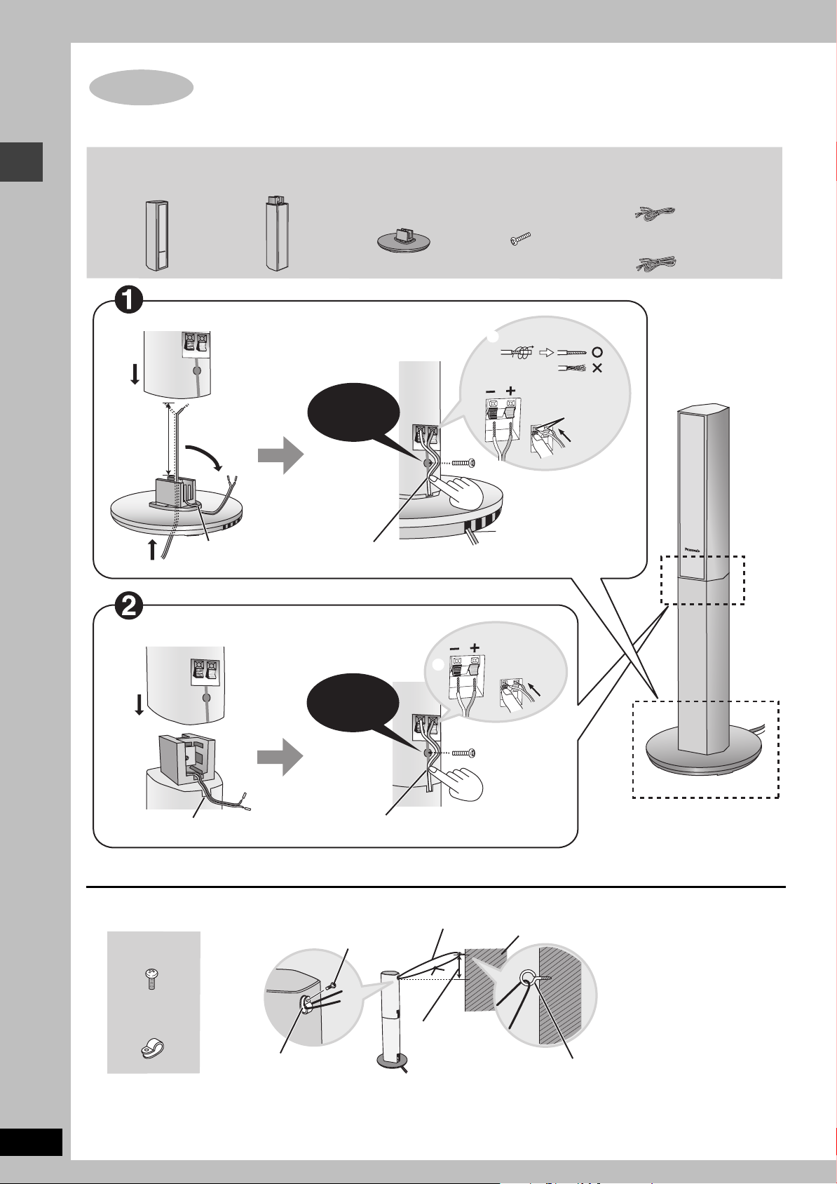
Front and surround speaker assembly
Simple setup
Front and surround speaker assembly
[Note]
The front and surround speaker pairs as well as the pipe pairs are
different.
– Check the label on the rear of the speaker before attaching the
pipe (‹ page 8).
– The pipe with the shorter cable is for the front speaker unit.
Preparation
≥To prevent damage or scratches, lay a soft cloth and perform
assembly on it.
≥For assembly, use a Phillips-head screwdriver.
1 Attach the pipe to the base.
1 Thread the speaker cable through the base.
2 Insert the pipe.
3 Secure the pipe to the
base.
Ensure the screw is
securely fastened.
2 Attach the stand to the front and
surround speaker.
≥
There is no difference between the right and left speakers and stands.
≥Using the polyfoam included with this unit may be convenient.
1 Remove the screw and separate the mounting plate into
two parts.
2 Attach the plate A to the speaker.
Ensure the plate A is fastened on straight by lightly tightening the
top and bottom screws alternately until fully tightened.
You can also attach to the upper rear of the speaker.
The height of the speaker is indicated in the diagram
(‹ page 5) when attaching the plate A to the upper rear or
lower rear of the speaker.
3 Place the pipe on the plate A and attach the plate B.
4 Secure the plate with the same screw removed in
procedure 1.
Make sure you have all the indicated components before starting the assembly, setup, and
connection.
4 pipes
4 large washer
screws
2 front and
2 surround
speaker units
8 small screws
4 bases
4 mounting plates
STEP1 [HT870]
The supplied stands are specially designed for attachment
to Panasonic SB-PF921 front speakers and SB-PS921
surround speakers. Only use as indicated in this setup.
Lessen excess speaker cable.
Thread the
speaker cable
through here.
Cable
Hole for screw
Groove
Insert the pipe while slightly
pulling on the speaker cable.
Rear side of base
Large
washer
screw
Cable
Plate A
Plate B
Small screw
Small screws
Speaker
Plate A
Polyfoam
Rotate the pipe so that the flat
side is facing away from the
back of the speaker.
Plate B
Fit the offset into the slot
and slide the plate B into
the locked position.
Offset
Slot
Plate B
Small screw

5
RQT7429
Front and surround speaker assembly
∫ Front and surround speaker height
(Assembled diagram)
3 Adjust the speaker height.
≥Check the screws you tightened on page 4.
e.g. Attaching the stand to the lower rear of the speaker
4 Connect the speaker cables.
5 Fasten the speaker cable to the base.
∫ Preventing the speakers from falling over (Front and surround speakers)
Preparation
Attach screw eyes (not included) to secure the speakers to the wall
(‹diagram right).
≥You will need to obtain the appropriate screw eyes to match the
walls and pillars to which the screw eyes are going to be
fastened.
≥Consult with a qualified housing contractor concerning the
appropriate procedure when attaching to a concrete wall or a
surface that may not have strong enough support. Improper
attachment may result in damage to the wall or speakers.
1 Thread the string (not included) through the slot on the
rear of the speaker to prevent it from falling over.
2 Loop the string through the screw eye and tie tightly.
For your reference
You can enjoy good acoustics by
adjusting the height of the speaker
with the height of the television so the
center positions of both are
approximately the same.
1,160 mm
Speaker
Pipe
Base
750 mm
818 mm
575 mm
704 mm
Stoppe
r
screw
Do not
remove.
You can adjust within this range.
Attach to lower
rear of speaker.
Attach to upper
rear of speaker.
Stopper screw
Screw to stop mounting plate from moving or
sliding below this point.
1 Loosen the attached speaker mounting
plate screw until the attached speaker is
slightly loose and adjustable.
Be careful not to loosen the screw too
much or the speaker may detach and fall.
2 With one hand on the base, and the other
holding the speaker, adjust the height of
the speaker up and down.
≥After adjusting the height, tighten the screw
on the mounting plate securely.
Phillips-head screwdriver
_: Copper
`: Silver
Push!
Rear speaker
panel
1 Twist off the vinyl ends of
the speaker cables.
2 Press the speaker cable into the groove.
If there is any excess speaker cable,
detach the rubber cap on the top of
the pipe and thread the speaker
cable into the opening while pulling
the speaker cable from the bottom of
the base.
Insert the wire
fully.
Rear side of base
Cable
1 Press the speaker
cable and thread
between the
hooks.
2 Fit the speaker
cable into the
base cover
groove as far as
possible.
String (not included)
Screw eye (not included)
Rear of the speaker
Approx. 150 mm
e.g.
Wall
6
RQT7429
Front and surround speaker assembly
Front and surround speaker assembly
≥You can attach the speakers directly to their bases (if you want to put them on shelves, for example).
∫ Preventing the speakers from falling over (Front and surround speakers)
[Note]
Consult with a qualified housing contractor concerning the appropriate procedure when attaching to a concrete wall or a surface that may not
have strong enough support. Improper attachment may result in damage to the wall or speakers.
STEP1 [HT878]
2
3
4
31
2
5
8
7
_:
`:
4
15
6
_:
`:
4 speaker units 4 stands
4 bases
Fit into groove.
Place into groove.
Position wire in
grooves as necessary,
avoiding knots.
Fit into groove.
Place into groove.
Confirm screw
is securely
fastened.
Confirm screw
is securely
fastened.
Approx.
120 mm
8 silver screws
Copper
Assembled
Copper
Silver
Silver
Insert the
wire fully.
Make sure you have all the indicated components before starting the assembly, setup, and connection.
4 black screws
4 clips
Black screw
Clip
Approx. 150 mm
String (not included)
Screw eye (not included)
Wall
4 speaker cables
≥2k4-m cables:
For front speakers
≥2k10-m cables:
For surround speakers
7
RQT7429
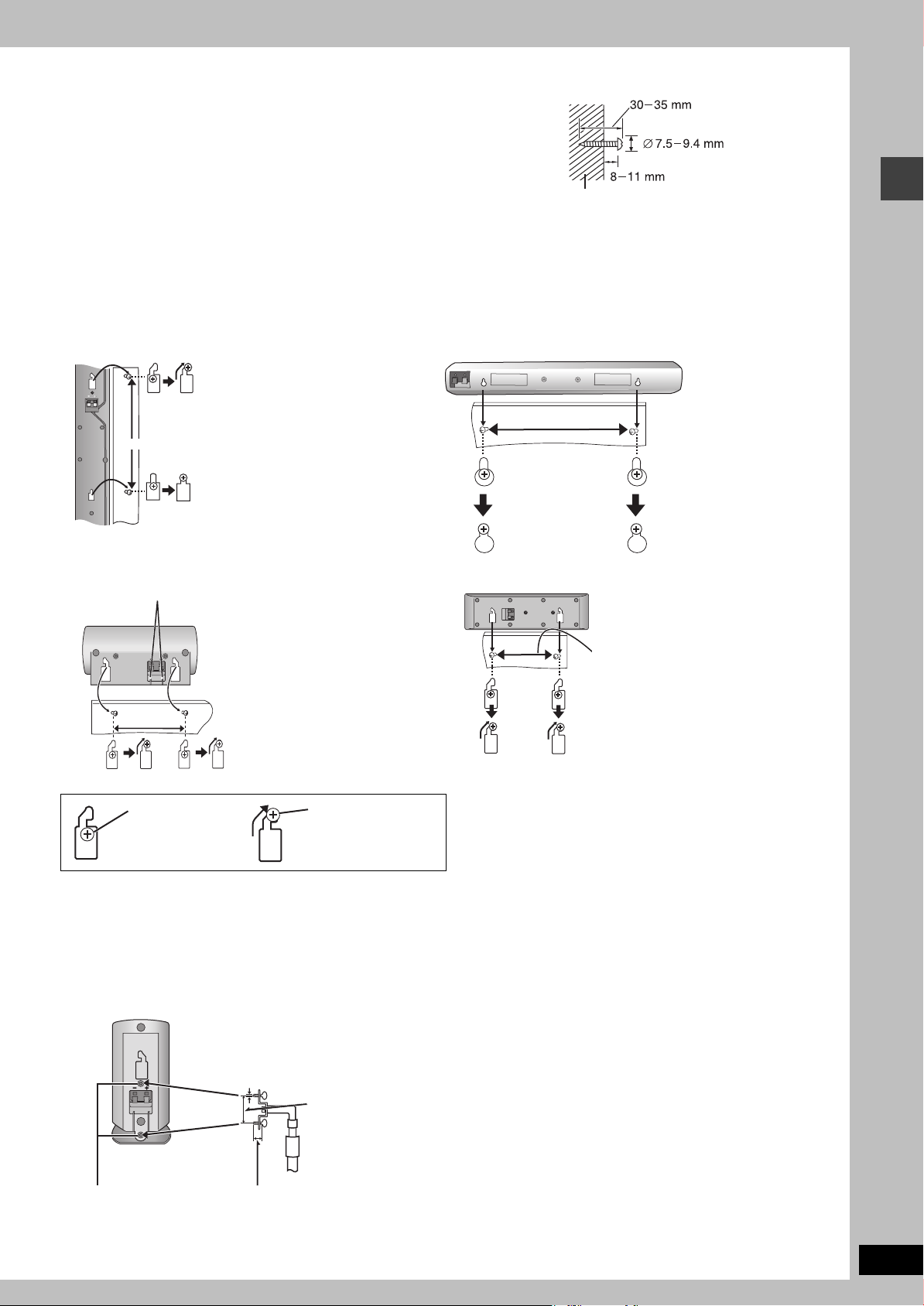
Other speaker setup options
Other speaker setup options
[HT878] (Center speaker only) [HT870] [HT520]
∫ Attaching to a wall
1 Drive a screw (not included) into a wall.
2 Fit the speaker securely onto the screw(s) with the hole(s).
≥The wall or pillar on which the speakers are to be attached should be capable of
supporting 10 kg per screw. Consult a qualified building contractor when attaching the
speakers to a wall. Improper attachment may result in damage to the wall and
speakers.
[HT870]
≥When mounting the front and surround speaker to a wall, we recommend using a string (not included) to prevent it from falling (‹ page 5).
≥Use of optional speaker cables are recommended for wall-mounted front and surround speakers. (You can also remove the speaker cables
from the pipes supplied with this system.)
∫ Fitting speaker stands (not included)
[HT878] [HT870] (Center speaker only)[HT520]
Ensure the stands meet these conditions before purchasing them.
Observe the diameter and length of the screws and the distance between screws as shown in the diagram.
≥The stands must be able to support over 10 kg.
≥The stands must be stable even if the speakers are in a high position.
e.g. [HT520] Front speaker
Wall or pillar
230 mm
Front and surround speakers [HT870]
Center speaker [HT878]
86 mm
So that the speaker fits up against the wall squarely, be
sure to press the speaker cable down into the groove.
Center speaker [HT520]
Center speaker [HT870]
150 mm
270 mm
In this position, the
speaker will likely
fall if moved to the
left or right.
Move the speaker so
that the screw is in
this position.
Attach the stands to
these metal screw
holes.
Plate thickness
plus 7 to 10 mm
5 mm, pitch 0.8 mm
60 mm
Speaker stand
(not included)

8
RQT7429
Locating
How you set up your speakers can a
ff
ect the bass and the sound
f
ield. Note the
f
ollowing points.
≥Place speakers on flat secure bases.
≥Placing speakers too close to floors, walls, and corners can result in excessive bass. Cover
walls and windows with thick curtains.
≥Place the front, center, and surround speakers at approximately the same distance from the
seating position. The angles in the diagrams are approximate.
STEP2 Locating
AC IN
Setup example
Main unit
[HT870]
SURROUND (L, R)
CENTER
SUBWOOFER
FRONT (L, R)
Do not use a front speaker as
a surround speaker or vice
versa. Verify the type of
speaker with the label on the
rear of the speaker.
Speaker labels
[HT878]
SURROUND (L, R) CENTER SUBWOOFERFRONT (L, R)
≥The front left, right and surround speakers are all the same.
Setup example
Main unit
≥The left and right speaker pairs are the same with respect to the front and surround
speakers.

9
RQT7429
Locating
≥Use only supplied speakers
Using other speakers can damage the unit and sound quality will
be negatively affected.
≥Set the speakers up on an even surface to prevent them from
falling. Take proper precautions to prevent the speakers from
falling if you cannot set them up on an even surface.
Main unit
[Note]
Keep your speakers at least 10 mm away from the system for
proper ventilation.
Center speaker
≥Vibration caused by the center speaker can disrupt the picture if it
is placed directly on the television. Put the center speaker on a
rack or shelf.
≥To prevent the speakers from falling, do not place directly on top
of the television.
Subwoofer
Place to the right or left of the television, on the floor or a sturdy
shelf so that it won’t cause vibration. Leave 10 cm at the rear for
ventilation.
Caution
Hold the speakers by the sides. Applying pressure to the front net
can damage the speaker.
Notes on speaker use
≥You can damage your speakers and shorten their useful life if you
play sound at high levels over extended periods.
≥Reduce the volume in the following cases to avoid damage.
– When playing distorted sound.
– When the speakers are receiving howling from a record player,
noise from FM broadcasts, or continuous signals from an
oscillator, test disc, or electronic instrument.
– When adjusting the sound quality.
– When turning the unit on or off.
12 3
4
Setup example
Main unit
[HT520]
FRONT
(L, R)
CENTER
SUBWOOFER
≥The front left, right and surround speakers are all the same.
SURROUND
(L, R)
e.g. [HT520]
If irregular coloring occurs on your television
The supplied speakers are designed to be used close to a
television, but the picture may be affected with some televisions
and setup combinations.
If this occurs, turn the television off for about 30 minutes.
The television’s demagnetizing function should correct the
problem. If it persists, move the speakers farther away from the
television.
Caution
≥The main unit and supplied speakers are to be used only
as indicated in this setup. Failure to do so may lead to
damage to the amplifier and/or the speakers, and may
result in the risk of fire. Consult a qualified service
person if damage has occurred or if you experience a
sudden change in performance.
≥Do not attempt to attach these speakers to walls using
methods other than those described in this manual.

10
RQT7429
Connecting speakers with the subwoofer
Attach the speaker-cable stickers to make connection easier.
\Note]
≥Never short-circuit positive (i) and negative (j) speaker wires.
≥Be sure to connect only positive (copper) wires to positive (i) terminals and negative (silver) wires to negative (j) terminals.
Incorrect connection can damage the speakers.
[HT878]
[HT870]
STEP3 Connecting speakers with the subwoofer
1
2
3
4
5
5 CENTER
4 SURROUND (R)
3 SURROUND (L)
2 FRONT (R)
Speaker-cable sticker
SUBWOOFER
Insert the wire fully.
1 FRONT (L)
Sheet of speaker-cable stickers
Click!
Speaker cable
≥4-m cable: For center speaker
Copper
Silver
3
4
5
1
2
4 SURROUND (R)
3 SURROUND (L)
2 FRONT (R)
1 FRONT (L)
5 CENTER
Speaker cable
≥4-m cable: For center speaker
Sheet of speaker-cable stickers
Silver
Copper
Insert the wire fully.
SUBWOOFER
Click!
Speaker-cable sticker

11
RQT7429
Connecting speakers with the subwoofer
[HT520]
1
2
3
4
5
Sheet of speaker-cable stickers
Insert the wire fully.
Click!
Speaker-cable sticker
Copper
2 FRONT (R)
4 SURROUND (R)
1 FRONT (L)
SUBWOOFER
3 SURROUND (L)
5 CENTER
Silver
5 speaker cables
≥3k4-m cables: For front and center speakers
≥2k10-m cables: For surround speakers

12
RQT7429
Video connections
≥Do not connect through the video cassette recorder.
Due to copy guard protection, the picture may not display
properly.
≥Turn the television off before connecting, and refer to the
television’s operating instructions.
∫ Television with a VIDEO IN terminal
∫ Television with an S-VIDEO IN terminal
∫ Television with COMPONENT VIDEO IN
terminals
[The\United\Kingdom,\Continental\Europe\and\Russia]
∫ Television with SCART terminal
S-VIDEO OUT terminal
The S-VIDEO OUT terminal achieves a more vivid picture than the
VIDEO OUT terminal by separating the chrominance (C) and
luminance (Y) signals. (Actual results depend on the television.)
COMPONENT VIDEO OUT terminals
These terminals can be used for either interlace or progressive
output and provide a purer picture than the S-VIDEO OUT
terminal. Connection using these terminals outputs the color
difference signals (P
B/PR) and luminance signal (Y) separately in
order to achieve high fidelity in reproducing colors.
≥The description of the component video input terminals depends
on the television or monitor (e.g. Y/P
B/PR, Y/B-Y/R-Y, Y/CB/CR).
Connect to terminals of the same color.
[The\United\Kingdom,\Continental\Europe\and\Russia]
≥When making this connection, select “Video/Y PB PR” or
“S-Video/Y PB PR” from QUICK SETUP (‹ page 14).
SCART (AV) terminal
To improve picture quality, you can change the video signal output
from the SCART (AV) terminal from “Video” to either “S-Video” or
“RGB” to suit the type of television you are using. Select “S-Video/
Y PB PR” or “RGB/No Output” from QUICK SETUP (‹ page 14).
Video cable
STEP4 Video connections
COMPONENT
S-VIDEO
OUT
VIDEO
OUT
VIDEO OUT
P
B
P
R
Y
(480P/480I)
VIDEO IN
Television
(not included)
Back of the
main unit
Video cable
(included)
COMPONENT
S-VIDEO
OUT
VIDEO
OUT
VIDEO OUT
P
B
P
R
Y
(480P/480I)
IN
S-VIDEO
S-video cable
(not included)
Television
(not included)
Back of the
main unit
COMPONENT
VIDEO IN
PR
PB
Y
COMPONENT
S-VIDEO
OUT
VIDEO
OUT
VIDEO OUT
P
B
P
R
Y
(480P/480I)
Television
(not included)
Video cables
(not included)
Back of the
main unit
AV
AV
Television
(not included)
Scart cable
(not included)
Back of the
main unit
To enjoy progressive video
≥Connect to the component video input terminals on a 480P
compatible television. (Video will not be displayed correctly if
connected to an incompatible television.)
≥When playing NTSC discs, change video output mode to
“480P” (‹ page 23) or press [PROGRESSIVE] on the main
unit so “PROG.” appears on the display.
All Panasonic televisions that have 480P input connectors are
compatible. Consult the manufacturer if you have another
brand of television.
[Note]
Output from this unit is interlace if you have connected to the
television through the VIDEO OUT, S-VIDEO OUT or SCART
(AV) terminal or when playing PAL discs, even if “PROG.” is on
the display.
 Loading...