


Before connecting, operating or adjusting this product, please read these instructions completely.
Please keep this manual for future reference.
Region number
The player plays DVD-Video marked with labels containing the region number or “ALL”.
Region |
Number |
|
The Middle East, South Africa, Saudi Arabia |
2 |
|
and Kuwait |
||
|
||
|
|
|
Southeast Asia |
3 |
|
|
|
|
Australia and N.Z. |
4 |
|
|
|
|
Russia |
5 |
|
|
|
Example: [Australia[and[N.Z.[
4 ALL 345
Operating Instructions
DVD Home Theater Sound System
Model No. SC-HT928
Table of contents
Getting started
Caution for AC Mains Lead. . . . . . . . . . . . . . . . . . 3 Accessories . . . . . . . . . . . . . . . . . . . . . . . . . . . . . . 3
Simple setup
STEP 1 Front and surround speaker assembly. . . . . . . . . . . . . . . . . . . . . . . 4
STEP 2 Locating . . . . . . . . . . . . . . . . . . . . . . . 6 STEP 3 Connecting speakers with the
subwoofer . . . . . . . . . . . . . . . . . . . . . . 7 STEP 4 Video connections . . . . . . . . . . . . . . . 8 STEP 5 Radio and system connection . . . . . 9 STEP 6 The remote control. . . . . . . . . . . . . . . 9 STEP 7 QUICK SETUP. . . . . . . . . . . . . . . . . . 10
Control reference guide . . . . . . . . . . . . . . . . . . . 10 Discs that can be played/
Main unit and disc caution . . . . . . . . . . . . . . . 11
Disc operations
Basic play . . . . . . . . . . . . . . . . . . . . . . . . . . . . . 12
Convenient functions . . . . . . . . . . . . . . . . . . . . . 14
Position memory/Zoom/Audio/Subtitle/ Quick replay/Page skip/Repeat play/ All group, random and program play
Using navigation menus . . . . . . . . . . . . . . . . . . . 16
Playing data discs/Playing HighMATTM discs/Playing the programs/Playing a play list
Using on-screen menus . . . . . . . . . . . . . . . . . . . 18 Changing the player settings . . . . . . . . . . . . . . . 20
Other operations
The radio. . . . . . . . . . . . . . . . . . . . . . . . . . . . . . . . 22
Automatic presetting/Selecting the preset channels/ Manual tuning/RDS broadcasting/Optional antenna connections
Sound field and sound quality . . . . . . . . . . . . 24-26
Sound Field Control/Super Surround/Center Focus/ Dolby Pro Logic II/Multi Rear Surround (MRS), Virtual Rear Surround (VRS)/Speaker level adjustments/Down-mixing/Subwoofer level/Custom Sound Memory
Other functions . . . . . . . . . . . . . . . . . . . . . . . . . . 27
Sleep timer/Muting/Using headphones
Operating other equipment. . . . . . . . . . . . . . . . . 28 Other speaker setup options . . . . . . . . . . . . . . . 30
Reference
Safety precautions. . . . . . . . . . . . . . . . . . . . . . . . 30 Maintenance . . . . . . . . . . . . . . . . . . . . . . . . . . . . . 30 Glossary . . . . . . . . . . . . . . . . . . . . . . . . . . . . . . . . 31 Specifications . . . . . . . . . . . . . . . . . . . . . . . . . . . 32 Troubleshooting guide . . . . . . . . . . . . . . . . . . . . 34
|
EE GC GS |
|
GN |
RQT7436-B |
|
GCS |
|||
|
||||
|
|
|
|
|

Dear customer
Thank you for purchasing this product. For optimum performance and safety, please read these instructions carefully.
≥Unless otherwise indicated, illustrations in these operating instructions are of SC-HT928 for Australia and N.Z.
≥Operations in these instructions are described mainly with the remote control, but you can perform operations on the main unit if the controls are the same.
System |
SC-HT928 |
Main unit |
SA-HT928 |
|
|
Front speakers |
SB-PF921 |
|
|
Center speaker |
SB-PC920 |
|
|
Surround speakers |
SB-PS921 |
|
|
Active subwoofer |
SB-WA928 |
|
|
CAUTION!
THIS PRODUCT UTILIZES A LASER.
USE OF CONTROLS OR ADJUSTMENTS OR PERFORMANCE OF PROCEDURES OTHER THAN THOSE SPECIFIED HEREIN MAY RESULT IN HAZARDOUS RADIATION EXPOSURE.
DO NOT OPEN COVERS AND DO NOT REPAIR YOURSELF. REFER SERVICING TO QUALIFIED PERSONNEL.
WARNING:
TO REDUCE THE RISK OF FIRE, ELECTRIC SHOCK OR PRODUCT DAMAGE, DO NOT EXPOSE THIS APPARATUS TO RAIN, MOISTURE, DRIPPING OR SPLASHING AND THAT NO OBJECTS FILLED WITH LIQUIDS, SUCH AS VASES, SHALL BE PLACED ON THE APPARATUS.
CAUTION!
≥DO NOT INSTALL OR PLACE THIS UNIT IN A BOOKCASE, BUILT-IN CABINET OR IN ANOTHER CONFINED SPACE. ENSURE THE UNIT IS WELL VENTILATED. TO PREVENT RISK OF ELECTRIC SHOCK OR FIRE HAZARD DUE TO OVERHEATING, ENSURE THAT CURTAINS AND ANY OTHER MATERIALS DO NOT OBSTRUCT THE VENTILATION VENTS.
≥DO NOT OBSTRUCT THE UNIT’S VENTILATION OPENINGS WITH NEWSPAPERS, TABLECLOTHS, CURTAINS, AND SIMILAR ITEMS.
≥DO NOT PLACE SOURCES OF NAKED FLAMES, SUCH AS LIGHTED CANDLES, ON THE UNIT.
≥DISPOSE OF BATTERIES IN AN ENVIRONMENTALLY FRIENDLY MANNER.
For the Middle East, South Africa, Southeast Asia, Saudi Arabia and Kuwait
THIS UNIT IS INTENDED FOR USE IN TROPICAL CLIMATES.
For Australia, N.Z. and Russia
THIS UNIT IS INTENDED FOR USE IN MODERATE CLIMATES.
The socket outlet shall be installed near the equipment and easily accessible or the mains plug or an appliance coupler shall remain readily operable.
This product may receive radio interference caused by mobile telephones during use. If such interference is apparent, please increase separation between the product and the mobile telephone.
(Inside of product)
CLASS 1
LASER PRODUCT
(Back of product)
RQT7436
2

Caution for AC Mains Lead
(For Saudi Arabia and Kuwait)
(“GS” area code models only)
For your safety, please read the following text carefully.
This appliance is supplied with a moulded three pin mains plug for your safety and convenience.
A 5-ampere fuse is fitted in this plug.
Should the fuse need to be replaced please ensure that the replacement fuse has a rating of 5-ampere and that it is approved by ASTA or BSI to BS1362.
Check for the ASTA mark Ï or the BSI mark Ì on the body of the fuse.
If the plug contains a removable fuse cover you must ensure that it is refitted when the fuse is replaced.
If you lose the fuse cover the plug must not be used until a replacement cover is obtained.
A replacement fuse cover can be purchased from your local dealer.
CAUTION!
IF THE FITTED MOULDED PLUG IS UNSUITABLE FOR THE SOCKET OUTLET IN YOUR HOME THEN THE FUSE SHOULD BE REMOVED AND THE PLUG CUT OFF AND DISPOSED OF SAFELY.
THERE IS A DANGER OF SEVERE ELECTRICAL SHOCK IF THE CUT OFF PLUG IS INSERTED INTO ANY 13-AMPERE SOCKET.
If a new plug is to be fitted please observe the wiring code as stated below.
If in any doubt please consult a qualified electrician.
IMPORTANT
The wires in this mains lead are coloured in accordance with the following code:
Blue: Neutral, Brown: Live.
As these colours may not correspond with the coloured markings identifying the terminals in your plug, proceed as follows:
The wire which is coloured Blue must be connected to the terminal which is marked with the letter N or coloured Black or Blue.
The wire which is coloured Brown must be connected to the terminal which is marked with the letter L or coloured Brown or Red.
WARNING: DO NOT CONNECT EITHER WIRE TO THE EARTH TERMINAL WHICH IS MARKED WITH THE LETTER E, BY THE EARTH SYMBOL Ó OR COLOURED GREEN OR GREEN/YELLOW.
THIS PLUG IS NOT WATERPROOF—KEEP DRY.
Before use
Remove the connector cover.
How to replace the fuse
The location of the fuse differ according to the type of AC mains plug (figures A and B). Confirm the AC mains plug fitted and follow the instructions below.
Illustrations may differ from actual AC mains plug.
1. Open the fuse cover with a screwdriver.
Figure A |
Figure B |
Fuse cover
2. Replace the fuse and close or attach the fuse cover.
Figure A |
Figure B |
Fuse |
Fuse |
(5 ampere) |
(5 ampere) |
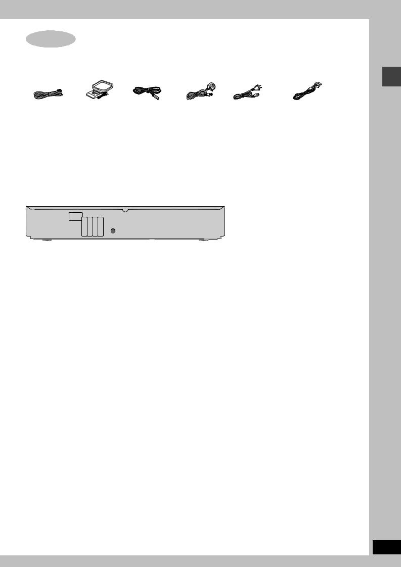
Accessories
Please check and identify the supplied accessories.
∏1 Remote control
(EUR7722X60)
∏2 Remote control batteries
∏1 Video cable
∏1 AC mains lead
[Saudi[Arabia]and[Kuwait]
\Australia\and\N.Z.]
[Russia,[Southeast[Asia,[
[the[Middle[East,[South[Africa,[
[Saudi[Arabia[and[Kuwait]
∏ 1 AM loop antenna
∏1 FM indoor antenna
∏1 System cable
∏1 Speaker cable
4-m cable
∏1 Sheet of speaker-cable stickers
∏4 Large washer screws
∏8 Small screws
Caution for AC Mains Lead/Accessories
[Note]
The included AC mains lead is for use with this unit only. Do not use it with other equipment.
RQT7436
3

Front and surround speaker assembly
RQT7436
4
Simple setup |
Make sure you have all the indicated components before starting assembly, setup, and |
||||
|
|||||
STEP1 |
connection. |
|
2 front and |
4 large washer 4 mounting plates |
|
4 bases |
4 pipes |
||||
2 surround |
screws |
||||
|
|
speaker units |
|
||
|
|
|
8 small screws |
||
|
|
|
|
||
Front and surround speaker assembly
[Note]
The front and surround speaker pairs as well as the pipe pairs are different.
–Check the label on the rear of the speaker before attaching the pipe (‹page 6).
–The pipe with the shorter cable is for the front speaker unit.
Preparation
≥To prevent damage or scratches, lay down a soft cloth and perform assembly on it.
≥For assembly, use a Phillips-head screwdriver.
2 Attach plate A to the speaker.
Ensure that plate A is fastened on straight by lightly tightening the top and bottom screws alternately until fully tightened.
Small screws
Speaker
Plate A
Polyfoam
1 Attach the pipe to the base.
1 Thread the speaker cable through the base.
Lessen excess speaker cable.
|
Thread the |
|
Cable |
speaker cable |
|
through here. |
||
|
||
|
Hole for screw |
Groove
2 Insert the pipe.
Insert the pipe while gently pulling on the speaker cable.
3 Secure the pipe to the
base. |
Rear side of base |
|
|
||
Ensure the screw is |
Large |
|
securely fastened. |
washer |
|
screw |
||
|
||
|
Cable |
The supplied stands are specially designed for attachment to Panasonic SB-PF921 front speakers and SB-PS921 surround speakers. Only use as indicated in this setup.
2 Attach the stands to the front and surround speakers.
≥There is no difference between the right and left speakers and stands. ≥Using the polyfoam included with this unit may be convenient.
1Remove the screw and separate the mounting plate into two parts.
Plate B Plate A
Small screw
You can also attach to the upper rear of the speaker.
The height of the speaker is indicated in the diagram
(‹ page 5) when attaching plate A to the upper rear or lower rear of the speaker.
3 Place the pipe on plate A and attach plate B.
Plate B |
Rotate the pipe so that the flat |
|
side is facing away from the |
|
back of the speaker. |
Fit the offset into the slot and slide plate B into the locked position.
Plate B
Offset


 Slot
Slot
4Secure the plate with the same screw removed in procedure 1.
Small screw

∫ Front and surround speaker height
(Assembled diagram)
Speaker |
You can adjust within this range. |
||
1,160 mm 750 mm |
|
|
704 mm |
|
|
|
|
Pipe |
|
|
|
|
818 mm |
575 mm |
Stopper |
Base |
screw |
||
|
|
Do not |
|
|
|
|
|
Attach to lower |
|
Attach to upper |
remove. |
|
|
||
rear of speaker. |
|
rear of speaker. |
|
3 Adjust the speaker height.
≥Check the screws you tightened on page 4.
e.g. Attaching the stand to the lower rear of the speaker
1Loosen the attached speaker mounting plate screw until the attached speaker is slightly loose and adjustable.
Be careful not to loosen the screw too much or the speaker may detach and fall.
2 With one hand on the base and the other holding the speaker, adjust the height of the speaker up and down.
≥After adjusting the height, tighten the screw on the mounting plate securely.
Phillips-head screwdriver
Stopper screw
Screw to stop mounting plate from moving or sliding below this point.
For your reference
You can enjoy good acoustics by adjusting the height of the speaker to the height of the television so the center positions of both are approximately the same.
4 Connect the speaker cables.
1 Twist off the vinyl ends of |
Rear speaker panel |
the speaker cables. |
Insert the wire fully.
_: Copper
`: Silver
Push!
2 Press the speaker cable into the groove.
If there is any excess speaker cable, 
 detach the rubber cap on the top of
the pipe and thread the speaker cable into the opening while pulling
the speaker cable from the bottom of the base.
5 Fasten the speaker cable to the base.
1 Press the speaker |
2 Fit the speaker |
cable and thread |
cable into the |
between the |
base cover |
hooks. |
groove as far as |
|
possible. |
Rear side of base |
Cable |
|
∫ Preventing the speakers from falling over (Front and surround speakers)
Preparation |
|
|
Attach screw eyes (not included) to secure the speakers to the wall |
|
Screw eye (not included) Wall |
(‹right diagram ). |
e.g. |
String (not included) |
≥You will need to obtain the appropriate screw eyes to match the |
|
|
walls and pillars to which the screw eyes are going to be |
|
|
fastened. |
|
|
≥Consult with a qualified housing contractor concerning the |
|
|
appropriate procedure when attaching to a concrete wall or a |
|
|
surface that may not have strong enough support. Improper |
|
Approx. 150 mm |
attachment may result in damage to the wall or speakers. |
|
|
|
|
|
1 Thread the string (not included) through the slot on the |
|
Rear of the speaker |
rear of the speaker to prevent it from falling over. |
|
|
2 Loop the string through the screw eye and tie tightly. |
|
|
Front and surround speaker assembly
RQT7436
5

Locating
RQT7436
6
STEP2 |
|
How you set up your speakers can affect the bass and the sound field. Note the following points. |
Locating |
≥Place speakers on flat secure bases. |
|
walls and windows with thick curtains. |
||
|
|
≥Placing speakers too close to floors, walls, and corners can result in excessive bass. Cover |
Do not use a front speaker as a surround speaker or vice versa. Verify the type of speaker with the label on the rear of the speaker.
FRONT (L, R) SURROUND (L, R) |
CENTER |
SUBWOOFER |
 Speaker labels
≥The left and right speaker pairs are the same with respect to the front and surround speakers.
Setup example
Main unit
≥Place the front, center, and surround speakers at approximately the same distance from the seating position. The angles in the diagrams are approximate.
≥Use only supplied speakers
Using other speakers can damage the unit and sound quality will be negatively affected.
≥Set the speakers up on an even surface to prevent them from falling. Take proper precautions to prevent the speakers from falling if you cannot set them up on an even surface.
Main unit
[Note]
Keep your speakers at least 10 mm away from the system for proper ventilation.
Center speaker
≥Vibration caused by the center speaker can disrupt the picture if it is placed directly on the television. Put the center speaker on a rack or shelf.
≥To prevent the speakers from falling, do not place directly on top of the television.
Subwoofer
Place to the right or left of the television, on the floor or a sturdy shelf so that it won’t cause vibration. Leave 10 cm at the rear for ventilation.
Caution
Hold the speakers by the sides. Applying pressure to the front net can damage the speaker.
Notes on speaker use
≥You can damage your speakers and shorten their useful life if you play sound at high levels over extended periods.
≥Reduce the volume in the following cases to avoid damage.
–When playing distorted sound.
–When the speakers are receiving howling from a record player, noise from FM broadcasts, or continuous signals from an oscillator, test disc, or electronic instrument.
–When adjusting the sound quality.
–When turning the unit on or off.
If irregular coloring occurs on your television
The supplied speakers are designed to be used close to a television, but the picture may be affected with some televisions and setup combinations.
If this occurs, turn the television off for about 30 minutes.
The television’s demagnetizing function should correct the problem. If it persists, move the speakers farther away from the television.
Caution
≥The main unit and supplied speakers are to be used only as indicated in this setup. Failure to do so may lead to damage to the amplifier and/or the speakers, and may result in the risk of fire. Consult a qualified service person if damage has occurred or if you experience a sudden change in performance.
≥Do not attempt to attach these speakers to walls using methods other than those described in this manual.

STEP3 Connecting speakers with the subwoofer
Attach the speaker-cable stickers to make connection easier.
Speaker cable |
Sheet of speaker-cable stickers |
||
≥4-m cable: For center speaker |
|
|
|
|
|
|
|
Speaker-cable sticker
2 FRONT (R)

 1 FRONT (L)
 4 SURROUND (R)
3 SURROUND (L)
SUBWOOFER
5 CENTER
2 1 4 3 5


 Silver

 Copper
Insert the wire fully.
Click!
\Note]
≥Never short-circuit positive (i) and negative (j) speaker wires.
≥Be sure to connect only positive (copper) wires to positive (i) terminals and negative (silver) wires to negative (j) terminals. Incorrect connection can damage the speakers.
Connecting speakers with the subwoofer
RQT7436
7

Video connections
RQT7436
8
STEP4 Video connections
≥Do not connect through the video cassette recorder.
Due to copy guard protection, the picture may not be displayed properly.
≥Turn the television off before connecting, and refer to the television’s operating instructions.
∫ Television with a VIDEO IN terminal
Television
(not included) VIDEO IN
Video cable
(included)
Back of the |
COMPONENT |
main unit |
VIDEO OUT |
PB (480P/480I) Y |
S-VIDEO
OUT
PR
VIDEO
OUT
∫ Television with an S-VIDEO IN terminal
Television |
S-VIDEO |
(not included) |
IN |
|
|
S-video cable |
|
|
(not included) |
Back of the |
COMPONENT |
|
PB |
VIDEO OUT |
|
main unit |
(480P/480I) Y |
|
|
S-VIDEO |
|
|
|
|
|
|
OUT |
|
PR |
VIDEO |
|
|
|
|
|
OUT |
Video cable
∫Television with COMPONENT VIDEO IN terminals
Television |
COMPONENT |
|
|
(not included) |
|
||
|
VIDEO IN |
|
|
|
|
PR PB Y |
Video cables |
|
|
|
|
|
|
|
(not included) |
Back of the |
COMPONENT |
|
|
main unit |
|
VIDEO OUT |
|
PB (480P/480I) Y |
|
||
|
PR |
VIDEO |
|
|
|
|
|
|
|
OUT |
|
\Russia]
∫ Television with SCART terminal
AV
Television
(not included)
Scart cable 
(not included)
Back of the main unit
AV
S-VIDEO OUT terminal
The S-VIDEO OUT terminal achieves a more vivid picture than the VIDEO OUT terminal by separating the chrominance (C) and luminance (Y) signals. (Actual results depend on the television.)
COMPONENT VIDEO OUT terminals
These terminals can be used for either interlace or progressive output and provide a purer picture than the S-VIDEO OUT terminal. Connection using these terminals outputs the color difference signals (PB/PR) and luminance signal (Y) separately in order to achieve high fidelity in reproducing colors.
≥The description of the component video input terminals depends on the television or monitor (e.g. Y/PB/PR, Y/B-Y/R-Y, Y/CB/CR). Connect to terminals of the same color.
≥\Russia] When making this connection, select “Video/Y PB PR” or “S-Video/Y PB PR” from QUICK SETUP (‹ page 10).
SCART (AV) terminal
To improve picture quality, you can change the video signal output from the SCART (AV) terminal from “Video” to either “S-Video” or “RGB” to suit the type of television you are using. Select “S-Video/ Y PB PR” or “RGB/No Output” from QUICK SETUP (‹ page 10).
To enjoy progressive video
≥Connect to the component video input terminals on a 480P compatible television. (Video will not be displayed correctly if connected to an incompatible television.)
≥When playing NTSC discs, change video output mode to “480P” (‹ page 19) or press [PROGRESSIVE] on the main unit so “PROG.” appears on the display.
All Panasonic televisions that have 480P input connectors are compatible. Consult the manufacturer if you have another brand of television.
[Note]
Output from this unit is interlace if you have connected to the television through the VIDEO OUT, S-VIDEO OUT or SCART (AV) terminal or when playing PAL discs, even if “PROG.” is on the display.
STEP5 Radio and system connection
System cable |
AM loop |
FM indoor |
AC mains lead |
|
antenna |
antenna |
[Saudi[Arabia]and[Kuwait] [Australia\and\N.Z.] [Russia,[Southeast]Asia,[the[Middle[East,[ |
|
|
|
[South[Africa,[Saudi[Arabia[and[Kuwait] |
|
|
|
|
≥Connect the AC mains lead after all other connections are complete. |
|
|
|
|
|
|
|
|
|
||
≥Optional antenna connections (‹ page 23). |
|
\Southeast\Asia,\the\Middle\East,\ |
|||||||||
|
|
||||||||||
FM indoor antenna |
|
\South\Africa,\Saudi\Arabia\and\Kuwait[ |
|||||||||
|
Before connecting the |
||||||||||
|
AM loop antenna |
||||||||||
Adhesive tape |
AC mains lead |
||||||||||
Stand the antenna up on its base. Place |
|||||||||||
Affix this end of the antenna |
Set the voltage. |
||||||||||
the antenna where reception is best. |
|||||||||||
where reception is best. |
|||||||||||
Keep loose antenna cable away from |
|
|
|
|
|
|
|
|
|
||
|
|
|
127 V |
|
110 V |
|
220 V-230 V |
|
240 V |
||
|
other wires and cables. |
|
|
|
|
|
|||||
|
|
|
|
|
|
|
|
|
|
||
|
|
|
|
|
|
|
Click! |
Subwoofer |
VOLT ADJ |
|
|
|
|
|
|
|
|
|
|
||
|
|
|
|
|
|
|
|
|
|
Use a flat-head screwdriver to turn |
|
|
|
|
|
|
|
|
|
|
the voltage selector on the back of |
Main unit |
|
|
|
|
|
|
|
|
the subwoofer to the appropriate |
|
|
|
|
|
|
|
|
|
position for the area in which this |
||
|
|
|
|
|
|
|
|
|
|
|
|
|
|
|
|
|
|
|
|
|
system is used. |
|
(75h) |
IN |
VCR |
TV |
LINE |
COMPONENT VIDEO OUT |
|
If the power supply in your area is |
||
|
FM ANT |
OPTICAL |
|
|
|
|
|
|
|
|
|
|
|
AUX AUDIO AUDIO |
OUT |
|
(480P/480I) |
|
|
115 V or 120 V, please set the voltage |
|
|
|
|
IN |
IN |
PB |
Y |
|
|||
|
|
|
|
|
|
|||||
|
AM ANT |
|
L |
|
|
|
|
S-VIDEO |
|
|
A |
EXT |
|
R |
|
|
|
|
OUT |
|
selector as follows: |
LOOP |
|
|
|
|
|
|
|
|
||
|
|
|
|
|
|
|
|
1 |
≥For 115 V: Set to 110 V. |
|
|
|
|
|
|
|
PR |
OUT |
|
||
|
|
|
|
|
|
|
VIDEO |
|
|
|
|
|
|
|
|
|
|
|
|
|
≥For 120 V: Set to 127 V. |
|
Catch up |
|
|
|
|
|
|
|
||
|
|
|
|
|
|
|
|
|
2 |
AC mains lead |
|
To disconnect |
|
|
|
|
|
|
|||
Press the catch
|
and pull out. |
|
|
|
|
|
|
|
To disconnect |
To household mains socket |
|||
|
|
|
|
|||
|
|
|
|
|||
|
|
|
|
Press the catch |
||
|
|
|
|
|
||
|
|
System cable |
|
and pull out. |
Catch up |
|
|
|
|
|
|
|
|
Conserving power |
|
|
||||
|
[Saudi[Arabia]and[Kuwait] |
|||||
The main unit consumes a small amount of power, even when it is turned |
|
BE SURE TO READ THE CAUTION FOR THE AC |
||||
off (For Russia, Australia and N.Z.: approx. 0.7 W or for Southeast Asia, |
|
MAINS LEAD ON PAGE 3 BEFORE CONNECTION. |
||||
the Middle East, South Africa, Saudi Arabia and Kuwait: approx. 0.9 W). |
|
|
|
|||
|
|
|
||||
To save power when the unit is not to be used for a long time, unplug it |
|
|
|
|||
from the household mains socket. |
|
|
|
|||
You will need to reset some memory items after plugging in the unit. |
|
|
|
|||
STEP6 The remote control
Remote control |
Batteries |
2Insert so the poles (i and j) match those in the remote control.
3
R6/LR6, AA, UM-3 |
1 ≥Do not use |
rechargeable type |
|
|
batteries. |
Do not:
≥mix old and new batteries.
≥use different types at the same time. ≥heat or expose to flame.
≥take apart or short circuit.
≥attempt to recharge alkaline or manganese batteries. ≥use batteries if the covering has been peeled off.
Mishandling of batteries can cause electrolyte leakage which can damage items the fluid contacts and may cause a fire.
Remove if the remote control is not going to be used for a long period of time. Store in a cool, dark place.
∫ Use
Aim at the sensor (‹ page 10), avoiding obstacles, at a maximum range of 7 m directly in front of the unit.
Radio and system connection/The remote control
RQT7436
9

QUICK SETUP/Control reference guide
RQT7436
10
STEP7 QUICK SETUP
The QUICK SETUP screen assists you to make necessary settings.
Turn on the television and select the appropriate video input on the television.
1 |
2 |
3 |
|
|
4 |
5 |
6 |
|
|
|
DVD/CD |
|
|
SETUP |
Select |
|
|
|
|
|
SHIFT |
|
|
|
|
|
SETUP |
||
|
r |
MUTING |
RETURN |
|
SHIFT |
|
|||
|
|
|
|
ENTER |
ENTER |
r |
MUTING |
||
|
|
|
|
Register |
|
|
|||
|
|
|
|
|
|
|
|
||
Turn the unit |
Select |
Shows QUICK |
Follow the messages |
Press to |
Press to exit. |
||||
on. |
“DVD/CD”. |
SETUP screen. |
and make the settings. |
finish QUICK |
|
|
|
||
|
|
|
|
|
|
SETUP. |
|
|
|
To change these settings later |
|
|
|
|
|
|
|
|
|
Select “QUICK SETUP” in “Others” tab (‹ page 21). |
|
|
|
|
|
|
|||
Control reference guide |
|
Standby/on indicator |
|
|
|
||||
See reference pages in brackets. |
|
|
When the unit is connected to the AC mains |
|
|
||||
|
|
supply, this indicator lights up in standby mode and |
|
||||||
|
|
|
|
|
|
||||
goes out when the unit is turned on.
Turn the unit on/off.
Switch the television’s video input mode (29).
(12, 13)
(12)
(13, 16, 17)
(10)
(18, 29)
|
AV SYSTEM |
|
(29) |
Source select button [INPUT SELECTOR] (22) |
|
|
|
TV |
VCR |
||
|
|
DVD/CD#FM#AM#TV#VCR#AUX# |
|||
|
|
|
|
||
|
|
|
|
Select the source |
|
TV/AV |
AUX |
TUNER/BAND DVD/CD |
D-IN (Digital In)#Return to DVD/CD |
||
|
DIGITAL |
|
|
DIGITAL, AUX (29) |
|
|
|
|
|
|
|
|
|
|
|
TUNER/BAND (22) |
|
DISC 1 |
DISC 2 |
DISC 3 |
DVD/CD (10) |
Digital in button [DIGITAL IN] (29) |
1 |
2 |
3 |
|
|
|
|
|||
DISC 4 |
DISC 5 |
CH |
|
VOLUME |
|
|
|
|
OPEN/CLOSE |
4 |
5 |
6 |
(22, 29) |
|
|
|
|
|
|
|
|
|
|
|
DISC EXCHANGE |
|
|
|
|
INPUT |
1 |
2 |
3 |
4 |
5 |
|
|
|
|
|
DISC SKIP |
|
|
|
/I |
SELECTOR |
|
|
|
|
V.R.S M.R.S |
DIGITAL IN C.S.M PROGRESSIVE CD MODE |
FM MODE |
MEMORY |
DOWN |
UP |
|
7 |
8 |
9 |
VOLUME |
|
|
|
|
|
5 |
DISC SELECTOR |
TUNE MODE |
TUNING |
|
||
|
|
|
|
|
|
|
|
|
|
|
|
PHONES |
|||
|
-/-- |
S10 |
Adjust the volume. |
V.R.S, M.R.S indicators (25) |
Remote control signal |
CANCEL |
0 |
|
|||
SKIP |
|
SLOW/SEARCH |
|
|
sensor |
|
|
|
|
RDS ([Russia[), Progressive button (23, 12) |
|
TOP MENU |
|
MENU |
|
Standby/on switch [Í/I] |
|
|
|
Press to switch the unit from on to standby mode or vice versa. |
|||
|
|
|
(13, 16, 17) |
||
|
|
|
In standby mode, the unit is still consuming a small amount of |
||
DIRECT |
|
PLAY |
|
||
|
|
power. |
|
||
NAVIGATOR |
|
LIST |
|
|
|
|
|
|
|
|
|
|
ENTER |
|
|
|
|
DISPLAY |
|
RETURN |
(13, 29) |
|
|
|
|
|
|
|
|
TV VOL |
|
|
TV VOL |
|
|
|
|
SUBWOOFER |
SFC |
C.FOCUS |
MIX 2CH |
|
|
|
|
LEVEL |
SUPER SRND |
PL |
SUBWOOFER |
SFC |
C.FOCUS |
MIX 2CH |
|
|
|
|
|
||||
|
|
|
|
LEVEL |
SUPER SRND |
PL |
|
SLEEP |
POSITION |
ZOOM |
SETUP |
(26) |
(24) |
(24) |
(24, 26) |
C.S.M |
MEMORY |
AUDIO |
MUTING |
||||
|
PAGE |
AV EFFECT |
REPEAT |
SLEEP |
POSITION |
ZOOM |
SETUP |
FL DISPLAY |
C.S.M |
MEMORY |
AUDIO |
MUTING |
|||
GROUP |
CD MODE |
PLAY MODE |
(26, 27) |
(14) |
(14) |
(20, 27) |
|
|
|
|
|
||||
SHIFT |
TEST |
|
|
|
|
|
|
CH SELECT QUICK REPLAY SUBTITLE |
|
PAGE |
AV EFFECT |
REPEAT |
|||
|
|
|
|
FL DISPLAY |
GROUP |
CD MODE |
PLAY MODE |
|
|
|
|
(13) |
(12, 14) |
(13, 25) |
(15) |
TEST
CH SELECT QUICK REPLAY SUBTITLE
(25) (14) (14)
To use functions labeled in orange:
AC supply
indicator (AC IN) 

This indicator lights when the unit is
connected to the AC mains supply.
While pressing [SHIFT], press the corresponding button.
Discs that can be played
|
|
|
|
|
|
|
|
|
|
|
|
|
Indication |
|
|
|
|
Disc |
|
|
|
|
|
Logo |
used in |
|
Remarks |
||||||||
|
|
|
|
|
operating |
|
|||||||||||
|
|
|
|
|
|
|
|
|
|
|
|
|
|
|
|
|
|
|
|
|
|
|
|
|
|
|
|
|
|
|
instructions |
|
|
|
|
|
|
|
|
|
|
|
|
|
|
|
|
|
|
|
|
|
|
|
|
|
|
|
|
|
|
|
|
|
|
|
|
Recorded using Version 1.1 of the |
≥Recorded with DVD-Video recorders, DVD- |
||
|
|
|
|
|
|
|
|
|
|
|
|
|
|
Video Recording Format (a unified |
Video cameras, personal computers, etc. |
||
|
|
|
|
|
|
|
|
|
|
|
|
|
[RAM] |
video recording standard). |
≥Remove TYPE 2 |
||
|
|
|
|
|
|
|
|
|
|
|
|
|
|
and 4 discs from |
|||
|
|
|
|
|
|
|
|
|
|
|
|
|
|
|
|||
DVD-RAM |
|
|
|
|
|
|
|
|
|
|
|
|
|
|
their cartridges |
|
|
|
|
|
|
|
|
|
|
|
|
|
|
|
|
|
|||
|
|
|
|
|
|
|
|
|
|
|
|
|
|
before use. |
|||
|
|
|
|
|
|
|
|
|
|
|
|
|
|
|
|||
|
|
|
|
|
|
|
|
|
|
|
|
|
|
|
|
|
|
|
|
|
|
|
|
|
|
|
|
|
|
|
|
Recorded using the DCF (Design |
≥Recorded with Panasonic DVD-Video |
||
|
|
|
|
|
|
|
|
|
|
|
|
|
[JPEG] |
rule for Camera File system) |
recorders. |
||
|
|
|
|
|
|
|
|
|
|
|
|
|
standard. |
≥To play JPEG files, select “Play as Data Disc” |
|||
|
|
|
|
|
|
|
|
|
|
|
|
|
|
||||
|
|
|
|
|
|
|
|
|
|
|
|
|
|
|
in Other Menu (‹ page 19). |
||
|
|
|
|
|
|
|
|
|
|
|
|
|
|
|
|
|
|
|
|
|
|
|
|
|
|
|
|
|
|
|
[DVD-A] |
— |
|
|
|
DVD-Audio |
|
|
|
|
|
|
|
|
|
|
|
|
|
|
|
|
|
|
|
|
|
|
|
|
|
|
|
|
|
[DVD-V] |
Some DVD-Audio discs contain DVD-Video content. |
||||
|
|
|
|
|
|
|
|
|
|
|
|
|
To play DVD-Video content, select “Play as DVD-Video” in Other Menu (‹ page 19) |
||||
|
|
|
|
|
|
|
|
|
|
|
|
|
|
||||
|
|
|
|
|
|
|
|
|
|
|
|
|
|
||||
|
|
|
|
|
|
|
|
|
|
|
|
|
|
|
|
|
|
|
|
|
|
|
|
|
|
|
|
|
|
|
|
— |
|
|
|
DVD-Video |
|
|
|
|
|
|
|
|
|
|
|
|
|
|
|
|
|
|
|
|
|
|
|
|
|
|
|
|
|
|
[DVD-V] |
|
|
|
|
|
|
|
|
|
|
|
|
|
|
|
|
|
|
|
|
|
|
|
|
|
|
|
|
|
|
|
|
|
|
|
|
|
|
|
|
|
|
|
|
|
|
|
|
|
|
|
|
|
Panasonic DVD-R recorded and finalized§ on Panasonic DVD-Video recorders or |
||||
DVD-R |
|
|
|
|
|
|
|
|
|
|
|
|
|
DVD-Video cameras are played as DVD-Video on this unit. |
|||
|
|
|
|
|
|
|
|
|
|
|
|
|
|
|
|
|
|
|
|
|
|
|
|
|
|
|
|
|
|
|
|
|
|
|
|
|
|
|
|
|
|
|
|
|
|
|
|
|
|
— |
|
|
|
Video CD |
|
|
|
|
|
|
|
|
|
|
|
|
|
|
|
|
|
|
|
|
|
|
|
|
|
|
|
|
|
|
[VCD] |
|
|
|
|
|
|
|
|
|
|
|
|
|
|
|
|
|
|
|
|
|
|
|
|
|
|
|
|
|
|
|
|
|
|
|
|
|
|
|
|
|
|
|
|
|
|
|
|
|
|
|
|
|
Conforming to IEC62107 |
|
|
|
|
|
|
|
|
|
|
|
|
|
|
|
|
|
|
|
|
|
|
SVCD |
|
|
|
|
|
|
|
|
|
|
|
|
|
|
|
|
|
|
|
|
|
|
|
|
|
|
|
|
|
|
|
|
|
|
|
|
|
|
|
|
|
|
|
|
|
|
|
|
|
|
|
|
|
|
|
|
|
|
|
|
|
|
|
|
|
|
|
|
|
|
|
|
|
|
|
|
|
|
|
|
|
|
|
|
|
This unit is compatible with HDCD, but does not support the Peak Extend function. |
|||
|
|
|
|
|
|
|
|
|
|
|
|
|
|
(A function which expands the dynamic range of high level signals) |
|||
CD |
|
|
|
|
|
|
|
|
|
|
|
|
[CD] |
HDCD-encoded CDs sound better because they are encoded with 20 bits, as |
|||
|
|
|
|
|
|
|
|
|
|
|
|
|
|
compared with 16 bits for all other CDs. |
|||
|
|
|
|
|
|
|
|
|
|
|
|
|
|
||||
|
|
|
|
|
|
|
|
|
|
|
|
|
|
≥During HDCD play, “HDCD” lights on the unit’s display. |
|||
|
|
|
|
|
|
|
|
|
|
|
|
|
|
|
|
|
|
|
|
|
|
|
|
|
|
|
|
|
|
|
[WMA] |
≥This unit can play CD-R/RW (audio recording disc) recorded with the formats on |
|||
|
|
|
|
|
|
|
|
|
|
|
|
|
the left. Close the sessions or finalize§ the disc after recording. |
||||
|
|
|
|
|
|
|
|
|
|
|
|
|
[MP3] |
||||
CD-R |
|
|
|
|
|
|
|
|
|
|
|
|
≥HighMAT discs |
|
|
|
|
|
|
|
|
|
|
— |
[JPEG] |
|
|
|
|||||||
CD-RW |
|
|
|
|
|
|
WMA, MP3 or JPEG files only. |
|
|
|
|||||||
|
|
|
|
|
|
|
|
|
|
|
|
[CD] |
|
|
|
||
|
|
|
|
|
|
|
|
|
|
|
|
|
To play without using the HighMAT function, select “Play as Data Disc” in Other |
||||
|
|
|
|
|
|
|
|
|
|
|
|
|
[VCD] |
||||
|
|
|
|
|
|
|
|
|
|
|
|
|
Menu (‹ page 19). |
|
|
|
|
|
|
|
|
|
|
|
|
|
|
|
|
|
|
|
|
|
|
|
|
|
|
|
|
|
|
|
|
|
|
|
|
|
|
|
|
§A process that allows play on compatible equipment.
≥It may not be possible to play the above discs in all cases due to the type of disc or condition of the recording.
∫ Discs that cannot be played |
∫ Video systems |
DVD-ROM, CD-ROM, CDV, CD-G, DVD+R, iRW, DVD-RW, SACD, |
– This unit can play PAL and NTSC, but your television must match |
Divx Video Discs and Photo CD, DVD-RAM that cannot be removed |
the system used on the disc. |
from their cartridge, 2.6-GB and 5.2-GB DVD-RAM, and “Chaoji |
– PAL discs cannot be correctly viewed on an NTSC television. |
VCD” available on the market including CVD, DVCD and SVCD that |
– This unit can convert NTSC signals to PAL 60 for viewing on a PAL |
do not conform to IEC62107. |
television (‹ page 20, “NTSC Disc Output” in “Video” tab). |
Discs that can be played/Main unit and disc caution
∫ Audio format of DVDs
This unit automatically recognizes and decodes discs with these symbols.
Main unit and disc caution
∫ To prevent damage
Do not:
–load more than one disc per tray.
–touch the drawer or the carousel while they are in motion. –rotate the carousel by hand.
–close the drawer by hand.
∫ To clean discs
[DVD-A] [DVD-V] [VCD] [CD]
Wipe with a damp cloth and then wipe dry.
[RAM] [DVD-R]
≥Clean with an optional DVD-RAM/PD disc cleaner (LF-K200DCA1, where available).
≥Never use cloths or cleaners for CDs, etc.
∫ Disc handling precautions
≥Do not attach labels or stickers to discs (This may cause disc warping, rendering it unusable).
≥Do not write on the label side with a ball-point pen or other writing instrument.
≥Do not use record cleaning sprays, benzine, thinner, static electricity prevention liquids or any other solvent.
≥Do not use scratch-proof protectors or covers. ≥Do not use the following discs:
–Discs with exposed adhesive from removed stickers or labels (rented discs, etc.).
–Discs that are badly warped or cracked.
–Irregularly shaped discs, such as heart shapes.
RQT7436
11
 Loading...