


CD Stereo System
Operating Instructions
Model No. SC-PM10
Before connecting, operating or adjusting this product, please read these instructions completely.
Please keep this manual for future reference.
|
|
|
|
|
|
PC |
RQT6675-1P |
||
|
||||
|
||||
Dear customer
Thank you for purchasing this product.
For optimum performance and safety, please read these instructions carefully.
These operating instructions are applicable to the following system.
|
System |
SC-PM10 |
|
use |
|
|
|
Main unit |
SA-PM10 |
||
|
|||
Before |
|
|
|
Speakers |
SB-PM10 |
||
|
|||
|
|
|
The model number and serial number of this product can be found on either the back or the bottom of the unit.
Please note them in the space provided below and keep for future reference.
MODEL NUMBER
SERIAL NUMBER
User memo:
DATE OF PURCHASE
DEALER NAME
DEALER ADDRESS
TELEPHONE NUMBER
WARNING:
TO REDUCE THE RISK OF FIRE, ELECTRIC SHOCK OR PRODUCT DAMAGE, DO NOT EXPOSE THIS APPARATUS TO RAIN, MOISTURE, DRIPPING OR SPLASHING AND THAT NO OBJECTS FILLED WITH LIQUIDS, SUCH AS VASES, SHALL BE PLACED ON THE APPARATUS.
CAUTION:
TO PREVENT ELECTRIC SHOCK MATCH WIDE BLADE OF PLUG TO WIDE SLOT, FULLY INSERT.
Inside of product
2 |
Table of contents |
|
Before use |
|
Supplied accessories ................................................. |
3 |
IMPORTANT SAFETY INSTRUCTIONS ..................... |
4 |
Listening caution ........................................................ |
5 |
Placement of speakers ............................................... |
5 |
The remote control ..................................................... |
5 |
Connections ................................................................ |
6 |
Front panel controls ................................................... |
8 |
Setting the time ........................................................... |
9 |
Convenient Functions ................................................ |
9 |
Turning the demo function off ................................... |
9 |
Listening operations |
|
The radio: manual tuning ........................................... |
10 |
The radio: preset tuning ............................................. |
11 |
CDs ............................................................................... |
12 |
Cassette tapes ............................................................. |
15 |
Recording operations |
|
Before recording ......................................................... |
16 |
Recording from the radio ........................................... |
16 |
Recording CDs ............................................................ |
17 |
Timers and others |
|
Sound Quality .............................................................. |
19 |
Using the timers .......................................................... |
20 |
Reference |
|
Troubleshooting guide ............................................... |
22 |
Warranty ...................................................................... |
23 |
Specifications ................................................. |
Back cover |
Maintenance ................................................... |
Back cover |
Product Service .............................................. |
Back cover |
CAUTION!
THIS PRODUCT UTILIZES A LASER.
USE OF CONTROLS OR ADJUSTMENTS OR PERFORMANCE OF PROCEDURES OTHER THAN THOSE SPECIFIED HEREIN MAY RESULT IN HAZARDOUS RADIATION EXPOSURE.
DO NOT OPEN COVERS AND DO NOT REPAIR YOURSELF. REFER SERVICING TO QUALIFIED PERSONNEL.
CAUTION!
DO NOT INSTALL OR PLACE THIS UNIT IN A BOOKCASE, BUILT-IN CABINET OR IN ANOTHER CONFINED SPACE. ENSURE THE UNIT IS WELL VENTILATED. TO PREVENT RISK OF ELECTRIC SHOCK OR FIRE HAZARD DUE TO OVERHEATING, ENSURE THAT CURTAINS AND ANY OTHER MATERIALS DO NOT OBSTRUCT THE VENTILATION VENTS.
RQT6675

Supplied accessories
Please check and identify the supplied accessories.
Use numbers indicated in parentheses when asking for replacement parts.
AC power supply cord ...................................... |
1 pc. |
(K2CB2CB00006) |
|
FM indoor antenna ............................................ |
1 pc. |
(RSA0006-L) |
|
AM loop antenna ............................................... |
1 pc. |
(RSA0033-1) |
|
Remote control transmitter .............................. |
1 pc. |
(EUR7711010) |
|
Remote control batteries ................................ |
2 pcs. |
CAUTION: TO REDUCE THE RISK OF ELECTRIC SHOCK, DO NOT REMOVE SCREWS. NO USER-SERVICEABLE PARTS INSIDE.
REFER SERVICING TO QUALIFIED
SERVICE PERSONNEL.
The lightning flash with arrowhead symbol, within an equilateral triangle, is intended to alert the user to the presence of uninsulated  dangerous voltage
 within the product
 s enclosure that may be of sufficient magnitude to constitute a risk of electric shock to persons.
The exclamation point within an equilateral triangle is intended to alert the user to the presence of important operating and maintenance (servicing) instructions in the literature accompanying the appliance.
Before use
3 |
RQT6675 |
IMPORTANT SAFETY INSTRUCTIONS
Before use
Read these operating instructions carefully before using the unit. Follow the safety instructions on the unit and the safety precautions listed below. Keep these operating instructions handy for future reference.
Safety
1.Power source—Connect the unit to a power source of the type described in these instructions or as marked on the unit.
2.Polarization—The unit is equipped with a polarized power plug where one blade is wider than the other. This safety feature ensures that the plug fits into your household AC outlet only one way. If the plug doesn’t fit one way, try reversing it. If the plug still doesn’t fit, contact an electrician to replace the obsolete outlet. Do not attempt to defeat the safety purpose of the plug.
3.Power cord protection—Route the AC power supply cord so that it will not be walked on or pinched by items placed on or against it. Never take hold of the plug or cord with wet hands. Always grasp the plug body firmly when connecting and disconnecting it.
4.Overloading—When connecting the AC power supply cord, be careful not to overload the household AC outlet, extension cord, or outlet from any other device as this can result in fire or electric shock.
5.Nonuse periods—Turn the unit off when it is not in use. Unplug the unit from the household AC outlet if it is not to be used for a long time. Unplug the unit during lightning storms.
6.Attachments and accessories—Use only the attachments and accessories recommended in these operating instructions.
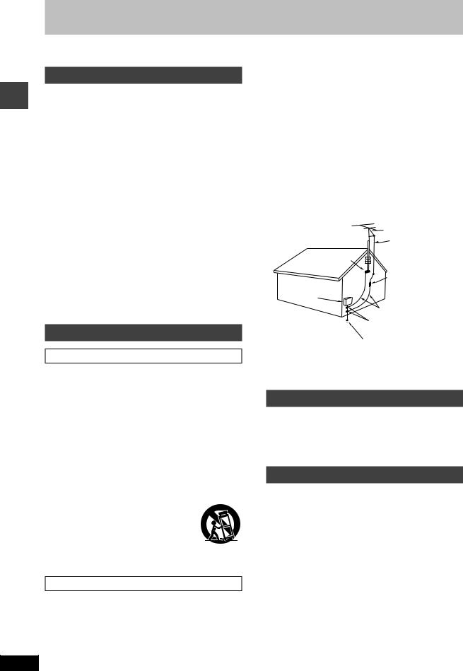
3.Power lines—Take care when setting up an outdoor antenna that it is not near overhead power lines, electric lights, or electrical circuits, and that there is no danger of the antenna falling on power lines, electric lights, or electrical circuits. When installing an outdoor antenna, take extreme care not to touch such power lines or circuits, as contact with them can be fatal.
4.Outdoor antenna grounding—If you connect an outdoor antenna, ground the antenna system to protect against voltage surges and built-up static charges. Section 810 of the National Electrical Code, ANSI/NFPA No. 70-1990, provides information about grounding of the mast and supporting structure, grounding of the leadin wire to an antenna discharge unit, size of grounding conductors, location of antenna-discharge unit, connection to grounding electrodes, and requirements for the grounding electrode. Refer to this diagram.
|
|
ANTENNA |
|
|
LEAD IN |
|
GROUND |
WIRE |
|
|
|
|
CLAMP |
|
ELECTRIC |
|
ANTENNA |
|
DISCHARGE UNIT |
|
SERVICE |
|
(NEC SECTION 810-20) |
EQUIPMENT |
|
|
|
|
GROUNDING CONDUCTORS |
|
|
(NEC SECTION 810-21) |
|
|
GROUND CLAMPS |
Installation
Placement
1.Ventilation—Situate the unit so that it receives proper ventilation. Do not install in a confined space such as a bookcase or cabinet. Allow at least 10 cm (4 inches) clearance from the rear of the unit. To prevent the risk of electric shock or fire due to overheating ensure curtains and other materials do not obstruct the unit’s ventilation.
2.Foreign material—Ensure objects and liquids do not get into the unit. Avoid exposing the unit to excessive smoke, dust, mechanical vibration, and shock.
3.Magnetism—Situate the unit away from equipment and devices that generate strong magnetic fields.
4.Stacking—Do not place heavy objects on top of this unit.
5.Surface—Place the unit on a flat, level surface.
6.Carts and stands—Use the unit only with carts and stands recommended by the manufacturer. Move carts with care. Sudden stops, excessive force, and uneven surfaces can cause carts to overturn.
7.Wall and ceiling mounting—Do not mount the unit on walls or ceilings unless specified in the instructions.
Environment
4 |
1.Water and moisture—Do not use the unit near water, such as near a bathtub or swimming pool. Avoid damp basements.
2.Heat—Situate the unit away from heat sources, such as radiators.
Do not situate where temperatures fall below 5˚C (41˚F) or rise above 35˚C (95˚F).
POWER SERVICE GROUNDING ELECTRODE SYSTEM
(NEC ART 250, PART H)
NEC—NATIONAL ELECTRICAL CODE
Maintenance
(See back cover for details.)
Unplug the unit from the household AC outlet before cleaning.
Clean with a damp cloth.
Do not use abrasive pads, scouring powders, or solvents.
Service
1.Damage requiring service—The unit should be serviced by qualified service personnel if:
(a)The AC power supply cord or the plug has been damaged; or
(b)Objects or liquids have gotten into the unit; or
(c)The unit has been exposed to rain; or
(d)The unit does not operate normally or exhibits a marked change in performance; or
(e)The unit has been dropped or the cabinet damaged.
2.Servicing—Do not attempt to service the unit beyond that described in these operating instructions. Refer all other servicing to authorized servicing personnel.
3.Replacement parts—When parts need replacing ensure the servicer uses parts specified by the manufacturer or parts that have the same characteristics as the original parts. Unauthorized substitutes may result in fire, electric shock, or other hazards.
4.Safety check—After repairs or service, ask the servicer to perform safety checks to confirm that the unit is in proper working condition.
RQT6675

Listening caution
EST. 1924
Selecting fine audio equipment such as the unit you’ve just purchased is only the start of your musical enjoyment. Now it’s time to consider how you can maximize the fun and excitement your equipment offers. This manufacturer and the Electronic Industries Association’s Consumer Electronics Group want you to get the most out of your equipment by playing it at a safe level. One that lets the sound come through loud and clear without annoying blaring or distor- tion—and, most importantly, without affecting your sensitive hearing.
We recommend that you avoid prolonged exposure to excessive noise.
Sound can be deceiving. Over time your hearing “comfort level” adapts to higher volumes of sound. So what sounds “normal” can actually be loud and harmful to your hearing.
Guard against this by setting your equipment at a safe level BEFORE your hearing adapts.
To establish a safe level:
•Start your volume control at a low setting.
•Slowly increase the sound until you can hear it comfortably and clearly, and without distortion.
Once you have established a comfortable sound level:
• Set the dial and leave it there.
Taking a minute to do this now will help to prevent hearing damage or loss in the future. After all, we want you listening for a lifetime.
Placement of speakers
Speakers are designed identically so that no left or right channel orientation is necessary.
Notes
•Keep your speakers at least 10 mm (13/32˝) away from the system for proper ventilation.
•These speakers do not have magnetic shielding. Do not place them near televisions, personal computers or other devices easily influenced by magnetism.
•To avoid damage to the speakers, do not touch the speaker cones if you have taken the nets off.
The remote control
Battery installation
R6, AA, UM-3
|
use |
Use of batteries |
Before |
|
•Align the poles (+ and –) properly when inserting the batteries.
•Do not mix old and new batteries or different types of batteries.
•Do not recharge ordinary dry cell batteries.
•Do not heat or disassemble the batteries. Do not allow them to contact flame or water.
•Remove the batteries if the unit is not to be used for a long time.
•Do not keep together with metallic objects such as necklaces.
•Do not use rechargeable type batteries.
•Do not use batteries if the covering has been peeled off.
Mishandling of batteries can cause electrolyte leakage which can damage items the fluid contacts and may cause a fire.
If electrolyte leaks from the batteries, consult your dealer.
Wash thoroughly with water if electrolyte comes in contact with any part of your body.
Correct method of
Remote control signal sensor
Transmission window
About 7 meters in front of the signal sensor.
Operations notes
•Do not place obstacles between the remote control signal sensor and remote control unit.
•Do not expose the remote control signal sensor to direct sunlight or to the bright light of a fluorescent light.
•Take care to keep the remote control signal sensor and end of the remote control unit free from dust.
•If this system is installed in a rack with glass doors, the glass doors’ thickness or color might make it necessary to use the remote control unit a shorter distance from the system.
To prevent damage
•Never place heavy items on top of the unit.
•Do not disassemble or reconstruct the unit.
•Do not spill water or other liquids into the unit.
5 |
RQT6675 |

|
|
|
|
|
|
Connections |
|
|
|
|
|
|
• Plug the AC power supply cord into a household AC outlet |
|
|
|
|
|
|
socket only after all other connections have been made. |
|
|
|
|
|
|
• To prepare the AM loop antenna wire and speaker cords, |
|
|
|
|
|
|
twist the vinyl cover tip and pull off. |
|
|
|
1 |
|
|
|
use |
|
|
2 |
|
|
|
|
|
|
|
|
1 Connect the FM indoor antenna. |
|
Before |
|
|
3 |
4 |
|
|
|
|
|
of interference. |
|||
|
|
|
|
|
Tape the antenna to a wall or column, in a position |
|
|
|
|
|
|
|
where radio signals are received with the least amount |
|
|
|
|
|
|
Note |
|
|
|
|
|
|
For the best reception: |
1 |
|
|
|
|
|
An FM outdoor antenna is recommended. (\ page 7) |
|
Adhesive |
|
|
|
2 Connect the AM loop antenna. |
|
|
|
|
|
|
After attaching the antenna, turn on the system and |
|
|
|
tape |
|
|
|
|
|
|
|
|
|
|
tune in a broadcast station. Put the antenna where the |
|
|
FM indoor |
|
|
|
reception is best and interference is minimal. |
|
|
|
|
|
3 Connect the speaker cables. |
|
|
|
antenna |
|
|
|
|
|
|
|
|
|
|
Connect the speaker cords without tags to the black |
|
|
1 |
2 |
|
|
terminals, so (+) and (–) are correct. |
|
|
|
|
Connect the speaker cords with red tags to the red ter- |
||
|
|
|
|
|
||
|
|
|
|
|
|
|
|
|
|
|
|
|
minals, so (+) and (–) are correct. |
|
|
|
|
|
|
Never allow the exposed wires to contact each other |
|
|
|
|
|
|
when connected. |
|
|
|
|
|
|
Incorrect connection can damage the unit. |
2 |
|
|
|
|
|
Caution |
|
|
|
|
|
Use only the supplied speakers. |
|
|
|
|
|
|
|
|
|
|
|
|
|
|
The combination of the main unit and speakers provide |
|
|
|
|
|
|
the best sound. Using other speakers can damage the |
|
|
1 |
|
|
|
unit and sound quality will be negatively affected. |
|
|
|
|
|
|
|
|
|
|
|
|
|
Caution |
|
|
|
|
|
|
• Use the speakers only with the |
|
|
|
2 |
|
|
recommended system. |
|
|
|
|
|
Failure to do so may lead to damage |
|
|
AM loop antenna |
|
|
|
||
|
|
|
|
to the amplifier and/or the speakers, |
||
|
|
|
|
|
|
|
|
|
|
|
|
|
and may result in the risk of fire. |
|
|
|
|
|
|
Consult a qualified service person if |
|
|
|
|
|
|
damage has occurred or if you |
|
|
|
|
|
|
experience a sudden change in |
|
|
|
|
|
|
performance. |
3 |
|
|
|
|
|
• Do not attach these speakers to walls |
|
(SB-PM10) |
|
|
|
or ceilings. |
|
|
Red ( |
) |
|
|
||
|
|
1 |
|
4 Connect the AC power supply cord. |
||
Black ( |
) |
|
|
|
||
|
|
3 |
2 |
Red tag Copper |
Note |
|
|
|
The included AC power supply cord is for use with this |
||||
|
|
|
||||
|
|
|
|
( |
) |
|
|
|
L |
|
unit only. Do not use it with other equipment. |
||
|
|
|
|
|
||
|
|
R |
|
|
|
|
|
|
|
|
Silver ( |
) |
|
Black ( |
) |
|
Red ( |
) |
|
|
|
|
|
|
|
||
6 |
|
|
|
|
|
|
RQT6675 |
|
|
|
|
|
|
A |
|
|
|
FM outdoor antenna |
|
|
(not included) |
|
|
1 |
|
1 |
2 |
(13/16") |
2 |
|
Shield braid |
|
(19/32") |
Core wire |
|
3 |
|
|
|
|
B |
|
|
|
AM outdoor antenna |
|
|
(not included) |
|
|
5-12 m |
|
|
(16-40ft.) |
|
2 |
|
|
1 |
|
|
Connections
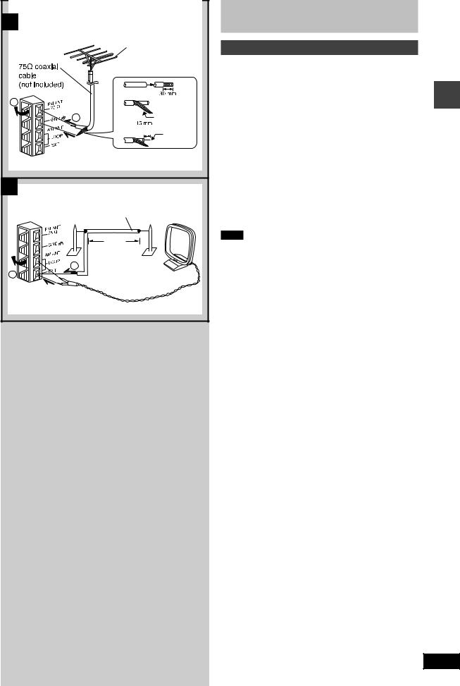
Optional antenna connections
You may need an outdoor antenna if you use this system in a mountainous region or inside a reinforced-concrete building, etc.
A |
FM outdoor antenna |
|
|
|
Disconnect the FM indoor antenna if an FM outdoor |
use |
|||
antenna is installed. |
||||
|
||||
|
|
|
Before |
|
Note |
|
|
||
|
|
|
||
An outdoor antenna should be installed by a qualified |
|
|||
technician only. |
|
|||
|
|
|
||
B |
AM outdoor antenna |
|
|
|
Connect the outdoor antenna without removing the AM loop antenna. Run 5 to 12 m (16-40ft.) of vinyl-covered wire horizontally along a window or other convenient location.
Note
When the unit is not in use, disconnect the outdoor antenna to prevent possible damage that may be caused by lightning. Never use an outdoor antenna during a lightning storm.
7 |
RQT6675 |
Before use
8 |
RQT6675
A |
|
|
|
|
PHONES |
|
|
|
|
|
|
|
1 |
|
|
|
|
|
|
|
|
|
|
|
|
|
|
|
|
Top of the |
|
|
|
|
|
|
|
unit |
|
2 |
|
|
|
|
|
|
|
|
|
|
|
|
OPEN |
3 |
|
|
|
|
|
|
|
|
|
4 |
|
|
|
|
|
|
|
5 |
|
|
|
SOUND |
|
|
# |
|
|
|
|
|
|
|
|
|
|
|
|
VIRTUALIZER PRESET EQ |
|
$ |
|
6 |
|
|
|
|
|
|
|
|
|
|
|
|
VOLUME |
|
% |
|
|
|
|
|
|
|
|
7 |
AC IN |
|
|
|
|
|
|
POWER |
|
|
|
|
|
|
|
|
TUNER BAND |
CD |
|
|
|
||
|
|
|
|
& |
|||
8 |
|
|
|
|
|
|
|
|
|
|
|
|
|
|
|
9 |
|
STOP |
TAPE |
|
|
|
|
|
DEMO |
|
|
|
|
||
|
|
|
DOWN |
U P |
( |
||
|
REC |
|
|
|
|||
|
|
REW |
FF |
OPEN CLOSE |
|
||
! |
|
|
|
||||
|
|
|
|
|
|
) |
|
" |
|
|
|
|
|
|
|
|
|
|
|
|
|
|
|
|
|
|
|
|
|
|
~ |
B |
|
|
|
|
|
|
|
8 |
|
|
SLEEP |
CLOCK |
PLAY |
|
|
|
|
|
TIMER |
REC |
< |
|
|
+ |
|
|
|
|
|
|
|
|
PROGRAM/ |
|
|
|
= |
|
|
, |
|
CLEAR |
1 |
2 |
3 |
|
|
|
CD PLAY |
|
|
||||
|
|
|
|
|
|
|
|
- |
|
MODE |
|
|
|
|
|
|
CD REC |
4 |
5 |
6 |
> |
|
|
|
|
|
|
|
|
||
. |
|
MODE |
7 |
8 |
9 |
|
|
|
|
|
|
||||
|
|
|
|
0 |
10 |
|
|
# |
|
|
CD |
|
|
|
|
5 |
|
TUNER |
|
|
TAPE |
( |
|
|
BAND |
|
|
|
|
||
|
|
|
STOP |
|
? |
|
|
& |
|
VOL |
|
|
VOL |
|
|
/ |
|
FM MODE TUNE MODE REW |
FF |
" |
|
||
: |
|
|
|
|
|
|
|
|
SOUND |
PRESET |
BASS |
TREBLE |
@ |
|
|
% |
|
VIRTUALIZER |
EQ |
|
|||
|
|
|
|
|
[ |
|
|
$ |
|
MUTING |
|
DISPLAY DIMMER |
|
||
|
|
|
|
|
|
\ |
|
; |
|
|
|
|
|
] |
|
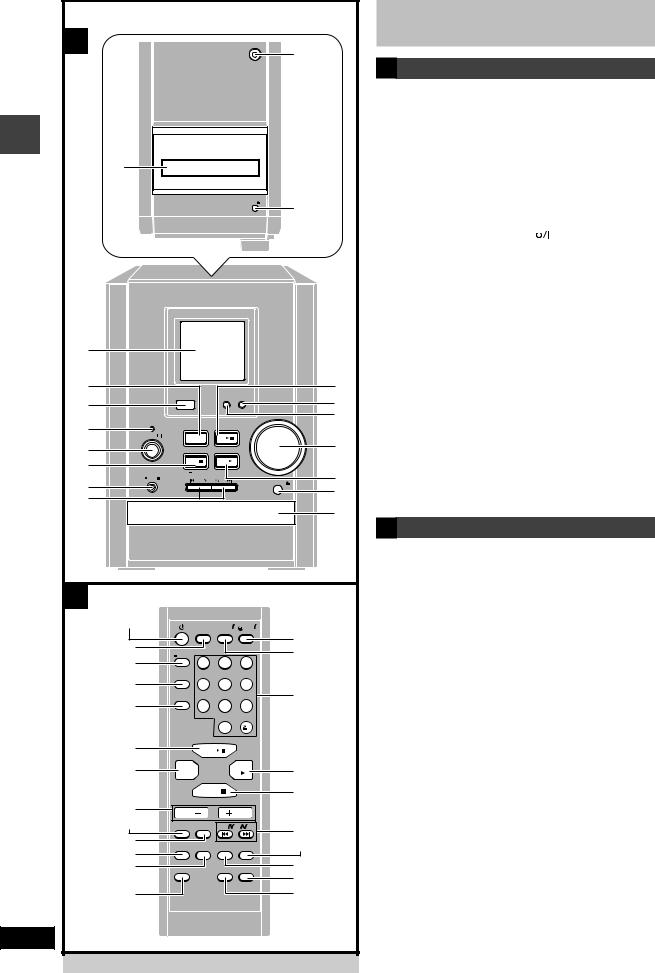
Front panel controls |
|
A Main unit |
|
1Headphone jack (PHONES) ..................................... |
19 |
2Cassette lid |
|
3Cassette eject button (OPEN c) ............................. |
15 |
4Display |
|
5Tuner/band select button (TUNER/BAND) ............. |
10 |
6Remote control signal sensor |
|
7AC supply indicator (AC IN) |
|
This indicator lights when the unit is connected to the AC power supply.
8Standby/on switch (POWER )
Press to switch the unit from on to standby mode or vice versa. In standby mode, the unit is still consuming a small amount of power.
9Stop, demonstration, TAPE/CD mode select button
(STOP L, –DEMO) .................................... |
|
9, 12, 15, 16 |
ÄRecording start/pause button ([REC/ J) |
......... 16, 17 |
|
ÅCD skip/search, tape fast-forward/rewind, tune/ |
||
preset channel select, time adjust buttons |
||
( g/REW/4, 3/FF/ f ) ...... |
9, 10, 11, 12, 14, 15, 20 |
|
ÇCD play/pause button (CD -/ J) ............................. |
12 |
|
ÉPreset EQ select button (PRESET EQ) .................. |
19 |
|
ÑSound Virtualizer button |
|
|
(SOUND VIRTUALIZER) ........................................... |
|
19 |
ÖVolume control (VOLUME DOWN, UP) . 10, 12, 15, 19
ÜCassette play button (TAPE 2) .............................. |
15 |
áCD tray open/close button (OPEN/CLOSE c) ....... |
12 |
àCD Tray |
|
B Remote Control
Buttons such as 8 function in exactly same way as the
buttons on the main unit. |
|
|
âSleep timer button (SLEEP) .................................... |
|
21 |
äCD Program/clear, tuner preset button |
|
|
(PROGRAM/–CLEAR) ........................................ |
|
11, 14 |
ãCD Play mode select button (CD PLAY MODE) |
.... 13 |
|
åCD recording mode button (CD REC MODE) |
........ |
18 |
çFM mode BP button (FM MODE) ....................... |
|
10, 16 |
éTuning mode select button (TUNE MODE) ...... |
|
10, 11 |
èMuting button (MUTING) ......................................... |
|
9 |
êPlay timer/recording timer button |
|
|
(˚PLAY/REC) ........................................................... |
|
20 |
ëClock/timer button (CLOCK/TIMER) ............. |
9, 20, 21 |
|
íNumeric buttons ................................................ |
|
11, 13 |
ìStop, TAPE/CD mode select button (STOP L) ...... |
13 |
|
îTreble button (TREBLE) .......................................... |
|
19 |
ïBass button (BASS) ................................................. |
|
19 |
ñDimmer button (DIMMER) ....................................... |
|
9 |
óDisplay button (DISPLAY) ......................................... |
|
9 |
 Loading...