


Commercial 1750
NordicTrack Commercial 1750, NTL14010.4 User Manual
www.nordictrack.com
,®
CO/V/M 'F C/F L_
Model No. NTL14010.4
Serial No.
Write the serial number in the space
above for reference.
Serial Number
Decal
QUESTIONS?
If you have questions, or if parts are
damaged or missing, DO NOT CON-
TACT THE STORE; please contact
Customer Care.
USER'S
A IAL
IMPORTANT: Please register this
product (see the limited warranty
on the back cover of this manual)
before contacting Customer Care.
CALL TOLL-FREE:
1-800-TO-BE-FIT
(1-800-862-3348)
Mon.-Fri. 6 a.m.-6 p.m. MT
Sat. 8 a.m.-4 p.m. MT
ON THE WEB:
www.nordictrackservice.com
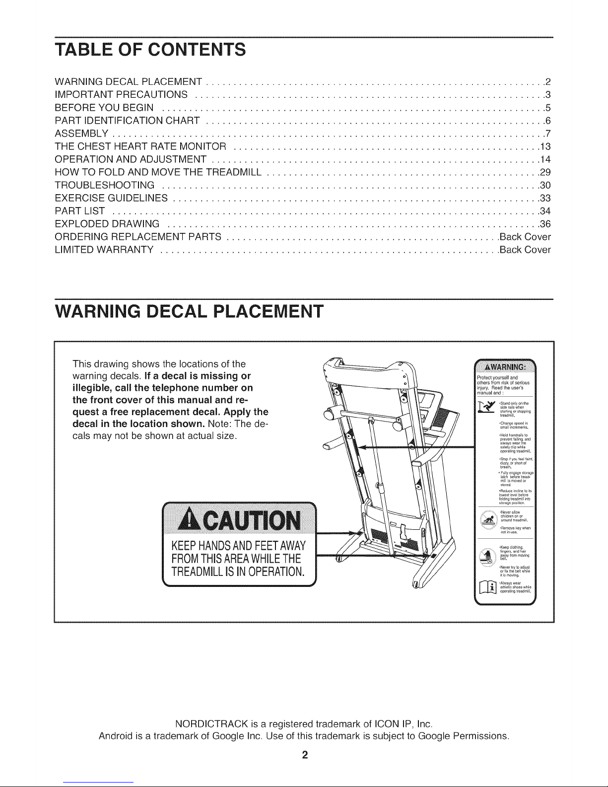
TABLE OF CONTENTS
WARNING DECAL PLACEMENT .............................................................. 2
IMPORTANT PRECAUTIONS ................................................................ 3
BEFORE YOU BEGIN ...................................................................... 5
PART IDENTIFICATION CHART .............................................................. 6
ASSEMBLY ............................................................................... 7
THE CHEST HEART RATE MONITOR ........................................................ 13
OPERATION AND ADJUSTMENT ............................................................ 14
HOW TO FOLD AND MOVE THE TREADMILL .................................................. 29
TROUBLESHOOTING ..................................................................... 30
EXERCISE GUIDELINES ................................................................... 33
PART LIST .............................................................................. 34
EXPLODED DRAWING .................................................................... 36
ORDERING REPLACEMENT PARTS .................................................. Back Cover
LIMITED WARRANTY .............................................................. Back Cover
WARNING DECAL PLACEMENT
This drawing shows the locations of the
warning decals. If a decal is missing or
illegible, call the telephone number on
the front cover of this manual and re-
quest a free replacement decal. Apply the
decal in the location shown. Note: The de-
cals may not be shown at actual size.
KEEPHANDSANDFEETAWAY
FROMTHISAREAWHILETHE
TREADMILLISINOPERATION.
Protect yourself and
others from risk of serious
injury. Read the user's
manual and :
side rails when
• Stand only on the
start ng or slopping
treadmill.
• Change speed n
small ncremen_s.
• Hold handrails to
brevenlialling, and
always wear te
safety tip wNle
operating treadmill.
.stop f you feel faint,
d(zzy, or short of
breath,
•Nevet by to ad ust
or fix the belt while
it is moving.
athletic shoes while
_] .Always wear
operating treadmill.
NORDICTRACK is a registered trademark of ICON IP, Inc.
Android is a trademark of Google Inc. Use of this trademark is subject to Google Permissions.
2

iMPORTANT PRECAUTIONS
WARNING: Toreducetheriskofse.ousinjury, readallimportant precautions andin-
structionsin this manual and all warnings on your treadmill before using your treadmill. ICON as-
sumes no responsibility for personal injury or property damage sustained by or through the use of
this product.
.
Before beginning any exercise program, con-
suit your physician. This is especially impor-
tant for persons over age 35 or persons with
pre-existing health problems.
.
it is the responsibility of the owner to ensure
that all users of this treadmill are adequately
informed of all warnings and precautions.
.
Use the treadmill only as described.
4.
Keep the treadmill indoors, away from mois-
ture and dust. Do not put the treadmill in a
garage or covered patio, or near water.
.
Place the treadmill on a level surface, with at
least 8 ft. (2.4 m) of clearance behind it and 2
ft. (0.6 m) on each side. Do not place the
treadmill on any surface that blocks air open-
ings. To protect the floor or carpet from dam-
age, place a mat under the treadmill.
carrying 15 or more amps. No other appliance
should be on the same circuit. Do not use an
extension cord.
12.
Use only a single-outlet surge suppressor that
meets all of the specifications described on
page 14. To purchase a surge suppressor, see
your local NORDICTRACK dealer or call the
telephone number on the front cover of this
manual and order part number 146148, or see
your local electronics store.
13.
Failure to use a properly functioning surge
suppressor could result in damage to the con-
trol system of the treadmill. If the control sys-
tem is damaged, the walking belt may slow,
accelerate, or stop unexpectedly, which may
result in a fall and serious injury.
!4.
Keep the power cord and the surge suppres-
sor away from heated surfaces.
.
Do not operate the treadmill where aerosol
products are used or where oxygen is being
administered.
.
Keep children under age 12 and pets away
from the treadmill at all times.
.
The treadmill should be used only by persons
weighing 375 Ibs. (170 kg) or less.
.
Never allow more than one person on the
treadmill at a time.
10.
Wear appropriate exercise clothes while
using the treadmill. Do not wear loose clothes
that could become caught in the treadmill. 18.
Athletic support clothes are recommended
for both men and women. Always wear ath-
letic shoes. Never use the treadmill with bare
feet, wearing only stockings, or in sandals. 19.
11.
When connecting the power cord (see page
14), plug the power cord into a surge sup-
pressor (not included) and plug the surge
suppressor into a grounded circuit capable of
15.
Never move the walking belt while the power
is turned off. Do not operate the treadmill if
the power cord or plug is damaged, or if the
treadmill is not working properly. (See TROU-
BLESHOOTING on page 30 if the treadmill is
not working properly.)
16.
Read, understand, and test the emergency
stop procedure before using the treadmill (see
HOW TO TURN ON THE POWER on page 16).
17.
Never start the treadmill while you are stand-
ing on the walking belt. Always hold the
handrails while using the treadmill.
The treadmill is capable of high speeds.
Adjust the speed in small increments to avoid
sudden jumps in speed.
The heart rate monitor is not a medica! de-
vice. Various factors, including the user's
movement, may affect the accuracy of heart
rate readings. The heart rate monitor is in-
tended only as an exercise aid in determining
heart rate trends in general.
20. Never leave the treadmilJ unattended while it 24.
is running. Always remove the key, unplug
the power cord, and press the power switch
into the off position when the treadmill is not 25.
in use. (See the drawing on page 5 for the lo-
cation of the power switch.)
21. Do not attempt to raise, lower, or move the
treadmill until it is properly assembled. (See
ASSEMBLY on page 7, and HOW TO FOLD
AND MOVE THE TREADMILL on page 29.)
You must be able to safely lift 45 Ibs. (20 kg)
to raise, lower, or move the treadmill.
26.
22. When folding or moving the treadmill, make
sure that the storage latch is holding the
frame securely in the storage position.
27.
23. Never insert any object into any opening on
the treadmill
SAVE THESE iNSTRUCTiONS
inspect and properly tighten all parts of the
treadmill regularly.
DANG ER: A waysonp ugthepower
cord immediately after use, before cleaning the
treadmill, and before performing the mainte-
nance and adjustment procedures described in
this manual. Never remove the motor hood un-
less instructed to do so by an authorized ser-
vice representative. Servicing other than the
procedures in this manual should be performed
by an authorized service representative only.
This treadmill is intended for home use only.
Do not use this treadmill in a commercia!,
rental, or institutional setting.
Over exercising may result in serious injury
or death. If you feel faint or if you experience
pain while exercising, stop immediately and
cool down.
4
BEFORE YOU BEGIN
Thank you for selecting the revolutionary
NORDICTRACK ®COMMERCIAL 1750 treadmill. The
COMMERCIAL 1750 treadmill offers an impressive se-
lection of features designed to make your workouts at
home more enjoyable and effective. And when you're
not exercising, the unique treadmill can be folded up,
requiring less than half the floor space of other
treadmills.
For your benefit, read this manual carefully before
using the treadmill. If you have questions after read-
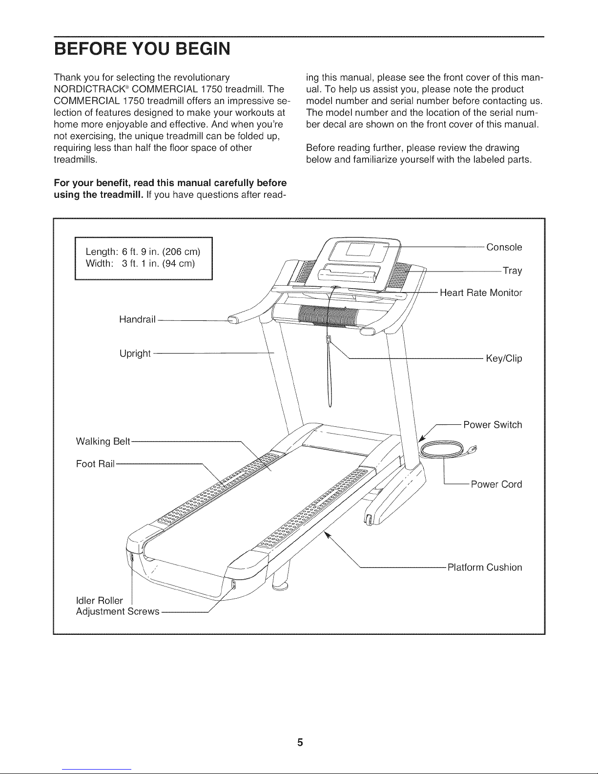
Length: 6 ft. 9 in. (206 cm)
Width: 3 ft. 1 in. (94 cm)
Handrail
Upright
ing this manual, please see the front cover of this man-
ual. To help us assist you, please note the product
model number and serial number before contacting us.
The model number and the location of the serial num-
ber decal are shown on the front cover of this manual.
Before reading further, please review the drawing
below and familiarize yourself with the labeled parts.
Console
Tray
Rate Monitor
Key/Clip
Walking Belt
Foot Rail
Idler Roller
Adjustment Screws
Power Switch
-- Power Cord
Platform Cushion
5
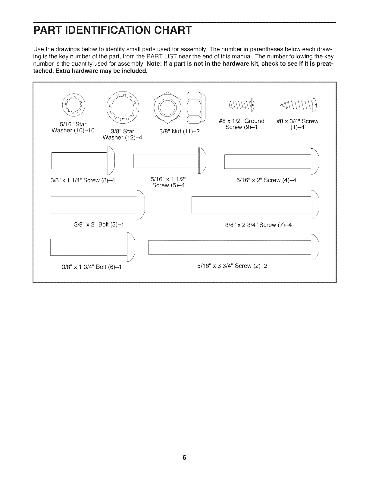
PART iDENTiFiCATiON CHART
Use the drawings below to identify small parts used for assembly. The number in parentheses below each draw-
ing is the key number of the part, from the PART LIST near the end of this manual. The number following the key
number is the quantity used for assembly. Note: If a part is not in the hardware kit, check to see if it is preat=
tached. Extra hardware may be included.
o C>
5/16" Star
Washer (10)-10 3/8" Star
Washer (12)-4
3/8" Nut (11)-2
#8 x 1/2" Ground #8 x 3/4" Screw
Screw (9)-1 (1)-4
3/8" x 1 1/4" Screw (8)-4
3/8" x 2" Bolt (3)-1
3/8" x 1 3/4" Bolt (6)-1
5/16" x 1 1/2"
Screw (5)-4
5/16"x 2" Screw (4)-4
3/8"x 2 3/4" Screw(7)-4
5/16" x 3 3/4" Screw (2)-2
ASSEMBLY
Assembly requires two persons.
Place all parts in a cleared area and remove the
packing materials. Do not dispose of the packing
materials until you finish assembly.
The underside of the walking belt is coated with
high-performance lubricant. After shipping, there
may be some lubricant on top of the walking belt
or on the shipping carton. This is normal. If there
is lubricant on top of the walking belt, wipe it off
with a soft cloth and a mild, non-abrasive cleaner.
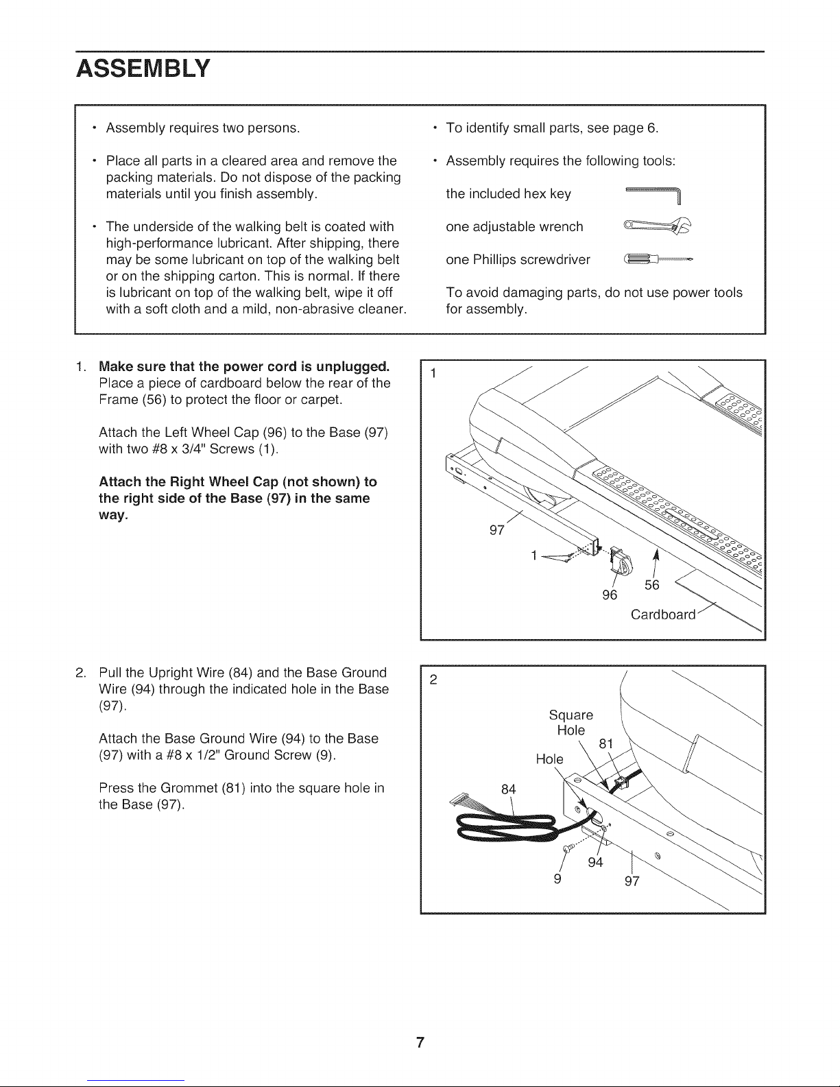
.
Make sure that the power cord is unplugged.
Place a piece of cardboard below the rear of the
Frame (56) to protect the floor or carpet.
Attach the Left Wheel Cap (96) to the Base (97)
with two #8 x 3/4" Screws (1).
Attach the Right Wheel Cap (not shown) to
the right side of the Base (97) in the same
way.
o To identify small parts, see page 6.
o Assembly requires the following tools:
the included hex key
one adjustable wrench
one Phillips screwdriver
To avoid damaging parts, do not use power tools
for assembly.
97
=====7
.
Pull the Upright Wire (84) and the Base Ground
Wire (94) through the indicated hole in the Base
(97).
Attach the Base Ground Wire (94) to the Base
(97) with a #8 x 1/2" Ground Screw (9).
Press the Grommet (81) into the square hole in
the Base (97).
56
96
Square
Hole
Hole
\
84
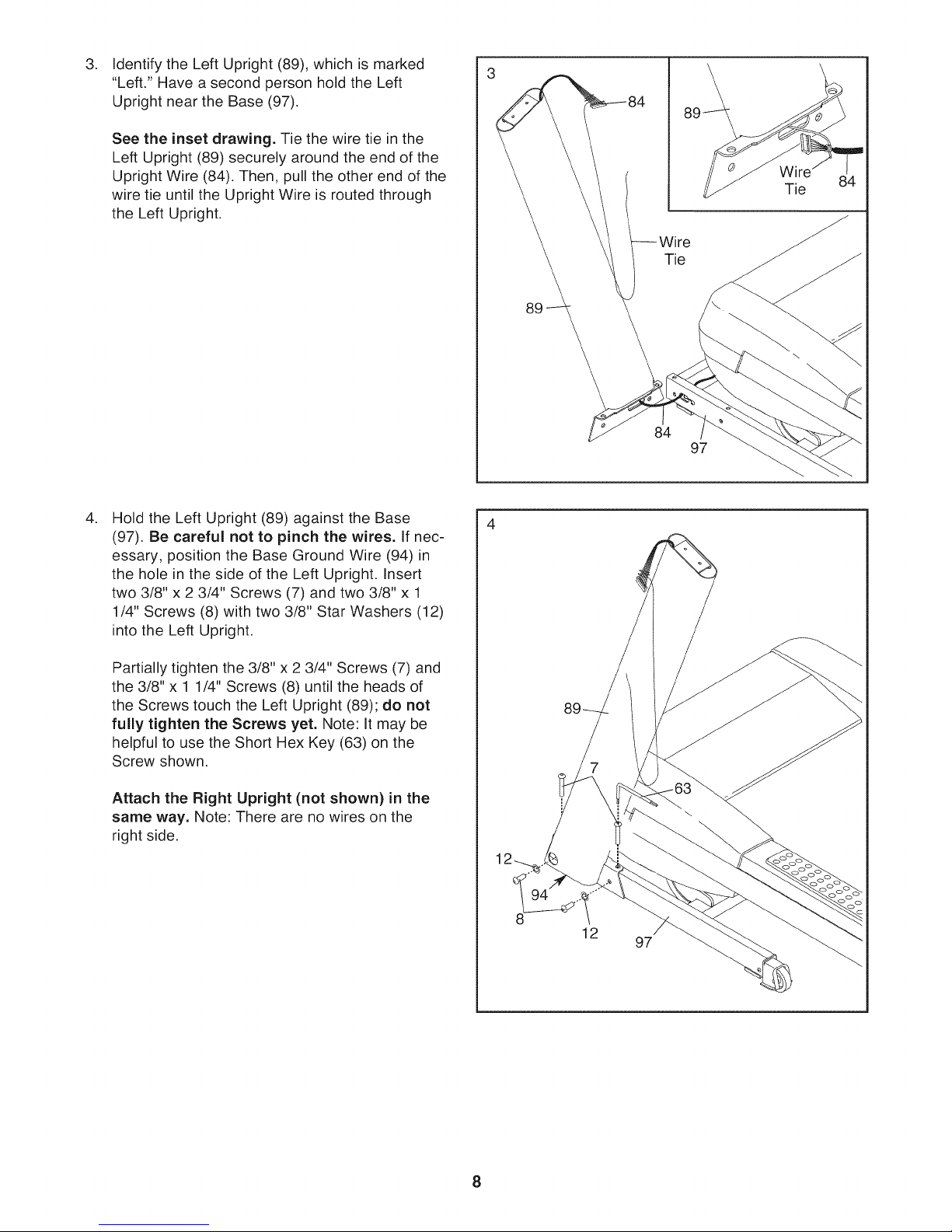
IdentifytheLeftUpright(89),whichismarked
3. 3
"Left."HaveasecondpersonholdtheLeft
UprightneartheBase(97).
Seetheinset drawing. Tie the wire tie in the
Left Upright (89) securely around the end of the
Upright Wire (84), Then, pull the other end of the
wire tie until the Upright Wire is routed through
the Left Upright.
.
Hold the Left Upright (89) against the Base
(97). Be careful not to pinch the wires. If nec-
essary, position the Base Ground Wire (94) in
the hole in the side of the Left Upright. Insert
two 3/8" x 2 3/4" Screws (7) and two 3/8" x 1
1/4" Screws (8) with two 3/8" Star Washers (12)
into the Left Upright.
84
97
Partially tighten the 3/8" x 2 3/4" Screws (7) and
the 3/8" x 1 1/4" Screws (8) until the heads of
the Screws touch the Left Upright (89); do not
fully tighten the Screws yet. Note: It may be
helpful to use the Short Hex Key (63) on the
Screw shown.
Attach the Right Upright (not shown) in the
same way. Note: There are no wires on the
right side.
8
12
97
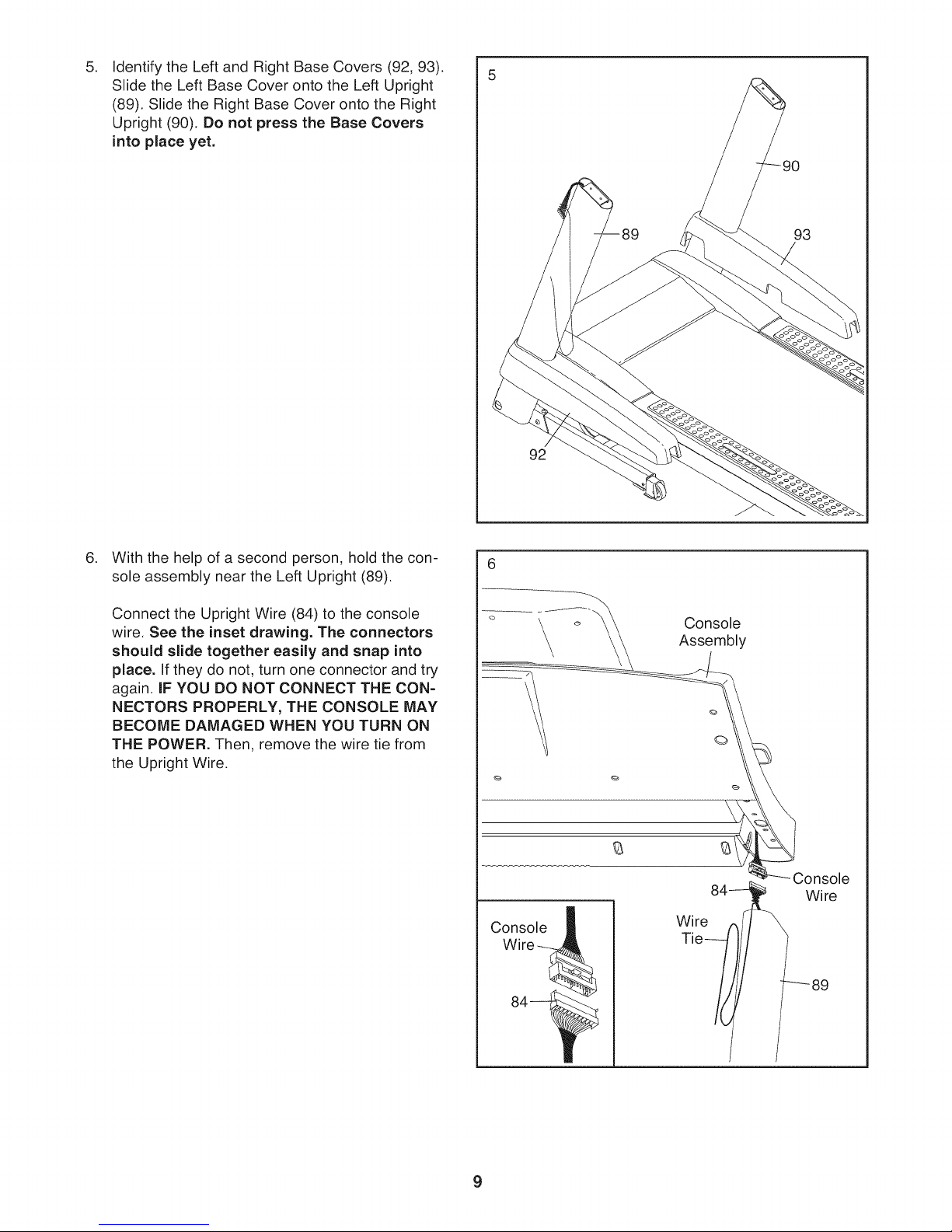
IdentifytheLeftandRightBaseCovers(92,93).
5. 5
SlidetheLeftBaseCoverontotheLeftUpright
(89).SlidetheRightBaseCoverontotheRight
Upright(90).Donot press the Base Covers
into place yet.
92
.
With the help of a second person, hold the con-
sole assembly near the Left Upright (89).
Connect the Upright Wire (84) to the console
wire. See the inset drawing. The connectors
should slide together easily and snap into
place. If they do not, turn one connector and try
again. IF YOU DO NOT CONNECT THE CON-
NECTORS PROPERLY, THE CONSOLE MAY
BECOME DAMAGED WHEN YOU TURN ON
THE POWER. Then, remove the wire tie from
the Upright Wire.
Console
Wire--_
Console
Assembly
Console
Wire
Wi re84_,
Tie/!f!
_89
9
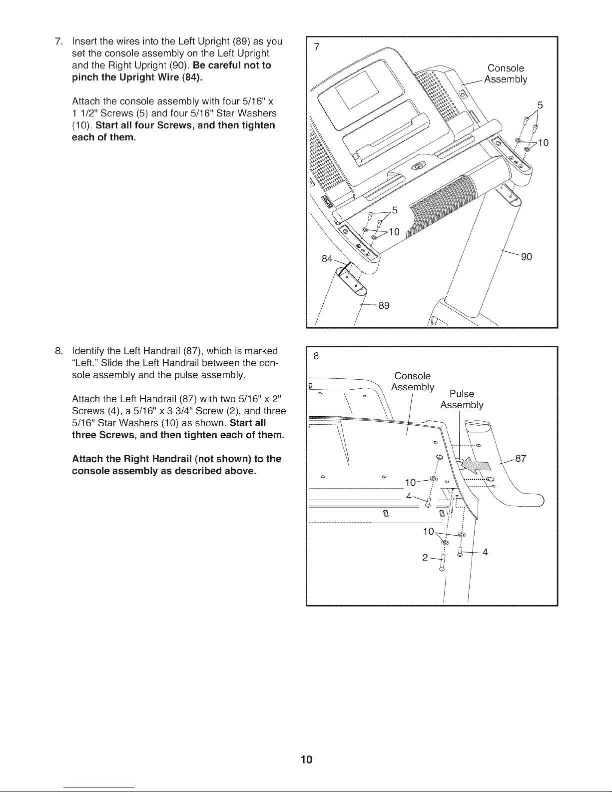
Insert the wires into the Left Upright (89) as you
set the console assembly on the Left Upright
and the Right Upright (90). Be careful not to
pinch the Upright Wire (84).
Attach the console assembly with four 5/16" x
1 1/2" Screws (5) and four 5/16" Star Washers
(10). Start all four Screws, and then tighten
each of them.
Console
Y
,
Identify the Left Handrail (87), which is marked
"Left." Slide the Left Handrail between the con-
sole assembly and the pulse assembly.
Attach the Left Handrail (87) with two 5/16" x 2"
Screws (4), a 5/16" x 3 3/4" Screw (2), and three
5/16" Star Washers (10) as shown. Start all
three Screws, and then tighten each of them.
Attach the Right Handrail (not shown) to the
console assembly as described above.
Console
Assembly
Pulse
Assembly
10
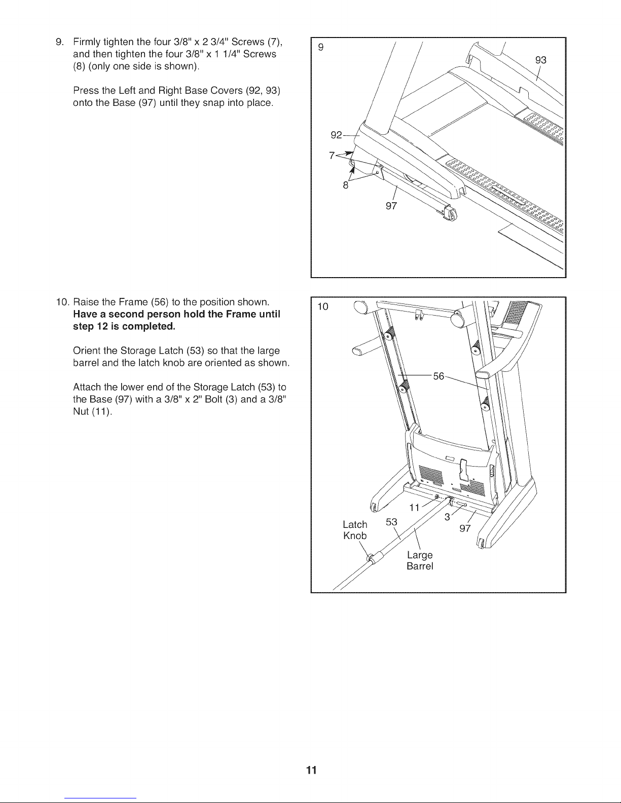
Firmly tighten the four 3/8" x 2 3/4" Screws (7),
9. 9
and then tighten the four 3/8" x 1 1/4" Screws
(8) (only one side is shown).
Press the Left and Right Base Covers (92, 93)
onto the Base (97) until they snap into place.
93
97
10. Raise the Frame (56) to the position shown.
Have a second person hold the Frame until
step 12 is completed.
Orient the Storage Latch (53) so that the large
barrel and the latch knob are oriented as shown.
Attach the lower end of the Storage Latch (53) to
the Base (97) with a 3/8" x 2" Bolt (3) and a 3/8"
Nut (11).
10
Latch 53
Knob
97
Large
Barrel
11
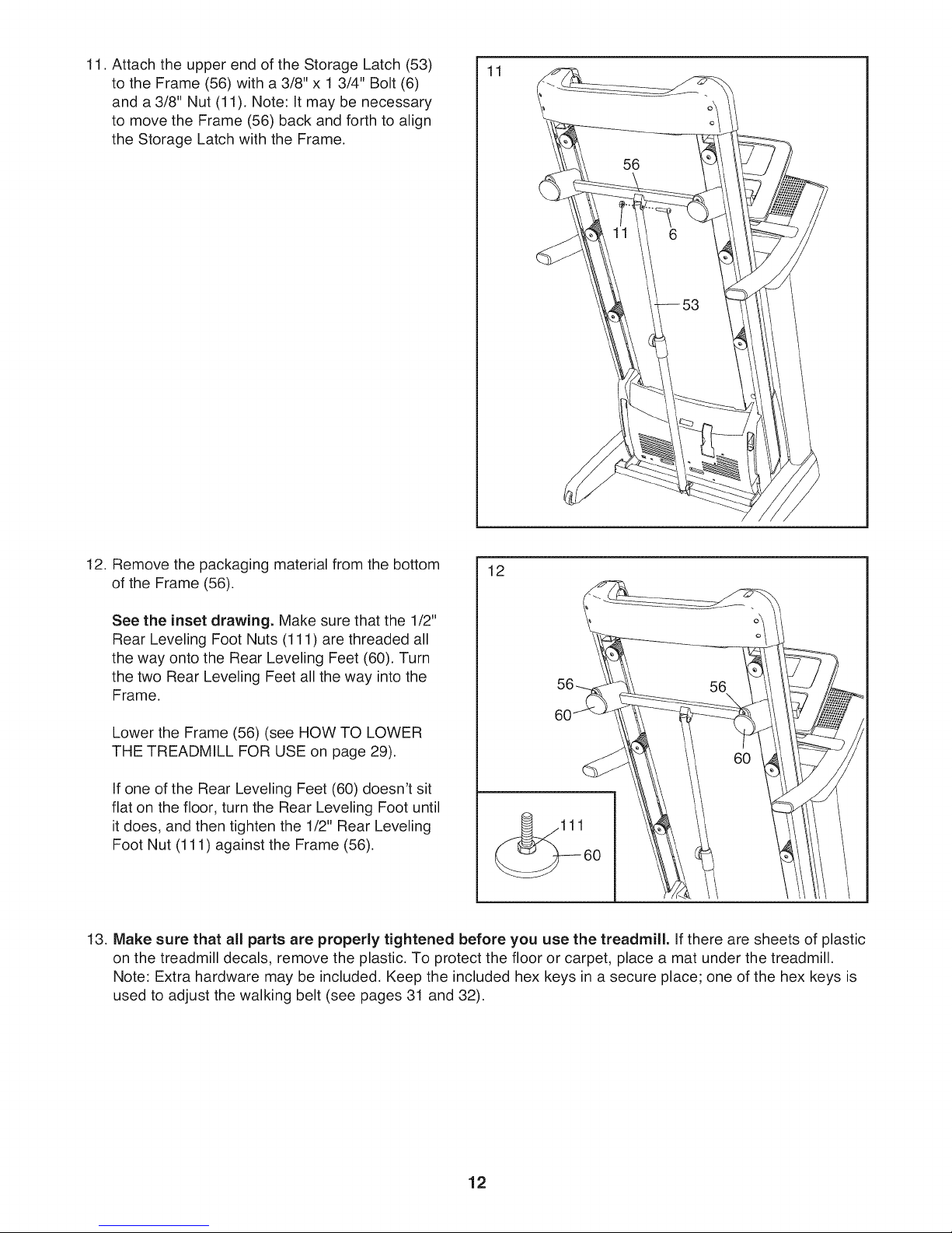
11. Attach the upper end of the Storage Latch (53)
to the Frame (56) with a 3/8" x 1 3/4" Bolt (6)
and a 3/8" Nut (11), Note: It may be necessary
to move the Frame (56) back and forth to align
the Storage Latch with the Frame.
11
12. Remove the packaging material from the bottom
12
of the Frame (56).
See the inset drawing. Make sure that the 1/2"
Rear Leveling Foot Nuts (111) are threaded all
the way onto the Rear Leveling Feet (60), Turn
the two Rear Leveling Feet all the way into the
Frame.
Lower the Frame (56) (see HOW TO LOWER
THE TREADMILL FOR USE on page 29).
60
If one of the Rear Leveling Feet (60) doesn't sit
flat on the floor, turn the Rear Leveling Foot until
it does, and then tighten the 1/2" Rear Leveling
Foot Nut (111) against the Frame (56).
13. Make sure that all parts are properly tightened before you use the treadmill. If there are sheets of plastic
on the treadmill decals, remove the plastic, To protect the floor or carpet, place a mat under the treadmill,
Note: Extra hardware may be included, Keep the included hex keys in a secure place; one of the hex keys is
used to adjust the walking belt (see pages 31 and 32).
12
 Loading...