


 Loading...
Motorola MC68L11E1PB2, MC68L11E20FN2, MC68L11E20FU2, MC68L11E9B2, MC68L11E9FU2 Datasheet
...M68HC11E Family
Technical Data
M68HC11
Microcontrollers
M68HC11E/D
Rev. 4, 7/2002
WWW.MOTOROLA.COM/SEMICONDUCTORS

MC68HC11E Family
Technical Data
To provide the most up-to-date information, the revision of our documents on the World Wide Web will be the most current. Your printed copy may be an earlier revision. To verify you have the latest information available, refer to:
http://www.motorola.com/semiconductors/
The following revision history table summarizes changes contained in this document. For your convenience, the page number designators have been linked to the appropriate location.
Motorola and the Stylized M Logo are registered trademarks of Motorola, Inc. |
|
DigitalDNA is a trademark of Motorola, Inc. |
© Motorola, Inc., 2002 |
0& +& ( )DPLO\ ² 5HY |
7HFKQLFDO 'DWD |
|
|
|
|
027252/$ |
|

5HYLVLRQ +LVWRU\
|
|
Revision History |
|
|
|
|
|
|
|
Date |
Revision |
Description |
Page |
|
Level |
Number(s) |
|||
|
|
|||
|
|
|
|
|
|
|
4.4.3.1 System Configuration Register — Addition to NOCOP bit |
88 |
|
May, 2001 |
3.1 |
description |
||
|
||||
|
|
|||
|
|
Added 11.22 EPROM Characteristics |
251 |
|
|
|
|
|
|
June, 2001 |
3.2 |
11.22 EPROM Characteristics — For clarity, addition to note 2 |
251 |
|
following the table |
||||
|
|
|
||
|
|
|
|
|
December, |
3.3 |
7.8.2 Serial Communications Control Register 1 — SCCR1 bit 4 |
153 |
|
2001 |
(M) description corrected |
|||
|
|
|||
|
|
|
|
|
|
|
11.8 MC68L11E9/E20 DC Electrical Characteristics — Title |
226 |
|
|
|
changed to include the MC68L11E20 |
||
|
|
|
||
|
|
|
|
|
|
|
11.9 MC68L11E9/E20 Supply Currents and Power Dissipation — |
227 |
|
|
|
Title changed to include the MC68L11E20 |
||
|
|
|
||
|
|
|
|
|
|
|
11.11 MC68L11E9/E20 Control Timing — Title changed to include |
230 |
|
|
|
the MC68L11E20 |
||
|
|
|
||
|
|
|
|
|
|
|
11.13 MC68L11E9/E20 Peripheral Port Timing — Title changed to |
236 |
|
|
|
include the MC68L11E20 |
||
|
|
|
||
|
|
|
|
|
July, 2002 |
4 |
11.15 MC68L11E9/E20 Analog-to-Digital Converter |
241 |
|
Characteristics — Title changed to include the MC68L11E20 |
||||
|
|
|
||
|
|
|
|
|
|
|
11.17 MC68L11E9/E20 Expansion Bus Timing Characteristics — |
244 |
|
|
|
Title changed to include the MC68L11E20 |
||
|
|
|
||
|
|
|
|
|
|
|
11.19 MC68L11E9/E20 Serial Peirpheral Interface Characteristics |
247 |
|
|
|
— Title changed to include the MC68L11E20 |
||
|
|
|
||
|
|
|
|
|
|
|
11.21 MC68L11E9/E20 EEPROM Characteristics — Title changed |
250 |
|
|
|
to include the MC68L11E20 |
||
|
|
|
||
|
|
|
|
|
|
|
13.5 Extended Voltage Device Ordering Information (3.0 Vdc to |
267 |
|
|
|
5.5 Vdc) — Updated table to include MC68L1120 |
||
|
|
|
||
|
|
|
|
7HFKQLFDO 'DWD |
0& +& ( )DPLO\ ² 5HY |
|
|
|
|
|
027252/$ |

Technical Data — M68HC11E Family
List of Sections
Section 1. General Description . . . . . . . . . . . . . . . . . . . . 23
Section 2. Pin Descriptions . . . . . . . . . . . . . . . . . . . . . . . 27
Section 3. Central Processor Unit (CPU) . . . . . . . . . . . . 45
Section 4. Operating Modes and On-Chip Memory . . . . 65
Section 5. Resets and Interrupts . . . . . . . . . . . . . . . . . . 107
Section 6. Parallel Input/Output (I/O) Ports . . . . . . . . . 133
Section 7. Serial Communications Interface (SCI) . . . . 145
Section 8. Serial Peripheral Interface (SPI). . . . . . . . . . 165
Section 9. Timing System. . . . . . . . . . . . . . . . . . . . . . . . 177
Section 10. Analog-to-Digital (A/D) Converter . . . . . . . 209
Section 11. Electrical Characteristics . . . . . . . . . . . . . . 221
Section 12. Mechanical Data . . . . . . . . . . . . . . . . . . . . . 253
Section 13. Ordering Information . . . . . . . . . . . . . . . . . 261
Appendix A. Development Support . . . . . . . . . . . . . . . . 269
Appendix B. EVBU Schematic . . . . . . . . . . . . . . . . . . . . 275
MC68HC11E Family — |
Rev. 4 |
Technical Data |
|
|
|
MOTOROLA |
List of Sections |
5 |

List of Sections
AN1060 — M68HC11 Bootstrap Mode . . . . . . . . . . . . . 277
EB184 — Enabling the Security Feature
on the MC68HC711E9 Devices with PCbug11
on the M68HC711E9PGMR . . . . . . . . . . . . . . . . . . . 323
EB188 — Enabling the Security Feature on M68HC811E2 Devices with PCbug11
on the M68HC711E9PGMR . . . . . . . . . . . . . . . . . . . 327
EB296 — Programming MC68HC711E9 Devices
with PCbug11 and the M68HC11EVBU . . . . . . . . . 331
Technical Data |
|
MC68HC11E Family — Rev. 4 |
|
|
|
6 |
List of Sections |
MOTOROLA |

Technical Data — M68HC11E Family
Table of Contents
Section 1. General Description
1.1 Contents . . . . . . . . . . . . . . . . . . . . . . . . . . . . . . . . . . . . . . . . . .23
1.2 Introduction . . . . . . . . . . . . . . . . . . . . . . . . . . . . . . . . . . . . . . . .23
1.3 Features . . . . . . . . . . . . . . . . . . . . . . . . . . . . . . . . . . . . . . . . . .24
1.4 Structure . . . . . . . . . . . . . . . . . . . . . . . . . . . . . . . . . . . . . . . . . .25
Section 2. Pin Descriptions
2.1 Contents . . . . . . . . . . . . . . . . . . . . . . . . . . . . . . . . . . . . . . . . . .27
2.2 Introduction . . . . . . . . . . . . . . . . . . . . . . . . . . . . . . . . . . . . . . . .28
2.3 VDD and VSS . . . . . . . . . . . . . . . . . . . . . . . . . . . . . . . . . . . . . . .32
2.4 RESET . . . . . . . . . . . . . . . . . . . . . . . . . . . . . . . . . . . . . . . . . . .34
2.5Crystal Driver and External Clock Input
(XTAL and EXTAL) . . . . . . . . . . . . . . . . . . . . . . . . . . . . . . .35
2.6 E-Clock Output (E) . . . . . . . . . . . . . . . . . . . . . . . . . . . . . . . . . .36
2.7 Interrupt Request (IRQ) . . . . . . . . . . . . . . . . . . . . . . . . . . . . . .36
2.8 Non-Maskable Interrupt (XIRQ/VPPE). . . . . . . . . . . . . . . . . . . .36
2.9 MODA and MODB (MODA/LIR and MODB/VSTBY) . . . . . . . . .37
2.10 VRL and VRH . . . . . . . . . . . . . . . . . . . . . . . . . . . . . . . . . . . . . . .38
2.11 STRA/AS . . . . . . . . . . . . . . . . . . . . . . . . . . . . . . . . . . . . . . . . .38
2.12 STRB/R/W . . . . . . . . . . . . . . . . . . . . . . . . . . . . . . . . . . . . . . . .38
2.13 Port Signals . . . . . . . . . . . . . . . . . . . . . . . . . . . . . . . . . . . . . . .39
2.13.1 Port A . . . . . . . . . . . . . . . . . . . . . . . . . . . . . . . . . . . . . . . . . .39
2.13.2 Port B . . . . . . . . . . . . . . . . . . . . . . . . . . . . . . . . . . . . . . . . . .41
2.13.3 Port C . . . . . . . . . . . . . . . . . . . . . . . . . . . . . . . . . . . . . . . . . .42
2.13.4 Port D . . . . . . . . . . . . . . . . . . . . . . . . . . . . . . . . . . . . . . . . . .43
2.13.5 Port E . . . . . . . . . . . . . . . . . . . . . . . . . . . . . . . . . . . . . . . . . .43
MC68HC11E Family — |
Rev. 4 |
Technical Data |
|
|
|
MOTOROLA |
Table of Contents |
7 |

Table of Contents
Section 3. Central Processor Unit (CPU)
3.1 Contents . . . . . . . . . . . . . . . . . . . . . . . . . . . . . . . . . . . . . . . . . .45
3.2 Introduction . . . . . . . . . . . . . . . . . . . . . . . . . . . . . . . . . . . . . . . .46
3.3 CPU Registers . . . . . . . . . . . . . . . . . . . . . . . . . . . . . . . . . . . . .46
3.3.1 Accumulators A, B, and D . . . . . . . . . . . . . . . . . . . . . . . . . .47
3.3.2 Index Register X (IX) . . . . . . . . . . . . . . . . . . . . . . . . . . . . . .48
3.3.3 Index Register Y (IY) . . . . . . . . . . . . . . . . . . . . . . . . . . . . . .48
3.3.4 Stack Pointer (SP) . . . . . . . . . . . . . . . . . . . . . . . . . . . . . . . .48
3.3.5 Program Counter (PC) . . . . . . . . . . . . . . . . . . . . . . . . . . . . .50
3.3.6 Condition Code Register (CCR) . . . . . . . . . . . . . . . . . . . . . .51
3.3.6.1 Carry/Borrow (C) . . . . . . . . . . . . . . . . . . . . . . . . . . . . . . .51
3.3.6.2 Overflow (V) . . . . . . . . . . . . . . . . . . . . . . . . . . . . . . . . . . .51
3.3.6.3 Zero (Z) . . . . . . . . . . . . . . . . . . . . . . . . . . . . . . . . . . . . . .51
3.3.6.4 Negative (N). . . . . . . . . . . . . . . . . . . . . . . . . . . . . . . . . . .52
3.3.6.5 Interrupt Mask (I) . . . . . . . . . . . . . . . . . . . . . . . . . . . . . . .52
3.3.6.6 Half Carry (H) . . . . . . . . . . . . . . . . . . . . . . . . . . . . . . . . . .52
3.3.6.7 X Interrupt Mask (X) . . . . . . . . . . . . . . . . . . . . . . . . . . . . .52
3.3.6.8 STOP Disable (S) . . . . . . . . . . . . . . . . . . . . . . . . . . . . . .53
3.4 Data Types . . . . . . . . . . . . . . . . . . . . . . . . . . . . . . . . . . . . . . . .53
3.5 Opcodes and Operands . . . . . . . . . . . . . . . . . . . . . . . . . . . . . .53
3.6 Addressing Modes . . . . . . . . . . . . . . . . . . . . . . . . . . . . . . . . . .54
3.6.1 Immediate. . . . . . . . . . . . . . . . . . . . . . . . . . . . . . . . . . . . . . .54
3.6.2 Direct . . . . . . . . . . . . . . . . . . . . . . . . . . . . . . . . . . . . . . . . . .55
3.6.3 Extended . . . . . . . . . . . . . . . . . . . . . . . . . . . . . . . . . . . . . . .55
3.6.4 Indexed. . . . . . . . . . . . . . . . . . . . . . . . . . . . . . . . . . . . . . . . .55
3.6.5 Inherent . . . . . . . . . . . . . . . . . . . . . . . . . . . . . . . . . . . . . . . .55
3.6.6 Relative . . . . . . . . . . . . . . . . . . . . . . . . . . . . . . . . . . . . . . . .56
3.7 Instruction Set. . . . . . . . . . . . . . . . . . . . . . . . . . . . . . . . . . . . . .56
Technical Data |
|
MC68HC11E Family — Rev. 4 |
|
|
|
8 |
Table of Contents |
MOTOROLA |
Table of Contents
Section 4. Operating Modes and On-Chip Memory
4.1 Contents . . . . . . . . . . . . . . . . . . . . . . . . . . . . . . . . . . . . . . . . . .65
4.2 Introduction . . . . . . . . . . . . . . . . . . . . . . . . . . . . . . . . . . . . . . . .66
4.3 Operating Modes . . . . . . . . . . . . . . . . . . . . . . . . . . . . . . . . . . .66
4.3.1 Single-Chip Mode. . . . . . . . . . . . . . . . . . . . . . . . . . . . . . . . .66
4.3.2 Expanded Mode . . . . . . . . . . . . . . . . . . . . . . . . . . . . . . . . . .67
4.3.3 Test Mode . . . . . . . . . . . . . . . . . . . . . . . . . . . . . . . . . . . . . .67
4.3.4 Bootstrap Mode . . . . . . . . . . . . . . . . . . . . . . . . . . . . . . . . . .68
4.4 Memory Map. . . . . . . . . . . . . . . . . . . . . . . . . . . . . . . . . . . . . . .69
4.4.1 RAM and Input/Output Mapping. . . . . . . . . . . . . . . . . . . . . .80
4.4.2 Mode Selection. . . . . . . . . . . . . . . . . . . . . . . . . . . . . . . . . . .82
4.4.3 System Initialization . . . . . . . . . . . . . . . . . . . . . . . . . . . . . . .85
4.4.3.1 System Configuration Register . . . . . . . . . . . . . . . . . . . .86
4.4.3.2 RAM and I/O Mapping Register . . . . . . . . . . . . . . . . . . . .89
4.4.3.3 System Configuration Options Register. . . . . . . . . . . . . .91
4.5 EPROM/OTPROM . . . . . . . . . . . . . . . . . . . . . . . . . . . . . . . . . .92
4.5.1 Programming an Individual EPROM Address . . . . . . . . . . .93
4.5.2 Programming the EPROM with Downloaded Data. . . . . . . .94
4.5.3EPROM and EEPROM Programming
Control Register . . . . . . . . . . . . . . . . . . . . . . . . . . . . . . .94
4.6 EEPROM . . . . . . . . . . . . . . . . . . . . . . . . . . . . . . . . . . . . . . . . .98
4.6.1 EEPROM and CONFIG Programming and Erasure. . . . . . .98
4.6.1.1 Block Protect Register . . . . . . . . . . . . . . . . . . . . . . . . . . .99
4.6.1.2EPROM and EEPROM Programming
Control Register . . . . . . . . . . . . . . . . . . . . . . . . . . . .101
4.6.1.3 EEPROM Bulk Erase . . . . . . . . . . . . . . . . . . . . . . . . . . .103
4.6.1.4 EEPROM Row Erase. . . . . . . . . . . . . . . . . . . . . . . . . . .103
4.6.1.5 EEPROM Byte Erase. . . . . . . . . . . . . . . . . . . . . . . . . . .104
4.6.1.6 CONFIG Register Programming . . . . . . . . . . . . . . . . . .104
4.6.2 EEPROM Security . . . . . . . . . . . . . . . . . . . . . . . . . . . . . . .104
MC68HC11E Family — |
Rev. 4 |
Technical Data |
|
|
|
MOTOROLA |
Table of Contents |
9 |

Table of Contents
Section 5. Resets and Interrupts
5.1 Contents . . . . . . . . . . . . . . . . . . . . . . . . . . . . . . . . . . . . . . . . .107
5.2 Introduction . . . . . . . . . . . . . . . . . . . . . . . . . . . . . . . . . . . . . . .108
5.3 Resets. . . . . . . . . . . . . . . . . . . . . . . . . . . . . . . . . . . . . . . . . . .108
5.3.1 Power-On Reset (POR) . . . . . . . . . . . . . . . . . . . . . . . . . . .109
5.3.2 External Reset (RESET) . . . . . . . . . . . . . . . . . . . . . . . . . .109
5.3.3 Computer Operating Properly (COP) Reset. . . . . . . . . . . .110
5.3.4 Clock Monitor Reset . . . . . . . . . . . . . . . . . . . . . . . . . . . . . .111
5.3.5 System Configuration Options Register . . . . . . . . . . . . . . .112
5.3.6 Configuration Control Register . . . . . . . . . . . . . . . . . . . . . .113
5.4 Effects of Reset . . . . . . . . . . . . . . . . . . . . . . . . . . . . . . . . . . .114
5.4.1 Central Processor Unit (CPU) . . . . . . . . . . . . . . . . . . . . . .115
5.4.2 Memory Map . . . . . . . . . . . . . . . . . . . . . . . . . . . . . . . . . . .115
5.4.3 Timer . . . . . . . . . . . . . . . . . . . . . . . . . . . . . . . . . . . . . . . . .115
5.4.4 Real-Time Interrupt (RTI) . . . . . . . . . . . . . . . . . . . . . . . . . .116
5.4.5 Pulse Accumulator . . . . . . . . . . . . . . . . . . . . . . . . . . . . . . .116
5.4.6 Computer Operating Properly (COP) . . . . . . . . . . . . . . . . .116
5.4.7 Serial Communications Interface (SCI) . . . . . . . . . . . . . . .116
5.4.8 Serial Peripheral Interface (SPI). . . . . . . . . . . . . . . . . . . . .117
5.4.9 Analog-to-Digital (A/D) Converter. . . . . . . . . . . . . . . . . . . .117
5.4.10 System . . . . . . . . . . . . . . . . . . . . . . . . . . . . . . . . . . . . . . . .117
5.5 Reset and Interrupt Priority. . . . . . . . . . . . . . . . . . . . . . . . . . .117
5.5.1 Highest Priority Interrupt and Miscellaneous Register . . . .119
5.6 Interrupts. . . . . . . . . . . . . . . . . . . . . . . . . . . . . . . . . . . . . . . . .121
5.6.1 Interrupt Recognition and Register Stacking . . . . . . . . . . .122
5.6.2 Non-Maskable Interrupt Request (XIRQ) . . . . . . . . . . . . . .123
5.6.3 Illegal Opcode Trap . . . . . . . . . . . . . . . . . . . . . . . . . . . . . .123
5.6.4 Software Interrupt (SWI). . . . . . . . . . . . . . . . . . . . . . . . . . .124
5.6.5 Maskable Interrupts . . . . . . . . . . . . . . . . . . . . . . . . . . . . . .124
5.6.6 Reset and Interrupt Processing . . . . . . . . . . . . . . . . . . . . .124
5.7 Low-Power Operation . . . . . . . . . . . . . . . . . . . . . . . . . . . . . . .129
5.7.1 Wait Mode . . . . . . . . . . . . . . . . . . . . . . . . . . . . . . . . . . . . .130
5.7.2 Stop Mode . . . . . . . . . . . . . . . . . . . . . . . . . . . . . . . . . . . . .130
Technical Data |
|
MC68HC11E Family — Rev. 4 |
|
|
|
10 |
Table of Contents |
MOTOROLA |
Table of Contents
Section 6. Parallel Input/Output (I/O) Ports
6.1 Contents . . . . . . . . . . . . . . . . . . . . . . . . . . . . . . . . . . . . . . . . .133
6.2 Introduction . . . . . . . . . . . . . . . . . . . . . . . . . . . . . . . . . . . . . . .133
6.3 Port A . . . . . . . . . . . . . . . . . . . . . . . . . . . . . . . . . . . . . . . . . . .134
6.4 Port B . . . . . . . . . . . . . . . . . . . . . . . . . . . . . . . . . . . . . . . . . . .136
6.5 Port C . . . . . . . . . . . . . . . . . . . . . . . . . . . . . . . . . . . . . . . . . . .136
6.6 Port D . . . . . . . . . . . . . . . . . . . . . . . . . . . . . . . . . . . . . . . . . . .138
6.7 Port E . . . . . . . . . . . . . . . . . . . . . . . . . . . . . . . . . . . . . . . . . . .139
6.8 Handshake Protocol . . . . . . . . . . . . . . . . . . . . . . . . . . . . . . . .139
6.9 Parallel I/O Control Register . . . . . . . . . . . . . . . . . . . . . . . . . .141
Section 7. Serial Communications Interface (SCI)
7.1 Contents . . . . . . . . . . . . . . . . . . . . . . . . . . . . . . . . . . . . . . . . .145
7.2 Introduction . . . . . . . . . . . . . . . . . . . . . . . . . . . . . . . . . . . . . . .145
7.3 Data Format . . . . . . . . . . . . . . . . . . . . . . . . . . . . . . . . . . . . . .146
7.4 Transmit Operation . . . . . . . . . . . . . . . . . . . . . . . . . . . . . . . . .146
7.5 Receive Operation . . . . . . . . . . . . . . . . . . . . . . . . . . . . . . . . .148
7.6 Wakeup Feature . . . . . . . . . . . . . . . . . . . . . . . . . . . . . . . . . . .148
7.6.1 Idle-Line Wakeup . . . . . . . . . . . . . . . . . . . . . . . . . . . . . . . .150
7.6.2 Address-Mark Wakeup. . . . . . . . . . . . . . . . . . . . . . . . . . . .150
7.7 SCI Error Detection. . . . . . . . . . . . . . . . . . . . . . . . . . . . . . . . .151
7.8 SCI Registers . . . . . . . . . . . . . . . . . . . . . . . . . . . . . . . . . . . . .152
7.8.1 Serial Communications Data Register . . . . . . . . . . . . . . . .152
7.8.2 Serial Communications Control Register 1 . . . . . . . . . . . .153 7.8.3 Serial Communications Control Register 2 . . . . . . . . . . . .154
7.8.4 Serial Communication Status Register. . . . . . . . . . . . . . . .155
7.8.5 Baud Rate Register . . . . . . . . . . . . . . . . . . . . . . . . . . . . . .157
7.9 Status Flags and Interrupts. . . . . . . . . . . . . . . . . . . . . . . . . . .160
7.10 Receiver Flags . . . . . . . . . . . . . . . . . . . . . . . . . . . . . . . . . . . .162
MC68HC11E Family — |
Rev. 4 |
Technical Data |
|
|
|
MOTOROLA |
Table of Contents |
11 |

Table of Contents
Section 8. Serial Peripheral Interface (SPI)
8.1 |
Contents . . . . . . . . . . . . . . . . . . . . . . . . . . . . . . . . . . . |
. . . . . .165 |
8.2 |
Introduction . . . . . . . . . . . . . . . . . . . . . . . . . . . . . . . . . |
. . . . . .166 |
8.3 |
Functional Description . . . . . . . . . . . . . . . . . . . . . . . . |
. . . . . .166 |
8.4 |
SPI Transfer Formats . . . . . . . . . . . . . . . . . . . . . . . . . . |
. . . . .168 |
8.5 |
Clock Phase and Polarity Controls . . . . . . . . . . . . . . . . |
. . . . .169 |
8.6 |
SPI Signals . . . . . . . . . . . . . . . . . . . . . . . . . . . . . . . . . . |
. . . . .169 |
8.6.1 |
Master In/Slave Out . . . . . . . . . . . . . . . . . . . . . . . . . |
. . . . .170 |
8.6.2 |
Master Out/Slave In . . . . . . . . . . . . . . . . . . . . . . . . . |
. . . . .170 |
8.6.3 |
Serial Clock . . . . . . . . . . . . . . . . . . . . . . . . . . . . . . . |
. . . . .170 |
8.6.4 |
Slave Select . . . . . . . . . . . . . . . . . . . . . . . . . . . . . . . |
. . . . .170 |
8.7 |
SPI System Errors . . . . . . . . . . . . . . . . . . . . . . . . . . . . |
. . . . .171 |
8.8 |
SPI Registers . . . . . . . . . . . . . . . . . . . . . . . . . . . . . . . . |
. . . . .172 |
8.8.1 |
Serial Peripheral Control Register . . . . . . . . . . . . . |
. . . . .173 |
8.8.2 |
Serial Peripheral Status Register . . . . . . . . . . . . . . |
. . . . .175 |
8.8.3 |
Serial Peripheral Data I/O Register . . . . . . . . . . . . . |
. . . . .176 |
|
Section 9. Timing System |
|
9.1 |
Contents . . . . . . . . . . . . . . . . . . . . . . . . . . . . . . . . . . . . |
. . . . .177 |
9.2 |
Introduction . . . . . . . . . . . . . . . . . . . . . . . . . . . . . . . . . . |
. . . . .178 |
9.3 |
Timer Structure . . . . . . . . . . . . . . . . . . . . . . . . . . . . . . . |
. . . . .180 |
9.4 |
Input Capture . . . . . . . . . . . . . . . . . . . . . . . . . . . . . . . . |
. . . . .182 |
9.4.1 |
Timer Control Register 2 . . . . . . . . . . . . . . . . . . . . . |
. . . . .183 |
9.4.2 |
Timer Input Capture Registers . . . . . . . . . . . . . . . . . |
. . . . .184 |
9.4.3 |
Timer Input Capture 4/Output Compare 5 Register . |
. . . . .186 |
9.5 |
Output Compare . . . . . . . . . . . . . . . . . . . . . . . . . . . . . . |
. . . . .186 |
9.5.1 |
Timer Output Compare Registers . . . . . . . . . . . . . . |
. . . . .187 |
9.5.2 |
Timer Compare Force Register . . . . . . . . . . . . . . . . |
. . . . .190 |
9.5.3 |
Output Compare Mask Register. . . . . . . . . . . . . . . . |
. . . . .191 |
9.5.4 |
Output Compare Data Register . . . . . . . . . . . . . . . . |
. . . . .192 |
9.5.5 |
Timer Counter Register . . . . . . . . . . . . . . . . . . . . . . |
. . . . .193 |
9.5.6 |
Timer Control Register 1 . . . . . . . . . . . . . . . . . . . . . |
. . . . .194 |
9.5.7 |
Timer Interrupt Mask 1 Register. . . . . . . . . . . . . . . . |
. . . . .195 |
9.5.8 |
Timer Interrupt Flag 1 Register . . . . . . . . . . . . . . . . |
. . . . .196 |
Technical Data |
MC68HC11E Family — Rev. 4 |
|
12 |
Table of Contents |
MOTOROLA |
Table of Contents
9.5.9 Timer Interrupt Mask 2 Register. . . . . . . . . . . . . . . . . . . . .196
9.5.10 Timer Interrupt Flag Register 2 . . . . . . . . . . . . . . . . . . . . .198
9.6 Real-Time Interrupt (RTI) . . . . . . . . . . . . . . . . . . . . . . . . . . . .199 9.6.1 Timer Interrupt Mask Register 2. . . . . . . . . . . . . . . . . . . . .200 9.6.2 Timer Interrupt Flag Register 2 . . . . . . . . . . . . . . . . . . . . .201 9.6.3 Pulse Accumulator Control Register . . . . . . . . . . . . . . . . .202
9.7 Computer Operating Properly (COP) Watchdog Function . . .203
9.8 Pulse Accumulator . . . . . . . . . . . . . . . . . . . . . . . . . . . . . . . . .203 9.8.1 Pulse Accumulator Control Register . . . . . . . . . . . . . . . . .205 9.8.2 Pulse Accumulator Count Register . . . . . . . . . . . . . . . . . .206 9.8.3 Pulse Accumulator Status and Interrupt Bits . . . . . . . . . . .207
Section 10. Analog-to-Digital (A/D) Converter
10.1 Contents . . . . . . . . . . . . . . . . . . . . . . . . . . . . . . . . . . . . . . . . .209
10.2 Introduction . . . . . . . . . . . . . . . . . . . . . . . . . . . . . . . . . . . . . . .209
10.3 Overview. . . . . . . . . . . . . . . . . . . . . . . . . . . . . . . . . . . . . . . . .210
10.3.1 Multiplexer . . . . . . . . . . . . . . . . . . . . . . . . . . . . . . . . . . . . .210
10.3.2 Analog Converter . . . . . . . . . . . . . . . . . . . . . . . . . . . . . . . .212
10.3.3 Digital Control. . . . . . . . . . . . . . . . . . . . . . . . . . . . . . . . . . .212
10.3.4 Result Registers . . . . . . . . . . . . . . . . . . . . . . . . . . . . . . . . .212
10.3.5 A/D Converter Clocks. . . . . . . . . . . . . . . . . . . . . . . . . . . . .213
10.3.6 Conversion Sequence . . . . . . . . . . . . . . . . . . . . . . . . . . . .213
10.4 A/D Converter Power-Up and Clock Select . . . . . . . . . . . . . .214
10.5 Conversion Process . . . . . . . . . . . . . . . . . . . . . . . . . . . . . . . .215
10.6 Channel Assignments. . . . . . . . . . . . . . . . . . . . . . . . . . . . . . .216
10.7 Single-Channel Operation . . . . . . . . . . . . . . . . . . . . . . . . . . .216
10.8 Multiple-Channel Operation . . . . . . . . . . . . . . . . . . . . . . . . . .217
10.9 Operation in Stop and Wait Modes. . . . . . . . . . . . . . . . . . . . .217
10.10 A/D Control/Status Register . . . . . . . . . . . . . . . . . . . . . . . . . .218
10.11 A/D Converter Result Registers . . . . . . . . . . . . . . . . . . . . . . .220
MC68HC11E Family — |
Rev. 4 |
Technical Data |
|
|
|
MOTOROLA |
Table of Contents |
13 |

Table of Contents
Section 11. Electrical Characteristics
11.1 Contents . . . . . . . . . . . . . . . . . . . . . . . . . . . . . . . . . . . . . . . . .221
11.2 Introduction . . . . . . . . . . . . . . . . . . . . . . . . . . . . . . . . . . . . . . .222
11.3Maximum Ratings for Standard
|
and Extended Voltage Devices . . . . . . . . . . . . . . . . . . . . . |
222 |
11.4 |
Functional Operating Range. . . . . . . . . . . . . . . . . . . . . . . . . . |
223 |
11.5 |
Thermal Characteristics . . . . . . . . . . . . . . . . . . . . . . . . . . . . . |
223 |
11.6 |
DC Electrical Characteristics . . . . . . . . . . . . . . . . . . . . . . . . . |
224 |
11.7 |
Supply Currents and Power Dissipation . . . . . . . . . . . . . . . . . |
225 |
11.8 |
MC68L11E9/E20 DC Electrical Characteristics . . . . . . . . . . . |
226 |
11.9 |
MC68L11E9/E20 Supply Currents and Power Dissipation. . . |
227 |
11.10 |
Control Timing . . . . . . . . . . . . . . . . . . . . . . . . . . . . . . . . . . . . |
229 |
11.11 |
MC68L11E9/E20 Control Timing . . . . . . . . . . . . . . . . . . . . . . |
230 |
11.12 |
Peripheral Port Timing . . . . . . . . . . . . . . . . . . . . . . . . . . . . . . |
235 |
11.13 |
MC68L11E9/E20 Peripheral Port Timing . . . . . . . . . . . . . . . . |
236 |
11.14 |
Analog-to-Digital Converter Characteristics . . . . . . . . . . . . . . |
240 |
11.15 |
MC68L11E9/E20 Analog-to-Digital |
|
|
Converter Characteristics . . . . . . . . . . . . . . . . . . . . . . . . . |
241 |
11.16 |
Expansion Bus Timing Characteristics . . . . . . . . . . . . . . . . . . |
242 |
11.17 |
MC68L11E9/E20 Expansion Bus Timing Characteristics. . . . |
244 |
11.18 |
Serial Peripheral Interface Timing Characteristics . . . . . . . . . |
246 |
11.19 |
MC68L11E9/E20 Serial Peirpheral |
|
|
Interface Characteristics . . . . . . . . . . . . . . . . . . . . . . . . . . |
247 |
11.20 |
EEPROM Characteristics . . . . . . . . . . . . . . . . . . . . . . . . . . . |
250 |
11.21 |
MC68L11E9/E20 EEPROM Characteristics . . . . . . . . . . . . . . |
250 |
11.22 |
EPROM Characteristics . . . . . . . . . . . . . . . . . . . . . . . . . . . . . |
251 |
Technical Data |
|
MC68HC11E Family — Rev. 4 |
|
|
|
14 |
Table of Contents |
MOTOROLA |
Table of Contents
Section 12. Mechanical Data
12.1 Contents . . . . . . . . . . . . . . . . . . . . . . . . . . . . . . . . . . . . . . . . .253
12.2 Introduction . . . . . . . . . . . . . . . . . . . . . . . . . . . . . . . . . . . . . . .253
12.3 52-Pin Plastic-Leaded Chip Carrier (Case 778) . . . . . . . . . . .254
12.452-Pin Windowed Ceramic-Leaded
Chip Carrier (Case 778B) . . . . . . . . . . . . . . . . . . . . . . . . .255 12.5 64-Pin Quad Flat Pack (Case 840C) . . . . . . . . . . . . . . . . . . .256 12.6 52-Pin Thin Quad Flat Pack (Case 848D) . . . . . . . . . . . . . . .257 12.7 56-Pin Dual in-Line Package (Case #859) . . . . . . . . . . . . . . .258 12.8 48-Pin Plastic DIP (Case 767) . . . . . . . . . . . . . . . . . . . . . . . .259
Section 13. Ordering Information
13.1 Contents . . . . . . . . . . . . . . . . . . . . . . . . . . . . . . . . . . . . . . . . .261
13.2 Introduction . . . . . . . . . . . . . . . . . . . . . . . . . . . . . . . . . . . . . . .261
13.3 Standard Device Ordering Information . . . . . . . . . . . . . . . . . .262
13.4 Custom ROM Device Ordering Information . . . . . . . . . . . . . .265
13.5Extended Voltage Device Ordering Information
(3.0 Vdc to 5.5 Vdc) . . . . . . . . . . . . . . . . . . . . . . . . . . . . . .267
Appendix A. Development Support
A.1 Contents . . . . . . . . . . . . . . . . . . . . . . . . . . . . . . . . . . . . . . . . .269 A.2 Introduction . . . . . . . . . . . . . . . . . . . . . . . . . . . . . . . . . . . . . . .269 A.3 Motorola M68HC11 E-Series Development Tools . . . . . . . . .270 A.4 EVS — Evaluation System . . . . . . . . . . . . . . . . . . . . . . . . . . .270 A.5 Motorola Modular Development System (MMDS11) . . . . . . .271 A.6 SPGMR11 — Serial Programmer for M68HC11 MCUs . . . . .273
Appendix B. EVBU Schematic
M68HC11EVBU Schematic. . . . . . . . . . . . . . . . . . . . . . . . . . . . . . . .275
MC68HC11E Family — Rev. 4 |
|
Technical Data |
|
|
|
MOTOROLA |
Table of Contents |
15 |

Table of Contents
AN1060 |
|
AN1060 — M68HC11 Bootstrap Mode . . . . . . . . . . . . . . . . . . . . . . |
277 |
EB184 |
|
EB184 — Enabling the Security Feature on the MC68HC711E9 |
|
Devices with PCbug11 on the M68HC711E9PGMR 323 |
|
EB188 |
|
EB188 — Enabling the Security Feature on M68HC811E2 |
|
Devices with PCbug11 on the M68HC711E9PGMR . . . . . . . . . |
327 |
EB296 |
|
EB296 — Programming MC68HC711E9 Devices |
|
with PCbug11 and the M68HC11EVBU . . . . . . . . . . . . . . . . . . . |
331 |
Technical Data |
|
MC68HC11E Family — Rev. 4 |
|
|
|
16 |
Table of Contents |
MOTOROLA |

Technical Data — M68HC11E Family
List of Figures
Figure |
Title |
Page |
1-1 M68HC11 E-Series Block Diagram . . . . . . . . . . . . . . . . . . . .26
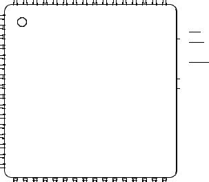
2-1 Pin Assignments for 52-Pin PLCC and CLCC . . . . . . . . . . . .28
2-2 Pin Assignments for 64-Pin QFP . . . . . . . . . . . . . . . . . . . . . .29
2-3 Pin Assignments for 52-Pin TQFP . . . . . . . . . . . . . . . . . . . . .30
2-4 Pin Assignments for 56-Pin SDIP. . . . . . . . . . . . . . . . . . . . . .31 2-5 Pin Assignments for 48-Pin DIP (MC68HC811E2). . . . . . . . .32
2-6 External Reset Circuit. . . . . . . . . . . . . . . . . . . . . . . . . . . . . . .33
2-7 External Reset Circuit with Delay . . . . . . . . . . . . . . . . . . . . . .33 2-8 Common Parallel Resonant Crystal Connections . . . . . . . . .35
2-9 External Oscillator Connections . . . . . . . . . . . . . . . . . . . . . . .35
3-1 Programming Model . . . . . . . . . . . . . . . . . . . . . . . . . . . . . . . .47
3-2 Stacking Operations . . . . . . . . . . . . . . . . . . . . . . . . . . . . . . . .49
4-1 Address/Data Demultiplexing . . . . . . . . . . . . . . . . . . . . . . . . .68
4-2 Memory Map for MC68HC11E0 . . . . . . . . . . . . . . . . . . . . . . .70
4-3 Memory Map for MC68HC11E1 . . . . . . . . . . . . . . . . . . . . . . .70 4-4 Memory Map for MC68HC(7)11E9. . . . . . . . . . . . . . . . . . . . .71
4-5 Memory Map for MC68HC(7)11E20. . . . . . . . . . . . . . . . . . . .71 4-6 Memory Map for MC68HC811E2 . . . . . . . . . . . . . . . . . . . . . .72 4-7 Register and Control Bit Assignments . . . . . . . . . . . . . . . . . .72
4-8 RAM Standby MODB/VSTBY Connections . . . . . . . . . . . . . . .81 4-9 Highest Priority I-Bit Interrupt and Miscellaneous
Register (HPRIO) . . . . . . . . . . . . . . . . . . . . . . . . . . . . . . .83
4-10 System Configuration Register (CONFIG) . . . . . . . . . . . . . . .87 4-11 MC68HC811E2 System Configuration
Register (CONFIG) . . . . . . . . . . . . . . . . . . . . . . . . . . . . . .87
4-12 RAM and I/O Mapping Register (INIT) . . . . . . . . . . . . . . . . . .89
MC68HC11E Family — |
Rev. 4 |
Technical Data |
|
|
|
MOTOROLA |
List of Figures |
17 |

List of Figures
Figure |
Title |
Page |
4-13 |
System Configuration Options Register (OPTION) . |
. . . . . . .91 |
4-14 |
EPROM and EEPROM Programming |
|
|
Control Register (PPROG) . . . . . . . . . . . . . . . . . |
. . . . . . .95 |
4-15 |
MC68HC711E20 EPROM Programming |
|
|
Control Register (EPROG) . . . . . . . . . . . . . . . . . . |
. . . . . .96 |
4-16 |
Block Protect Register (BPROT) . . . . . . . . . . . . . . . . |
. . . . . .99 |
4-17 |
EPROM and EEPROM Programming |
|
|
Control Register (PPROG) . . . . . . . . . . . . . . . . . . |
. . . . .101 |
5-1 |
Arm/Reset COP Timer Circuitry Register (COPRST). |
. . . . .111 |
5-2 |
System Configuration Options Register (OPTION) . . |
. . . . .112 |
5-3 |
Configuration Control Register (CONFIG) . . . . . . . . . |
. . . . .113 |
5-4 |
Highest Priority I-Bit Interrupt |
|
|
and Miscellaneous Register (HPRIO) . . . . . . . . . . |
. . . . .119 |
5-5 |
Processing Flow Out of Reset . . . . . . . . . . . . . . . . . . |
. . . . .125 |
5-6 |
Interrupt Priority Resolution . . . . . . . . . . . . . . . . . . . . |
. . . . .127 |
5-7 |
Interrupt Source Resolution Within SCI . . . . . . . . . . . |
. . . . .129 |
6-1 |
Port A Data Register (PORTA). . . . . . . . . . . . . . . . . . |
. . . . .134 |
6-2 |
Pulse Accumulator Control Register (PACTL) . . . . . . |
. . . . .135 |
6-3 |
Port B Data Register (PORTB). . . . . . . . . . . . . . . . . . |
. . . . .136 |
6-4 |
Port C Data Register (PORTC) . . . . . . . . . . . . . . . . . |
. . . . .136 |
6-5 |
Port C Latched Register (PORTCL) . . . . . . . . . . . . . . |
. . . . .137 |
6-6 |
Port C Data Direction Register (DDRC) . . . . . . . . . . . |
. . . . .137 |
6-7 |
Port D Data Register (PORTD) . . . . . . . . . . . . . . . . . |
. . . . .138 |
6-8 |
Port D Data Direction Register (DDRD) . . . . . . . . . . . |
. . . . .138 |
6-9 |
Port E Data Register (PORTE). . . . . . . . . . . . . . . . . . |
. . . . .139 |
6-10 |
Parallel I/O Control Register (PIOC). . . . . . . . . . . . . . |
. . . . .141 |
7-1 |
SCI Transmitter Block Diagram . . . . . . . . . . . . . . . . . |
. . . . .147 |
7-2 |
SCI Receiver Block Diagram . . . . . . . . . . . . . . . . . . . |
. . . . .149 |
7-3 |
Serial Communications Data Register (SCDR) . . . . . |
. . . . .152 |
7-4 |
Serial Communications Control Register 1 (SCCR1) . |
. . . . .153 |
7-5 |
Serial Communications Control Register 2 (SCCR2) . |
. . . . .154 |
7-6 |
Serial Communications Status Register (SCSR) . . . . |
. . . . .155 |
7-7 |
Baud Rate Register (BAUD). . . . . . . . . . . . . . . . . . . . |
. . . . .157 |
Technical Data |
MC68HC11E Family — Rev. 4 |
|
|
|
|
|
|
|
18 |
List of Figures |
MOTOROLA |
List of Figures
Figure |
Title |
Page |
7-8 SCI Baud Rate Generator Block Diagram . . . . . . . . . . . . . .160 7-9 MC68HC(7)11E20 SCI Baud Rate
Generator Block Diagram . . . . . . . . . . . . . . . . . . . . . . . .161
7-10 Interrupt Source Resolution Within SCI . . . . . . . . . . . . . . . .163
8-1 SPI Block Diagram . . . . . . . . . . . . . . . . . . . . . . . . . . . . . . . .167
8-2 SPI Transfer Format . . . . . . . . . . . . . . . . . . . . . . . . . . . . . . .168 8-3 Serial Peripheral Control Register (SPCR). . . . . . . . . . . . . .173
8-4 Serial Peripheral Status Register (SPSR) . . . . . . . . . . . . . .175
8-5 Serial Peripheral Data I/O Register (SPDR). . . . . . . . . . . . .176
9-1 Timer Clock Divider Chains . . . . . . . . . . . . . . . . . . . . . . . . .179 9-2 Capture/Compare Block Diagram. . . . . . . . . . . . . . . . . . . . .181
9-3 Timer Control Register 2 (TCTL2) . . . . . . . . . . . . . . . . . . . .183
9-4 Timer Input Capture 1 Register Pair (TIC1) . . . . . . . . . . . . .184 9-5 Timer Input Capture 2 Register Pair (TIC2) . . . . . . . . . . . . .185
9-6 Timer Input Capture 3 Register Pair (TIC3) . . . . . . . . . . . . .185
9-7 Timer Input Capture 4/Output
Compare 5 Register Pair (TI4/O5). . . . . . . . . . . . . . . . . .186
9-8 Timer Output Compare 1 Register Pair (TOC1) . . . . . . . . . .188
9-9 Timer Output Compare 2 Register Pair (TOC2) . . . . . . . . . .188 9-10 Timer Output Compare 3 Register Pair (TOC3) . . . . . . . . . .189
9-11 Timer Output Compare 4 Register Pair (TOC4) . . . . . . . . . .189
9-12 Timer Compare Force Register (CFORC) . . . . . . . . . . . . . .190 9-13 Output Compare 1 Mask Register (OC1M) . . . . . . . . . . . . .191
9-14 Output Compare 1 Data Register (OC1D) . . . . . . . . . . . . . .192 9-15 Timer Counter Register (TCNT) . . . . . . . . . . . . . . . . . . . . . .193 9-16 Timer Control Register 1 (TCTL1) . . . . . . . . . . . . . . . . . . . .194 9-17 Timer Interrupt Mask 1 Register (TMSK1) . . . . . . . . . . . . . .195 9-18 Timer Interrupt Flag 1 Register (TFLG1) . . . . . . . . . . . . . . .196 9-19 Timer Interrupt Mask 2 Register (TMSK2) . . . . . . . . . . . . . .196 9-20 Timer Interrupt Flag 2 Register (TFLG2) . . . . . . . . . . . . . . .198 9-21 Timer Interrupt Mask 2 Register (TMSK2) . . . . . . . . . . . . . .200 9-22 Timer Interrupt Flag 2 Register (TFLG2) . . . . . . . . . . . . . . .201
9-23 Pulse Accumulator Control Register (PACTL) . . . . . . . . . . .202 9-24 Pulse Accumulator . . . . . . . . . . . . . . . . . . . . . . . . . . . . . . . .204
MC68HC11E Family — |
Rev. 4 |
Technical Data |
|
|
|
MOTOROLA |
List of Figures |
19 |

List of Figures
Figure |
Title |
Page |
9-25 Pulse Accumulator Control Register (PACTL) . . . . . . . . . . .205 9-26 Pulse Accumulator Count Register (PACNT) . . . . . . . . . . . .206
9-27 Timer Interrupt Mask 2 Register (TMSK2) . . . . . . . . . . . . . .207
9-28 Timer Interrupt Flag 2 Register (TFLG2) . . . . . . . . . . . . . . .207
10-1 A/D Converter Block Diagram . . . . . . . . . . . . . . . . . . . . . . .211
10-2 Electrical Model of an A/D Input Pin (Sample Mode) . . . . . .211 10-3 A/D Conversion Sequence . . . . . . . . . . . . . . . . . . . . . . . . . .213
10-4 System Configuration Options Register (OPTION) . . . . . . .214
10-5 A/D Control/Status Register (ADCTL) . . . . . . . . . . . . . . . . .218
10-6 Analog-to-Digital Converter
Result Registers (ADR1–ADR4) . . . . . . . . . . . . . . . . . . .220
11-1 Test Methods . . . . . . . . . . . . . . . . . . . . . . . . . . . . . . . . . . . .228
11-2 Timer Inputs . . . . . . . . . . . . . . . . . . . . . . . . . . . . . . . . . . . . .230 11-3 POR External Reset Timing Diagram. . . . . . . . . . . . . . . . . .231
11-4 STOP Recovery Timing Diagram . . . . . . . . . . . . . . . . . . . . .232
11-5 WAIT Recovery from Interrupt Timing Diagram . . . . . . . . . .233 11-6 Interrupt Timing Diagram . . . . . . . . . . . . . . . . . . . . . . . . . . .234
11-7 Port Read Timing Diagram . . . . . . . . . . . . . . . . . . . . . . . . . .237
11-8 Port Write Timing Diagram . . . . . . . . . . . . . . . . . . . . . . . . . .237 11-9 Simple Input Strobe Timing Diagram . . . . . . . . . . . . . . . . . .237
11-10 Simple Output Strobe Timing Diagram. . . . . . . . . . . . . . . . .238
11-11 Port C Input Handshake Timing Diagram. . . . . . . . . . . . . . .238 11-12 Port C Output Handshake Timing Diagram . . . . . . . . . . . . .238
11-13 3-State Variation of Output Handshake Timing Diagram (STRA Enables Output Buffer) . . . . . . . . . . . . . . . . . . . .239
11-14 Multiplexed Expansion Bus Timing Diagram . . . . . . . . . . . .245 11-15 SPI Timing Diagram . . . . . . . . . . . . . . . . . . . . . . . . . . . . . . .248
B-1 EVBU Schematic Diagram . . . . . . . . . . . . . . . . . . . . . . . . . .276
Technical Data |
|
MC68HC11E Family — Rev. 4 |
|
|
|
20 |
List of Figures |
MOTOROLA |
Technical Data — M68HC11E Family
List of Tables
Table |
Title |
Page |
2-1 Port Signal Functions . . . . . . . . . . . . . . . . . . . . . . . . . . . . . . . .40
3-1 Reset Vector Comparison. . . . . . . . . . . . . . . . . . . . . . . . . . . . .50
3-2 Instruction Set. . . . . . . . . . . . . . . . . . . . . . . . . . . . . . . . . . . . . .57
4-1 Hardware Mode Select Summary. . . . . . . . . . . . . . . . . . . . . . .82
4-2 Write Access Limited Registers . . . . . . . . . . . . . . . . . . . . . . . .85
4-3 EEPROM Mapping . . . . . . . . . . . . . . . . . . . . . . . . . . . . . . . . . .88
4-4 RAM Mapping . . . . . . . . . . . . . . . . . . . . . . . . . . . . . . . . . . . . . .90
4-5 Register Mapping . . . . . . . . . . . . . . . . . . . . . . . . . . . . . . . . . . .90
4-6 EEPROM Block Protect . . . . . . . . . . . . . . . . . . . . . . . . . . . . .100
4-7 EEPROM Block Protect in MC68HC811E2 MCUs . . . . . . . . .100
4-8 EEPROM Erase . . . . . . . . . . . . . . . . . . . . . . . . . . . . . . . . . . .102
5-1 COP Timer Rate Select . . . . . . . . . . . . . . . . . . . . . . . . . . . . .110 5-2 Reset Cause, Reset Vector, and Operating Mode . . . . . . . . .114
5-3 Highest Priority Interrupt Selection . . . . . . . . . . . . . . . . . . . . .120
5-4 Interrupt and Reset Vector Assignments . . . . . . . . . . . . . . . .121 5-5 Stacking Order on Entry to Interrupts . . . . . . . . . . . . . . . . . . .122
6-1 Input/Output Ports. . . . . . . . . . . . . . . . . . . . . . . . . . . . . . . . . .133
6-2 Parallel I/O Control . . . . . . . . . . . . . . . . . . . . . . . . . . . . . . . . .143
7-1 Baud Rate Values. . . . . . . . . . . . . . . . . . . . . . . . . . . . . . . . . .158
8-1 SPI Clock Rates . . . . . . . . . . . . . . . . . . . . . . . . . . . . . . . . . . .174
9-1 Timer Summary . . . . . . . . . . . . . . . . . . . . . . . . . . . . . . . . . . .180
9-2 Timer Control Configuration . . . . . . . . . . . . . . . . . . . . . . . . . .183
MC68HC11E Family — |
Rev. 4 |
Technical Data |
|
|
|
MOTOROLA |
List of Tables |
21 |

List of Tables
Table |
Title |
Page |
9-3 Timer Output Compare Actions . . . . . . . . . . . . . . . . . . . . . . .194
9-4 Timer Prescale . . . . . . . . . . . . . . . . . . . . . . . . . . . . . . . . . . . .197
9-5 RTI Rates . . . . . . . . . . . . . . . . . . . . . . . . . . . . . . . . . . . . . . . .199
9-6 Pulse Accumulator Timing . . . . . . . . . . . . . . . . . . . . . . . . . . .204
9-7 Pulse Accumulator Edge Control . . . . . . . . . . . . . . . . . . . . . .205
10-1 Converter Channel Assignments . . . . . . . . . . . . . . . . . . . . . .216
10-2 A/D Converter Channel Selection. . . . . . . . . . . . . . . . . . . . . .219
Technical Data |
|
MC68HC11E Family — Rev. 4 |
|
|
|
22 |
List of Tables |
MOTOROLA |

Technical Data — M68HC11E Family
Section 1. General Description
1.1 Contents
1.2 Introduction . . . . . . . . . . . . . . . . . . . . . . . . . . . . . . . . . . . . . . . .23
1.3 Features . . . . . . . . . . . . . . . . . . . . . . . . . . . . . . . . . . . . . . . . . .24
1.4 Structure . . . . . . . . . . . . . . . . . . . . . . . . . . . . . . . . . . . . . . . . . .25
1.2 Introduction
This document contains a detailed description of the M68HC11 E series of 8-bit microcontroller units (MCUs). These MCUs all combine the M68HC11 central processor unit (CPU) with high-performance, on-chip peripherals.
The E series is comprised of many devices with various configurations of:
•Random-access memory (RAM)
•Read-only memory (ROM)
•Erasable programmable read-only memory (EPROM)
•Electrically erasable programmable read-only memory
(EEPROM)
•Several low-voltage devices are also available.
With the exception of a few minor differences, the operation of all E-series MCUs is identical. A fully static design and high-density complementary metal-oxide semiconductor (HCMOS) fabrication process allow the E-series devices to operate at frequencies from 3 MHz to dc with very low power consumption.
MC68HC11E Family — |
Rev. 4 |
Technical Data |
|
|
|
MOTOROLA |
General Description |
23 |

General Description
1.3 Features
Features of the E-series devices include:
•M68HC11 CPU
•Power-saving stop and wait modes
•Low-voltage devices available (3.0–5.5 Vdc)
•0, 256, 512, or 768 bytes of on-chip RAM, data retained during standby
•0, 12, or 20 Kbytes of on-chip ROM or EPROM
•0, 512, or 2048 bytes of on-chip EEPROM with block protect for security
•2048 bytes of EEPROM with selectable base address in the
MC68HC811E2
•Asynchronous non-return-to-zero (NRZ) serial communications interface (SCI)
•Additional baud rates available on MC68HC(7)11E20
•Synchronous serial peripheral interface (SPI)
•8-channel, 8-bit analog-to-digital (A/D) converter
•16-bit timer system:
–Three input capture (IC) channels
–Four output compare (OC) channels
–One additional channel, selectable as fourth IC or fifth OC
•8-bit pulse accumulator
•Real-time interrupt circuit
•Computer operating properly (COP) watchdog system
•38 general-purpose input/output (I/O) pins:
–16 bidirectional I/O pins
–11 input-only pins
–11 output-only pins
Technical Data |
|
MC68HC11E Family — Rev. 4 |
|
|
|
24 |
General Description |
MOTOROLA |
General Description
Structure
•Several packaging options:
–52-pin plastic-leaded chip carrier (PLCC)
–52-pin windowed ceramic leaded chip carrier (CLCC)
–52-pin plastic thin quad flat pack, 10 mm x 10 mm (TQFP)
–64-pin quad flat pack (QFP)
–48-pin plastic dual in-line package (DIP), MC68HC811E2 only
–56-pin plastic shrink dual in-line package, .070-inch lead spacing (SDIP)
1.4 Structure
See Figure 1-1 for a functional diagram of the E-series MCUs.
Differences among devices are noted in the table accompanying
Figure 1-1.
MC68HC11E Family — |
Rev. 4 |
Technical Data |
|
|
|
MOTOROLA |
General Description |
25 |

General Description
MODA/ |
MODB/ |
XTAL EXTAL E |
|
|
|
|
|
LIR |
VSTBY |
IRQ |
|
XIRQ/VPPE* RESET |
|||
MODE CONTROL
COP |
|
TIMER |
INTERRUPT |
|||||
|
|
|
|
|||||
|
|
|
SYSTEM |
|
||||
|
|
|
|
|
|
|
PERIODIC |
|
ACCUMULATOR |
|
|
|
|
|
|||
OC2 OC3 OC4 OC5/IC4/OC1 IC1 IC2 IC3 |
||||||||
PAI |
||||||||
PULSE |
|
|
|
|
|
|
||
|
|
|
|
|
|
|
|
|
|
|
|
|
|
|
|
|
|
PORT A
OSC
INTERRUPT
LOGIC
CLOCK LOGIC
M68HC11 CPU
ROM OR EPROM (SEE TABLE)
EEPROM
(SEE TABLE)
RAM
(SEE TABLE)
|
BUS EXPANSION |
|
ADDRESS/DATA |
|
R/W |
|
|
|||||||||||||||
|
|
ADDRESS |
|
|
AS |
|||||||||||||||||
|
|
|
|
|
|
|
|
|
|
|
|
|||||||||||
|
|
|
|
|
|
|
|
|
|
|
|
|
|
|
|
|||||||
|
|
|
|
|
|
|
|
|
|
|
|
|
|
|
|
|
|
|
|
|
|
|
|
|
|
|
|
|
|
|
|
|
|
|
|
|
|
|
|
|
|
|
|
|
|
|
|
|
|
|
|
|
|
|
|
|
|
|
|
|
|
|
|
|
|
|
|
|
STROBE AND HANDSHAKE |
STRB |
STRA |
|
|
PARALLEL I/O |
||
|
|
||
|
CONTROL |
|
|
PORT B |
PORT C |
|
|
SERIAL |
|
SERIAL |
|
|
|
|
|
|
|
|
PERIPHERAL |
COMMUNICATION |
|
|
|
|
|
|
|
VDD |
|
|
|
|
|
|
|
|
||||
INTERFACE |
INTERFACE |
|
|
|
|
|
|
|
VSS |
|
SPI |
|
SCI |
|
|
|
|
|
|
|
|
|
|
|
|
|
|
|
|
|
|
|
|
|
|
|
|
|
|
|
|
|
|
SS SCK MOSI MISO |
TxD RxD |
VRH |
VRL |
||
|
|
A/D CONVERTER |
CONTROL |
|
|
PORT D |
|
PORT E |
|
|
|
PA7/PAI PA6/OC2/OC1 PA5/OC3/OC1 PA4/OC4/OC1 PA3/OC5/IC4/OC1 PA2/IC1 PA1/IC2 PA0/IC3 |
PB7/ADDR15 PB6/ADDR14 PB5/ADDR13 PB4/ADDR12 PB3/ADDR11 PB2/ADDR10 PB1/ADDR9 PB0/ADDR8 |
PC7/ADDR7/DATA7 PC6/ADDR6/DATA6 PC5/ADDR5/DATA5 PC4/ADDR4/DATA4 PC3/ADDR3/DATA3 PC2/ADDR2/DATA2 PC1/ADDR1/DATA1 PC0/ADDR0/DATA0 |
|
STRB/R/W |
STRA/AS |
|
PD5/SS |
PD4/SCK PD3/MOSI PD2/MISO PD1/TxD |
PD0/RxD |
PE7/AN7 PE6/AN6 PE5/AN5 PE4/AN4 PE3/AN3 PE2/AN2 PE1/AN1 PE0/AN0 |
||
|
|
|||||||||||
|
|
|
|
|
|
DEVICE |
|
|
RAM |
ROM |
EPROM |
EEPROM |
|
|
|
|
|
|
MC68HC11E0 |
512 |
— |
— |
— |
||
|
|
|
|
|
|
MC68HC11E1 |
512 |
— |
— |
512 |
||
|
|
|
|
|
|
MC68HC11E9 |
512 |
12 K |
— |
512 |
||
|
|
|
|
|
|
MC68HC711E9 |
512 |
— |
12 K |
512 |
||
|
|
|
|
|
|
MC68HC11E20 |
768 |
20 K |
— |
512 |
||
|
|
|
|
|
|
MC68HC711E20 |
768 |
— |
20 K |
512 |
||
|
|
|
|
|
|
MC68HC811E2 |
256 |
— |
— |
2048 |
||
* VPPE applies only to devices with EPROM/OTPROM.
Figure 1-1. M68HC11 E-Series Block Diagram
Technical Data |
|
MC68HC11E Family — Rev. 4 |
|
|
|
26 |
General Description |
MOTOROLA |

Technical Data — M68HC11E Family
Section 2. Pin Descriptions
2.1 Contents
2.2 Introduction . . . . . . . . . . . . . . . . . . . . . . . . . . . . . . . . . . . . . . . .28
2.3 VDD and VSS . . . . . . . . . . . . . . . . . . . . . . . . . . . . . . . . . . . . . . .32
2.4 RESET . . . . . . . . . . . . . . . . . . . . . . . . . . . . . . . . . . . . . . . . . . .34
2.5Crystal Driver and External Clock Input
(XTAL and EXTAL) . . . . . . . . . . . . . . . . . . . . . . . . . . . . . . .35
2.6 E-Clock Output (E) . . . . . . . . . . . . . . . . . . . . . . . . . . . . . . . . . .36
2.7 Interrupt Request (IRQ) . . . . . . . . . . . . . . . . . . . . . . . . . . . . . .36
2.8 Non-Maskable Interrupt (XIRQ/VPPE). . . . . . . . . . . . . . . . . . . .36
2.9 MODA and MODB (MODA/LIR and MODB/VSTBY) . . . . . . . . .37
2.10 VRL and VRH . . . . . . . . . . . . . . . . . . . . . . . . . . . . . . . . . . . . . . .38
2.11 STRA/AS . . . . . . . . . . . . . . . . . . . . . . . . . . . . . . . . . . . . . . . . .38
2.12 STRB/R/W . . . . . . . . . . . . . . . . . . . . . . . . . . . . . . . . . . . . . . . .38
2.13 Port Signals . . . . . . . . . . . . . . . . . . . . . . . . . . . . . . . . . . . . . . .39
2.13.1 Port A . . . . . . . . . . . . . . . . . . . . . . . . . . . . . . . . . . . . . . . . . .39
2.13.2 Port B . . . . . . . . . . . . . . . . . . . . . . . . . . . . . . . . . . . . . . . . . .41
2.13.3 Port C . . . . . . . . . . . . . . . . . . . . . . . . . . . . . . . . . . . . . . . . . .42
2.13.4 Port D . . . . . . . . . . . . . . . . . . . . . . . . . . . . . . . . . . . . . . . . . .43
2.13.5 Port E . . . . . . . . . . . . . . . . . . . . . . . . . . . . . . . . . . . . . . . . . .43
MC68HC11E Family — |
Rev. 4 |
Technical Data |
|
|
|
MOTOROLA |
Pin Descriptions |
27 |
Pin Descriptions
2.2 Introduction
M68HC11 E-series MCUs are available packaged in:
•52-pin plastic-leaded chip carrier (PLCC)
•52-pin windowed ceramic leaded chip carrier (CLCC)
•52-pin plastic thin quad flat pack, 10 mm x 10 mm (TQFP)
•64-pin quad flat pack (QFP)
•48-pin plastic dual in-line package (DIP), MC68HC811E2 only
•56-pin plastic shrink dual in-line package, .070-inch lead spacing
(SDIP)
Most pins on these MCUs serve two or more functions, as described in the following paragraphs. Refer to Figure 2-1, Figure 2-2, Figure 2-3,
Figure 2-4, and Figure 2-5 which show the M68HC11 E-series pin assignments for the PLCC/CLCC, QFP, TQFP, SDIP, and DIP packages.
|
|
|
|
|
|
|
|
|
|
|
|
STRB/R/W |
|
|
STRA/AS |
|
MODA/LIR |
|
STBY |
|
|
|
|
|
|
|
|
PE7/AN7 |
|
|
|
|
|
|
|
|
|
|
|
|
|
|
|
|
|
|
|
|
|
|
|
|
|||||||
|
|
|
|
|
|
|
|
|
|
EXTAL |
E |
|
|
MODB/V |
|
SS |
RH |
|
RL |
||||||||||
|
|
|
|
|
|
|
|
|
|
|
|
|
|
||||||||||||||||
|
|
|
|
|
|
|
|
|
|
|
|
V |
V |
V |
|||||||||||||||
|
|
|
|
|
|
|
|
|
|
|
|
|
|
|
|
|
|
|
|
|
|
|
|
|
|
|
|
|
|
|
|
|
|
|
|
|
|
|
|
|
|
|
|
|
|
|
|
|
|
|
|
|
|
|
|
|
|
|
|
|
|
|
|
|
|
|
|
|
7 |
|
6 |
|
5 |
|
4 |
3 |
2 |
|
|
|
52 |
|
51 |
|
50 |
||||
|
|
|
XTAL |
|
|
8 |
|
|
|
|
|
|
|
|
|
|
|
1 |
|
|
|
|
|
|
|
||||
|
|
|
|
|
|
|
|
|
|
|
|
|
|
|
|
|
|
|
|
|
|
|
|||||||
|
|
|
|
|
|
|
|
|
|
|
|
|
|
|
|
|
|
|
|
|
|
|
|
|
|||||
PC0/ADDR0/DATA0 |
|
|
9 |
|
|
|
|
|
|
|
|
|
|
|
|
|
|
|
|
|
|
|
|
||||||
|
|
|
|
|
|
|
|
|
|
|
|
|
|
|
|
|
|
|
|||||||||||
|
|
|
|
|
|
|
|
|
|
|
|
|
|
|
|
|
|
|
|||||||||||
PC1/ADDR1/DATA1 |
|
|
10 |
|
|
|
|
|
|
|
|
|
|
|
|
|
|
|
|
|
|
|
|
||||||
|
|
|
|
|
|
|
|
|
|
|
|
|
|
|
|
|
|
|
|||||||||||
|
|
|
|
|
|
|
|
|
|
|
|
|
|
|
|
|
|
|
|||||||||||
PC2/ADDR2/DATA2 |
|
|
11 |
|
|
|
|
|
|
|
|
|
|
|
|
|
|
|
|
|
|
|
|
||||||
|
|
|
|
|
|
|
|
|
|
|
|
|
|
|
|
|
|
|
|||||||||||
|
|
|
|
|
|
|
|
|
|
|
|
|
|
|
|
|
|
|
|||||||||||
PC3/ADDR3/DATA3 |
|
|
12 |
|
|
|
|
|
|
|
|
|
|
|
|
|
|
|
|
|
|
|
|
||||||
|
|
|
|
|
|
|
|
|
|
|
|
|
|
|
|
|
|
|
|||||||||||
|
|
|
|
|
|
|
|
|
|
|
|
|
|
|
|
|
|
|
|||||||||||
PC4/ADDR4/DATA4 |
|
|
13 |
|
|
|
|
|
|
|
|
|
|
|
|
|
|
|
|
|
|
|
|
||||||
|
|
|
|
|
|
|
|
|
|
|
|
|
|
|
|
|
|
|
|||||||||||
|
|
|
|
|
|
|
|
|
|
|
|
|
|
|
|
|
|
|
|||||||||||
PC5/ADDR5/DATA5 |
|
|
14 |
|
|
|
|
|
|
|
M68HC11 E SERIES |
||||||||||||||||||
|
|
|
|
|
|
||||||||||||||||||||||||
|
|
|
|
|
|
||||||||||||||||||||||||
PC6/ADDR6/DATA6 |
|
|
15 |
|
|
|
|
|
|
|
|
|
|
|
|
|
|
|
|
|
|
|
|
||||||
|
|
|
|
|
|
|
|
|
|
|
|
|
|
|
|
|
|
|
|||||||||||
|
|
|
|
|
|
|
|
|
|
|
|
|
|
|
|
|
|
|
|||||||||||
PC7/ADDR7/DATA7 |
|
|
16 |
|
|
|
|
|
|
|
|
|
|
|
|
|
|
|
|
|
|
|
|
||||||
|
|
|
|
|
|
|
|
|
|
|
|
|
|
|
|
|
|
|
|||||||||||
|
|
|
|
|
|
|
|
|
|
|
|
|
|
|
|
|
|
|
|||||||||||
|
|
|
|
|
|
|
|
|
|
|
|
|
|
|
|
|
|
|
|
|
|
|
|
|
|
|
|
|
|
|
|
RESET |
|
|
17 |
|
|
|
|
|
|
|
|
|
|
|
|
|
|
|
|
|
|
|
|
||||
|
|
|
|
|
|
|
|
|
|
|
|
|
|
|
|
|
|
|
|
|
|||||||||
|
|
|
|
|
|
|
18 |
|
|
|
|
|
|
|
|
|
|
|
|
|
|
|
|
|
|
|
|
||
* |
XIRQ/VPPE |
|
|
|
|
|
|
|
|
|
|
|
|
|
|
|
|
|
|
|
|
||||||||
|
|
|
|
|
|
|
|
|
|
|
|
|
|
|
|
|
|
|
|||||||||||
|
|
|
|
IRQ |
|
|
|
|
19 |
|
|
|
|
|
|
|
|
|
|
|
|
|
|
|
|
|
|
|
|
|
|
|
|
|
|
|
|
|
|
|
|
|
|
|
|
|
|
|
|
|
|
|
|
|
|
|
|
||
|
|
20 |
|
|
|
|
|
|
|
|
|
|
|
|
|
|
|
|
|
|
|
|
|||||||
|
PD0/RxD |
|
|
|
|
|
|
|
|
|
|
|
|
|
|
|
|
|
|
|
|
|
|
||||||
|
|
|
|
|
|
|
|
|
|
|
|
|
|
|
|
|
|
|
|
|
|
||||||||
|
|
|
|
|
|
|
|
|
21 |
|
22 |
|
23 |
|
24 |
25 |
26 |
27 |
|
28 |
|
29 |
|
30 |
|||||
|
|
|
|
|
|
|
|
|
|
|
|
|
|
|
|
|
|
|
|
|
|
|
|
|
|
|
|
|
|
|
|
|
|
|
|
|
|
|
|
PD1/TxD |
PD2/MISO |
PD3/MOSI |
PD4/SCK |
|
PD5/SS |
V |
|
PA7/PAI/OC1 |
PA6/OC2/OC1 |
|
PA5/OC3/OC1 |
PA4/OC4/OC1 |
|||||||
|
|
|
|
|
|
|
|
|
|
|
|
|
|
|
|
|
|
|
|
DD |
|
|
|
|
|
|
|
|
|
* VPPE applies only to devices with EPROM/OTPROM.
PE3/AN3 |
|
PE6/AN6 |
|
PE2/AN2 |
|
|
|
|
|
|
|
|
|
|
|
|
|
|
|
|
49 |
48 |
47 |
|
|
||
|
|
|
|
|
|
|
46 |
|
PE5/AN5 |
45 |
|
PE1/AN1 |
|
||
44 |
|
PE4/AN4 |
|
||
43 |
|
PE0/AN0 |
|
||
42 |
|
PB0/ADDR8 |
|
||
41 |
|
PB1/ADDR9 |
|
||
40 |
|
PB2/ADDR10 |
|
||
39 |
|
PB3/ADDR11 |
|
||
38 |
|
PB4/ADDR12 |
|
||
37 |
|
PB5/ADDR13 |
|
||
36 |
|
PB6/ADDR14 |
|
||
35 |
|
PB7/ADDR15 |
|
||
34 |
|
PA0/IC3 |
|
31 |
32 |
33 |
||
|
|
|
|
|
PA3/OC5/IC4/OC1 |
PA2/IC1 |
PA1/IC2 |
||
Figure 2-1. Pin Assignments for 52-Pin PLCC and CLCC
Technical Data |
|
MC68HC11E Family — Rev. 4 |
|
|
|
28 |
Pin Descriptions |
MOTOROLA |
Pin Descriptions
Introduction
|
|
|
|
|
|
|
|
PA1/IC2 |
PA2/IC1 |
PA3/OC5/IC4/OC1 |
NC |
NC |
PA4/OC4/OC1 |
PA5/OC3/OC1 |
PA6/OC2/OC1 |
PA7/PAI/OC1 |
V |
|
PD5/SS |
PD4/SCK |
PD3/MOSI |
PD2/MISO |
PD1/TxD |
V |
||||||||||||||||||||||||||||||||||||||||||||||||||||||||||||
|
|
|
|
|
|
|
|
|
||||||||||||||||||||||||||||||||||||||||||||||||||||||||||||||||||||||||||||
|
|
|
|
|
|
|
|
|
||||||||||||||||||||||||||||||||||||||||||||||||||||||||||||||||||||||||||||
|
|
|
|
|
|
|
|
|
|
|
|
|
|
|
|
|
|
|
|
|
|
|
|
|
|
|
|
|
|
|
|
|
|
|
|
|
|
|
|
|
|
|
|
|
|
|
|
|
|
|
|
|
|
|
DD |
|
|
|
|
|
|
|
|
|
|
|
|
|
|
|
|
|
|
|
|
|
|
|
|
SS |
||||
|
|
|
|
|
|
|
|
|
|
|
|
|
|
|
|
|
|
|
|
|
|
|
|
|
|
|
|
|
|
|
|
|
|
|
|
|
|
|
|
|
|
|
|
|
|
|
|
|
|
|
|
|
|
|
|
|
|
|
|
|
|
|
|
|
|
|
|
|
|
|
|
|
|
|
|
|
|
|
|
|
|
|
|
|
|
|
|
|
|
|
|
|
|
|
|
|
|
|
|
|
|
|
|
|
|
|
|
|
|
|
|
|
|
|
|
|
|
|
|
|
|
|
|
|
|
|
|
|
|
|
|
|
|
|
|
|
|
|
|
|
|
|
|
|
|
|
|
|
|
|
|
|
|
|
|
|
|
|
|
|
|
|
|
|
|
|
|
|
|
|
|
|
|
|
|
|
|
|
|
|
|
|
|
|
|
|
|
|
|
|
|
|
|
|
|
|
|
|
|
|
|
|
|
|
|
|
|
|
|
|
|
|
|
|
|
|
|
|
|
|
|
|
|
|
|
|
|
|
|
|
|
|
|
|
|
|
|
|
|
|
|
|
|
|
|
|
|
|
|
|
|
|||
|
|
|
|
|
|
|
|
|
|
|
|
|
|
|
|
|
|
|
|
|
|
|
|
|
|
|
|
|
|
|
|
|
|
|
|
|
|
|
|
|
|
|
|
|
|
|
|
|
|
|
|
|
|
|
|
|
|
|
|
|
|
|
|
|
|
|
|
|
|
|
|
|
|
|
|
|
|
|
|
|
|
|||
PA0/IC3 |
|
|
|
|
|
|
1 |
64 |
63 |
|
|
62 |
|
|
61 |
60 |
|
59 |
58 |
|
|
57 |
|
|
56 |
55 |
|
54 |
53 |
52 |
|
|
51 |
50 |
49 |
|||||||||||||||||||||||||||||||||||||||||||||||||
|
|
|
|
|
|
|
|
|
|
|
|
|
|
|
|
|
|
|
|
|
|
|
|
|
|
|
|
|
|
|
|
|
|
|
|
|
|
|
|
|
|
|
|
|
|
|
|
|
|
|
|
|
|
|
|
|
|
|
|
|
|
|
|
|
|
|
|
|
|
|
|
|
|
|
|
|
|
48 |
||||||
|
|
|
|
|
|
|
|
|
|
|
|
|
|
|
|
|
|
|
|
|
|
|
|
|
|
|
|
|
|
|
|
|
|
|
|
|
|
|
|
|
|
|
|
|
|
|
|
|
|
|
|
|
|
|
|
|
|
|
|
|
|
|
|
|
|
|
|
|
|
|
|
|
|
|
|
|
||||||||
NC |
|
|
2 |
|
|
|
|
|
|
|
|
|
|
|
|
|
|
|
|
|
|
|
|
|
|
|
|
|
|
|
|
|
|
|
|
|
|
|
|
|
|
|
|
|
|
|
|
|
|
|
|
|
|
|
|
|
|
|
|
|
|
|
|
|
|
|
|
|
|
|
|
|
|
|
|
47 |
||||||||
|
|
|
|
|
|
|
|
|
|
|
|
|
|
|
|
|
|
|
|
|
|
|
|
|
|
|
|
|
|
|
|
|
|
|
|
|
|
|
|
|
|
|
|
|
|
|
|
|
|
|
|
|
|
|
|
|
|
|
|
|
|
|
|
|
|
|
|
|
|
|
|
|
|
|
||||||||||
NC |
|
|
3 |
|
|
|
|
|
|
|
|
|
|
|
|
|
|
|
|
|
|
|
|
|
|
|
|
|
|
|
|
|
|
|
|
|
|
|
|
|
|
|
|
|
|
|
|
|
|
|
|
|
|
|
|
|
|
|
|
|
|
|
|
|
|
|
|
|
|
|
|
|
|
|
|
46 |
||||||||
|
|
|
|
|
|
|
|
|
|
|
|
|
|
|
|
|
|
|
|
|
|
|
|
|
|
|
|
|
|
|
|
|
|
|
|
|
|
|
|
|
|
|
|
|
|
|
|
|
|
|
|
|
|
|
|
|
|
|
|
|
|
|
|
|
|
|
|
|
|
|
|
|
|
|
||||||||||
NC |
|
|
4 |
|
|
|
|
|
|
|
|
|
|
|
|
|
|
|
|
|
|
|
|
|
|
|
|
|
|
|
|
|
|
|
|
|
|
|
|
|
|
|
|
|
|
|
|
|
|
|
|
|
|
|
|
|
|
|
|
|
|
|
|
|
|
|
|
|
|
|
|
|
|
|
|
45 |
||||||||
|
|
|
|
|
|
|
|
|
|
|
|
|
|
|
|
|
|
|
|
|
|
|
|
|
|
|
|
|
|
|
|
|
|
|
|
|
|
|
|
|
|
|
|
|
|
|
|
|
|
|
|
|
|
|
|
|
|
|
|
|
|
|
|
|
|
|
|
|
|
|
|
|
|
|
||||||||||
PB7/ADDR15 |
|
|
|
|
|
5 |
|
|
|
|
|
|
|
|
|
|
|
|
|
|
|
|
|
|
|
|
|
|
|
|
|
|
|
|
|
|
|
|
|
|
|
|
|
|
|
|
|
|
|
|
|
|
|
|
|
|
|
|
|
|
|
|
|
|
|
|
|
|
|
|
|
|
|
|
|
|
|
|
44 |
|||||
|
|
|
|
|
|
|
|
|
|
|
|
|
|
|
|
|
|
|
|
|
|
|
|
|
|
|
|
|
|
|
|
|
|
|
|
|
|
|
|
|
|
|
|
|
|
|
|
|
|
|
|
|
|
|
|
|
|
|
|
|
|
|
|
|
|
|
|
|
|
|
|
|
|
|
|
|
||||||||
PB6/ADDR14 |
|
|
|
|
|
6 |
|
|
|
|
|
|
|
|
|
|
|
|
|
|
|
|
|
|
|
|
|
|
|
|
|
|
|
|
|
|
|
|
|
|
|
|
|
|
|
|
|
|
|
|
|
|
|
|
|
|
|
|
|
|
|
|
|
|
|
|
|
|
|
|
|
|
|
|
|
|
|
|
43 |
|||||
|
|
|
|
|
|
|
|
|
|
|
|
|
|
|
|
|
|
|
|
|
|
|
|
|
|
|
|
|
|
|
|
|
|
|
|
|
|
|
|
|
|
|
|
|
|
|
|
|
|
|
|
|
|
|
|
|
|
|
|
|
|
|
|
|
|
|
|
|
|
|
|
|
|
|
|
|
||||||||
PB5/ADDR13 |
|
|
7 |
|
|
|
|
|
|
|
|
|
|
|
|
|
|
|
|
|
|
|
|
|
|
|
|
|
|
|
|
|
|
|
|
|
|
|
|
|
|
|
|
|
|
|
|
|
|
|
|
|
|
|
|
|
|
|
|
|
|
|
|
|
|
|
|
|
|
|
|
|
|
|
|
42 |
||||||||
|
|
|
|
|
|
|
|
|
|
|
|
|
|
|
|
|
|
|
|
|
|
|
|
|
|
|
|
|
|
|
|
|
|
|
|
|
|
|
|
|
|
|
|
|
|
|
|
|
|
|
|
|
|
|
|
|
|
|
|
|
|
|
|
|
|
|
|
|
|
|
|
|
|
|
||||||||||
PB4/ADDR12 |
|
|
8 |
|
|
|
|
|
|
|
|
|
|
|
|
|
|
|
|
|
|
|
|
|
|
M68HC11 E SERIES |
|
|
|
|
|
|
|
|
|
|
|
|
|
41 |
||||||||||||||||||||||||||||||||||||||||||||
|
|
|
|
|
|
|
|
|
|
|
|
|
|
|
|
|
|
|
|
|
|
|
|
|
|
|
|
|
|
|
|
|
|
|
|
|
|
|||||||||||||||||||||||||||||||||||||||||||||||
PB3/ADDR11 |
|
|
|
9 |
|
|
|
|
|
|
|
|
|
|
|
|
|
|
|
|
|
|
|
|
|
|
|
|
|
|
|
|
|
|
|
|
|
|
|
40 |
||||||||||||||||||||||||||||||||||||||||||||
|
|
|
|
|
|
|
|
|
|
|
|
|
|
|
|
|
|
|
|
|
|
|
|
|
|
|
|
|
|
|
|
|
|
|
|
|
|
|
|
|
|
|
|
|
|
|
|
|
|
|
|
|
|
|
|
|
|
|
|
|
|
|
|
|
|
|
|
|
|
|
|
|
|
|
||||||||||
PB2/ADDR10 |
|
|
|
|
|
10 |
|
|
|
|
|
|
|
|
|
|
|
|
|
|
|
|
|
|
|
|
|
|
|
|
|
|
|
|
|
|
|
|
|
|
|
|
|
|
|
|
|
|
|
|
|
|
|
|
|
|
|
|
|
|
|
|
|
|
|
|
|
|
|
|
|
|
|
|
|
|
|
39 |
||||||
|
|
|
|
|
|
|
|
|
|
|
|
|
|
|
|
|
|
|
|
|
|
|
|
|
|
|
|
|
|
|
|
|
|
|
|
|
|
|
|
|
|
|
|
|
|
|
|
|
|
|
|
|
|
|
|
|
|
|
|
|
|
|
|
|
|
|
|
|
|
|
|
|
|
|
|
|||||||||
PB1/ADDR9 |
|
|
|
|
|
11 |
|
|
|
|
|
|
|
|
|
|
|
|
|
|
|
|
|
|
|
|
|
|
|
|
|
|
|
|
|
|
|
|
|
|
|
|
|
|
|
|
|
|
|
|
|
|
|
|
|
|
|
|
|
|
|
|
|
|
|
|
|
|
|
|
|
|
|
|
|
|
|
38 |
||||||
|
|
|
|
|
|
|
|
|
|
|
|
|
|
|
|
|
|
|
|
|
|
|
|
|
|
|
|
|
|
|
|
|
|
|
|
|
|
|
|
|
|
|
|
|
|
|
|
|
|
|
|
|
|
|
|
|
|
|
|
|
|
|
|
|
|
|
|
|
|
|
|
|
|
|
|
|||||||||
PB0/ADDR8 |
|
|
|
|
|
12 |
|
|
|
|
|
|
|
|
|
|
|
|
|
|
|
|
|
|
|
|
|
|
|
|
|
|
|
|
|
|
|
|
|
|
|
|
|
|
|
|
|
|
|
|
|
|
|
|
|
|
|
|
|
|
|
|
|
|
|
|
|
|
|
|
|
|
|
|
|
|
|
37 |
||||||
|
|
|
|
|
|
|
|
|
|
|
|
|
|
|
|
|
|
|
|
|
|
|
|
|
|
|
|
|
|
|
|
|
|
|
|
|
|
|
|
|
|
|
|
|
|
|
|
|
|
|
|
|
|
|
|
|
|
|
|
|
|
|
|
|
|
|
|
|
|
|
|
|
|
|
|
|||||||||
PE0/AN0 |
|
|
|
|
|
13 |
|
|
|
|
|
|
|
|
|
|
|
|
|
|
|
|
|
|
|
|
|
|
|
|
|
|
|
|
|
|
|
|
|
|
|
|
|
|
|
|
|
|
|
|
|
|
|
|
|
|
|
|
|
|
|
|
|
|
|
|
|
|
|
|
|
|
|
|
|
|
|
36 |
||||||
|
|
|
|
|
|
|
|
|
|
|
|
|
|
|
|
|
|
|
|
|
|
|
|
|
|
|
|
|
|
|
|
|
|
|
|
|
|
|
|
|
|
|
|
|
|
|
|
|
|
|
|
|
|
|
|
|
|
|
|
|
|
|
|
|
|
|
|
|
|
|
|
|
|
|
|
|||||||||
PE4/AN4 |
|
|
|
|
|
14 |
|
|
|
|
|
|
|
|
|
|
|
|
|
|
|
|
|
|
|
|
|
|
|
|
|
|
|
|
|
|
|
|
|
|
|
|
|
|
|
|
|
|
|
|
|
|
|
|
|
|
|
|
|
|
|
|
|
|
|
|
|
|
|
|
|
|
|
|
|
|
|
35 |
||||||
|
|
|
|
|
|
|
|
|
|
|
|
|
|
|
|
|
|
|
|
|
|
|
|
|
|
|
|
|
|
|
|
|
|
|
|
|
|
|
|
|
|
|
|
|
|
|
|
|
|
|
|
|
|
|
|
|
|
|
|
|
|
|
|
|
|
|
|
|
|
|
|
|
|
|
|
|||||||||
PE1/AN1 |
|
|
|
|
|
15 |
|
|
|
|
|
|
|
|
|
|
|
|
|
|
|
|
|
|
|
|
|
|
|
|
|
|
|
|
|
|
|
|
|
|
|
|
|
|
|
|
|
|
|
|
|
|
|
|
|
|
|
|
|
|
|
|
|
|
|
|
|
|
|
|
|
|
|
|
|
|
|
34 |
||||||
|
|
|
|
|
|
|
|
|
|
|
|
|
|
|
|
|
|
|
|
|
|
|
|
|
|
|
|
|
|
|
|
|
|
|
|
|
|
|
|
|
|
|
|
|
|
|
|
|
|
|
|
|
|
|
|
|
|
|
|
|
|
|
|
|
|
|
|
|
|
|
|
|
|
|
|
|||||||||
PE5/AN5 |
|
|
|
|
|
|
16 |
|
|
|
|
18 |
|
19 |
|
20 |
|
|
21 |
|
|
22 |
|
|
23 |
|
24 |
|
25 |
|
|
26 |
|
|
27 |
|
|
28 |
29 |
|
|
30 |
|
|
31 |
33 |
||||||||||||||||||||||||||||||||||||||
|
|
|
|
|
|
|
|
17 |
|
|
|
|
|
|
|
|
|
|
|
|
|
|
|
|
|
|
|
|
32 |
|
|
|||||||||||||||||||||||||||||||||||||||||||||||||||||
|
|
|
|
|
|
|
|
|
|
|
|
|
|
|
|
|
|
|
|
|
|
|
|
|
||||||||||||||||||||||||||||||||||||||||||||||||||||||||||||
|
|
|
|
|
|
|
|
|
|
|
|
|
|
|
|
|
|
|
|
|
|
|
|
|
|
|
|
|
|
|
|
|
|
|
|
|
|
|
|
|
|
|
|
|
|
|
|
|
|
|
|
|
|
|
|
|
|
|
|
|
|
|
|
|
|
|
|
|
|
|
|
|
|
|
|
|
|
|
|
|
|
|
|
|
|
|
|
|
|
|
|
|
PE2/AN2 |
PE6/AN6 |
PE3/AN3 |
PE7/AN7 |
V |
V |
V |
V |
MODB/V |
NC |
|
MODA/LIR |
STRA/AS |
E |
STRB/R/W |
EXTAL |
NC |
||||||||||||||||||||||||||||||||||||||||||||||||||||||||||||
|
|
|
|
|
|
|
|
|
|
|
|
|
|
|
|
|
|
|
|
|
|
|
|
|
|
|
|
|
|
RL |
|
|
RH |
|
|
SS |
|
|
SS |
|
|
STBY |
|
|
|
|
|
|
|
|
|
|
|
|
|
|
|
|
|
|
|
|
|
|
|
|
|
|
|
|
|
|
|
|
||||||||||
|
|
|
|
|
|
|
|
|
|
|
|
|
|
|
|
|
|
|
|
|
|
|
|
|
|
|
|
|
|
|
|
|
|
|
|
|
|
|
|
|
|
|
|
|
|
|
|
|
|
|
|
|
|
|
|
|
|
|
|
|
|
|
|
|
|
|
|
|
|
|
|
|
|
|
|
|
|
|
|
|||||
* VPPE applies only to devices with EPROM/OTPROM.

 NC
NC

 PD0/RxD


 IRQ
IRQ

 XIRQ/VPPE*

 NC
NC

 RESET
RESET


 PC7/ADDR7/DATA7


 PC6/ADDR6/DATA6

 PC5/ADDR5/DATA5

 PC4/ADDR4/DATA4

 PC3/ADDR3/DATA3

 PC2/ADDR2/DATA2

 PC1/ADDR1/DATA1

 NC
NC

 PC0/ADDR0/DATA0
 XTAL
XTAL
Figure 2-2. Pin Assignments for 64-Pin QFP
MC68HC11E Family — |
Rev. 4 |
Technical Data |
|
|
|
MOTOROLA |
Pin Descriptions |
29 |

Pin Descriptions
|
|
|
|
|
|
|
|
PA1/IC2 |
PA2/IC1 |
PA3/OC5/IC4/OC1 |
PA4/OC4/OC1 |
PA5/OC3/OC1 |
PA6/OC2/OC1 |
PA7/PAI/OC1 |
V |
|
PD5/SS |
PD4/SCK |
PD3/MOSI |
PD2/MISO |
PD1/TxD |
||||||||||||||||||||||||||||||||||||||
|
|
||||||||||||||||||||||||||||||||||||||||||||||||||||||||||
|
|
||||||||||||||||||||||||||||||||||||||||||||||||||||||||||
|
|
|
|
|
|
|
|
|
|
|
|
|
|
|
|
|
|
|
|
|
|
|
|
|
|
|
|
|
|
|
|
|
|
|
|
DD |
|
|
|
|
|
|
|
|
|
|
|
|
|
|
|
|
|
|
|
|
|
||
|
|
|
|
|
|
|
|
|
|
|
|
|
|
|
|
|
|
|
|
|
|
|
|
|
|
|
|
|
|
|
|
|
|
|
|
|
|
|
|
|
|
|
|
|
|
|
|
|
|
|
|
|
|
|
|
|
|
|
|
|
|
|
|
|
|
|
|
|
|
|
|
|
|
|
|
|
|
|
|
|
|
|
|
|
|
|
|
|
|
|
|
|
|
|
|
|
|
|
|
|
|
|
|
|
|
|
|
|
|
|
|
|
|
|
|
|
|
|
|
|
|
|
|
|
|
|
|
|
|
|
|
|
|
|
|
|
|
|
|
|
|
|
|
|
|
|
|
|
|
|
|
|
|
|
|
|
|
|
|
|
|
|
|
|
|
|
|
|
|
|
|
|
|
|
|
|
|
||
|
52 |
|
51 |
50 |
|
|
49 |
|
|
48 |
|
47 |
|
46 |
|
45 |
|
44 |
43 |
|
|
42 |
|
41 |
40 |
||||||||||||||||||||||||||||||||||
PA0/IC3 |
|
|
|
|
|
|
1 |
|
|
|
|
|
|
|
|
|
|
|
|
|
|
|
|
|
|
|
|
|
|
|
|
|
|
|
|
|
|
|
|
|
|
|
|
|
|
|
|
|
|
|
|
|
|
39 |
|||||
|
|
|
|
|
|
|
|
|
|
|
|
|
|
|
|
|
|
|
|
|
|
|
|
|
|
|
|
|
|
|
|
|
|
|
|
|
|
|
|
|
|
|
|
|
|
|
|
|
|
|
|
||||||||
PB7/ADDR15 |
|
|
|
|
|
|
2 |
|
|
|
|
|
|
|
|
|
|
|
|
|
|
|
|
|
|
|
|
|
|
|
|
|
|
|
|
|
|
|
|
|
|
|
|
|
|
|
|
|
|
|
|
|
|
38 |
|||||
|
|
|
|
|
|
|
|
|
|
|
|
|
|
|
|
|
|
|
|
|
|
|
|
|
|
|
|
|
|
|
|
|
|
|
|
|
|
|
|
|
|
|
|
|
|
|
|
|
|
|
|
||||||||
PB6/ADDR14 |
|
|
3 |
|
|
|
|
|
|
|
|
|
|
|
|
|
|
|
|
|
|
|
|
|
|
|
|
|
|
|
|
|
|
|
|
|
|
|
|
|
|
|
|
|
|
|
|
|
|
37 |
|||||||||
|
|
|
|
|
|
|
|
|
|
|
|
|
|
|
|
|
|
|
|
|
|
|
|
|
|
|
|
|
|
|
|
|
|
|
|
|
|
|
|
|
|
|
|
|
|
|
|
|
|||||||||||
PB5/ADDR13 |
|
|
4 |
|
|
|
|
|
|
|
|
|
|
|
|
|
|
|
|
|
|
|
|
|
|
|
|
|
|
|
|
|
|
|
|
|
|
|
|
|
|
|
|
|
|
|
|
|
|
36 |
|||||||||
|
|
|
|
|
|
|
|
|
|
|
|
|
|
|
|
|
|
|
|
|
|
|
|
|
|
|
|
|
|
|
|
|
|
|
|
|
|
|
|
|
|
|
|
|
|
|
|
|
|||||||||||
PB4/ADDR12 |
|
|
5 |
|
|
|
|
|
|
|
|
|
|
|
|
|
|
|
|
|
|
|
|
|
|
|
|
|
|
|
|
|
|
|
|
|
|
|
|
|
|
|
|
|
|
|
|
|
|
35 |
|||||||||
|
|
|
|
|
|
|
|
|
|
|
|
|
|
|
|
|
|
|
|
|
|
|
|
|
|
|
|
|
|
|
|
|
|
|
|
|
|
|
|
|
|
|
|
|
|
|
|
|
|||||||||||
PB3/ADDR11 |
|
|
|
|
|
|
6 |
|
|
|
|
|
|
|
|
|
|
|
|
|
M68HC11 E SERIES |
|
|
|
|
|
|
|
34 |
||||||||||||||||||||||||||||||
|
|
|
|
|
|
|
|
|
|
|
|
|
|
|
|
|
|
|
|
|
|
|
|
|
|
||||||||||||||||||||||||||||||||||
PB2/ADDR10 |
|
|
|
|
|
|
7 |
|
|
|
|
|
|
|
|
|
|
|
|
|
|
|
|
|
|
|
|
33 |
|||||||||||||||||||||||||||||||
|
|
|
|
|
|
|
|
|
|
|
|
|
|
|
|
|
|
|
|
|
|
|
|
|
|
||||||||||||||||||||||||||||||||||
PB1/ADDR9 |
|
|
8 |
|
|
|
|
|
|
|
|
|
|
|
|
|
|
|
|
|
|
|
|
|
|
|
|
|
|
|
|
|
|
|
|
|
|
|
|
|
|
|
|
|
|
|
|
|
|
32 |
|||||||||
|
|
|
|
|
|
|
|
|
|
|
|
|
|
|
|
|
|
|
|
|
|
|
|
|
|
|
|
|
|
|
|
|
|
|
|
|
|
|
|
|
|
|
|
|
|
|
|
|
|||||||||||
PB0/ADDR8 |
|
|
9 |
|
|
|
|
|
|
|
|
|
|
|
|
|
|
|
|
|
|
|
|
|
|
|
|
|
|
|
|
|
|
|
|
|
|
|
|
|
|
|
|
|
|
|
|
|
|
31 |
|||||||||
|
|
|
|
|
|
|
|
|
|
|
|
|
|
|
|
|
|
|
|
|
|
|
|
|
|
|
|
|
|
|
|
|
|
|
|
|
|
|
|
|
|
|
|
|
|
|
|
|
|||||||||||
PE0/AN0 |
|
|
10 |
|
|
|
|
|
|
|
|
|
|
|
|
|
|
|
|
|
|
|
|
|
|
|
|
|
|
|
|
|
|
|
|
|
|
|
|
|
|
|
|
|
|
|
|
|
|
30 |
|||||||||
|
|
|
|
|
|
|
|
|
|
|
|
|
|
|
|
|
|
|
|
|
|
|
|
|
|
|
|
|
|
|
|
|
|
|
|
|
|
|
|
|
|
|
|
|
|
|
|
|
|||||||||||
PE4/AN4 |
|
|
|
|
|
|
11 |
|
|
|
|
|
|
|
|
|
|
|
|
|
|
|
|
|
|
|
|
|
|
|
|
|
|
|
|
|
|
|
|
|
|
|
|
|
|
|
|
|
|
|
|
|
|
29 |
|||||
|
|
|
|
|
|
|
|
|
|
|
|
|
|
|
|
|
|
|
|
|
|
|
|
|
|
|
|
|
|
|
|
|
|
|
|
|
|
|
|
|
|
|
|
|
|
|
|
|
|
|
|
||||||||
PE1/AN1 |
|
|
|
|
|
|
12 |
|
|
|
|
|
|
|
|
|
|
|
|
|
|
|
|
|
|
|
|
|
|
|
|
|
|
|
|
|
|
|
|
|
|
|
|
|
|
|
|
|
|
|
|
|
|
28 |
|||||
|
|
|
|
|
|
|
|
|
|
|
|
|
|
|
|
|
|
|
|
|
|
|
|
|
|
|
|
|
|
|
|
|
|
|
|
|
|
|
|
|
|
|
|
|
|
|
|
|
|
|
|
||||||||
PE5/AN5 |
|
|
|
|
|
|
|
13 |
|
|
|
|
|
|
|
|
|
|
|
|
|
|
|
|
|
|
|
|
|
|
|
|
|
|
|
|
|
|
|
|
|
|
|
|
|
|
|
|
|
|
|
|
|
|
27 |
||||
|
14 |
15 |
16 |
17 |
|
18 |
|
19 |
20 |
|
21 |
|
|
22 |
|
23 |
|
|
24 |
|
|
25 |
|
26 |
|
|
|||||||||||||||||||||||||||||||||
|
|
|
|
|
|
|
|
|
|
|
|
|
|
|
|
|
|
|
|
|
|
|
|
|
|
|
|
|
|
|
|
|
|
|
|
|
|
|
|
|
|
|
|
|
|
|
|
|
|
|
|
|
|
|
|
|
|
|
|
|
|
|
|
|
|
|
|
|
|
|
|
|
|
|
|
|
|
|
|
|
|
|
|
|
|
|
|
|
|
|
|
|
|
|
|
|
|
|
|
|
|
|
|
|
|
|
|
|
|
|
|
|
|
|
|
|
|
|
|
|
|
|
|
|
|
|
|
PE2/AN2 |
PE6/AN6 |
PE3/AN3 |
PE7/AN7 |
V |
V |
V |
MODB/V |
|
|
MODA/LIR |
STRA/AS |
E |
STRB/R/W |
EXTAL |
|||||||||||||||||||||||||||||||||||||
|
|
|
|
|
|
|
|
|
|
|
|
|
|
|
|
|
|
|
|
|
|
|
|
|
|
|
RL |
|
RH |
|
SS |
|
STBY |
|
|
|
|
|
|
|
|
|
|
|
|
|
|
|
|
|
|
|
|
|
|
||||
|
|
|
|
|
|
|
|
|
|
|
|
|
|
|
|
|
|
|
|
|
|
|
|
|
|
|
|
|
|
|
|
|
|
|
|
|
|
|
|
|
|
|
|
|
|
|
|
||||||||||||
|
|
|
|
|
|
|
|
|
|
|
|
|
|
|
|
|
|
|
|
|
|
|
|
|
|
|
|
|
|
|
|
|
|
|
|
|
|
|
|
|
|
|
|
|
|
|
|
|
|
|
|
|
|
|
|
|
|||
* VPPE applies only to devices with EPROM/OTPROM.


 PD0/RxD


 IRQ
IRQ

 XIRQ/VPPE*

 RESET
RESET

 PC7/ADDR7/DATA7


 PC6/ADDR6/DATA6
 PC5/ADDR5/DATA5


 PC4/ADDR4/DATA4


 PC3/ADDR3/DATA3

 PC2/ADDR2/DATA2


 PC1/ADDR1/DATA1
 PC0/ADDR0/DATA0


 XTAL
XTAL
Figure 2-3. Pin Assignments for 52-Pin TQFP
Technical Data |
|
MC68HC11E Family — Rev. 4 |
|
|
|
30 |
Pin Descriptions |
MOTOROLA |
Loading...