


 Loading...
Operation and Safety Manual
Original Instructions, Keep this manual with the machine at all times.
Models
1930ES/2030ES/
2630ES/
2646ES/3246ES
ANSI |
|
|
|
|
|
|
|
|
|
P/N - 3121165 |
|
|
|
|
|
|
|
|
|
|
|
||
|
|
|
|
|
|
|
|
|
|||
|
|
|
|
|
|
® |
|
May 1, 2013 |
|||

FOREWORD
FOREWORD
This manual is a very important tool! Keep it with the machine at all times.
The purpose of this manual is to provide owners, users, operators, lessors, and lessees with the precautions and operating procedures essential for the safe and proper machine operation for its intended purpose.
Due to continuous product improvements, JLG Industries, Inc. reserves the right to make specification changes without prior notification. Contact JLG Industries, Inc. for updated information.
IT IS A GOOD PRACTICE TO AVOID PRESSURE-WASHING ELECTRICAL/ELECTRONIC COMPONENTS. SHOULD PRESSURE-WASHING BE UTILIZED TO WASH AREAS CONTAINING ELECTRICAL/ELECTRONIC COMPONENTS, JLG INDUSTRIES, INC. RECOMMENDS A MAXIMUM PRESSURE OF 750 PSI (52 BAR) AT A MINIMUM DISTANCE OF 12 INCHES (30.5 CM) AWAY FROM THESE COMPONENTS. IF ELECTRICAL/ELECTRONIC COMPONENTS ARE SPRAYED, SPRAYING MUST NOT BE DIRECT AND BE FOR BRIEF TIME PERIODS TO AVOID HEAVY SATURATION.
3121165 |
– JLG Lift – |
a |
FOREWORD
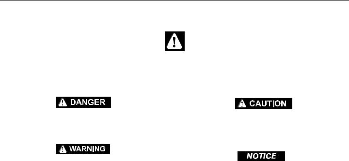
SAFETY ALERT SYMBOLS AND SAFETY SIGNAL WORDS
This is the Safety Alert Symbol. It is used to alert you to the potential personal injury hazards. Obey all safety messages that follow this symbol to avoid possible injury or death
INDICATES AN IMMINENTLY HAZARDOUS SITUATION. IF NOT AVOIDED, WILL RESULT IN SERIOUS INJURY OR DEATH. THIS DECAL WILL HAVE A RED BACKGROUND.
INDICATES A POTENTIALIT Y HAZARDOUS SITUATION. IF NOT AVOIDED, COULD RESULT IN SERIOUS INJURY OR DEATH. THIS DECAL WILL HAVE AN ORANGE BACKGROUND.
INDICATES A POTENTIALIT Y HAZARDOUS SITUATION. IF NOT AVOIDED, MAY RESULT IN MINOR OR MODERATE INJURY. IT MAY ALSO ALERT AGAINST UNSAFE PRACTICES. THIS DECAL WILL HAVE A YELLOW BACKGROUND.
INDICATES INFORMATION OR A COMPANY POLICY THAT RELATES DIRECTLY OR INDIRECTLY TO THE SAFETY OF PERSONNEL OR PROTECTION OF PROPERTY.
b |
– JLG Lift – |
3121165 |

FOREWORD
THIS PRODUCT MUST COMPLY WITH ALL SAFETY RELATED BULLETINS. CONTACT JLG INDUSTRIES, INC. OR THE LOCAL AUTHORIZED JLG REPRESENTATIVE FOR INFORMATION REGARDING SAFETYRELATED BULLETINS WHICH MAY HAVE BEEN ISSUED FOR THIS PRODUCT.
JLG INDUSTRIES, INC. SENDS SAFETY RELATED BULLETINS TO THE OWNER OF RECORD OF THIS MACHINE. CONTACT JLG INDUSTRIES, INC. TO ENSURE THAT THE CURRENT OWNER RECORDS ARE UPDATED AND ACCURATE.
JLG INDUSTRIES, INC. MUST BE NOTIFIED IMMEDIATELY IN ALL INSTANCES WHERE JLG PRODUCTS HAVE BEEN INVOLVED IN AN ACCIDENT INVOLVING BODILY INJURY OR DEATH OF PERSONNEL OR WHEN SUBSTANTIAL DAMAGE HAS OCCURRED TO PERSONAL PROPERTY OR THE JLG PRODUCT.
For:
•Accident Reporting
•Product Safety Publications
•Current Owner Updates
•Questions Regarding Product Safety
•Standards and Regulations Compliance Information
•Questions Regarding Special Product Applications
•Questions Regarding Product Modifications
Contact:
Product Safety and Reliability Department
JLG Industries, Inc.
13224 Fountainhead Plaza
Hagerstown, MD 21742
or Your Local JLG Office
(See addresses on manual rear cover)
In USA:
Toll Free: 877-JLG-SAFE (877-554-7233)
Outside USA:
Phone: 240-420-2661
E-mail: ProductSafety@JLG.com
3121165 |
– JLG Lift – |
c |

FOREWORD
REVISION LOG
Original Issue. . . . . . . . . . . . . . . . . . .March 31, 2003
Revised . . . . . . . . . . . . . . . . . . . . . . . .April 30, 2003
Revised . . . . . . . . . . . . . . . . . . . . . . . .May 21, 2003
Revised . . . . . . . . . . . . . . . . . . . . . . . .June 13, 2003
Revised . . . . . . . . . . . . . . . . . . . . . . . .June 25, 2003
Revised . . . . . . . . . . . . . . . . . . . . . . . .August 26, 2003
Revised . . . . . . . . . . . . . . . . . . . . . . . .December 3, 2003
Revised . . . . . . . . . . . . . . . . . . . . . . . .March 3, 2004
Revised . . . . . . . . . . . . . . . . . . . . . . . .September 17, 2004
Revised . . . . . . . . . . . . . . . . . . . . . . . .June 15, 2005
Revised . . . . . . . . . . . . . . . . . . . . . . . .September 12, 2005
Revised . . . . . . . . . . . . . . . . . . . . . . . .October 21, 2005
Revised . . . . . . . . . . . . . . . . . . . . . . . .February 16, 2006
Revised . . . . . . . . . . . . . . . . . . . . . . . .April 11, 2007
Revised . . . . . . . . . . . . . . . . . . . . . . . .February 19, 2010
Revised . . . . . . . . . . . . . . . . . . . . . . . .January 18, 2011
Revised . . . . . . . . . . . . . . . . . . . . . . . .July 13, 2011
Revised . . . . . . . . . . . . . . . . . . . . . . . .September 28, 2012
Revised . . . . . . . . . . . . . . . . . . . . . . . .May 1, 2013
d |
– JLG Lift – |
3121165 |

TABLE OF CONTENTS
SECTION - PARAGRAPH, SUBJECT |
PAGE |
SECTION - 1 - SAFETY PRECAUTIONS
1.1 GENERAL. . . . . . . . . . . . . . . . . . . . . . . . . . . . . . . . . . . . . . . 1-1
1.2 PRE-OPERATION. . . . . . . . . . . . . . . . . . . . . . . . . . . . . . . . 1-1
Operator Training and Knowledge . . . . . . . . . . . 1-1
Workplace Inspection . . . . . . . . . . . . . . . . . . . . . . . 1-2
Machine Inspection . . . . . . . . . . . . . . . . . . . . . . . . . 1-3
1.3 OPERATION . . . . . . . . . . . . . . . . . . . . . . . . . . . . . . . . . . . . 1-3
General . . . . . . . . . . . . . . . . . . . . . . . . . . . . . . . . . . . . . 1-3
Trip and Fall Hazards . . . . . . . . . . . . . . . . . . . . . . . . 1-4
Electrocution Hazards . . . . . . . . . . . . . . . . . . . . . . . 1-5
Tipping Hazards. . . . . . . . . . . . . . . . . . . . . . . . . . . . . 1-7
Crushing and Collision Hazards . . . . . . . . . . . . . . 1-8
1.4 TOWING, LIFTING, AND HAULING . . . . . . . . . . . . . . . 1-9
1.5 MAINTENANCE . . . . . . . . . . . . . . . . . . . . . . . . . . . . . . . .1-10
General . . . . . . . . . . . . . . . . . . . . . . . . . . . . . . . . . . . . 1-10
Maintenance Hazards . . . . . . . . . . . . . . . . . . . . . . 1-10
Battery Hazards . . . . . . . . . . . . . . . . . . . . . . . . . . . . 1-11
SECTION - 2 - USER RESPONSIBILITIES, MACHINE PREPARA-
TION & INSPECTION
2.1 PERSONNEL TRAINING. . . . . . . . . . . . . . . . . . . . . . . . . . 2-1
Operator Training . . . . . . . . . . . . . . . . . . . . . . . . . . . 2-1
Training Supervision . . . . . . . . . . . . . . . . . . . . . . . . 2-1
Operator Responsibility . . . . . . . . . . . . . . . . . . . . . 2-1
SECTION - PARAGRAPH, SUBJECT |
PAGE |
2.2PREPARATION, INSPECTION, AND
MAINTENANCE . . . . . . . . . . . . . . . . . . . . . . . . . . . . . . . . .2-2
Pre-Start Inspection. . . . . . . . . . . . . . . . . . . . . . . . . . 2-4
Function Check . . . . . . . . . . . . . . . . . . . . . . . . . . . . . . 2-5
General . . . . . . . . . . . . . . . . . . . . . . . . . . . . . . . . . . . . . 2-8
SECTION - 3 - USER RESPONSIBILITIES AND MACHINE CONTROLS
3.1 GENERAL . . . . . . . . . . . . . . . . . . . . . . . . . . . . . . . . . . . . . . .3-1 3.2 PERSONNEL TRAINING . . . . . . . . . . . . . . . . . . . . . . . . . .3-1 Operator Training . . . . . . . . . . . . . . . . . . . . . . . . . . . 3-1 Training Supervision . . . . . . . . . . . . . . . . . . . . . . . . . 3-2 Operator Responsibility . . . . . . . . . . . . . . . . . . . . . . 3-2
3.3OPERATING CHARACTERISTICS AND
LIMITATIONS . . . . . . . . . . . . . . . . . . . . . . . . . . . . . . . . . . .3-2
General . . . . . . . . . . . . . . . . . . . . . . . . . . . . . . . . . . . . . 3-2
Placards . . . . . . . . . . . . . . . . . . . . . . . . . . . . . . . . . . . . . 3-2
Capacities . . . . . . . . . . . . . . . . . . . . . . . . . . . . . . . . . . . 3-2
Stability . . . . . . . . . . . . . . . . . . . . . . . . . . . . . . . . . . . . . 3-3
3.4 CONTROLS AND INDICATORS . . . . . . . . . . . . . . . . . . .3-3
Ground Control Station . . . . . . . . . . . . . . . . . . . . . . 3-3
3.5 PLATFORM CONTROL STATION . . . . . . . . . . . . . . . . .3-5
3.6 MDI (MULTIFUNCTION DIGITAL INDICATOR) . . . . .3-9
MDI Description . . . . . . . . . . . . . . . . . . . . . . . . . . . . 3-10
3121165 |
– JLG Lift – |
i |

TABLE OF CONTENTS
SECTION - PARAGRAPH, SUBJECT |
PAGE |
SECTION - 4 - MACHINE OPERATION
4.1 DESCRIPTION . . . . . . . . . . . . . . . . . . . . . . . . . . . . . . . . . . .4-1 4.2 OPERATION . . . . . . . . . . . . . . . . . . . . . . . . . . . . . . . . . . . .4-1 Platform/Ground Select Switch . . . . . . . . . . . . . . 4-1 Emergency Stop Switch. . . . . . . . . . . . . . . . . . . . . . 4-1 4.3 RAISING AND LOWERING. . . . . . . . . . . . . . . . . . . . . . . .4-2 Raising . . . . . . . . . . . . . . . . . . . . . . . . . . . . . . . . . . . . . . 4-2 Lowering. . . . . . . . . . . . . . . . . . . . . . . . . . . . . . . . . . . . 4-2 Arm Guards (If equipped) . . . . . . . . . . . . . . . . . . . . 4-3 Platform Extension . . . . . . . . . . . . . . . . . . . . . . . . . . 4-3 Fold-Down Rails . . . . . . . . . . . . . . . . . . . . . . . . . . . . . 4-3
4.4 STEERING. . . . . . . . . . . . . . . . . . . . . . . . . . . . . . . . . . . . . . .4-4 4.5 DRIVING . . . . . . . . . . . . . . . . . . . . . . . . . . . . . . . . . . . . . . . .4-4 Driving Forward . . . . . . . . . . . . . . . . . . . . . . . . . . . . . 4-5 Driving in Reverse . . . . . . . . . . . . . . . . . . . . . . . . . . . 4-5 4.6 PARKING AND STOWING . . . . . . . . . . . . . . . . . . . . . . . .4-7
4.7 BATTERY CHARGING . . . . . . . . . . . . . . . . . . . . . . . . . . . .4-8 Operation . . . . . . . . . . . . . . . . . . . . . . . . . . . . . . . . . . . 4-8 Battery Charger Fault Codes . . . . . . . . . . . . . . . . . 4-9 4.8 PLATFORM LOADING . . . . . . . . . . . . . . . . . . . . . . . . . 4-10
4.9 SAFETY PROP . . . . . . . . . . . . . . . . . . . . . . . . . . . . . . . . . 4-10 4.10 TIE DOWN/LIFT LUGS . . . . . . . . . . . . . . . . . . . . . . . . . 4-11 4.11 LIFTING. . . . . . . . . . . . . . . . . . . . . . . . . . . . . . . . . . . . . . . 4-11 4.12 TOWING . . . . . . . . . . . . . . . . . . . . . . . . . . . . . . . . . . . . . . 4-13 Remote Electric Brake Release. . . . . . . . . . . . . . . 4-13
SECTION - PARAGRAPH, SUBJECT |
PAGE |
Push Button Electric Brake Release. . . . . . . . . . 4-13
Mechanical Brake Release . . . . . . . . . . . . . . . . . . 4-14
Mechanical Brake Release . . . . . . . . . . . . . . . . . . 4-15
Mechanical Brake Release . . . . . . . . . . . . . . . . . . 4-16
4.13 DIAGNOSTIC TROUBLE CODES (DTC). . . . . . . . . . . 4-18
Introduction . . . . . . . . . . . . . . . . . . . . . . . . . . . . . . . 4-18
4.14 DTC CHECK TABLES - CONTROL MODULE . . . . . . 4-19
0-0 Help Comments. . . . . . . . . . . . . . . . . . . . . . . . 4-19
2-1 Power-Up . . . . . . . . . . . . . . . . . . . . . . . . . . . . . . 4-21
2-2 Platform Controls . . . . . . . . . . . . . . . . . . . . . . 4-21
2-3 Ground Controls . . . . . . . . . . . . . . . . . . . . . . . 4-23
2-5 Function Prevented . . . . . . . . . . . . . . . . . . . . 4-23
3-1 Line Contactor Open Circuit . . . . . . . . . . . . 4-25
3-2 Line Contactor Short Circuit . . . . . . . . . . . . 4-26
3-3 Ground Output Driver . . . . . . . . . . . . . . . . . . 4-26
4-2 Thermal Limit (SOA) . . . . . . . . . . . . . . . . . . . . 4-29
4-4 Battery Supply . . . . . . . . . . . . . . . . . . . . . . . . . 4-29
6-6 Communication. . . . . . . . . . . . . . . . . . . . . . . . 4-30
6-7 Accessory . . . . . . . . . . . . . . . . . . . . . . . . . . . . . . 4-31
7-7 Electric Motor . . . . . . . . . . . . . . . . . . . . . . . . . . 4-31
8-1 Tilt Sensor . . . . . . . . . . . . . . . . . . . . . . . . . . . . . 4-32
8-2 Platform Load Sense . . . . . . . . . . . . . . . . . . . 4-33
9-9 Hardware . . . . . . . . . . . . . . . . . . . . . . . . . . . . . . 4-33
ii |
– JLG Lift – |
3121165 |

TABLE OF CONTENTS
SECTION - PARAGRAPH, SUBJECT |
PAGE |
SECTION - 5 - EMERGENCY PROCEDURES
5.1 GENERAL. . . . . . . . . . . . . . . . . . . . . . . . . . . . . . . . . . . . . . . 5-1 Emergency Stop Switch . . . . . . . . . . . . . . . . . . . . . 5-1 Manual Descent . . . . . . . . . . . . . . . . . . . . . . . . . . . . . 5-1 5.2 EMERGENCY OPERATION . . . . . . . . . . . . . . . . . . . . . . . 5-2 Operator Unable to Control Machine. . . . . . . . . 5-2 Platform Caught Overhead . . . . . . . . . . . . . . . . . . 5-3 Righting of Tipped Machine . . . . . . . . . . . . . . . . . 5-3 Post-Incident Inspection. . . . . . . . . . . . . . . . . . . . . 5-3
5.3 INCIDENT NOTIFICATION . . . . . . . . . . . . . . . . . . . . . . . 5-3
SECTION - 6 - GENERAL SPECIFICATIONS AND
OPERATOR MAINTENANCE
6.1 INTRODUCTION . . . . . . . . . . . . . . . . . . . . . . . . . . . . . . . . 6-1
6.2 OPERATING SPECIFICATIONS . . . . . . . . . . . . . . . . . . . 6-2
Dimensional Data . . . . . . . . . . . . . . . . . . . . . . . . . . . 6-6
Motors . . . . . . . . . . . . . . . . . . . . . . . . . . . . . . . . . . . . . . 6-7
Batteries . . . . . . . . . . . . . . . . . . . . . . . . . . . . . . . . . . . . 6-7
Capacities . . . . . . . . . . . . . . . . . . . . . . . . . . . . . . . . . . 6-8
Tires . . . . . . . . . . . . . . . . . . . . . . . . . . . . . . . . . . . . . . . . 6-8
6.3 CRITICAL STABILITY WEIGHTS . . . . . . . . . . . . . . . . . . . 6-9
Lubrication . . . . . . . . . . . . . . . . . . . . . . . . . . . . . . . . 6-10
6.4 OPERATOR MAINTENANCE . . . . . . . . . . . . . . . . . . . .6-11
Oil Check Procedure (1) . . . . . . . . . . . . . . . . . . . . 6-12
Lower (2) & Upper Slide Pads (3) . . . . . . . . . . . . 6-13
SECTION - PARAGRAPH, SUBJECT |
PAGE |
6.5 TIRES AND WHEELS . . . . . . . . . . . . . . . . . . . . . . . . . . . 6-15
Tire Wear and Damage. . . . . . . . . . . . . . . . . . . . . . 6-15
Wheel and Tire Replacement. . . . . . . . . . . . . . . . 6-15
Wheel Installation . . . . . . . . . . . . . . . . . . . . . . . . . . 6-15
6.6 SUPPLEMENTAL INFORMATION . . . . . . . . . . . . . . . 6-16
SECTION - 7 - INSPECTION AND REPAIR LOG
3121165 |
– JLG Lift – |
iii |

TABLE OF CONTENTS
SECTION - PARAGRAPH, SUBJECT |
PAGE |
LIST OF FIGURES
2-1. Daily Walk-Around Inspection - Sht. 1 of 3 . . . . . . .2-7 2-2. Daily Walk-Around Inspection - Sht. 2 of 3 . . . . . . .2-8 2-3. Daily Walk-Around Inspection - Sht. 3 of 3 . . . . . . .2-9 2-4. Switch Location - 1 of 2 . . . . . . . . . . . . . . . . . . . . . . . 2-10 2-5. Switch Location - 2 of 2 . . . . . . . . . . . . . . . . . . . . . . . 2-11 3-1. Ground Control Station . . . . . . . . . . . . . . . . . . . . . . . . .3-4 3-2. Battery Charger Status . . . . . . . . . . . . . . . . . . . . . . . . . .3-4 3-3. Platform Control Station . . . . . . . . . . . . . . . . . . . . . . . .3-5 3-4. MDI Indicator - Location and Description . . . . . . . .3-9 3-4. Decal Location - 1930ESSht. 1 of 2 . . . . . . . . . . . 3-11 3-5. Decal Location - 1930ES - Sht. 2 of 2 . . . . . . . . . . . 3-12 3-6. Decal Location - 2030ES & 2630ES - Sht. 1 of 2 . 3-13 3-7. Decal Location - 2030ES & 2630ES - Sht. 2 of 2 . 3-14 3-8. Decal Location - 2646ES & 3246ES - Sht. 1 of 2 . 3-15 3-9. Decal Location - 2646ES & 3246ES - Sht. 2 of 2 . 3-16 4-1. Grade and Sideslope. . . . . . . . . . . . . . . . . . . . . . . . . . . .4-6 4-2. Securing Control Station to Platform . . . . . . . . . . . .4-7 4-3. Lifting and Tie Down Diagram . . . . . . . . . . . . . . . . 4-12 4-4. Manual Disengage. . . . . . . . . . . . . . . . . . . . . . . . . . . . 4-14 4-5. Manual Disengage. . . . . . . . . . . . . . . . . . . . . . . . . . . . 4-15 4-6. Manual Disengage. . . . . . . . . . . . . . . . . . . . . . . . . . . . 4-16 4-7. Lifting and Tie Down Chart. . . . . . . . . . . . . . . . . . . . 4-17 6-1. Lubrication Diagram . . . . . . . . . . . . . . . . . . . . . . . . . . 6-11 6-2. Lower Slide Pad Channel. . . . . . . . . . . . . . . . . . . . . . 6-13
SECTION - PARAGRAPH, SUBJECT |
PAGE |
6-3. Upper Slide Pad Channel . . . . . . . . . . . . . . . . . . . . . . 6-14
LIST OF TABLES
1-1 Minimum Approach Distances (M.A.D.) . . . . . . . . . 1-6 2-1 Inspection and Maintenance Table . . . . . . . . . . . . . 2-3 2-2 Tilt vs. Height . . . . . . . . . . . . . . . . . . . . . . . . . . . . . . . . . . 2-6 2-3 High Drive Speed Cutout Height. . . . . . . . . . . . . . . . 2-6 3-1 Decal Location Legend . . . . . . . . . . . . . . . . . . . . . . . . 3-17 4-1 Battery Charger Flash Codes . . . . . . . . . . . . . . . . . . . . 4-9 6-1 Operating Specifications . . . . . . . . . . . . . . . . . . . . . . . 6-2 6-2 Platform Capacities . . . . . . . . . . . . . . . . . . . . . . . . . . . . 6-5 6-3 Dimensions . . . . . . . . . . . . . . . . . . . . . . . . . . . . . . . . . . . . 6-6 6-4 Battery Specifications . . . . . . . . . . . . . . . . . . . . . . . . . . 6-7 6-5 Capacities. . . . . . . . . . . . . . . . . . . . . . . . . . . . . . . . . . . . . . 6-8 6-6 Tire Specifications. . . . . . . . . . . . . . . . . . . . . . . . . . . . . . 6-8 6-7 Critical Stability Weights. . . . . . . . . . . . . . . . . . . . . . . . 6-9 6-8 Hydraulic Oil Specifications. . . . . . . . . . . . . . . . . . . . 6-10 6-9 Wheel Torque Chart . . . . . . . . . . . . . . . . . . . . . . . . . . . 6-16 7-1 Inspection and Repair Log . . . . . . . . . . . . . . . . . . . . . . 7-1
iv |
– JLG Lift – |
3121165 |
SECTION 1 - SAFETY PRECAUTIONS
SECTION 1. SAFETY PRECAUTIONS
1.1GENERAL
This section outlines the necessary precautions for proper and safe machine usage and maintenance. In order to promote proper machine usage, it is mandatory that a daily routine is established based on the content of this manual. A maintenance program, using the information provided in this manual and the Service and Maintenance Manual, must also be established by a qualified person and must be followed to ensure that the machine is safe to operate.
The owner/user/operator/lessor/lessee of the machine should not accept operating responsibility until this manual has been read, training is accomplished, and operation of the machine has been completed under the supervision of an experienced and qualified operator.
These sections contain the responsibilities of the owner, user, operator, lessor, and lessee concerning safety, training, inspection, maintenance, application, and operation.If there are any questions with regard to safety, training, inspection, maintenance, application, and operation, please contact JLG Industries, Inc. (“JLG”).
FAILURE TO COMPLY WITH THE SAFETY PRECAUTIONS LISTED IN THIS MANUAL COULD RESULT IN MACHINE DAMAGE, PROPERTY DAMAGE, PERSONAL INJURY OR DEATH.
3121165 |
– JLG Lift – |
1-1 |

SECTION 1 - SAFETY PRECAUTIONS
1.2PRE-OPERATION
Operator Training and Knowledge
•The Operators and Safety Manual must be read in its entirety before operating the machine. For clarification, questions, or additional information regarding any portions of this manual, contact JLG Industries, Inc.
•An operator must not accept operating responsibilities until adequate training has been given by competent and authorized persons.
•Allow only those authorized and qualified personnel to operate the machine who have demonstrated that they understand the safe and proper operation and maintenance of the unit.
•Read, understand, and obey all DANGERS, WARNINGS, CAUTIONS, and operating instructions on the machine and in this manual.
•Ensure that the machine is to be used in a manner which is within the scope of its intended application as determined by JLG.
•All operating personnel must be familiar with the emergency controls and emergency operation of the machine as specified in this manual.
•Read, understand, and obey all applicable employer, local, and governmental regulations as they pertain to your utilization and application of the machine.
Workplace Inspection
•Precautions to avoid all hazards in the work area must be taken by the user before operation of the machine.
•Do not operate or raise the platform from a position on trucks, trailers, railway cars, floating vessels, scaffolds or other equipment unless the application is approved in writing by JLG.
•Before operation, check work area for overhead hazards such as electric lines, bridge cranes, and other potential overhead obstructions.
•Check floor surfaces for holes, bumps, drop-offs, obstructions, debris, concealed holes, and other potential hazards.
1-2 |
– JLG Lift – |
3121165 |

SECTION 1 - SAFETY PRECAUTIONS
•Check the work area for hazardous locations. Do not operate the machine in hazardous environments unless approved for that purpose by JLG.
•Ensure that the ground conditions are adequate to support the maximum tire load indicated on the tire load decals located on the chassis adjacent to each wheel.
•Do not operate the machine when wind conditions exceed 28 mph (12.5 m/s).
•This machine can be operated in nominal ambient temperatures of 0oF to 104oF (-20oC to 40oC). Consult JLG to optimize operation outside of this temperature range.
Machine Inspection
•Do not operate this machine until the inspections and functional checks have been performed as specified in Section 2 of this manual.
•Do not operate this machine until it has been serviced and maintained according to the maintenance and inspection requirements as specified in the machine’s Service and Maintenance Manual.
•Ensure all safety devices are operating properly. Modification of these devices is a safety violation.
MODIFICATION OR ALTERATION OF AN AERIAL WORK PLATFORM SHALL BE MADE ONLY WITH PRIOR WRITTEN PERMISSION FROM THE MANUFACTURER.
•Do not operate any machine on which the safety or instruction placards or decals are missing or illegible.
•Check the machine for modifications to original components. Ensure that any modifications have been approved by JLG.
•Avoid accumulation of debris on platform deck. Keep mud, oil, grease, and other slippery substances from footwear and platform deck.
1.3OPERATION
General
•Do not use the machine for any purpose other than positioning personnel, their tools, and equipment.
•Before operation, the user must be familiar with the machine capabilities and operating characteristics of all functions.
•Never operate a malfunctioning machine. If a malfunction occurs, shut down the machine. Remove the unit from service and notify the proper authorities.
3121165 |
– JLG Lift – |
1-3 |
SECTION 1 - SAFETY PRECAUTIONS
•Do not remove, modify, or disable any safety devices.
•Never slam a control switch or lever through neutral to an opposite direction. Always return switch to neutral and stop before moving the switch to the next function. Operate controls with slow and even pressure.
•Do not allow personnel to tamper with or operate the machine from the ground with personnel in the platform, except in an emergency.
•Do not carry materials directly on platform railing unless approved by JLG.
•When two or more persons are in the platform, the operator shall be responsible for all machine operations.
•Always ensure that power tools are properly stowed and never left hanging by their cord from the platform work area.
•Do not assist a stuck or disabled machine by pushing or pulling except by pulling at the chassis tie-down lugs.
•Stow scissor arm assembly and shut off all power before leaving machine.
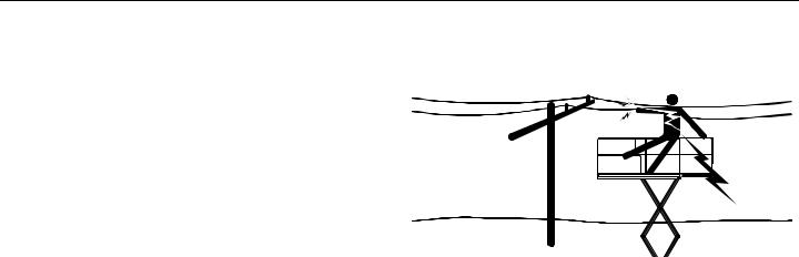
Electrocution Hazards
•This machine is not insulated and does not provide protection from contact or proximity to electrical current.
•Maintain safe clearance from electrical lines, apparatus, or any energized (exposed or insulated) parts in accordance with the Minimum Approach Distance (M.A.D.) as specified in Table 1-1 on page 1-5
•Allow for machine movement and electrical line swaying.
•Maintain a clearance of at least 10 ft (3 m) between any part of the machine and its occupants, their tools, and their equipment from any electrical line or apparatus carrying up to 50,000 volts. One foot additional clearance is required for every additional 30,000 volts or less.
1-4 |
– JLG Lift – |
3121165 |

SECTION 1 - SAFETY PRECAUTIONS
Table 1-1.Minimum Approach Distances (M.A.D.)
Voltage Range |
MINIMUM APPROACH DISTANCE |
(Phase to Phase) |
in Feet (Meters) |
|
|
0to 50KV |
10 (3) |
|
|
Over50 KV to 200 KV |
15 (5) |
|
|
Over 200 KV to 350 KV |
20 (6) |
|
|
Over 350 KV to 500 KV |
25 (8) |
|
|
Over 500 KV to 750 KV |
35 (11) |
|
|
Over 750 KV to 1000 KV |
45 (14) |
|
|
NOTE: This requirement shall apply except where employer, local or governmental regulations are more stringent.
•The minimum approach distance may be reduced if insulating barriers are installed to prevent contact, and the barriers are rated for the voltage of the line being guarded. These barriers shall not be part of (or attached to) the machine. The minimum approach distance shall be reduced to a distance within the designed working dimensions of the insulating barrier. This determination shall be made by a qualified person in accordance with the employer, local, or governmental requirements for work practices near energized equipment.
DO NOT MANEUVER MACHINE OR PERSONNEL INSIDE PROHIBITED ZONE (M.A.D.). ASSUME ALL ELECTRICAL PARTS AND WIRING ARE ENERGIZED UNLESS KNOWN OTHERWISE.
3121165 |
– JLG Lift – |
1-5 |
SECTION 1 - SAFETY PRECAUTIONS
Trip and Fall Hazards |
. |
|
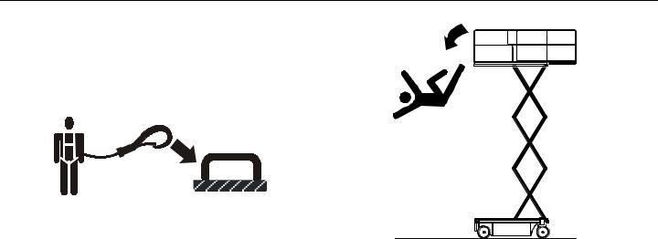
•JLG Industries, Inc. recommends that all persons in the platform wear a full body harness with a lanyard attached to an authorized lanyard anchorage point while operating this machine. For further information regarding fall protection requirements on JLG products, contact JLG Industries, Inc.
•Prior to operation, ensure all gates and rails are fastened and secured in their proper position. Identify the designated lanyard anchorage point(s) at the platform and securely attach the lanyard. Attach only one (1) lanyard per lanyard anchorage point.
•Keep both feet firmly positioned on the platform floor at all times. Never position ladders, boxes, steps, planks, or similar items on unit to provide additional reach for any purpose.
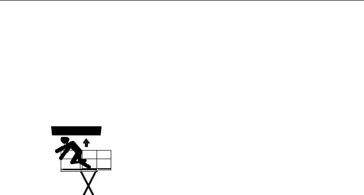
•Never use the scissor arm assembly to gain access to or leave the platform.
•Use extreme caution when entering or leaving platform. Ensure that the scissor arm assembly is fully lowered. Face the machine when entering or leaving the platform. Always maintain “three point contact” with the machine, using two hands and one foot or two feet and one hand at all times during entry and exit.
•Keep oil, mud, and slippery substances cleaned from footwear and the platform floor.
1-6 |
– JLG Lift – |
3121165 |

SECTION 1 - SAFETY PRECAUTIONS
Tipping Hazards
•Ensure that the ground conditions are adequate to support the maximum tire load indicated on the tire load decals located on the chassis adjacent to each wheel. Do not travel on unsupported surfaces.
•The user should be familiar with the driving surface before driving. Do not exceed the allowable sideslope and grade while driving.
.
•Do not elevate platform or drive with platform elevated while on or near a sloping, uneven, or soft surface. Ensure machine is positioned on a firm, level and smooth surface before elevating platform or driving with the platform in the elevated position.
•Before driving on floors, bridges, trucks, and other surfaces, check allowable capacity of the surfaces.
•Never exceed the maximum work load as specified on the platform. Keep all loads within the confines of the platform, unless authorized by JLG.
•Keep the chassis of the machine a minimum of 0.6 m (2 ft) from holes, bumps, drop-offs, obstructions, debris, concealed holes, and other potential hazards at the ground level.
•Never attempt to use the machine as a crane. Do not tie-off machine to any adjacent structure. Never attach wire, cable, or any similar items to platform.
•Do not cover the platform sides or carry large surface-area items in the platform when operating outdoors. The addition of such items increases the exposed wind area of the machine.
•Do not increase the platform size with unauthorized deck extensions or attachments.
3121165 |
– JLG Lift – |
1-7 |
SECTION 1 - SAFETY PRECAUTIONS
•If scissor arm assembly or platform is caught so that one or more wheels are off the ground, all persons must be removed before attempting to free the machine. Use cranes, forklift trucks, or other appropriate equipment to stabilize machine and remove personnel.
Crushing and Collision Hazards
•Approved head gear must be worn by all operating and ground personnel.
•Keep hands and limbs out of the scissor arm assembly during operation.
•Watch for obstructions around machine and overhead when driving. Check clearances above, on sides, and bottom of platform when lifting or lowering platform.
•During operation, keep all body parts inside platform railing.
•Always post a lookout when driving in areas where vision is obstructed.
•Keep non-operating personnel at least 1.8 m (6 ft) away from machine during all driving operations.
•Under all travel conditions, the operator must limit travel speed according to conditions of ground surface, congestion, visibility, slope, location of personnel, and other factors causing hazards of collision or injury to personnel.
•Be aware of stopping distances in all drive speeds. When driving in high speed, switch to low speed before stopping. Travel grades in low speed only.
•Do not use high speed drive in restricted or close quarters or when driving in reverse.
•Exercise extreme caution at all times to prevent obstacles from striking or interfering with operating controls and persons in the platform.
•Ensure that operators of other overhead and floor level machines are aware of the aerial work platform’s presence. Disconnect power to overhead cranes. Barricade floor area if necessary.
•Avoid operating over ground personnel. Warn personnel not to work, stand, or walk under a raised platform. Position barricades on floor as necessary.
1-8 |
– JLG Lift – |
3121165 |

SECTION 1 - SAFETY PRECAUTIONS
1.4 TOWING, LIFTING, AND HAULING |
1.5 MAINTENANCE |
•Never allow personnel in platform while towing, lifting, or hauling.
•This machine should not be towed, except in the event of emergency, malfunction, power failure, or loading/unloading. Refer to emergency towing procedures.
•Ensure platform is fully retracted and completely empty of tools prior to towing, lifting or hauling.
•When lifting machine with a forklift, position forks only at designated areas of the machine. Lift with a forklift of adequate capacity.
•Refer to Section 4 for lifting information.
General
This section contains general safety precautions which must be observed during maintenance of this machine. Additional precautions to be observed during machine maintenance are inserted at the appropriate points in this manual and in the Service and Maintenance Manual. It is of utmost importance that maintenance personnel pay strict attention to these precautions to avoid possible injury to personnel or damage to the machine or property. A maintenance program must be established by a qualified person and must be followed to ensure that the machine is safe.
Maintenance Hazards
•Shut off power to all controls and ensure that all operating systems are secured from inadvertent motion prior to performing any adjustments or repairs.
•Never work under an elevated platform until it has been fully lowered to the full down position, if possible, or otherwise supported and restrained from movement with appropriate safety props, blocking, or overhead supports.
•Always relieve hydraulic pressure from all hydraulic circuits before loosening or removing hydraulic components.
•Always disconnect batteries when servicing electrical components or when performing welding on the machine.
3121165 |
– JLG Lift – |
1-9 |

SECTION 1 - SAFETY PRECAUTIONS
•Shut down the engine (if equipped) while fuel tanks are being filled.
•Ensure replacement parts or components are identical or equivalent to original parts or components.
•Never attempt to move heavy parts without the aid of a mechanical device. Do not allow heavy objects to rest in an unstable position. Ensure adequate support is provided when raising components of the machine.
•Remove all rings, watches, and jewelry when performing any maintenance. Do not wear loose fitting clothing or long hair unrestrained which may become caught or entangled in equipment.
•Use only clean approved non-flammable cleaning solvents.
•Never alter, remove, or substitute any items such as counterweights, tires, batteries, platforms or other items that may reduce or affect the overall weight or stability of the machine.
•Reference the Service and Maintenance Manual for the weights of critical stability items.
MODIFICATION OR ALTERATION OF AN AERIAL WORK PLATFORM SHALL BE MADE ONLY WITH PRIOR WRITTEN PERMISSION FROM THE MANUFACTURER.
Battery Hazards
•Always disconnect batteries when servicing electrical components or when performing welding on the machine.
•Do not allow smoking, open flame, or sparks near battery during charging or servicing.
•Do not contact tools or other metal objects across the battery terminals.
•Always wear hand, eye, and face protection when servicing batteries. Ensure that battery acid does not come in contact with skin or clothing.
BATTERY FLUID IS HIGHLY CORROSIVE. AVOID CONTACT WITH SKIN AND CLOTHING AT ALL TIMES. IMMEDIATELY RINSE ANY CONTACTED AREA WITH CLEAN WATER AND SEEK MEDICAL ATTENTION.
•Charge batteries only in a well ventilated area.
•Avoid overfilling the battery fluid level. Add distilled water to batteries only after the batteries are fully charged.
1-10 |
– JLG Lift – |
3121165 |
SECTION 2 - USER RESPONSIBILITIES, MACHINE PREPARATION & INSPECTION
SECTION 2. USER RESPONSIBILITIES, MACHINE PREPARATION & INSPECTION
2.1PERSONNEL TRAINING
The aerial platform is a personnel handling device; so it is necessary that it be operated and maintained only by trained personnel.
Persons under the influence of drugs or alcohol or who are subject to seizures, dizziness or loss of physical control must not operate this machine.
Operator Training
Operator training must cover:
1.Use and limitations of the controls in the platform and at the ground, emergency controls and safety systems.
2.Control labels, instructions, and warnings on the machine.
3.Rules of the employer and government regulations.
4.Use of approved fall protection device.
5.Enough knowledge of the mechanical operation of the machine to recognize a malfunction or potential malfunction.
6.The safest means to operate the machine where overhead obstructions, other moving equipment, and obstacles, depressions, holes, drop-offs.
7.Means to avoid the hazards of unprotected electrical conductors.
8.Specific job requirements or machine application.
Training Supervision
Training must be done under the supervision of a qualified person in an open area free of obstructions until the trainee has developed the ability to safely control and operate the machine.
Operator Responsibility
The operator must be instructed that he/she has the responsibility and authority to shut down the machine in case of a malfunction or other unsafe condition of either the machine or the job site.
3121165 |
– JLG Lift – |
2-1 |

SECTION 2 - USER RESPONSIBILITIES, MACHINE PREPARATION & INSPECTION
2.2PREPARATION, INSPECTION, AND MAINTENANCE
The table below covers the periodic machine inspections and maintenance recommended by JLG Industries, Inc. Consult local regulations for further requirements for aerial work platforms. The frequency of inspections and maintenance must be increased as necessary when the machine is used in a harsh or hostile environment, if the machine is used with increased frequency, or if the machine is used in a severe manner.
Table 2-1. Inspection and Maintenance Table
Type |
Frequency |
Primary |
Service |
Reference |
|
Responsibility |
Qualification |
||||
|
|
|
|||
Pre-Start Inspection |
Beforeusingeach day;or |
UserorOperator |
UserorOperator |
Operation andSafetyManual |
|
|
wheneverthere’san Operatorchange. |
|
|
|
|
Pre-DeliveryInspection |
Beforeeach sale,lease,or rental delivery. |
Owner,Dealer,orUser |
QualifiedJLG |
ServiceandMaintenance Manual and |
|
(seenotebelow) |
|
|
Mechanic |
applicableJLG inspectionform |
|
FrequentInspection |
In servicefor 3months or 150 hours,whichevercomes |
Owner,Dealer,orUser |
QualifiedJLG |
ServiceandMaintenance Manual and |
|
|
first;orOutof service fora periodof morethan 3 |
|
Mechanic |
applicableJLG inspectionform |
|
|
months;orPurchased used. |
|
|
|
|
AnnualMachine |
Annually,no laterthan13 monthsfrom thedateof |
Owner,Dealer,orUser |
FactoryTrained |
ServiceandMaintenance Manual and |
|
Inspection |
prior inspection. |
|
ServiceTechnician |
applicableJLG inspectionform |
|
(seenotebelow) |
|
|
(Recommended) |
|
|
PreventativeMaintenance |
Atintervalsas specifiedin the Serviceand Mainte- |
Owner,Dealer,orUser |
QualifiedJLG |
Service andMaintenance Manual |
|
|
nance Manual. |
|
Mechanic |
|
NOTE: Inspection forms are available from JLG. Use the Service and Maintenance Manual to perform inspections.
NOTICE
JLG INDUSTRIES, INC. RECOGNIZES A FACTORY-TRAINED SERVICE TECHNICIAN AS A PERSON WHO HAS SUCCESSFULLY COMPLETED THE JLG SERVICE TRAINING SCHOOL FOR THE SPECIFIC JLG PRODUCT MODEL.
2-2 |
– JLG Lift – |
3121165 |
SECTION 2 - USER RESPONSIBILITIES, MACHINE PREPARATION & INSPECTION
Pre-Start Inspection
The Pre-Start Inspection should include each of the following:
1.Cleanliness – Check all surfaces for leakage (oil, fuel, or battery fluid) or foreign objects. Report any leakage to the proper maintenance personnel.
2.Structure - Inspect the machine structure for dents, damage, weld or parent metal cracks or other discrepancies.
ParentMetalCrack |
WeldCrack |
3.Decals and Placards – Check all for cleanliness and legibility. Make sure none of the decals and placards are missing. Make sure all illegible decals and placards are cleaned or replaced.
4.Operation and Safety Manuals – Make sure a copy of the Operator and Safety Manual, AEM Safety Manual (ANSI markets only), and ANSI Manual of Responsibili-
ties (ANSI markets only) is enclosed in the weather resistant storage container.
5.“Walk-Around” Inspection – Refer to Figure 2-1
6.Battery – Charge as required.
7.Fuel (Combustion Engine Powered Machines) – Add the proper fuel as necessary.
8.Engine Oil Supply (If equipped) - Ensure the engine oil level is at the full mark on the dipstick and the filler cap is secure.
9.Fluid Levels – Check the hydraulic oil level. Ensure hydraulic oil is added as required.
10.Accessories/Attachments - Reference the Operator and Safety Manual of each attachment or accessory installed upon the machine for specific inspection, operation, and maintenance instructions.
11.Function Check – Once the “Walk-Around” Inspection is complete, perform a functional check of all systems in an area free of overhead and ground level obstructions. Refer to Section 4 for more specific operating instructions.
3121165 |
– JLG Lift – |
2-3 |

SECTION 2 - USER RESPONSIBILITIES, MACHINE PREPARATION & INSPECTION
Function Check
Perform the Function Check as follows:
1.From the ground control console with no load in the platform:
a.Check that all guards protecting the function control switches and controllers are in place.
b.Operate all functions and check all limiting and cutout switches.
c.Check manual descent.
d.Ensure that all machine functions are disabled when the Emergency Stop Button is depressed.
2.From the platform control console:
a.Ensure that the control console is firmly secured in the proper location.
b.Check that all guards protecting the function control switches and controllers are in place.
c.Operate all functions and check all limiting and cutout switches.
d.Ensure that all machine functions are disabled when the Emergency Stop Button is depressed.
3.With the platform in the transport (stowed) position:
a.Drive the machine on a grade, not to exceed the rated gradeability, and stop to ensure the brakes hold.
b.Check the tilt indicator light to ensure proper operation. The light should be illuminated when tilted.
2-4 |
– JLG Lift – |
3121165 |

SECTION 2 - USER RESPONSIBILITIES, MACHINE PREPARATION & INSPECTION
Table 2-2. Tilt Activation vs. Height
|
Tilt Setting |
Tilt Setting |
Maximum Deck |
||
Model |
(front to back) |
(side to side) |
Elevation |
||
|
Degrees |
Feet |
Meters |
||
|
|
1.5 |
18.75 (Full) |
5.7 |
|
1930ES |
3 |
2 |
14 |
4.3 |
|
2.5 |
11 |
3.4 |
|||
|
|
||||
|
|
3 |
9 |
2.7 |
|
|
|
1.5 |
20 (Full) |
6 |
|
2030ES |
3 |
2 |
15 |
4.5 |
|
2.5 |
12 |
3.7 |
|||
|
|
||||
|
|
3 |
10 |
3 |
|
|
|
1.5 |
25.4(Full) |
7.7 |
|
2630ES |
3 |
2 |
20 |
6 |
|
2.5 |
16 |
4.9 |
|||
|
|
||||
|
|
3 |
13 |
4 |
|
|
|
2 |
26 (Full) |
7.9 |
|
2646ES |
3 |
2.5 |
22 |
6.7 |
|
|
|
3 |
20 |
6 |
|
|
|
2 |
31.75 (Full) |
9.7 |
|
3246ES |
3 |
2.5 |
22 |
6.7 |
|
|
|
3 |
20 |
6 |
|
Table 2-3. High Drive Speed Cutout Height
Model |
High Drive Speed Cutout Height |
|
1930ES |
54 in. |
1.4 m |
|
|
|
2030ES |
66 in. |
1.7 m |
|
|
|
2630ES |
76 in. |
1.9 m |
|
|
|
2646ES |
76 in. |
1.9 m |
|
|
|
3246ES |
76 in. |
1.9 m |
|
|
|
3121165 |
– JLG Lift – |
2-5 |

SECTION 2 - USER RESPONSIBILITIES, MACHINE PREPARATION & INSPECTION
14 |
4 |
13 |
12 |
6 |
11 |
10 |
4 |
|
|
|
|||||
|
|
|
|
|
|
||
1 |
|
|
|
|
|
|
9 |
|
|
|
|
|
|
|
|
2 |
|
|
|
|
|
|
|
3 |
4 |
|
5 |
6 |
7 |
8 |
4 |
|
|
|
|
|
|
|
Figure 2-1. Daily Walk-Around Inspection - Sheet 1 of 2
2-6 |
– JLG Lift – |
3121165 |

SECTION 2 - USER RESPONSIBILITIES, MACHINE PREPARATION & INSPECTION
General
Begin the “Walk-Around Inspection” at Item 1, as noted on the diagram. Continue Left (counterclockwise viewed from top) checking each item in sequence for the conditions listed in the following checklist.
TO AVOID POSSIBLE INJURY, BE SURE MACHINE POWER IS “OFF” DURING “WALK-AROUND INSPECTION”.
NOTICE
DO NOT OVERLOOK VISUAL INSPECTION OF CHASSIS UNDERSIDE. CHECKING THIS AREA OFTEN RESULTS IN DISCOVERY OF CONDITIONS WHICH COULD CAUSE EXTENSIVE MACHINE DAMAGE.
NOTE: On each item, make sure there are no loose or missing parts, that they are securely fastened, and that no visible damage exists in addition to any other criteria mentioned.
1.Platform Control Console - Placard secure and legible, control lever and switches return to neutral, control lever lock and emergency stop switch function properly, manual in storage box.
2.Steer Cylinder - See Note
3.Spindle, Tie Rod, Drive Motor and Steer Linkage (left front) - See Note
4.Wheels and Tires - Properly secured, no missing lug nuts. Refer to Section 6, Tires and Wheels. Inspect wheels for damage and corrosion.
5.Pothole Protection System - See Note
6.Battery Compartment - Proper electrolyte level.
7.Proximity Switch - See Note
8.Manual Descent - See Note
9.Beacon - See Note
10.Ground Controls - Placard secure and legible, control switches return to neutral position, emergency stop switch functions properly. Control markings legible.
11.Rotary Angle Switch - See Note
12.Hydraulic Pump/Motor, Control Valve Installation - No unsupported wires or hoses; no damaged or broken wires - See Note
13.Lift Cylinder - See Note
14.Spindle, Tie Rod, Drive Motor and Steer Linkage (left front) - See Note
15.Sizzor Arms, Pivot Pins and Sliding Wear Pads (Not Shown) - See Note
16.Platform/Handrail Installation (Not Shown) - See Note
Figure 2-2. Daily Walk-Around Inspection - Sheet 2 of 2
3121165 |
– JLG Lift – |
2-7 |
SECTION 2 - USER RESPONSIBILITIES, MACHINE PREPARATION & INSPECTION
3
NOTE: Item 1 - location for machines prior to S/N’s:
1930ES - USA built - S/N 0200150266
- Belgium built - S/N 1200007882 2030ES/2630ES - USA built - S/N 0200152825
- Belgium built - S/N 1200008481 2630ES/3246ES - USA built - S/N 0200151610
- Belgium built - S/N 1200008265
NOTE: Item 2 - location for machines prior to S/N’s:
1930ES - USA built - S/N 0200150266
- Belgium built - S/N 1200007882 2030ES/2630ES - USA built - S/N 0200152825
- Belgium built - S/N 1200008481 2646ES/3246ES - USA built - S/N 0200151606
- Belgium built - S/N 1200008265
1. Pothole Switch - (Typical on |
2. Proximity Switch |
3. Rotary Angle Switch |
opposite side of machine) |
|
|
|
Figure 2-3. Switch Location - 1 of 2 |
|
2-8 |
– JLG Lift – |
3121165 |

SECTION 2 - USER RESPONSIBILITIES, MACHINE PREPARATION & INSPECTION
2
1. Pothole Switch (Typical on opposite side of machine)
2. Rotary Angle Switch
NOTE: Item 1 - location for machines from S/N’s to present:
1930ES - USA built - S/N 0200151266
- Belgium built - S/N 1200007882 2030ES/2630ES - USA built - S/N 0200152825
- Belgium built - S/N 1200008481 2630ES/3246ES - USA built - S/N 0200151610
- Belgium built - S/N 1200008265
Figure 2-5. Switch Location - 2 of 2
3121165 |
– JLG Lift – |
2-9 |

SECTION 2 - USER RESPONSIBILITIES, MACHINE PREPARATION & INSPECTION
 NOTES:
2-10 |
– JLG Lift – |
3121165 |
Loading...