


CNC Pilot 4290
Pilot
CNC PILOT
4290
Software version 6.4/7.0
English (en)
6/2003
CNC PILOT 4290 V7.0—Keyboard
Manual operating mode
Automatic operating mode
Programming modes (DIN PLUS,
Simulation, TURN PLUS)
Organization modes (Parameter,
Service, Transfer)
Display error status
Call info system
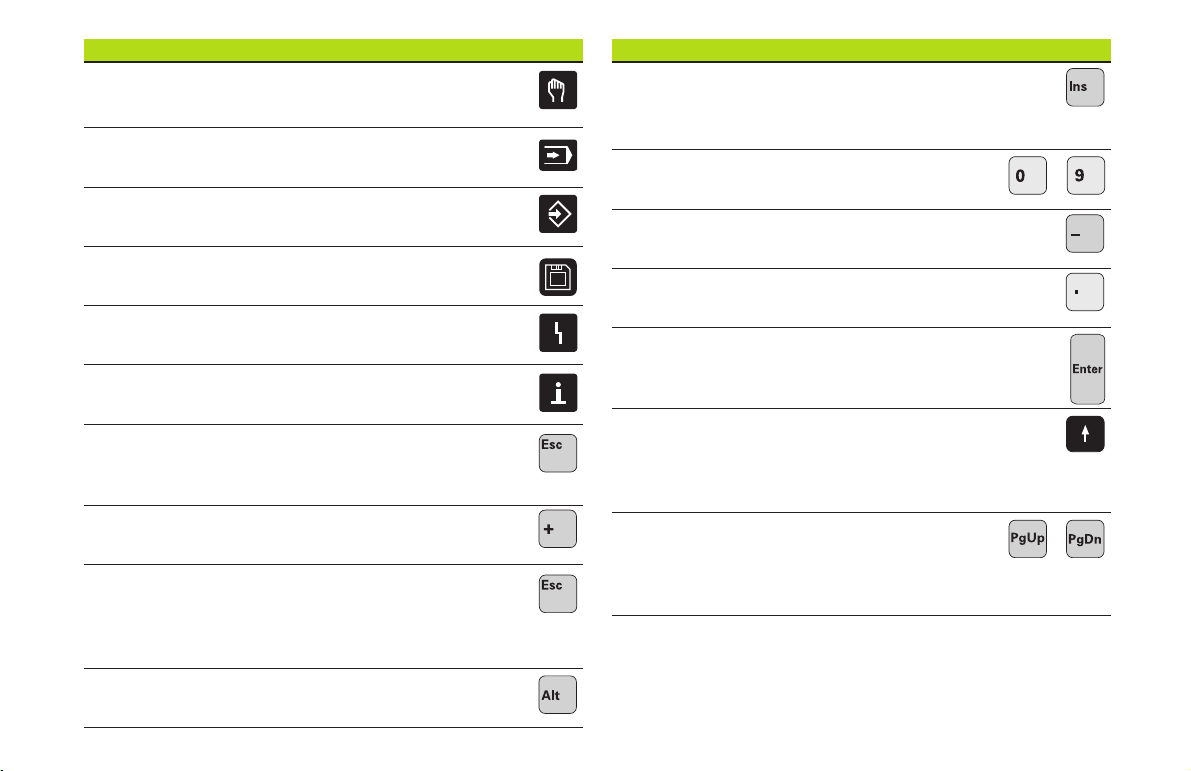
CNC PILOT 4290 V7.0—Keyboard
INS (insert)
■ Insert list element
■ Close dialog box, save data
Numerals (0...9)
For entering numbers and selecting soft keys
Minus
For entering an algebraic sign
Decimal point
Enter
To confirm your input
...
ESC (escape)
■ Go back by one menu level
■ Close dialog box, do not save data
“Continue key”
For special functions (e.g. marking)
DEL (delete)
■ Deletes the list element
■ Deletes the selected character or the character
to the left of the cursor
ALT (alter)
■ Edit the list element
Cursor keys
Moves the cursor by one position
in the direction of the arrow (one
character, one field, one line, etc.)
Page Up, Page Down
■ Go to previous/next screen page
■ Go to previous/next dialog box
■ Switch between input windows
...
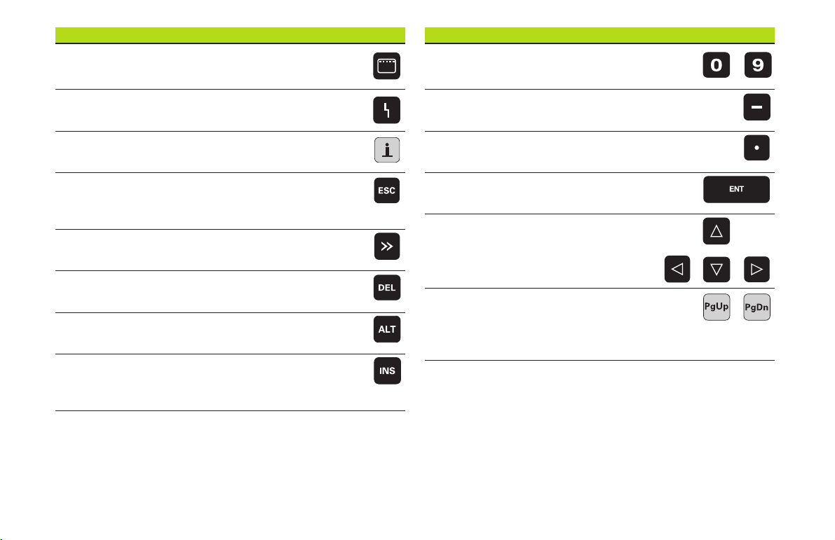
CNC PILOT 4290 V6.4—Keyboard
Operating modes key
Call the selection of operating modes
CNC PILOT 4290 V6.4—Keyboard
Numerals (0...9)
For entering numbers and selecting soft keys
...
Display error status
Call the info system
ESC
■ Go back by one menu level
■ Close dialog box, do not save data
>> (“continue” key)
For special functions (e.g. marking)
DEL
Delete key
ALT (alter)
■ Edit the list element
INS (insert)
■ Insert list element
■ Close dialog box, save data
Minus
For entering an algebraic sign
Decimal point
Enter
To confirm your input
Cursor keys
Moves the cursor by one position
in the direction of the arrow (one
character, one field, one line, etc.)
Page Up, Page Down
■ Go to previous/next screen page
■ Go to previous/next dialog box
■ Switch between input windows
...

4
The Pilot
Contents
... is your concise programming guide for the HEIDENHAIN
CNC PILOT 4290 contouring control. For more comprehensive information on programming and operating, refer to the
CNC PILOT User's Manual.
Certain symbols are used in the Pilot to denote specific types
of information:
Important note!
Warning: Danger for the user or the machine!
Chapter in User's Manual. Here you will find more
detailed information on the current topic.
The information in this Pilot applies to the CNC PILOT with
the software number 340 340 460-xx (release 6.4) and the
CNC PILOT with the software number 368 650-xx (release
7.0).
DIN Programming .............................................................. 6
Overview: G Functions for Contour Description ................ 6
Program Section Codes ..................................................... 8
G Functions for Contour Description ................................. 10
Front, Rear and Lateral Surface Contours.......................... 26
Overview: G Functions for the Machining Part .................. 42
Simple Linear and Circular Movements ............................. 45
Feed Rate, Spindle Speed .................................................. 48
Tool-Tip and Cutter Radius Compensation (TRK) ................ 50
Datum Shifts, Oversizes ................................................... 51
Tools, Compensation ......................................................... 57
Turning, Drilling and Threading Cycles ............................... 59
C-Axis Machining .............................................................. 82
Other G Functions ............................................................. 90
Subprograms ..................................................................... 94
5
DIN Programming
NC blocks start with the letter “N” followed by a block
number (with up to four digits).
Comments are enclosed in parentheses „[...]“. They are
located either at the end of an NC block or in a separate NC
block.
Instructions for operation
During editing, the CNC PILOT shows programmed contours
in a maximum of two simulation windows. You can select
the windows from the DIN PLUS main menu (Menu item
”Graphics—Windows”).
■ The starting point of the contour will be marked with a
”small box”
DIN Programming
■ If the cursor is located on a block from ”blank or finished
part”, the corresponding contour element will be indicated in
red in the simulation window (”Contour display”)
• Additions/changes to the contour will only be
considered if the ”Graphics” menu item is
reactivated.
• Unambiguous NC block numbers are a prerequisite
for the contour display!
• For programming variables, see ”CNC PILOT 4290
User's Manual”
• For programming in the Y axis, see
”CNC PILOT 4290 with Y Axis User's Manual”
Program section codes Page
Program section codes 8
Definition of blank Page
G20-Geo Chuck part, cylinder/tube 10
G21-Geo Cast part 10
Basic elements for contour description Page
G0-Geo Starting point of contour 11
G1-Geo Line segment 11
G2-Geo Arc with incr. center dimensioning 12
G3-Geo Arc with incr. center dimensioning 12
G12-Geo Arc with abs. center dimensioning 12
G13-Geo Arc with abs. center dimensioning 12
Contour form elements Page
G22-Geo Recess (standard) 13
G23-Geo Recess/relief turn 14
G24-Geo Thread with undercut 15
G25-Geo Undercut contour 16
G34-Geo Thread (standard) 19
G37-Geo Thread (general) 20
G49-Geo Bore hole at turning center 22
6

Help commands for contour description Page
Overview: Help commands for contour definition 23
G7-Geo Precision stop ON 23
G8-Geo Cycle stop OFF 23
G9-Geo Precision stop blockwise 23
G10-Geo Peak-to-valley height 23
G38-Geo Feed rate reduction 24
G39-Geo Attributes of superimposed elements 24
G52-Geo Blockwise oversize 25
G95-Geo Feed per revolution 25
G149-Geo Additive compensation 25
Superimposed contours Page
G308-Geo Beginning of pocket/island 26
G309-Geo End of pocket/island 26
Elements of the end face contour Page
G100-Geo Starting point of face contour 27
G101-Geo Line segment on face 27
G102-Geo Circular arc on face 28
G103-Geo Circular arc on face 28
G300-Geo Bore hole on face 29
G301-Geo Linear slot on face 30
G302-Geo Circular slot on face 30
G303-Geo Circular slot on face 30
G304-Geo Full circle on face 31
G305-Geo Rectangle on face 31
G307-Geo Eccentric polygon on face 32
G401-Geo Linear pattern on face 32
G402-Geo Circular pattern on face 33
Elements of the lateral surface contour Page
G110-Geo Starting point of lateral surface contour 34
G111-Geo Line segment on lateral surface 34
G112-Geo Circular arc on lateral surface 35
G113-Geo Circular arc on lateral surface 35
G310-Geo Bore hole on lateral surface 36
G311-Geo Linear slot, lateral surface 37
G312-Geo Circular slot on lateral surface 37
G313-Geo Circular slot on lateral surface 37
G314-Geo Full circle on cylindrical surface 38
G315-Geo Rectangle on lateral surface 38
G317-Geo Eccentric polygon on lateral surface 39
G411-Geo Linear pattern, lateral surface 40
G412-Geo Circular pattern, lateral surface 41
Overviesw: Contour description
Circular arc on lateral surface
7

Program section codes
When you create a new DIN program, certain program section codes are already entered. Delete or
add codes, depending on the task. A DIN program
must include the codes ”MACHINING” and ”END.”
Overview of program section codes
PROGRAMMKOPF [ PROGRAM HEAD ]
TURRET
CLAMPING DEVICE
ROHTEIL [ BLANK ]
FERTIGTEIL [ FINISHED PART ]
FRONT END
REAR END
Program section codes
CYLINDER SURFACE
AUXILIARY CONTOUR
BEARBEITUNG [ MACHINING ]
ENDE [ END ]
SUBPROGRAM
RETURN
PROGRAMMKOPF [ PROGRAM HEAD ]
The PROGRAM HEAD comprises:
■ Organizational information (does not influence
program execution)
■ Setup information (does not influence program
execution)
■ SLIDE: NC program is only executed for the indicated slide – No in-
put: NC program is executed for every slide (input: “$1, $2, ...”)
■ UNIT: unit of measurement ”metric/inches”—No input: the unit set
in control parameter 1 is used
The ”Unit” can be programmed only when a new program is
being created (set under PROGRAM HEAD). It is not possible
to post-edit this entry.
TURRET x
contains the assignment for the tool carrier x (x: 1..6). If the tool is described in the data bank, enter the T number and the ID number. Alternately, you can define the tool parameters in the NC program.
Tool data input:
Call the tool input: INS key
T-number: position in the tool carrier
ID (identification number): reference to the tool database– No in-
put: tool data is not included in the tool database.
Simple tool:
■ Only suitable for simple traverse paths and turning cycles (G0...G3,
G12, G13; G81...G88).
■ There is no regeneration of the contour.
■ Cutter radius compensation is carried out.
■ Data are not stored in the tool database (”Simple tools” have no ID).
Continued
8

Enhanced input: No limitations for use of the tool (data is transferred
to the tool database during program conversion.)
If you do not program TURRET, the tools entered in the turret
table will be used.
CLAMPING DEVICE x
Defines the type of clamping device X used on the spindle (x: 1..4).
If you do not program CLAMPING DEVICE, the machining simulation
assumes there is no clamping device (see also G65).
Parameters
H: Clamping device number (reference for G65) – Range: 1 H 9
ID: Identification number of clamping device
X: Clamping diameter
Q: Chucking shape – defines the position of the clamping device ref-
erence point (see G65)
ROHTEIL [ BLANK ]
Program section for the definition of the blank.
FERTIGTEIL [ FINISHED PART ]
Program section for the contour definition of the finished part.
Additional program section codes within the finished part definition:
■ FRONT END Z.. : Section ”Front end contour” – ”Z..” defines the po-
sition of the front contour.
■ REAR SIDE Z.. : Section ”Rear side contour” – ”Z..” defines the posi-
tion of the rear side contour.
■ LATERAL SURFACE X.. : section ”Lateral surface
contour” – ”X..”
■ AUXILIARY CONTOUR: indicates further contour
definitions
If you have several independent contour definitions, then repeated use of the program
section codes (FRONT END, REAR END,
etc.) is permitted.
BEARBEITUNG [ MACHINING ]
Program section for the machining of the workpiece.
MACHINING must be included in your program.
ENDE [ END ]
Ends your NC program. The code END must be
included in your program (replaces M30).
SUBPROGRAM ”12345678”
If you define a subprogram within your NC program
(within the same file), it is identified with
SUBPROGRAM, followed by the name of the
subprogram (max. 8 characters).
RETURN
Ends your NC subprogram.
Program section codes
9
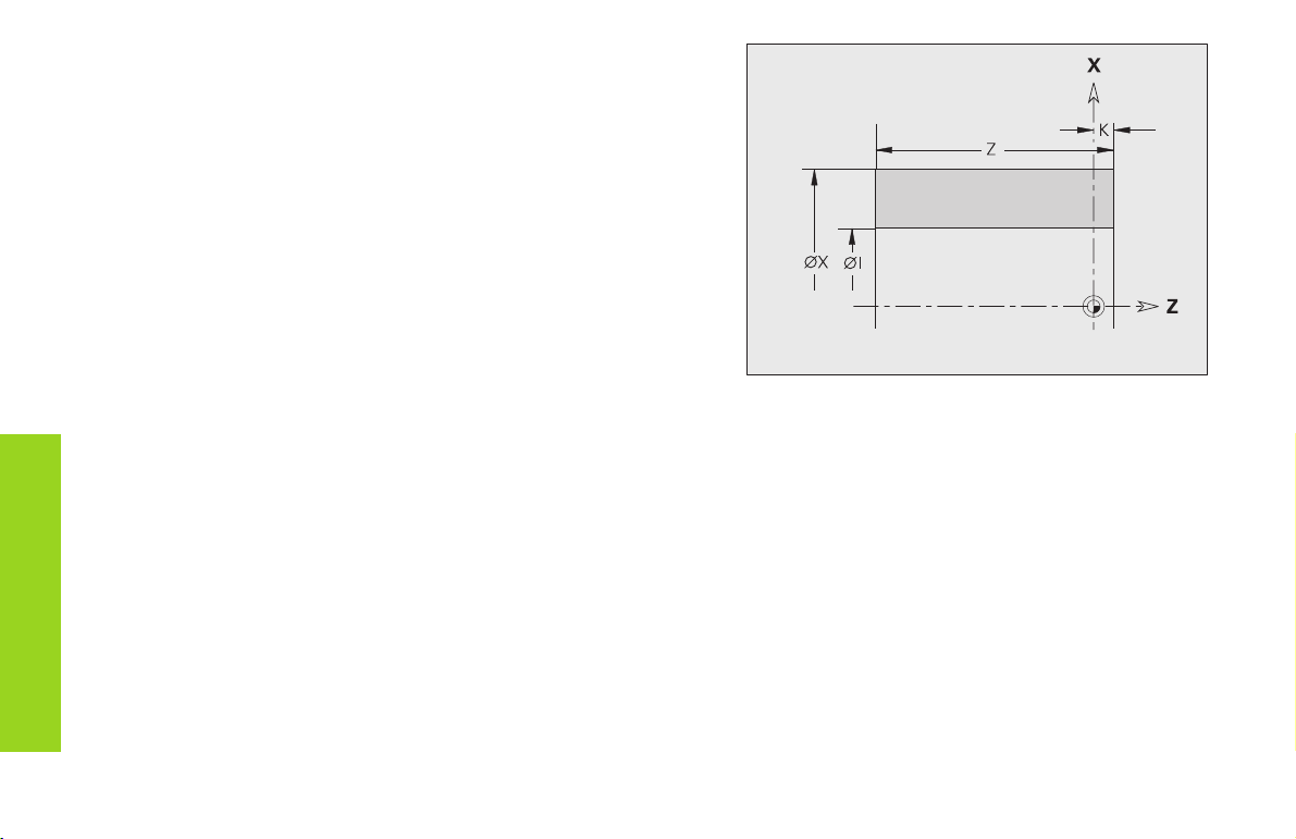
Blank material for cylinder/pipe G20-Geo
G20 defines the contour of a cylinder/hollow cylinder.
Parameters
■ Diameter of cylinder/hollow cylinder
X:
■ Diameter of circumference of polygonal blank
Z: Length of blank
K: Right edge (distance between workpiece datum and right edge)
I: Inside diameter for hollow cylinders
Definition of blank
Cast part G21-Geo
G21 generates the contour of the blank part from the contour of the
finished part – plus the ”equidistant allowance P.”
Parameters
P: Equidistant finishing allowance (reference: finished part contour)
Q: Bore holes yes/no – default: Q=0
■ Q=0: without bore holes
■ Q=1: with bore holes
10
Starting point of turning contour G0 Geo
G0 defines the starting point of a turning contour.
Parameters
X, Z: Starting point of the contour (X diameter value)
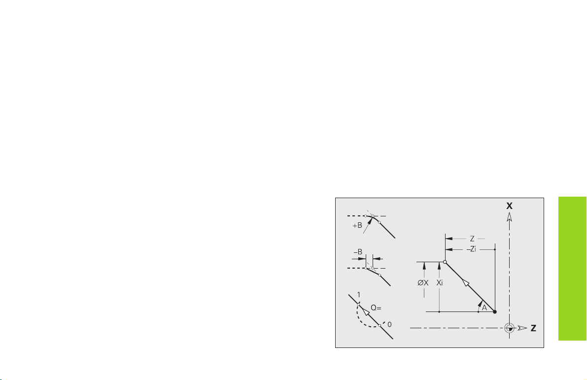
Line segment in a contour G1-Geo
G1 defines a line segment in a turning contour.
Parameters
X, Z: End point (X diameter value)
A: Angle to rotary axis – for angle direction see illustration
Q: Select point of intersection – default: 0
■ Q=0: Near intersection
■ Q=1: Far intersection
B: Chamfer/rounding
■ B is undefined: Tangential transition
■ B=0: Nontangential transition
■ B>0: Rounding radius
■ B<0: Chamfer width
E: Special feed-rate factor (0 < E 1) – default: 1
(special feed rate = active feed rate * E)
Basic elements for
11
contour description
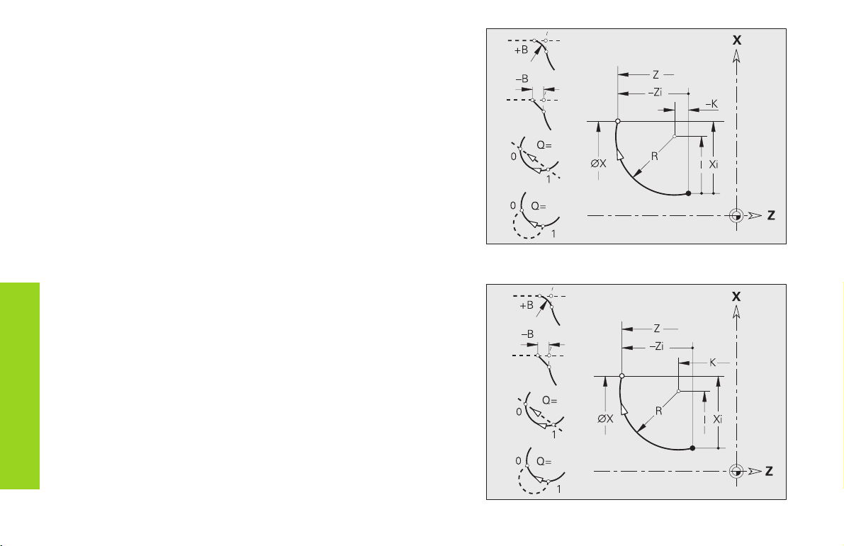
Circular arc in a contour
G2/G3-Geo – incremental, G12/G13-Geo – absolute center
coordinates
G2/G3 or G12/G13 defined a circular arc in a contour. The direction of
rotation is visible in the help graphic.
Parameters
X, Z: End point (X diameter value)
R: Radius
Q: Selection of intersection – default: 0
■ Q=0: Far intersection
■ Q=1: Near intersection
B: Chamfer/ rounding at end of circular arc
■ B no entry: tangential transition
■ B=0: no tangential transition
■ B>0: Radius of rounding
Basic elements for
contour description
■ B<0: Width of chamfer
E: Special feed-rate factor (0 < E 1) – default: 1
(special feed rate = active feed rate * E)
With G2/G3:
I: Center point incremental (distance from starting point to center
as radius)
K: Center point incremental (distance from starting point to center)
With G12/G13:
I: Absolute center (radius)
K: Absolute center
Example: G2-Geo
12
Example: G12-Geo
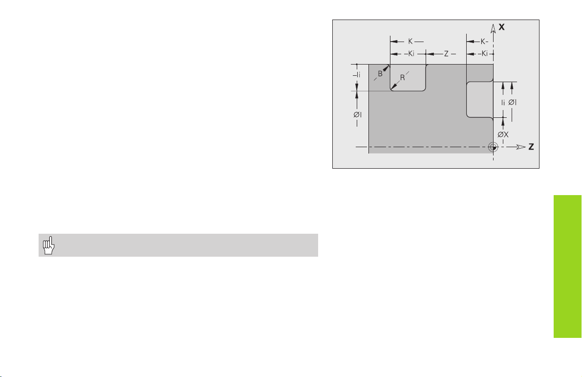
Recess (standard) G22-Geo
G22 defines a recess on an axis-parallel reference element (G1). G22 is
assigned to the previously programmed reference element.
Parameters
X: Starting point of recess on the end surface (diameter)
Z: Starting point of recess on lateral surface
I, K: Inside corner
■ I for recess on front face: recess end point (diameter value)
■ K for recess on end face: recess base
■ I for recess on lateral surface: recess base (diameter value)
■ K for recess on lateral surface: recess end point
Ii, Ki: Inside corner – incremental (pay attention to sign !)
■ Ii for recess on end face: recess width
■ Ki for recess on end face: recess depth
■ Ii for recess on lateral surface: recess depth
■ Ki for recess on lateral surface: end point of recess (recess
width)
B: Outside radius/chamfer (at both ends of the recess) – default: 0
■ B>0: Radius of the rounding
■ B<0: Width of the chamfer
R: Inside radius (in both corners of recess) – default: 0
Program either X or Z.
Form elements
for contour description
13

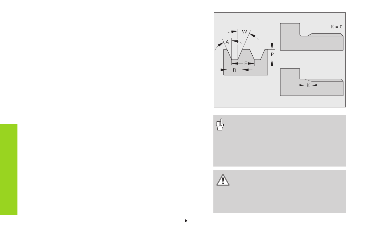
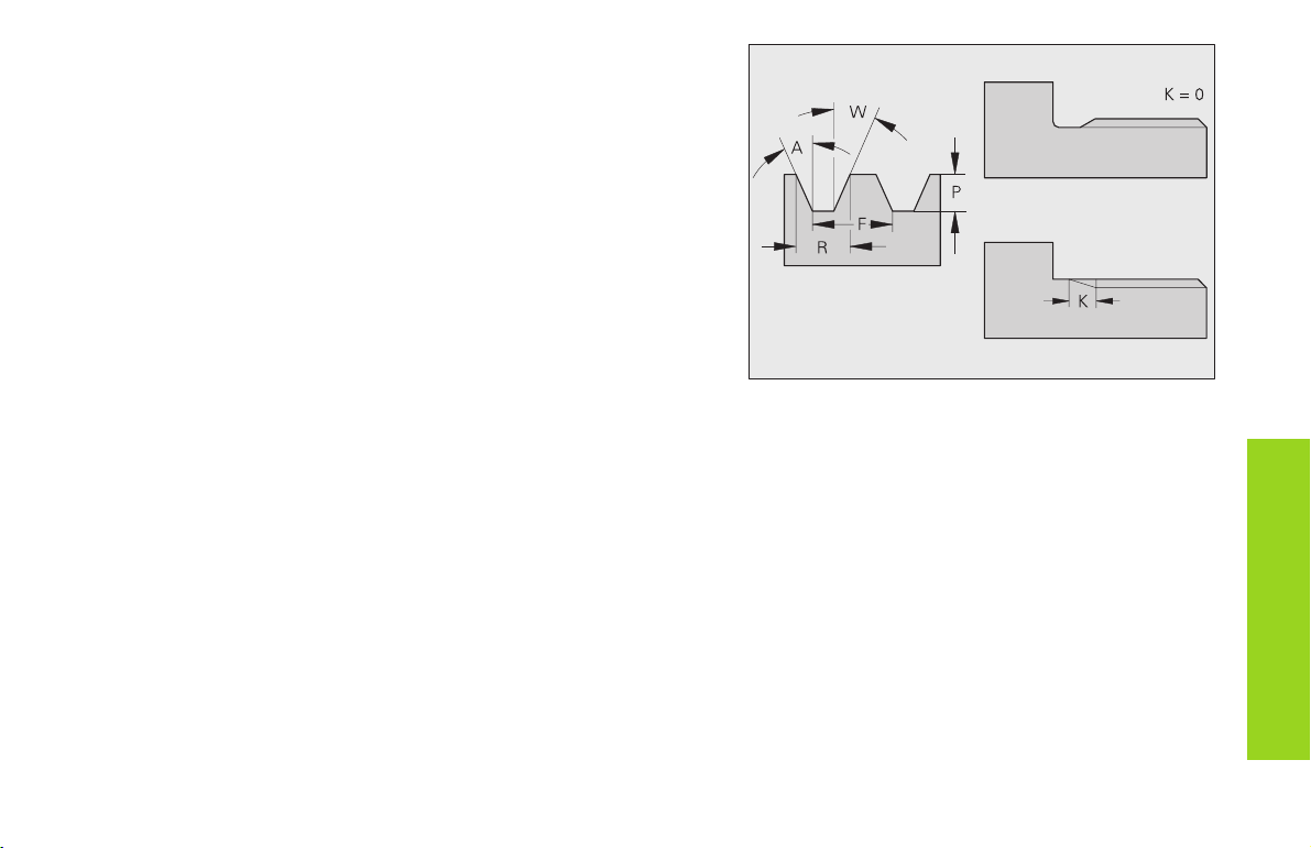
Recess (general) G23-Geo
G23 defines a recess on a linear reference element (G1). G23 is
assigned to the previously programmed reference element. On the lateral surface the recess can be positioned on an inclined reference
straight.
Parameters
H: Recess type – default: 0
■ H=0: symmetrical recess
■ H=1: free rotation
X: Center point of recess on end surface (diameter)
Z: Center point of recess on lateral surface
I: Recess depth and position
■ I>0: recess to right of reference element
■ I<0: recess to left of reference element
K: Recess width (without chamfer/rounding)
Form elements
for contour description
U: Recess diameter (diameter of recess floor) – use only if the
reference element runs parallel to the Z axis.
A: Recess angle – default: 0
■ with H=0: 0° A < 180° (angle between edges of recess)
■ with H=1: 0° < A 90° (angle between reference straight and
recess edge)
B: Outside radius/corner. Starting point near corner - default: 0
■ B>0: Radius of rounding
■ B<0: Width of chamfer
P: Outside radius/corner. Starting point distant from corner - default: 0
■ P>0: Radius of rounding
■ P<0: Width of chamfer
R: Inside radius (in both corners of recess) – default: 0
Simple recess
14
The CNC PILOT refers the recess depth to the reference
element. The recess base runs parallel to the reference
element.
Recess or free rotation
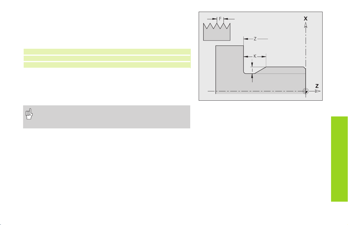
Thread with undercut G24-Geo
G24 defines a linear base element, a linear thread (external or internal
thread; metric ISO fine-pitch thread DIN 13 Part 2, Series 1) and a subsequent thread undercut (DIN 76).
Calling the contour macro:
N..G1 X..Z..B.. /Starting point for thread
N..G24 F..I..K..Z.. /Contours for thread and undercut
N..G1 X.. /Next surface element
Parameters
F: Thread pitch
I: Depth of undercut (radius)
K: Width of undercut
Z: End point of the undercut
• G24 can be used only if the thread is cut in the direction of
contour definition.
• The thread is machined with G31.
Form elements
for contour description
15
Undercut contour G25-Geo
G25 generates the following undercut contours in paraxial contour
corners. The meaning of the parameters depends on the type of
undercut.
If you program G25
■ after the reference element, the undercut is turned at the end of the
reference element.
■ before the reference element, the undercut is turned at the
beginning of the reference element.
Calling the contour macro (example):
N..G1 Z.. /Linear element as reference
N..G25 H..I..K.. .. /Undercut contour
N..G1 X.. /Next surface element
Form elements
for contour description
Parameters
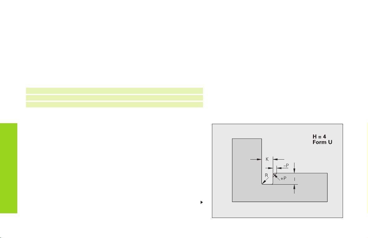
Undercut form U (H=4)
Parameters
I: Depth of undercut (radius)
K: Width of undercut
R: Inside radius (in both corners of recess) – default: 0
P: Outside radius/chamfer – default: 0
■ P>0: radius of the rounding
■ P<0: width of the chamfer
H: Type of undercut – default: 0
■ H=4: undercut form U
■ H=0, 5: undercut form DIN 509 E
■ H=6: undercut form DIN 509 F
■ H=7: thread undercut DIN 76
■ H=8: undercut form H
■ H=9: undercut form K
16
Continued
Undercut form U (H=4)
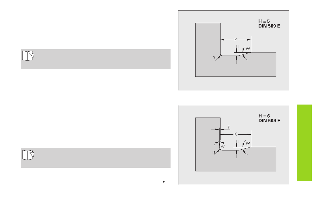
Undercut DIN 509 E (H=0, 5)
Parameters
I: Depth of undercut (radius)
K: Width of undercut
R: Undercut radius (in both corners of the undercut)
W: Undercut angle
If you do not enter any parameters the CNC PILOT calculates
the values from the diameter (see User's Manual, section
“Undercut Parameters DIN 509 E”).
Undercut DIN 509 F (H=6)
Parameters
I: Depth of undercut (radius)
K: Width of undercut
R: Undercut radius (in both corners of the undercut)
P: Transverse depth
W: Undercut angle
A: Transverse angle
If you do not enter any parameters the CNC PILOT calculates
the values from the diameter (see User's Manual, section
“Undercut Parameters DIN 509 F”).
Continued
Undercut DIN 509 E (H=0, 5)
Undercut DIN 509 F (H=6)
Form elements
for contour description
17
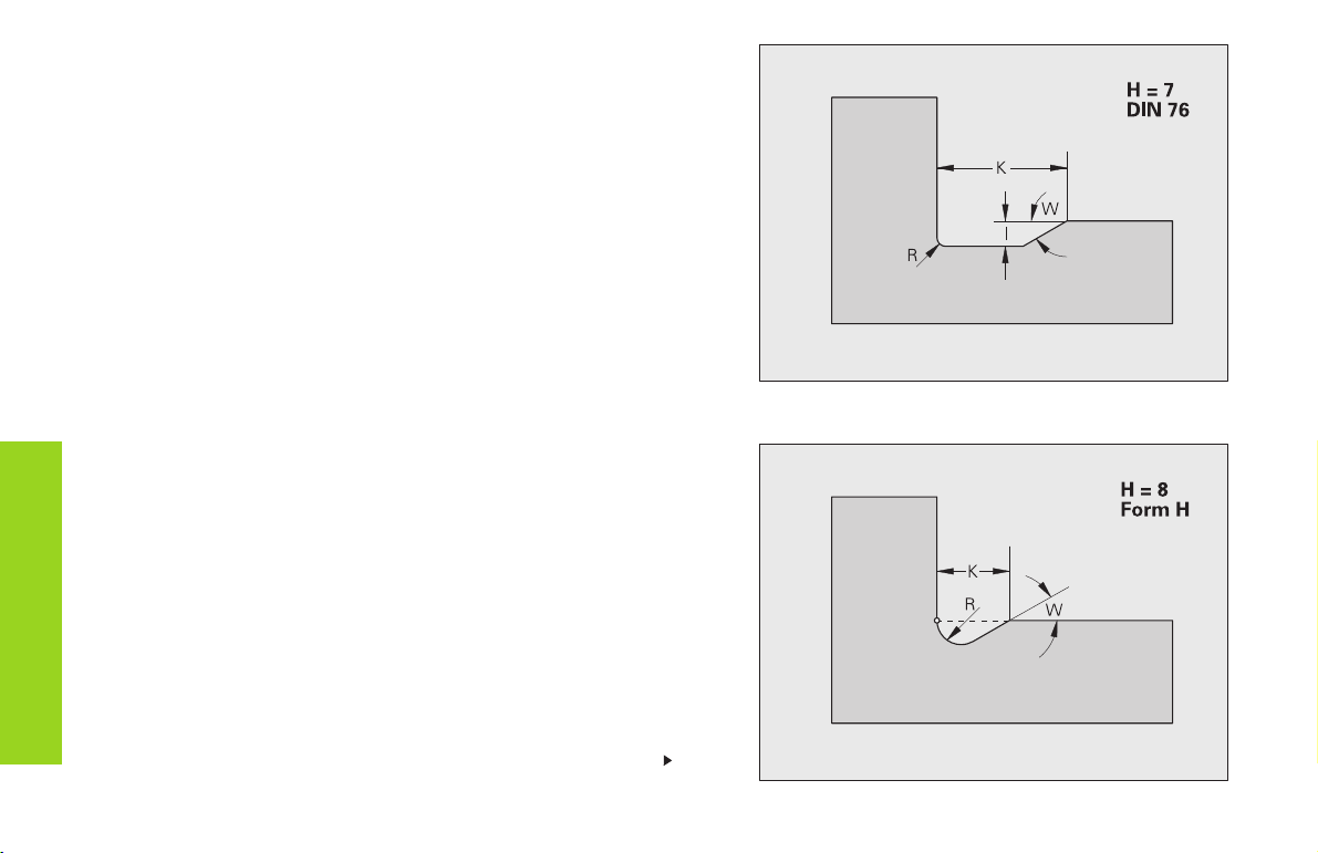
Undercut DIN 76 (H=7)
Parameters
I: Depth of undercut (radius)
K: Width of undercut
R: Undercut radius (in both corners of the undercut) – default:
R=0.6*I
W: Undercut angle – default: 30°
Form elements
for contour description
Undercut form H (H=8)
If you do not enter W, it will be calculated on the basis of K and R. The
final point of the undercut is then located at the ”final point contour.”
Parameters
K: Width of undercut
R: Undercut radius – no value: the circular element is not machined
W: Plunge angle – no value: W is calculated
18
Undercut DIN 76 (H=7)
Continued
Undercut form H (H=8)
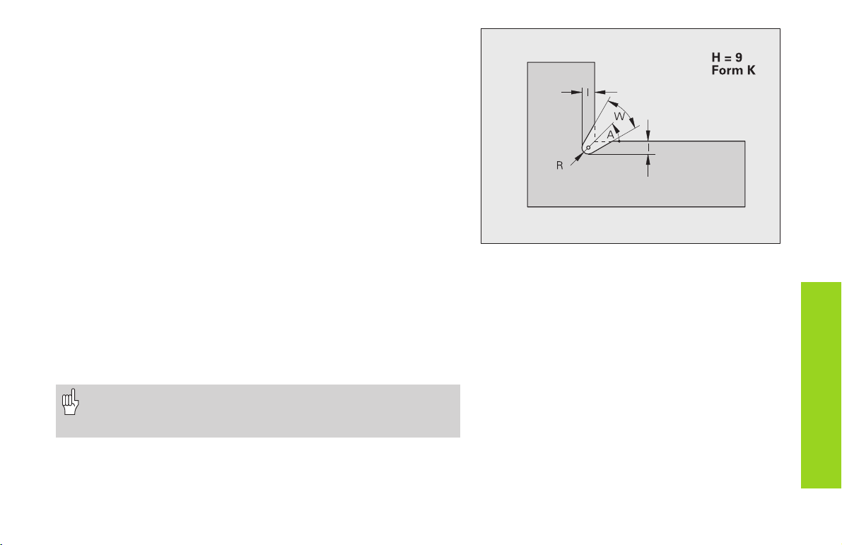
Undercut form K (H=9)
Parameters
I: Undercut depth
R: Undercut radius – no value: the circular element is not machined
W: Undercut angle
A: Angle to linear axis – default: 45°
Thread (standard) G34-Geo
G34 defines a simple or an interlinked external or internal thread (metric
ISO fine-pitch thread DIN 13 Series 1). Threads are interlinked by
programming several G01/G34 blocks after each other.
Parameters
F: Thread pitch – no value: pitch from the standard table
• You need to program a linear contour element as a reference
before G34 or in the NC block containing G34.
• The thread is cut with G31.
Undercut form K (H=9)
Form elements
for contour description
19
Thread (general) G37-Geo
G37 defines the different types of thread. Threads are interlinked by
programming several G01/G34 blocks after each other.
Parameters
Q: Type of thread – default: 1
■ Q=1: metric ISO fine-pitch thread (DIN 13 Part 2, Series 1)
■ Q=2: metric ISO thread (DIN 13 Part 1, Series 1)
■ Q=3: metric ISO taper thread (DIN 158)
■ Q=4: metric ISO tapered fine-pitch (DIN 158)
■ Q=5: metric ISO trapezoid thread (DIN 103 Part 2, Series 1)
■ Q=6: flat metric trapezoid thread (DIN 308 Part 2, Series 1)
■ Q=7: metric buttress thread (DIN 13 Part 2, Series 1)
■ Q=8: cylindrical round thread (DIN 405 Part 1, Series 1)
■ Q=9: cylindrical Whitworth thread (DIN 259)
■ Q=10: tapered Whitworth thread (DIN 2999)
■ Q=11: Whitworth pipe thread (DIN 2999)
Form elements
for contour description
■ Q=12: nonstandard thread
■ Q=13: UNC US coarse thread
■ Q=14: UNF US fine-pitch thread
■ Q=15: UNEF US extra-fine-pitch thread
■ Q=16: NPT US taper pipe thread
■ Q=17: NPTF US taper dryseal pipe thread
■ Q=18: NPSC US cylindrical pipe thread with lubricant
■ Q=19: NPFS US cylindrical pipe thread without lubricant
F: Thread pitch – must be entered for Q=1, 3..7, 12.
P: Thread depth – enter only for Q=12.
K: Runout length (for threads without undercut) –
default: 0
• Program a linear contour element as a
reference before G37.
• The thread is cut with G31.
• For standard threads, the parameters P, R,
A and W are defined by the CNC PILOT.
• Use Q=12 if you wish to use individual
parameters.
The thread is generated to the length of the
reference element. For the machining of
threads without an undercut, it is necessary
to program an additional linear element so
that the overrun can be executed by the CNC
PILOT without danger of collision.
20
Continued
D: Reference point (position of thread runout) – default: 0
■ D=0: runout at end of reference element
■ D=1: runout at beginning of reference element
H: Number of grooves – default: 1
A: Edge angle left – enter only for Q=12.
W: Edge angle right – enter only for Q=12.
R: Thread width – enter only for Q=12.
E: Variable pitch (increases/reduces the pitch per revolution by E) –
default: 0
Form elements
for contour description
21
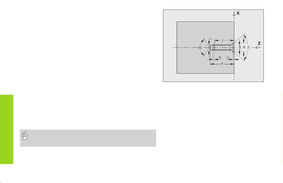
Bore hole (centered) G49-Geo
G49 defines a single bore hole with countersink and thread at the
turning center (front or end face).
Parameters
Z: Starting position for hole (reference point)
B: Bore hole diameter
P: Depth of hole (excluding point)
W: Point angle – default: 180°
R: Countersinking diameter
U: Countersinking depth
E: Countersinking angle
I: Thread diameter
J: Thread depth
K: Thread runout length
Form elements
for contour description
F: Thread pitch
V: Left-hand or right-hand thread - default: 0
■ V=0: Right-hand thread
■ V=1: Left-hand thread
A: Angle (position of bore hole) – default: 0
■ A=0: front end
■ A=180: tail end
O: Centering diameter
• G49 is programmed in the FINISHED PART section (not in
the FRONT or REAR SIDE section).
• The contour defined with G49 is machined with G71...G74.
22
Overview: Help commands for contour description
G7 Accurate stop ON
G8 Accurate stop OFF
G9 Accurate stop blockwise
G10 influences finishing feed rate for total contour
G38 influences finishing feed rate for basic contour elements block
by block
G39 Only for form elements:
■ influences finishing feed rate
■ additive compensation values
■ equidistant finishing allowances
G52 Equidistant finishing allowances – blockwise
G95 defines finishing feed rate for total contour
G149 additive compensation values for total contour
Accurate stop ON G7-Geo
G7 switches the ”precision stop” on modally. In a ”precision stop,” the
CNC PILOT does not start the next block until the ”tolerance window”
around the end point is reached (for tolerance window, see machine
parameters 1106, 1156, ...).
• The NC block containing G7 is also executed with a precision
stop.
•”Precision stop” is used for basic contour elements that are
executed with G890 or G840.
Precision stop OFF G8-Geo
G8 switches the precision stop off. The block containing G8 is executed
without a precision stop.
Blockwise accurate stop G9-Geo
G9 activates a precision stop for the NC block in
which it is programmed (see also ”G7 Geo”).
Peak-to-valley height (surface texture)
G10-Geo
G10 influences the finishing feed rate of G890 and
thus determines the surface roughness of the
workpiece.
Basics of programming
■ The peak-to-valley height activated with G10 is mo-
dal.
■ G10 without parameters deactivates peak-to-valley
height.
■ G95 Geo deactivates peak-to-valley height.
■ G10 RH... (without ”H”) overwrites the valid peak-
to-valley roughness block by block.
■ G38 Geo overwrites the valid peak-to-valley
roughness block by block.
Parameters
H: Type of surface texture (see also DIN 4768)
■ H=1: general roughness (profile depth) Rt1
■ H=2: average roughness Ra
■ H=3: mean roughness Rz
RH: Peak-to-valley roughness (in µm, inches: µinch)
The peak-to-valley height applies only for
basic contour elements.
Help commands for
contour description
23

Feed rate reduction factor G38-Geo
G38 defines a special feed rate for G890.
Parameters
E: Special feed-rate factor (0 < E 1) – default: 1
(special feed rate = active feed rate * E)
Basics of programming
■ G38 is a non-modal function.
■ G38 is programmed before the contouring
element for which it is destined.
■ G38 replaces another special feed rate or a
programmed peak-to-valley height.
The ”special feed rate” applies only for basic
contour elements.
Attributes for superimposed elements G39-Geo
G39 influences the machining of G890 for the superimposed
Help commands
for contour description
elements (form elements):
✲■ Chamfers/rounding arcs (for connecting base elements)
■ Undercuts
■ Recesses
Influence on machining:
■ Special feed rate
■ Peak-to-valley height
■ Additive D compensation
■ Equidistant oversizes
Parameters
F: Feed per revolution
V: Type of surface texture (see also DIN 4768)
■ V=1: general roughness (profile depth) Rt1
■ V=2: average roughness Ra
■ V=3: mean roughness Rz
RH: Peak-to-valley height (µm, inch mode: µinch)
D: Number of the additive compensation (901 D 916)
24
P: Finishing allowance (radius)
H: (Translation of P) absolute / additive – default: 0
■ H=0: P replaces G57/G58 allowances
■ H=1: P is added to G57/G58 allowances
E: Special feed-rate factor (0 < E 1) – default: 1
(special feed rate = active feed rate * E)
Basics of programming
■ G39 is a non-modal function.
■ G39 is programmed before the contour element
for which it is destined.
■ G50 before a cycle (MACHINING section) switches
G39 oversizes for this cycle off.
Only use peak-to-valley height (”V, RH”),
finishing allowance (”F”) and special feed
rate (”E”) alternately!

Blockwise finishing allowance G52-Geo
G52 defines an equidistant finishing allowance which is taken into
consideration in G810, G820, G830, G860 and G890.
Basics of programming
■ G52 is a non-modal function.
■ G52 is programmed in the NC block containing the contour element
for which it is destined.
■ G50 before a cycle (MACHINING section) switches G52 oversizes for
this cycle off.
Parameters
P: Finishing allowance (radius)
H: (Translation of P) absolute / additive – default: 0
■ H=0: P replaces G57/G58 allowances
■ H=1: P is added to G57/G58 allowances
Feed rate per revolution G95-Geo
G95 influences the finishing feed rate of G890.
Basics of programming
■ G95 is a modal function
■ G10 switches the G95 finishing feed rate off.
Parameters
F: Feed per revolution
• Use peak-to-valley height and finishing feed rate alternatively.
• The G95 finishing feed rate replaces a finishing feed rate
defined in the machining program.
Additive compensation G149-Geo
The CNC PILOT manages 16 tool-independent
correction values.
To activate the additive correction function, program
G149 followed by a „D number“ (for example, G149
D901). ”G149 D900” resets the additive
compensation function.
Basics of programming
■ Additive compensation is effective from the block
in which G149 is programmed.
■ An additive compensation remains active until:
• the next ”G149 D900”
• the end of the finished part description
Parameters
D: Additive compensation - Default: D900
Range: 900 to 916
Note the direction of contour description!
Help commands for
contour description
25
Start of pocket/island G308-Geo
G308 defines a new reference level/reference diameter for
hierarchically nested front face or lateral surface contours.
Parameters
P: Depth for pocket, height for islands
The algebraic sign of ”Depth P” defines the position of the milling
contour:
■ P<0: Pocket
■ P>0: Island
Section P Surface Milling floor
FRONT END P<0 Z Z+P
FRONT END P>0 Z+P Z
REAR END P<0 Z Z–P
Overlapped contours
REAR END P>0 Z–PZ
CYLINDER SURFACE P<0 X X+(P*2)
CYLINDER SURFACE P>0 X+(P*2) X
The milling cycles machine from the ”surface” toward the ”milling
floor.”
X: Reference diameter from the section code
Z: Reference plane from the section code
P: ”Depth” from G308 or from the cycle parameters
• Note with ”P”: the addition of a negative
number reduces the result, and the
subtraction of a negative number increases
the result.
• Island: The area-milling cycles machine
the complete area specified in the contour
definition. Islands that are defined within
this area are not considered.
26
End pocket/island G309-Geo
G309 ends a reference level. Every reference plane defined with G308
must be ended with G309!
Starting point of end face contour G100-Geo
G100 defines the starting point of an end face contour.
Parameters
X, C: Starting point in polar coordinates (diameter, starting angle)
XK,YK: Starting point in Cartesian coordinates
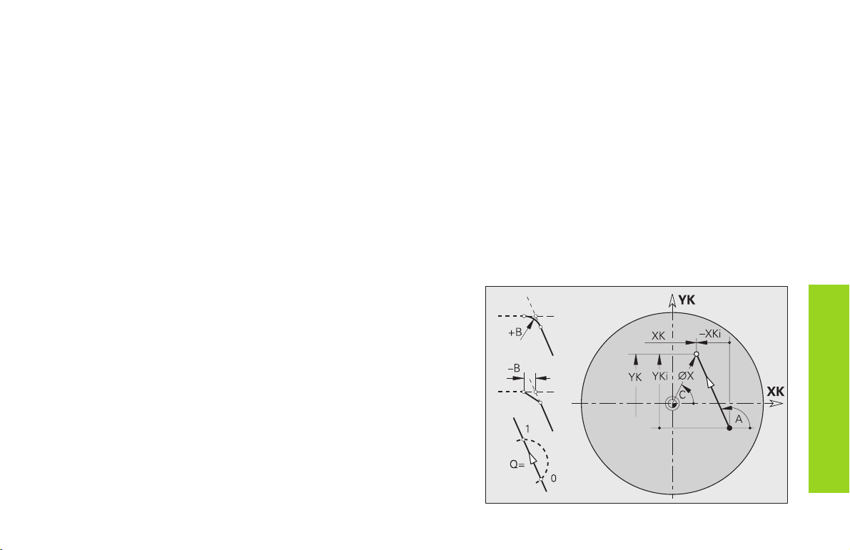
Linear segment in end face contour G101-Geo
G101 defines a line segment in an end face contour.
Parameters
X, C: End point in polar coordinates (diameter, end angle)
XK,YK: End point in Cartesian coordinates
A: Angle to positive XK-axis
B: Chamfer/rounding
■ B is undefined: Tangential transition
■ B=0: Nontangential transition
■ B>0: Rounding radius
■ B<0: Chamfer width
Q: Select point of intersection – default: 0
■ Q=0: Near intersection
■ Q=1: Far intersection
Base elements for
front/end face contour
27
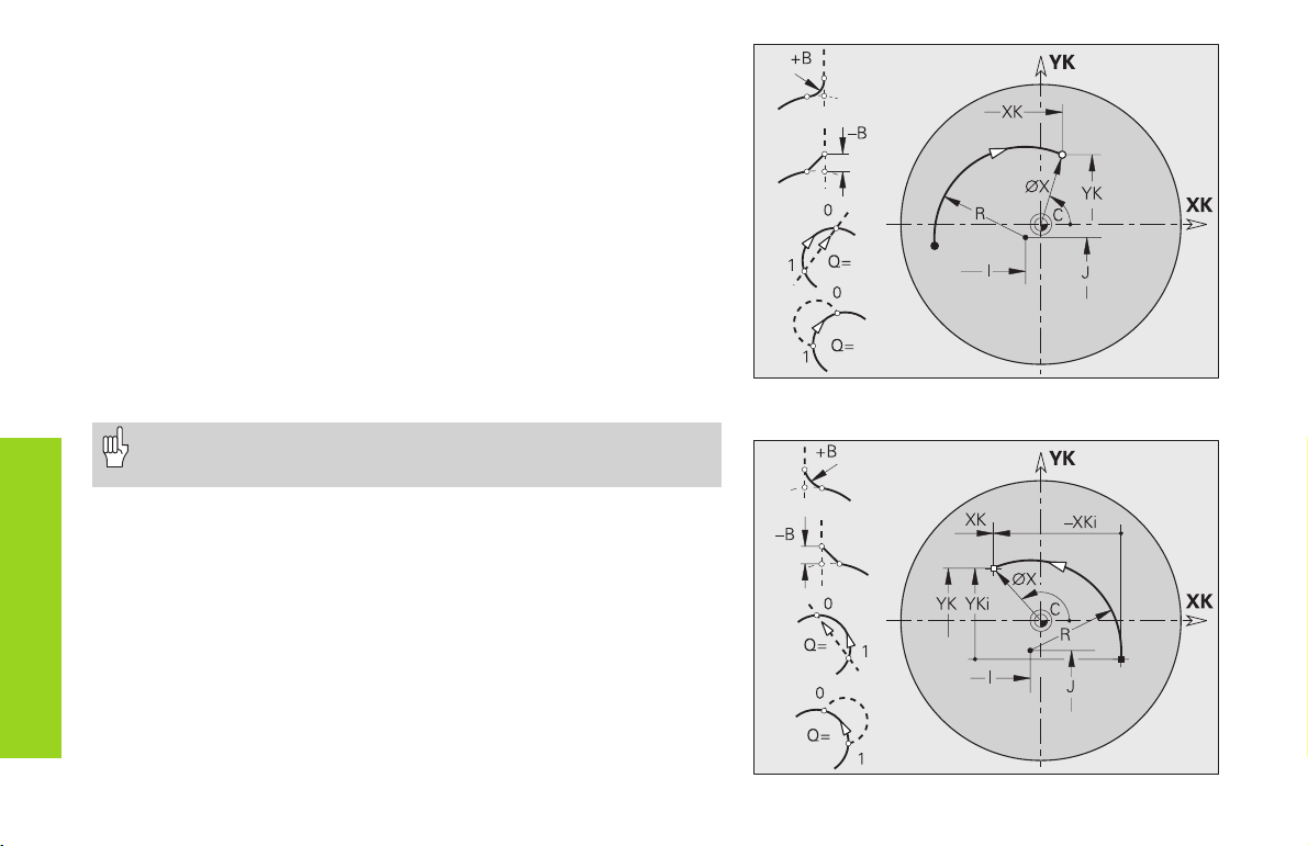
Circular arc in front end contour G102-/G103-Geo
G102/G103 defines a circular arc in a front/end face contour. The
direction of rotation is visible in the help graphic.
Parameters
X, C: End point in polar coordinates (diameter, end angle)
XK,YK: End point in Cartesian coordinates
R: Radius
I, J: Center in Cartesian coordinates
Q: Selection of intersection – default: 0
■ Q=0: Far intersection
■ Q=1: Near intersection
B: Chamfer/ rounding at end of circular arc
■ B no entry: tangential transition
■ B=0: no tangential transition
Base elements for
front/end face contour
■ B>0: Radius of rounding
■ B<0: Width of chamfer
The end point may not be the same as the starting point (not a
full circle).
G102-Geo
28
G103-Geo
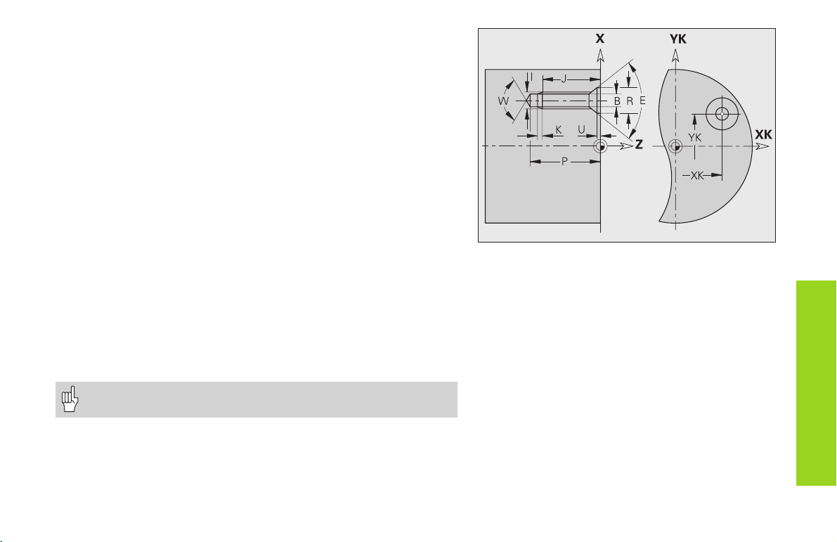
Bore hole on end face G300-Geo
G300 defines a bore hole with countersink and thread on the front/end
face.
Parameters
XK,YK: Center of hole
B: Hole diameter
P: Depth of hole (excluding point)
W: Point angle – default: 180°
R: Countersinking diameter
U: Countersinking depth
E: Countersinking angle
I: Thread diameter
J: Thread depth
K: Thread runout length
F: Thread pitch
V: Left-hand or right-hand thread - default: 0
■ V=0: Right-hand thread
■ V=1: Left-hand thread
A: Angle (reference: Z-axis)
■ Front end – default: 0° (range: –90° < A < 90°)
■ Rear end – default: 180° (range: 90° < A < 270°)
O: Centering diameter
Use G71...G74 to machine bore holes defined with G300-Geo.
Figures on end face contour
29
 Loading...