


CNC Pilot 4290
Table of contents
 Loading...
User’s Manual
CNC PILOT 4290
B and Y Axis
NC Software
625 952-xx
English (en)
4/2010

CNC PILOT 4290 B and Y Axis
This manual describes functions and features that are available for the
B axis, the Y axis and the tool magazine in the CNC PILOT 4290 with
NC software number 625 952-xx (Release 7.1). This manual is a
supplement to the CNC PILOT 4290 User's Manual.
CNC PILOT 4290 B and Y Axis
2 B and Y Axis

1 B and Y Axis ..... 7
1.1 Basics ..... 8
The Y axis ..... 8
The B axis ..... 8
The tool magazine ..... 10
1.2 Manual Control and Automatic Modes ..... 11
Automatic mode without reference run ..... 11
Magazine list ..... 11
Working with magazine tools ..... 14
Measuring and compensating magazine tools ..... 18
Tool compensation in automatic mode ..... 19
1.3 Programming Notes ..... 20
Milling contour position ..... 20
Cutting limit ..... 20
Drilling and milling in a tilted plane ..... 21
1.4 DIN PLUS: Section Codes ..... 22
PLATE MAGZN. section ..... 22
FRONT_Y, REAR_SIDE_Y section ..... 22
SURFACE_Y section ..... 23
1.5 DIN PLUS: Contours in the XY Plane ..... 24
Starting point of contour G170 Geo ..... 24
Linear element G171 Geo ..... 24
Circular arc G172/G173 Geo ..... 25
Hole G370 Geo ..... 26
Linear slot G371 Geo ..... 26
Circular slot G372/G373 Geo ..... 27
Full circle G374 Geo ..... 27
Rectangle G375 Geo ..... 28
Eccentric polygon G377 Geo ..... 28
Linear pattern in XY plane, G471-Geo ..... 29
Circular pattern in XY plane, G472 Geo ..... 30
Single surface G376 Geo ..... 31
Centric polygon G477 Geo ..... 31
HEIDENHAIN CNC PILOT 4290 3

1.6 DIN PLUS: Contours in the YZ Plane ..... 32
Starting point of contour G180 Geo ..... 32
Linear element G181 Geo ..... 32
Circular arc G182/G183 Geo ..... 33
Hole G380 Geo ..... 34
Linear slot G381 Geo ..... 34
Circular slot G382/G383 Geo ..... 35
Full circle G384 Geo ..... 35
Rectangle G385 Geo ..... 36
Eccentric polygon G387 Geo ..... 36
Linear pattern in YZ plane, G481-Geo ..... 37
Circular pattern in YZ plane, G482-Geo ..... 38
Single surface G386 Geo ..... 39
Centric polygon G487 Geo ..... 39
1.7 DIN PLUS: Working Planes ..... 40
Tilting the working plane G16 ..... 41
1.8 DIN PLUS (Y Axis): Positioning Commands ..... 42
Rapid traverse G0 ..... 42
Approach tool change point G14 ..... 42
Rapid traverse to machine coordinates G701 ..... 43
1.9 DIN PLUS: Magazine Tools ..... 44
Insert magazine tool G714 ..... 44
Define tool position G712 ..... 47
Preselect tool G600 ..... 48
1.10 DIN PLUS: Linear and Circular Paths ..... 49
Milling: Linear movement G1 ..... 49
Milling: Circular movement G2, G3—incremental center coordinates ..... 50
Milling: Circular path G12, G13—absolute center coordinates ..... 51
1.11 DIN PLUS (Y Axis): Milling Cycles ..... 52
Area milling—roughing G841 ..... 52
Area milling—finishing G842 ..... 53
Centric polygon milling—roughing G843 ..... 54
Centric polygon milling—finishing G844 ..... 55
Pocket milling - roughing G845 (Y axis) ..... 56
Pocket milling—finishing G846 (Y axis) ..... 61
Engrave in XY plane G803 ..... 63
Engrave in YZ plane G804 ..... 64
Thread milling in XY plane G800 ..... 65
Thread milling in YZ plane G806 ..... 66
Hobbing G808 ..... 67
1.12 Simulation ..... 68
Simulation of the tilted plane ..... 68
Displaying the coordinate system ..... 69
Position display with the B and Y axes ..... 69
4

1.13 TURN PLUS: Tool Magazine and B Axis ..... 70
Tool magazine ..... 70
Tools for the B axis ..... 70
1.14 TURN PLUS: Y Axis ..... 71
Y axis - Basics ..... 71
Definition of milling contours ..... 72
1.15 TURN PLUS: XY Plane Contours ..... 73
Reference data - XY front/XYR back ..... 73
XY plane: Starting point of contour ..... 74
XY plane: Linear element ..... 75
XY plane: Arc ..... 76
XY plane: Single hole ..... 77
XY plane: Circle (full circle) ..... 79
XY plane: Rectangle ..... 80
XY plane: Polygon ..... 81
XY plane: Linear slot ..... 82
XY plane: Circular slot ..... 83
XY plane: Linear drilling pattern ..... 84
XY plane: Circular drilling pattern ..... 85
XY plane: Linear figure pattern ..... 86
XY plane: Circular figure pattern ..... 87
XY plane: Single surface ..... 88
XY plane: Centric polygon ..... 88
1.16 TURN PLUS: YZ Plane Contours ..... 89
Reference data - Y lateral surface ..... 89
YZ plane: Starting point of contour ..... 89
YZ plane: Linear element ..... 90
YZ plane: Arc ..... 91
YZ plane: Single hole ..... 92
YZ plane: Circle (full circle) ..... 94
YZ plane: Rectangle ..... 95
YZ plane: Polygon ..... 96
YZ plane: Linear slot ..... 97
YZ plane: Circular slot ..... 98
YZ plane: Linear drilling pattern ..... 99
YZ plane: Circular drilling pattern ..... 100
YZ plane: Linear figure pattern ..... 101
YZ plane: Circular figure pattern ..... 102
Single surface in YZ plane ..... 103
Centric polygons in YZ plane ..... 103
1.17 Example Programs ..... 104
Machining with the Y axis ..... 104
Machining with the B axis ..... 109
HEIDENHAIN CNC PILOT 4290 5

B and Y Axis
HEIDENHAIN CNC PILOT 4290 7
1.1 Basics
The Y axis
With a Y axis you can drill and mill a workpiece on its front, back and
lateral surfaces.
1.1 Basics
During use of the Y-axis, two axes interpolate linearly or circularly in
the given working plane, while the third axis interpolates linearly. This
enables you to machine slots or pockets, for example, with plane
floors and perpendicular edges. By defining the spindle angle, you can
determine the position of the milling contour on the workpiece.
The CNC PILOT supports part program creation with the Y axis in:
DIN PLUS
TURN PLUS contour definition
TURN PLUS working plan generation
The separation of contour description and machining also applies to
milling with the Y axis. Contour regeneration is not available for milling
operations.
Y axis contours are identified with section codes.
The graphical simulation shows the milling operation in the familiar
lathe, front, and surface windows, as well as in the "side view (YZ)."
The B axis
Tilted working plane
The B axis makes it possible to drill, bore and mill in oblique planes. To
make programming easy, the coordinate system is tilted in such a way
that you can define the drilling patterns and milling contours in the YZ
plane. The actual drilling or milling operation is then performed in the
tilted plane.
The separation of contour description and machining also applies to
machining operations in tilted planes. Contour regeneration is not
available.
Contours in tilted planes are identified with the section code
SURFACE_Y.
The CNC PILOT supports part program creation with the B axis in DIN
PLUS.
The graphical simulation shows the machining operation in a tilted
working plane in the familiar lathe and front windows, as well as in the
“side view (YZ).”
8
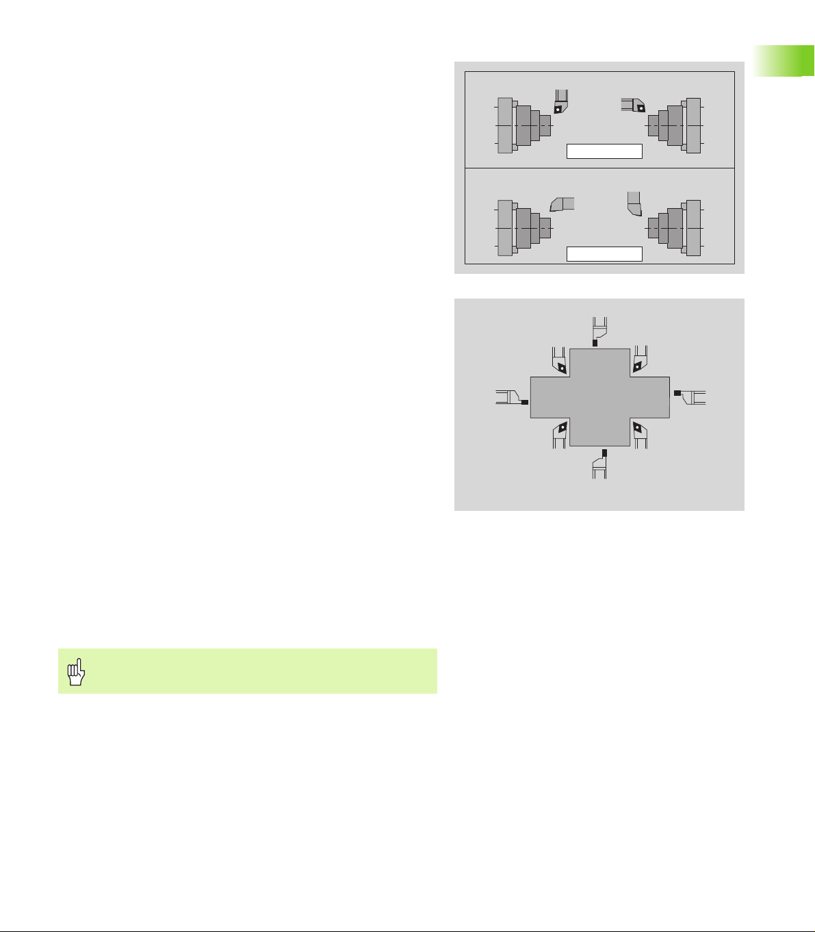
Tools for the B axis
B0 B90
G714 B.. C180
B90
B180
G714 B.. C0
O=
1
3
7
5
2
4
6
8
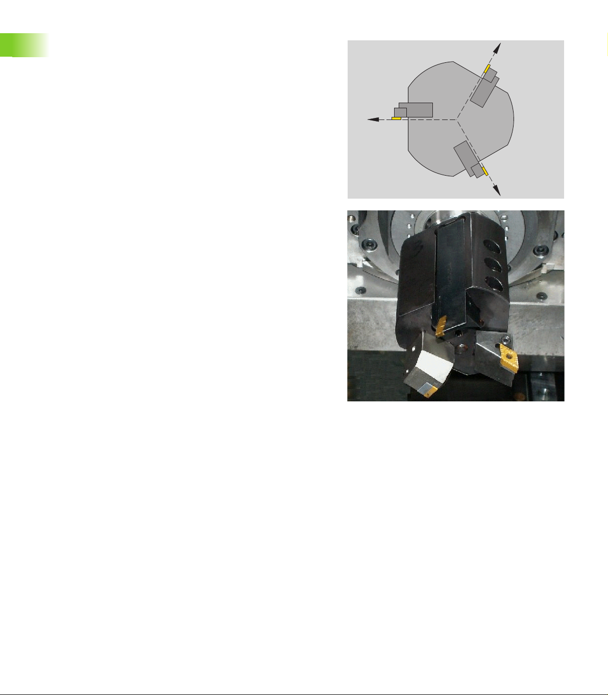
Another advantage of the B axis is that it allows flexible use of the
tools during turning operations. By tilting the B axis and rotating the
tool you can bring it into positions that enable you to use one and the
same tool to machine in the longitudinal and transverse (or radial and
axial) directions on the main and opposing spindles.
In this way, you need fewer tools and fewer tool changes.
Tool data: All tools are described in the tool database by specifying
the X, Z and Y dimensions as well as the compensation values. These
dimensions are referenced to the tilt angle B=0°.
Another parameter that is maintained in the tool database is the
position angle. It defines the working positions of tools that are not
driven tools (turning tools).
The tilt angle of the B axis is not maintained with the tool data. This
angle needs to be defined in the tool call or when inserting the tool.
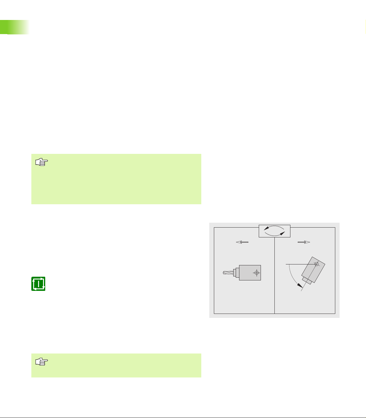
Tool orientation and position display: For turning tools, the position
the tool tip is calculated based on the orientation of the cutting edge.
This orientation is not regenerated automatically when the B axis is
tilted and/or rotated.
When the B axis has been moved manually, the control marks the
position display invalid.
Display with black digits: Position display is valid.
Display with gray digits: Position display is invalid.
After moving the B axis, please check whether the orientation is still
valid and reassign it, if necessary.
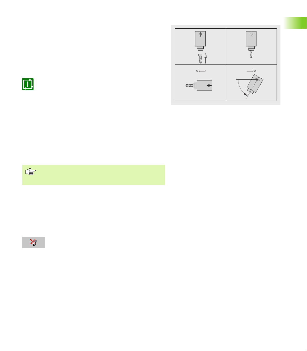
When orienting tools, the control distinguishes between roughing,
finishing and button tools as well as recessing and threading tools (see
figure).
Tool positions 1, 3, 5 or 7 apply to roughing, finishing and button
tools. The control recognizes neutral tools by the tool angle.
Tool positions 2, 4, 6 or 8 apply to recessing and threading tools.
Whether the tool is a “right-hand” or a “left-hand” tool is defined in
the tool data.
Machine display: The T box in the machine display indicates the
tool's pocket in the magazine. The current tilt angle of the B axis is
taken into account in the compensation values shown in this box.
1.1 Basics
After tilting or rotating the B axis, the values given in the
position display are invalid.
HEIDENHAIN CNC PILOT 4290 9
Multipoint tools for the B axis
C0
C120
C240
If several tools are mounted on a tool holder, this is are referred to as
a “multipoint tool.” Each cutting edge (tool) of a multipoint tool is
assigned a separate ID number and description.
The position angle, which is identified by “C” in the figure, is
included in the tool data. When a cutting edge (tool) of a multipoint tool
1.1 Basics
is activated, the CNC PILOT will rotate the multipoint tool into the
correct position. The position is determined from the position angle, to
which the offset position angle from the tool change routine is added.
This allows inserting the tool either in the “normal” attitude or “upside
down.”
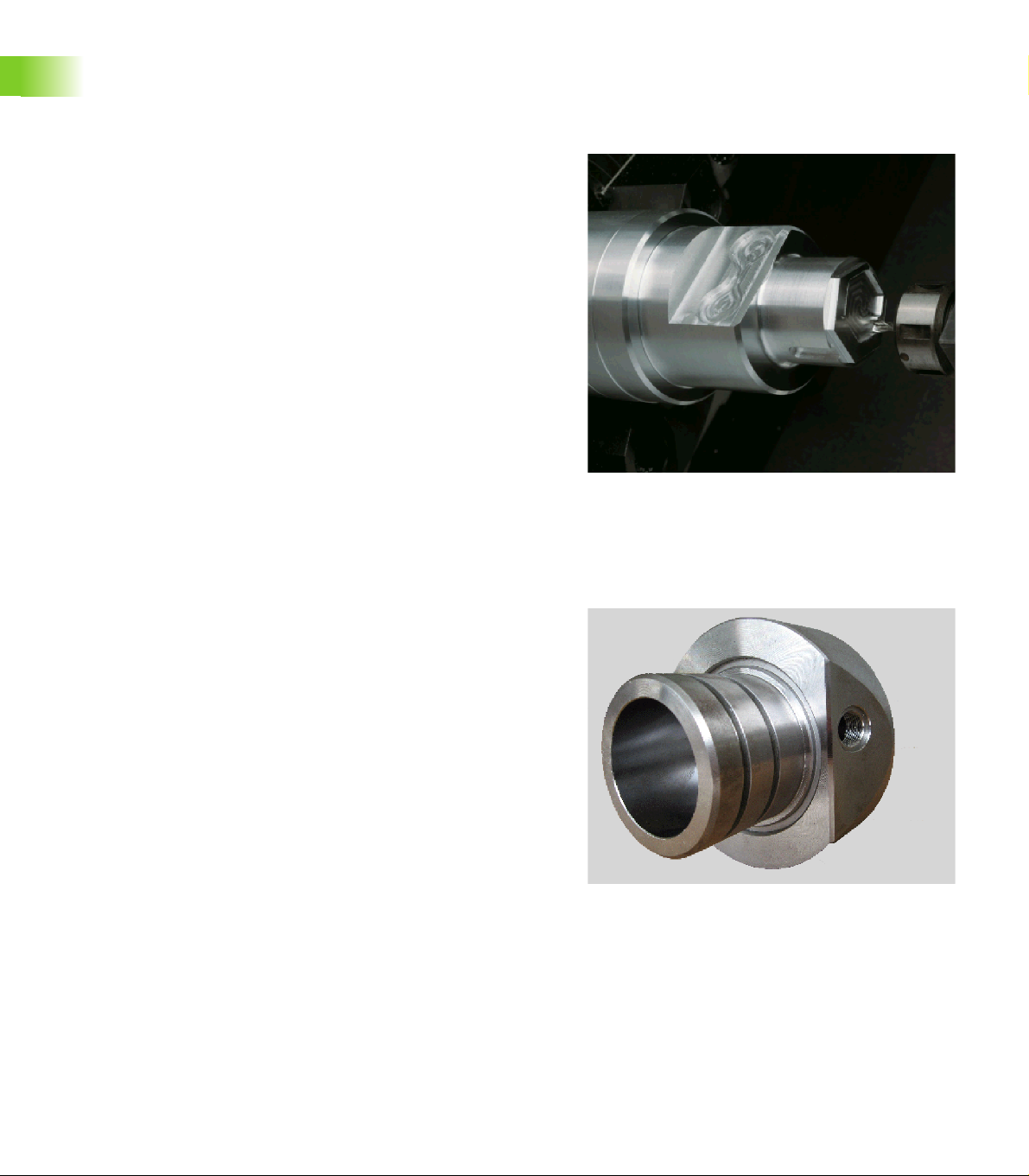
The photo shows a multipoint tool with three cutting edges.
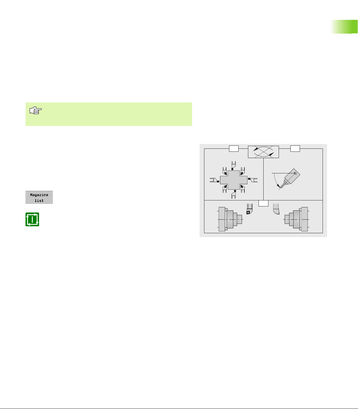
The tool magazine
The CNC PILOT supports a pocket-based tool magazine with up to 99
tools. Pocket-based means that each tool is assigned a specific pocket
in the magazine. The machine operator assigns the pockets when
setting up the magazine.
The magazine list indicates the current assignment of the tool
magazine. The tools are entered in this list with their ID numbers.
Tool programming: The magazine tools are intended for the B axis.
The command G714 is provided for changing and positioning the tools.
Alternatively, you can also use single commands (G0, G15, etc.) to
program a tilting of the B axis and a rotation of the tool to the position
angle. Please note, however, that you will need to declare the tool
position with G712 in that case.
10

1.2 Manual Control and Automatic
Modes
Automatic mode without reference run
As of software version 625 952-02:
You can start magazine programs and manual programs even if you
have not traversed the reference marks in all the axes. To use this
function, add a comment line to the program you want to start. In this
comment line you define which axes are allowed without a reference
status.
Syntax of the comment line:
[@0nn]—where nn stands for the address letters of the non-
referenced axes
Examples:
[@0B]—the B axis does not have to be referenced
[@0BY]—the B and Y axes do not have to be referenced
The functions for setting up the tool magazine and for
inserting the magazine tools are interfaced to the CNC
PILOT and the machine by the machine tool builder. The
functionality provided on your machine may therefore
differ from the functions described in this manual. Your
machine manual provides more detailed information.
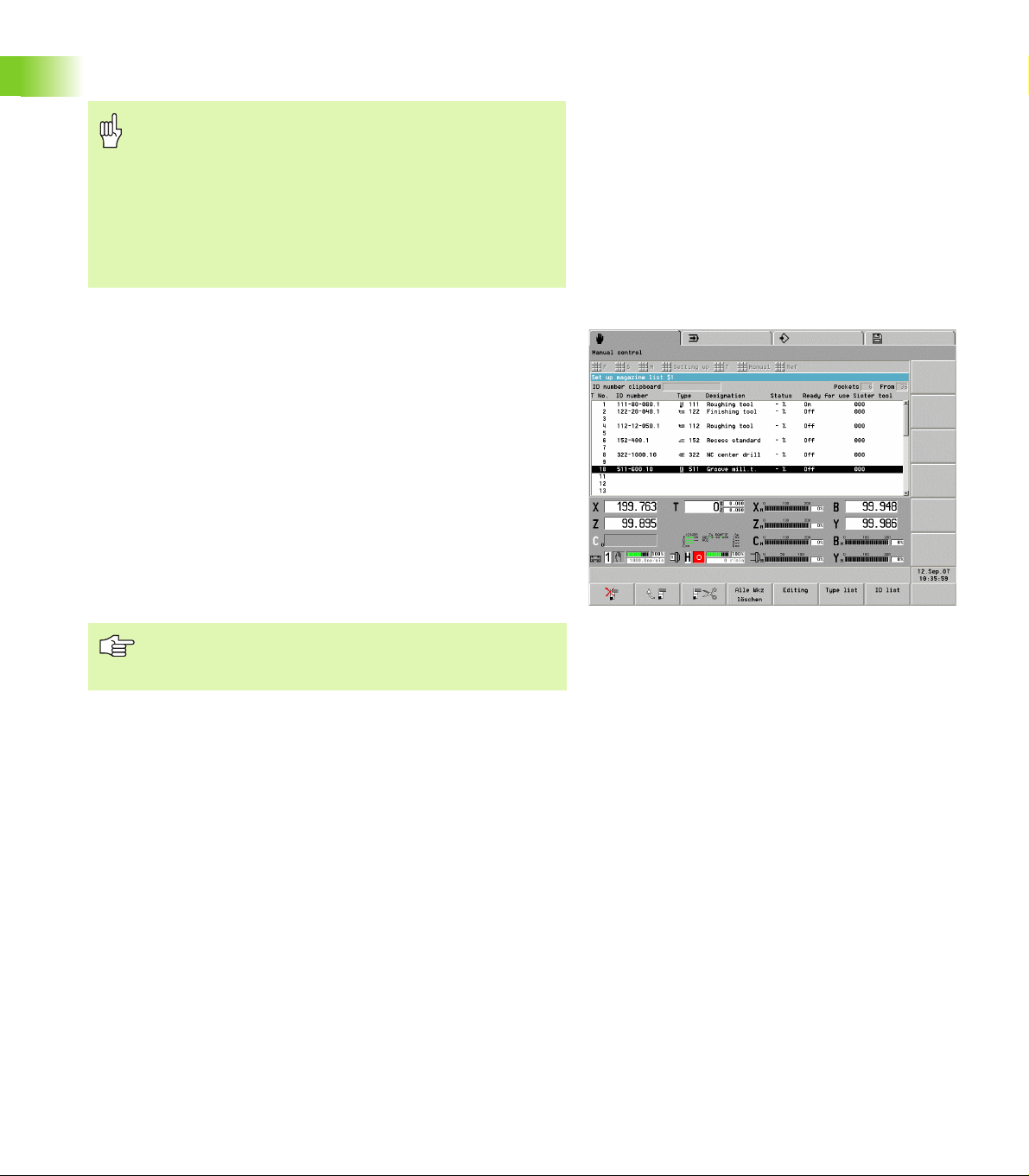
Magazine list
The magazine list indicates the current assignment of the tool
magazine. When setting up the magazine list, you assign each tool a
specific magazine pocket by entering the tool's ID number. For a
multipoint tool, you can enter the ID number of any cutting edge of
the tool. From that ID number, the CNC PILOT determines all other
cutting edges of the multipoint tool, since all ID numbers of a
multipoint tool are interlinked in the tool database.
The tool magazine can be set up in different ways:
Adding tools to the magazine by using the loading hatch: see
“Adding tools to the magazine by using the loading hatch” on
page 12
Adding tools to the magazine from the machine working space:
see “Adding tools to the magazine from the machine working
space” on page 13
Removing tools from the magazine: see “Removing tools from
the magazine” on page 13
HEIDENHAIN CNC PILOT 4290 11
1.2 Manual Control and Automatic Modes
The tool life management also applies to magazine tools without
restriction.
Danger of collision
Compare the magazine list with the tools actually in the
tool magazine and check the tool data before executing
the part program.
The magazine list and the dimensions of the registered
tools must correspond to the tools actually present,
because the CNC PILOT used this data for all slide
movements, protective zone monitoring, and other slide
movements.
Adding tools to the magazine by using the loading hatch
You can add a tool to the magazine by inserting it through the loading
hatch and assigning the tool's ID number to a specific pocket of the
magazine list.
To enter the tool ID number:
U Select “Setting up > Tool list > Setup list” in manual
control mode.
U Place the cursor on the magazine pocket you want to
assign to the tool.
U Select the tool's ID number from the database and
confirm, or press the INS key and type in the ID
number directly.
1.2 Manual Control and Automatic Modes
U Rotate the tool magazine to the corresponding
position and insert the tool.
The functions “Compare tool list with NC program” and
“Load tool list from NC program” are not available for the
magazine list.
12
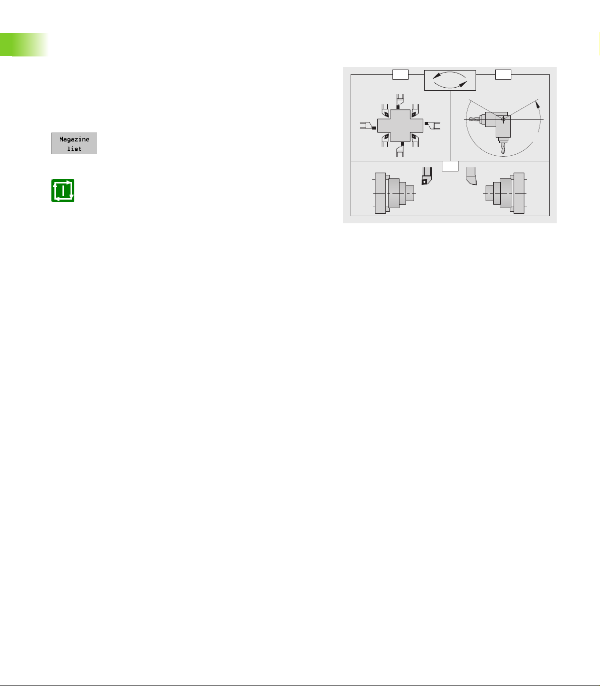
Adding tools to the magazine from the machine working space
B
1. 2.
3. 4.
ID . . .
P . . .
Insert the tool in the tool holder and call the “Load plate” function.
Enter the ID number of the tool and the magazine pocket number. The
CNC PILOT inserts the tool in the magazine and enters the ID number
in the magazine list.
U Insert the tool in the tool holder (in the machine's working space).
U Select “T > Magazine > Load plate” in manual control mode. The
CNC PILOT opens the “Magazine: Load plate” dialog box.
U Enter the parameters and click OK to close the dialog box. The
control loads the associated NC program.
U Activate the NC program with Cycle Start.
Parameters
ID ID number of the magazine tool.
P Pocket number in the tool magazine.
B B axis angle. Angle to which the B axis is tilted.
The CNC PILOT
inserts the tool in the magazine,
enters the tool in the magazine list,
moves the slide to the tool change position, and
tilts the B axis,
Note on operation and display: This function is executed
using an NC program. To activate the NC program, press
Cycle Start.
Removing tools from the magazine
Remove the tool from the magazine and delete the entry in the
magazine list.
U Rotate the tool magazine to the corresponding position and remove
the tool.
U Select “Setting up > Tool list > Setup list” in manual control mode.
U Place the cursor on the magazine pocket of the tool you removed.
U Press the soft key or the DEL key and click yes on the
confirmation prompt. The control deletes the tool
from the magazine list.
1.2 Manual Control and Automatic Modes
HEIDENHAIN CNC PILOT 4290 13
Working with magazine tools
C=0° C=180°
0°
B
O=
13
75
2
4
6
8
C
BO
T
M
Changing magazine tools
You can use this function to change the tool or to modify the tilt angle
or position angle of the active tool.
U Select “T > Magazine > Tool change” in manual
control mode. The control opens the “Magazine: Tool
change” dialog box.
U Press the soft key, select the tool from the magazine
list, enter the additional parameters and click OK to
close the dialog box. The control loads the associated
NC program.
U Activate the NC program with Cycle Start.
Parameters
ID ID number of the magazine tool.
O Orientation of turning tools. Position of the tool's cutting edge
(see figure).
Tool positions 1, 3, 5, 7: For roughing, finishing and button
tools (neutral tools are recognized by the tool angle).
Tool positions 2, 4, 6, 8: For recessing and threading cycles
(a “right-hand” or “left-hand” tool is defined in the tool
data).
B B axis angle. Angle to which the B axis is tilted.
C Offset position angle of turning tools.
1.2 Manual Control and Automatic Modes
0°: Tool attitude “normal”
180°: Tool attitude “upside down”
H Shoe brake
0: The brake is locked depending on the tool parameter (if
“not driven” the brake is locked; if “driven” the brake is not
locked)
1: The brake is locked
2: The brake is not locked
The CNC PILOT
inserts the tool in the magazine,
takes the specified tool from the magazine,
moves to the tool change position,
tilts the B axis,
rotates the tool to the “normal” or “upside down” attitude (offset
position angle C),
calculates the tool data, taking the “orientation O,” the B axis
position and the position angle into account, and
adjusts the brake settings.
14
Changing the tool position: If the call refers to the active tool, the
C=0° C=180°
B
T
M
O=
13
75
2
4
6
8
C
BO
slide moves to the tool change position and tilts the B axis or rotates
the tool to the position angle.
Offset position angle: With the “offset position angle” you can
position turning tools in the “normal” attitude or “upside down.”
When positioning the tool, the CNC PILOT also takes the basic setting
saved in the tool database into account (position angle = position angle
from the tool data + offset position angle).
Tool orientation: The CNC PILOT takes the orientation of the cutting
edge into account when calculating the position of the tool tip. The
control distinguishes between roughing, finishing and button tools as
well as recessing and threading tools (see figure).
Note on operation and display: This function is executed
using an NC program. To activate the NC program, press
Cycle Start.
Declaring magazine tools
If there is a tool in the machine's working space when the control is
switched off and on again, the tool needs to be redeclared. In the
corresponding dialog box, the CNC PILOT automatically suggests the
values in effect when the control was switched off.
U Select “T > Magazine > Manual tool” in manual
control mode. The control opens the “Magazine:
Manual tool” dialog box.
U Press the soft key, enter the B axis angle, check all
other parameters and click OK to close the dialog box.
The control loads the associated NC program.
U Activate the NC program with Cycle Start.
1.2 Manual Control and Automatic Modes
Parameters
ID ID number of the magazine tool.
P Pocket number in the tool magazine.
O Orientation of turning tools. Position of the tool's cutting edge
(see figure).
Tool positions 1, 3, 5, 7: For roughing, finishing and button
tools (neutral tools are recognized by the tool angle).
Tool positions 2, 4, 6, 8: For recessing and threading cycles
(a “right-hand” or “left-hand” tool is defined in the tool
data).
B B axis angle. Angle to which the B axis is tilted.
C Offset position angle of turning tools.
0°: Tool attitude “normal”
180°: Tool attitude “upside down”
HEIDENHAIN CNC PILOT 4290 15
Parameters
B
T 0
M
H Shoe brake
0: The brake is locked depending on the tool parameter (if
“not driven” the brake is locked; if “driven” the brake is not
locked)
1: The brake is locked
2: The brake is not locked
The CNC PILOT
moves to the tool change position,
tilts the B axis,
rotates the tool to the “normal” or “upside down” attitude (offset
position angle C),
calculates the tool data, taking the “orientation O,” the B axis
position and the position angle into account, and
adjusts the brake settings.
The information on the tool in the tool holder is not
saved when the control is switched off. HEIDENHAIN
therefore recommends to remove magazine tools from
the working space before switching off the control.
Note on operation and display: This function is executed
using an NC program. To activate the NC program, press
Cycle Start.
1.2 Manual Control and Automatic Modes
Returning tools to the magazine
The “Return tool to magazine” function moves the tool from the
machine's working space back into the magazine. The tool carrier then
approaches the tool change position and tilts the B axis to the
specified angle.
U Select “T > Magazine > Return tool” in manual control mode. The
control opens the “Magazine: Return tool” dialog box.
U Enter the “B axis angle B” parameter and click OK to close the
dialog box. The control loads the associated NC program.
U Activate the NC program with Cycle Start.
Parameters
B B axis angle. Angle to which the B axis is tilted.
The CNC PILOT
inserts the tool in the magazine,
moves to the tool change position,
tilts the B axis,
Note on operation and display: This function is executed
using an NC program. To activate the NC program, press
Cycle Start.
16

Tilting the B axis in manual control mode
You can either use the tool change call for positioning the B axis or you
can tilt the axis manually with the handwheel or PLC keys.
Tool change call: When you call the tool change function, the entries
default to the current values. Specify the required B axis angle and
activate the function.
Manual tilting: The B axis is tilted by using the handwheel. You can
also move the B axis with the PLC keys if your control has been
specially prepared for this functionality by the machine tool builder.
Your machine manual provides more detailed information.
When you tilt the B axis manually, the new B axis angle is taken into
account, but a change in the tool orientation is not recognized. The
control therefore marks the actual position displays for X and Z invalid
(gray digits). In the next tool call, the CNC PILOT newly calculates the
position of the tool tip and marks the position displays for X and Z valid.
Please note that the position displays for X and Z (machine
display) will display invalid values as soon as the B axis is
tilted manually. The CNC PILOT indicates this by
displaying the position values in gray.
HEIDENHAIN CNC PILOT 4290 17
1.2 Manual Control and Automatic Modes
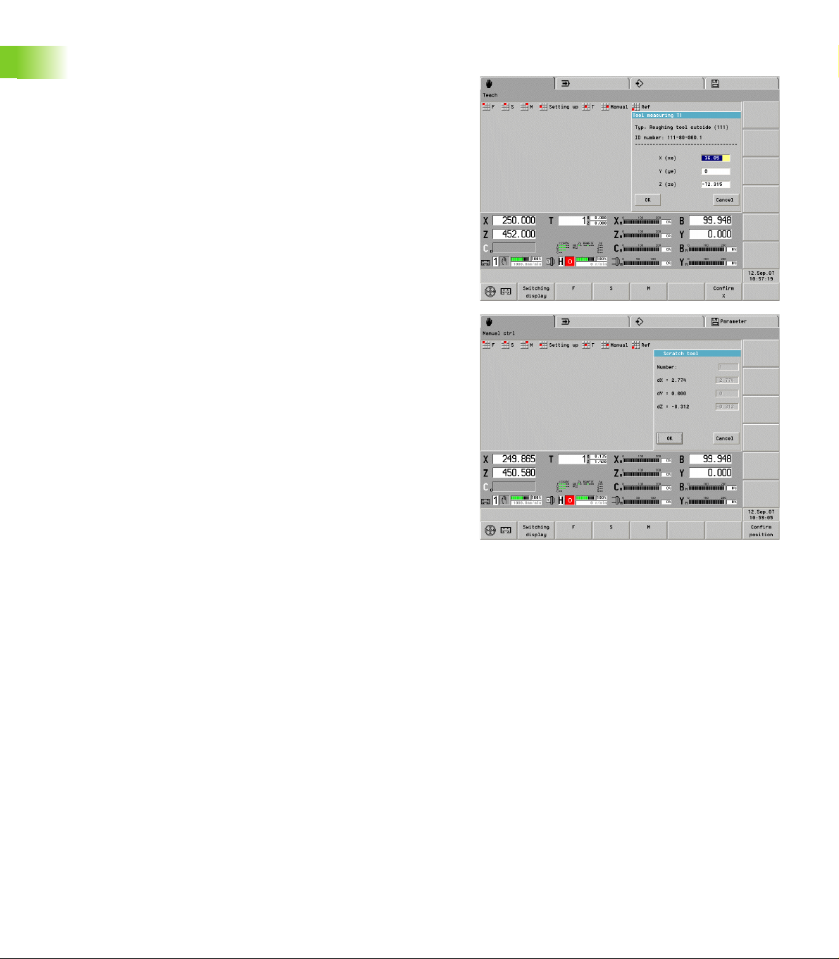
Measuring and compensating magazine tools
Measuring tools: The function determines the tool lengths
referenced to the current tilt angle of the B axis and the position angle
of the tool. These are the values that are indicated on the display. The
control additionally converts the measured data into dimensions
referenced to the position B=0 and saves them in the tool database.
U Select “Setting up > Tool set-up > Tool measuring” in
manual control mode. The control indicates the
current measurement values in the “Tool measuring
T...” dialog box.
U Measure and enter the tool dimensions and click OK
to close the dialog box.
The control
deletes the compensation values and
enters the tool dimensions in the database.
Determining compensation values: The compensation values are
determined and displayed referenced to the current tilt angle of the B
axis and the position angle of the tool. The control converts the
measured data into dimensions referenced to the position B=0 and
saves them in the tool database.
U Select “Setting up > Tool set-up > Tool
compensation” in manual control mode. In the
“Scratch tool” dialog box, the control indicates the
current compensation values referenced to position
1.2 Manual Control and Automatic Modes
B=0.
U Determine the compensation values and click OK to
close the dialog box.
The control applies the compensation values.
18
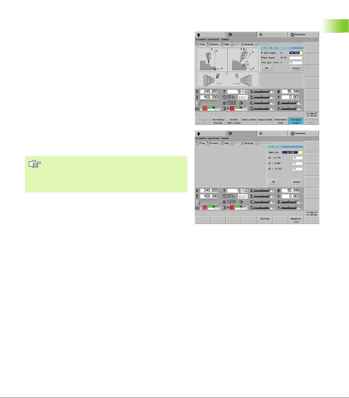
Tool compensation in automatic mode
Tool compensation: Determine the compensation values referenced
to the current tilt angle of the B axis and the position angle of the tool.
The control converts the measured data into dimensions referenced to
the position B=0 and saves them in the tool database.
U Select “Comp > Tool compensation” in automatic
mode. The control opens the “Tool correct.” dialog
box.
U Enter the parameters and click OK to close the dialog
box.
U In the “Tool correct.” dialog box, the control indicates
the compensation values referenced to the B axis
angle specified in the previous dialog box.
U Enter the new compensation values.
In the “T” box (machine display), the control indicates the
compensation values referenced to the current B axis angle and the
tool position angle.
The CNC PILOT saves the tool compensation data in the
tool database, together with the other tool data.
If the B axis is tilted, the CNC PILOT takes the tool
compensation data into account when calculating the
tool tip position.
Additive compensation values are independent of the tool data.
The compensation values are effective in the X, Y and Z directions.
Tilting the B axis has no influence on additive compensation values.
HEIDENHAIN CNC PILOT 4290 19
1.2 Manual Control and Automatic Modes
1.3 Programming Notes
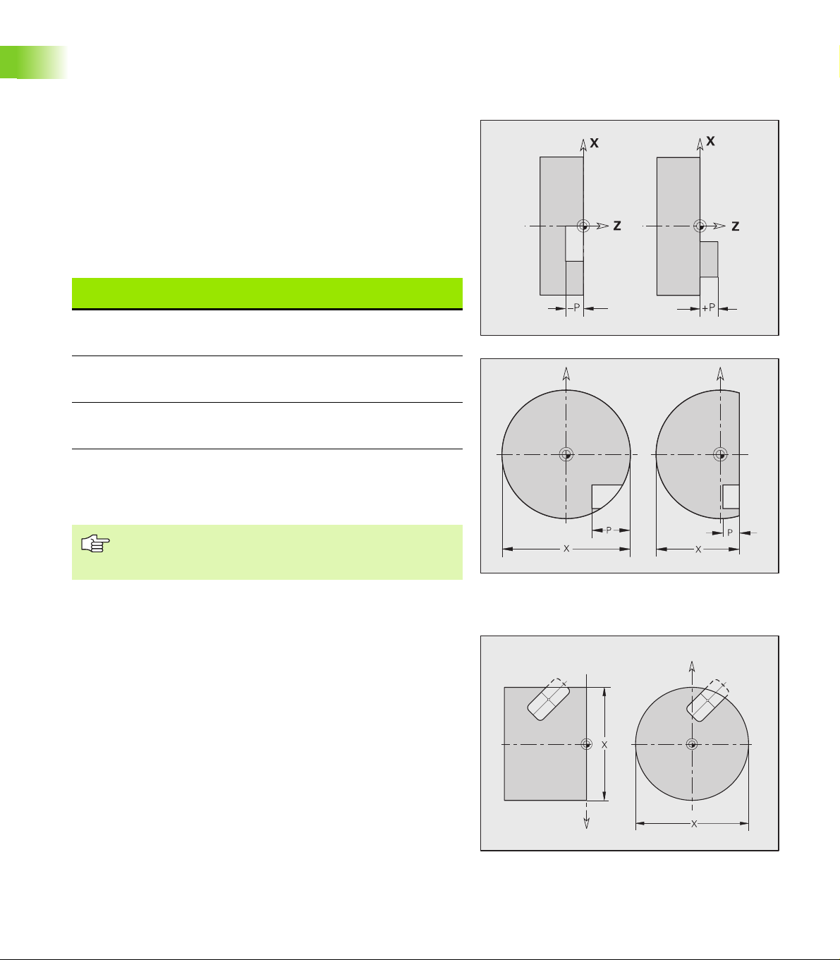
Milling contour position
Define the reference plane or the reference diameter in the section
code. Specify the depth and position of a milling contour (pocket,
island) in the contour definition:
With depth P programmed in the previous G308 cycle.
Alternatively on figures: Cycle parameter depth P.
The algebraic sign of “P” defines the position of the milling contour:
P<0: Pocket
P>0: Island
Milling contour position
1.3 Programming Notes
Section P Surface Milling floor
STIRN [FRONT] P<0
P>0
RUECKSEITE
[REAR SIDE]
P<0
P>0
Z
Z+P
Z
Z–P
Z+P
Z
Z–P
Z
MANTEL
[SURFACE]
X: Reference diameter from the section code
Z: Reference plane from the section code
P: Depth from G308 or from the figure definition
The area milling cycles mill the surface specified in the
contour definition. Islands within this surface are not
taken into consideration.
P<0
P>0
X
X+(P*2)
X+(P*2)
X
Cutting limit
If parts of the milling contour lie outside of the turning contour, you
must limit the machining area with the area diameter X / reference
diameter X (parameters of the section code or of the figure
definition).
The cutting limits are also effective when milling in a tilted plane.
20

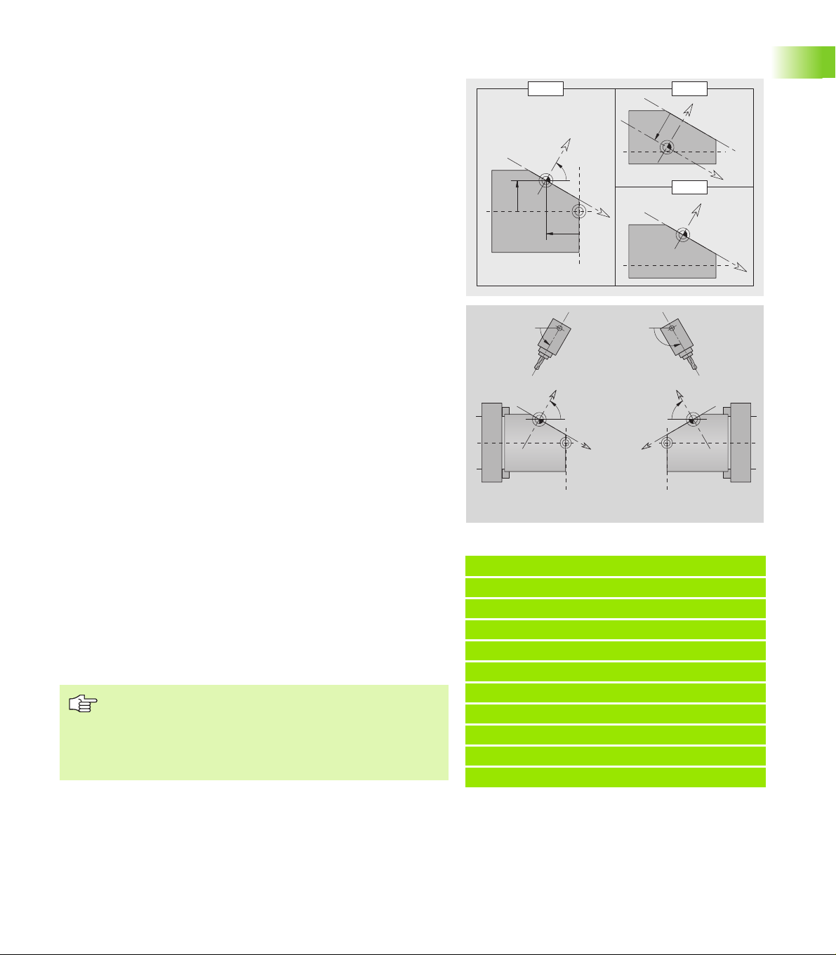
Drilling and milling in a tilted plane
HEIDENHAIN recommends tilting the coordinate system in such a
way that you can define the drilling patterns and milling contours in the
YZ plane. This has the advantage that you can then use all the contour,
figure and pattern definitions for the YZ plane.
The drilling and milling cycles themselves are executed in the tilted
plane. These cycles determine the position of the tilted plane from the
contour definitions.
It is also a good idea to tilt the B axis with G714 because this G
function includes the calculation of the tool position.
The following programming sequence is thus recommended:
Rotate and shift the coordinate system for the tilted plane with the
section code SURFACE_Y (see “SURFACE_Y section” on page 23).
Define the drilling patterns and milling contours in the YZ plane.
Position the B axis with G714.
Activate the YZ plane with G19.
Use the drilling and milling cycles for machining.
Alternatively, you can tilt the working plane with G16 and then execute
the machining operations in the tilted plane.
Please note that the tool orientation is not regenerated automatically
when you position the B axis with the single commands G0 or G15.
Program G712 to have the tool position recalculated.
1.3 Programming Notes
HEIDENHAIN CNC PILOT 4290 21
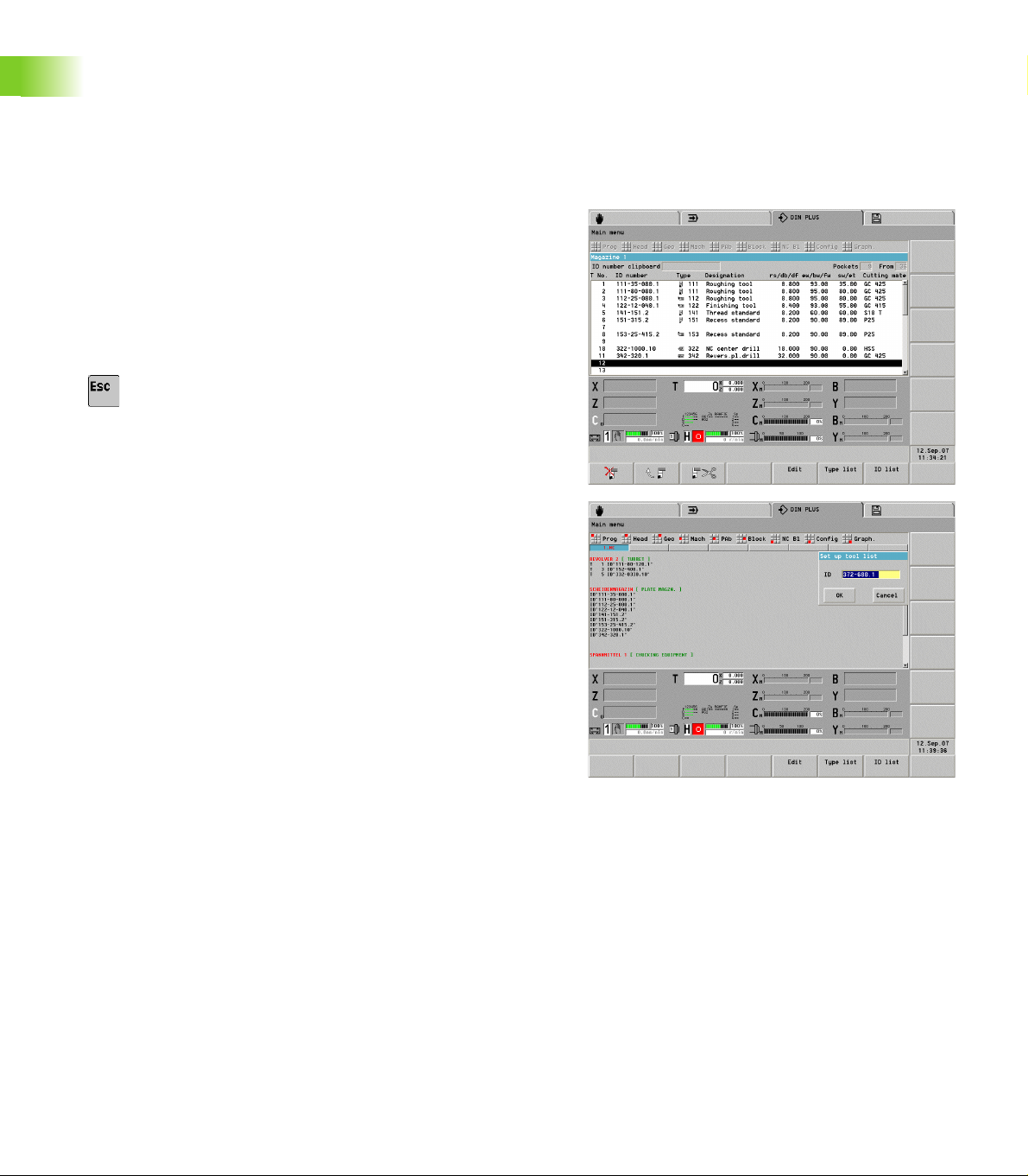
1.4 DIN PLUS: Section Codes
For lathes equipped with a tool magazine and/or a Y axis, the following
section codes are available.
PLATE MAGZN. section
In the PLATE MAGZN. section, you list all the tools that are used in the
NC program. This list is used when programming G714 (insert
magazine tool). The entries can be made in any order.
To create/edit the list of magazine tools:
U Select “Head > Set up tool list.”
U Select the tools from the database and enter them in
the list.
U Press the ESC key to conclude the list.
1.4 DIN PLUS: Section Codes
To enter or edit individual magazine tools:
U Position the cursor in the PLATE MAGZN. section.
U To enter a new tool: Press the INS key.
U To edit a tool: Press RETURN or double-click with the
left mouse button.
U Edit the “Set up tool list” dialog box.
FRONT_Y, REAR_SIDE_Y section
The section code identifies the XY plane (G17) and the reference plane
of the contour (Z direction).
Parameters
X Area diameter (as cutting limit)
Z Position of the reference plane—default: 0
C Spindle position—default: 0
22
SURFACE_Y section
X
H=0
B, I, K
K
I
Z
B
H=1
I
Z
B
X
Z
B
X
The section code identifies the YZ plane (G19). For machines equipped
with a B axis, it defines the tilted plane.
Without B axis: The reference diameter defines the contour position
in the X direction; the C axis angle defines the position on the
workpiece.
Parameters
X Reference diameter
C C axis angle—Defines the spindle position
With B axis (see figures): SURFACE_Y additionally performs the
following transformations and rotations for the tilted plane:
Shifts the coordinate system to the position I, K
Rotates the coordinate system by the angle B; reference point: I, K
H=0: Shifts the rotated coordinate system by –I. The coordinate
system is moved “back.”
Parameters
X Reference diameter
C C axis angle—Defines the spindle position
B Plane angle: Positive Z axis
I Plane reference in X direction (radius)
K Plane reference in Z direction
H Automatic shift of the coordinate system (default: 0)
0: The rotated coordinate system is shifted by –I
1: The coordinate system is not shifted
1.4 DIN PLUS: Section Codes
Shifting “back” coordinate system: The CNC PILOT evaluates the
reference diameter for the cutting limit. This value is also used as the
reference value for the depth that you program for drilling operations
and milling contours.
Since the reference diameter is referenced to the current zero point,
it is recommended when working in a tilted plane, to shift the rotated
coordinate system “back” by the distance –I. If the cutting limits are
not needed, for example for drilling holes, you can disable the shift of
the coordinate system (H=1) and set the reference diameter to 0.
Please note:
X is the infeed axis in a tilted coordinate system. X
coordinates are entered as diameter coordinates.
Mirroring the coordinate system has no effect on the
reference axis of the tilt angle (“B axis angle” of G714).
HEIDENHAIN CNC PILOT 4290 23
Example: “SURFACE_Y”
PROGRAMMKOPF [PROGRAM HEAD]
...
CONTOUR Q1 X0 Z600
ROHTEIL [BLANK]
...
FERTIGTEIL [FINISHED PART]
...
MANTEL_Y X118 C0 B130 I59 K0 [SURFACE_Y]
...
BEARBEITUNG [MACHINING]
...
1.5 DIN PLUS: Contours in the XY
Plane
Starting point of contour G170 Geo
G170 defines the starting point of a contour in the XY plane.
Parameters
X Starting point of contour (radius)
Y Starting point of contour
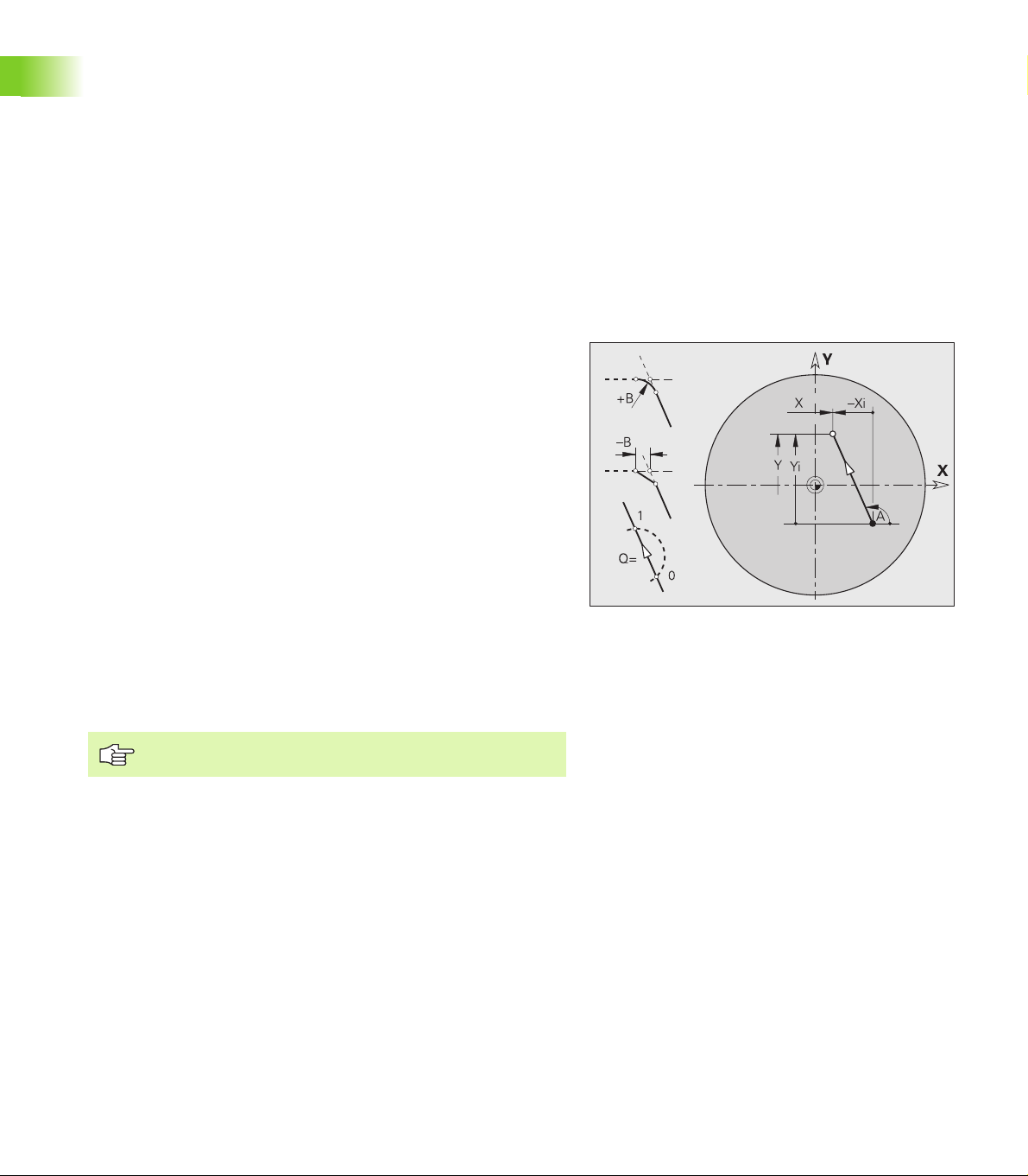
Linear element G171 Geo
G171 defines a line segment in a contour of the XY plane.
Parameters
X End point (radius)
Y End point
A Angle to positive X axis
B Chamfer/rounding. Defines the transition to the next contour
element. When entering a chamfer/rounding, program the
theoretical end point.
No entry: Tangential transition
1.5 DIN PLUS: Contours in the XY Plane
B=0: No tangential transition
B>0: Rounding radius
B<0: Chamfer width
Q Point of intersection. End point if the line segment intersects
a circular arc (default: 0):
Q=0: Near point of intersection
Q=1: Far point of intersection
Programming X, Y: Absolute, incremental, modal or “?”
24
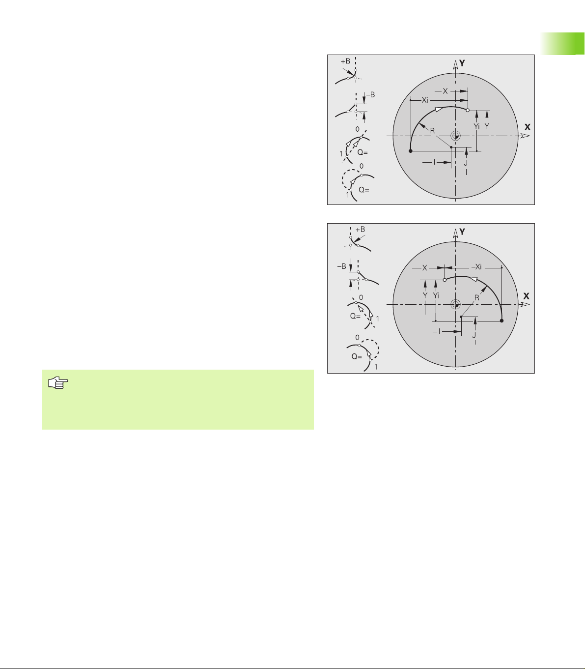
Circular arc G172/G173 Geo
G172/G173 defines a circular arc in a contour of the XY plane. Direction
of rotation: See help graphic
Parameters
X End point (radius)
Y End point
I Center in X direction (radius)
J Center in Y direction
R Radius
B Chamfer/rounding. Defines the transition to the next contour
element. When entering a chamfer/rounding, program the
theoretical end point.
No entry: Tangential transition
B=0: No tangential transition
B>0: Rounding radius
B<0: Chamfer width
Q Point of intersection. End point if the line segment intersects
a circular arc (default: 0):
For a transition to a line segment:
Q=0: Near point of intersection
Q=1: Far point of intersection
For a transition to a circular arc:
Q=0: Far point of intersection
Q=1: Near point of intersection
1.5 DIN PLUS: Contours in the XY Plane
Programming
X, Y: Absolute, incremental, modal or “?”
I, J: Absolute or incremental
End point must not be the starting point (no full circle).
HEIDENHAIN CNC PILOT 4290 25
Hole G370 Geo
G370 defines a hole with countersinking and thread in the XY plane.
Parameters
X Center of hole (radius)
Y Center of hole
B Hole diameter
P Depth of hole (excluding point)
W Point angle (default: 180°)
R Sinking diameter
U Sinking depth
E Sinking angle
I Thread diameter
J Thread depth
K Thread runout length
F Thread pitch
V Left-hand or right-hand thread (default: 0)
V=0: Right-hand thread
V=1: Left-hand thread
A Angle to Z axis – inclination of the hole
1.5 DIN PLUS: Contours in the XY Plane
Front face (range: –90° < A < 90°)—default: 0°
Rear side (range: 90° < A < 270°)—default: 180°
O Centering diameter
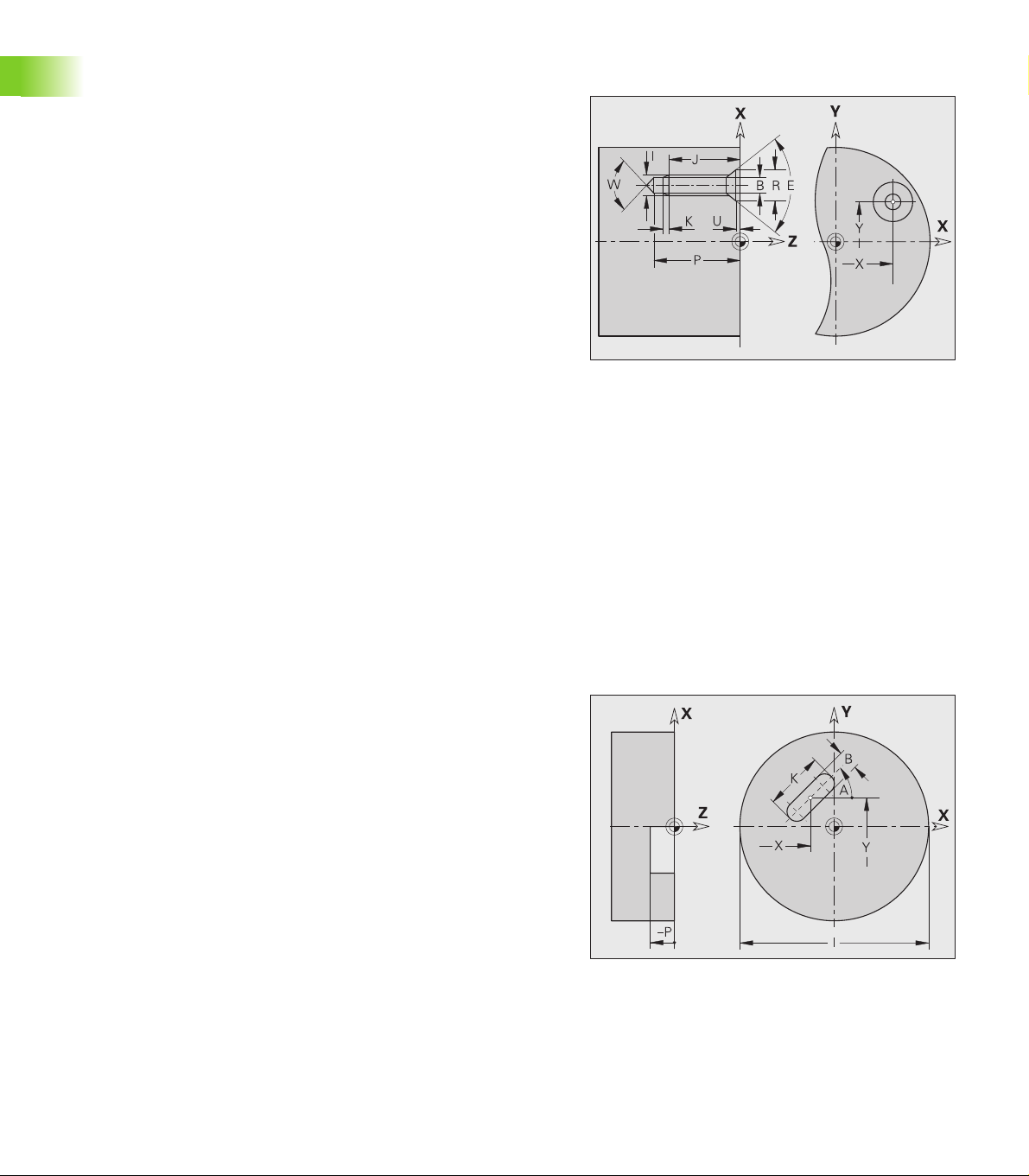
Linear slot G371 Geo
G371 defines the contour of a linear slot in the XY plane.
Parameters
X Center of slot (radius)
Y Center of slot
K Slot length
BSlot width
A Angle of slot length (reference: positive X axis)—default: 0°
P Depth/height (default: “P” from G308)
P<0: Pocket
P>0: Island
I Area diameter (as cutting limit)
No entry: “X” from section code
“I” overwrites “X” from section code
26
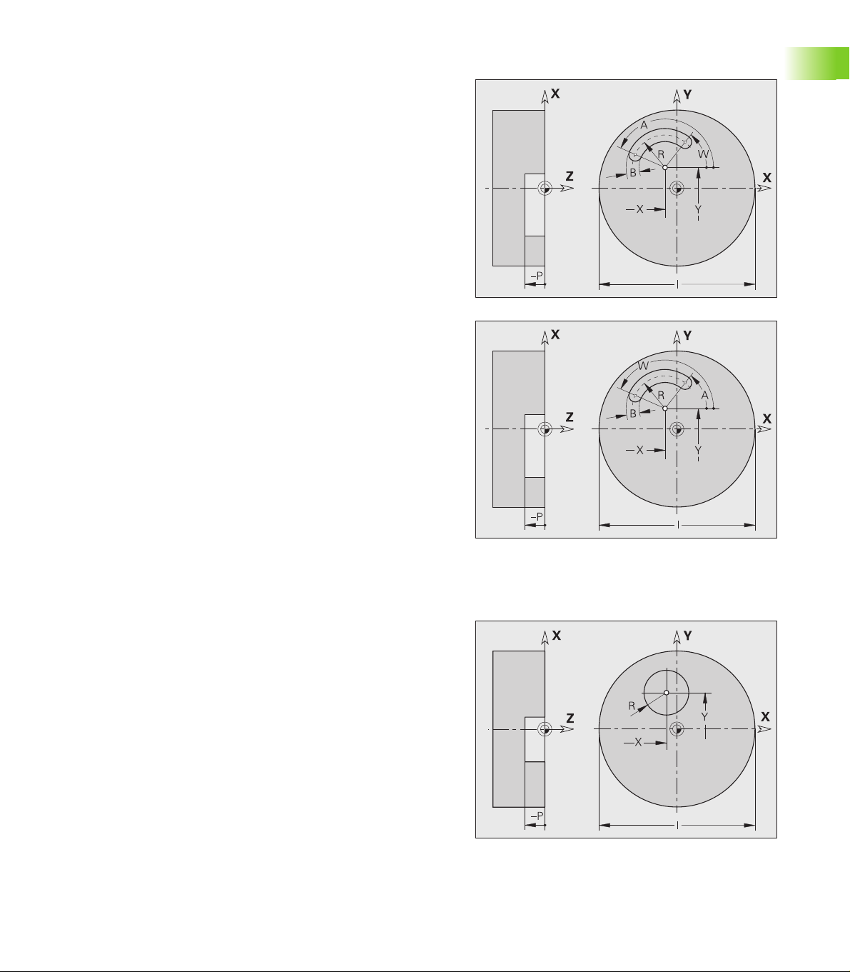
Circular slot G372/G373 Geo
G372/G373 defines a circular slot in the XY plane.
G372: Circular slot clockwise
G373: Circular slot counterclockwise
Parameters
X Center of slot curvature (radius)
Y Center of slot curvature
R Curvature radius (reference: center point path of the slot)
A Starting angle; reference: positive X axis (default: 0°)
W End angle; reference: positive X axis (default: 0°)
B Slot width
P Depth/height (default: “P” from G308)
P<0: Pocket
P>0: Island
I Area diameter (as cutting limit)
No entry: “X” from section code
“I” overwrites “X” from section code
Full circle G374 Geo
G374 defines a full circle in the XY plane.
Parameters
X Circle center (radius)
Y Circle center
R Circle radius
P Depth/height (default: “P” from G308)
P<0: Pocket
P>0: Island
I Area diameter (as cutting limit)
No entry: “X” from section code
“I” overwrites “X” from section code
1.5 DIN PLUS: Contours in the XY Plane
HEIDENHAIN CNC PILOT 4290 27
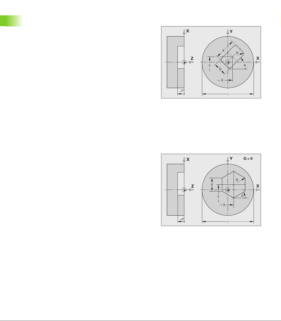
Rectangle G375 Geo
G375 defines a rectangle in the XY plane.
Parameters
X Center of rectangle (radius)
Y Center of rectangle
K Length of rectangle
B (Height) width of rectangle
R Chamfer/rounding (default: 0)
R>0: Radius of rounding arc
R<0: Chamfer width
A Angle to X axis (default: 0°)
P Depth/height (default: “P” from G308)
P<0: Pocket
P>0: Island
I Area diameter (as cutting limit)
No entry: “X” from section code
“I” overwrites “X” from section code
Eccentric polygon G377 Geo
G377 defines the contour of an eccentric polygon in the XY plane.
1.5 DIN PLUS: Contours in the XY Plane
Parameters
X Center point of polygon (radius)
Y Center point of polygon
Q Number of edges (Q >= 3)
A Angle to X axis (default: 0°)
K Edge length
K>0: Edge length
K<0: Inside diameter
R Chamfer/rounding—default: 0
R>0: Radius of rounding arc
R<0: Chamfer width
P Depth/height (default: “P” from G308)
P<0: Pocket
P>0: Island
I Area diameter (as cutting limit)
No entry: “X” from section code
“I” overwrites “X” from section code
28
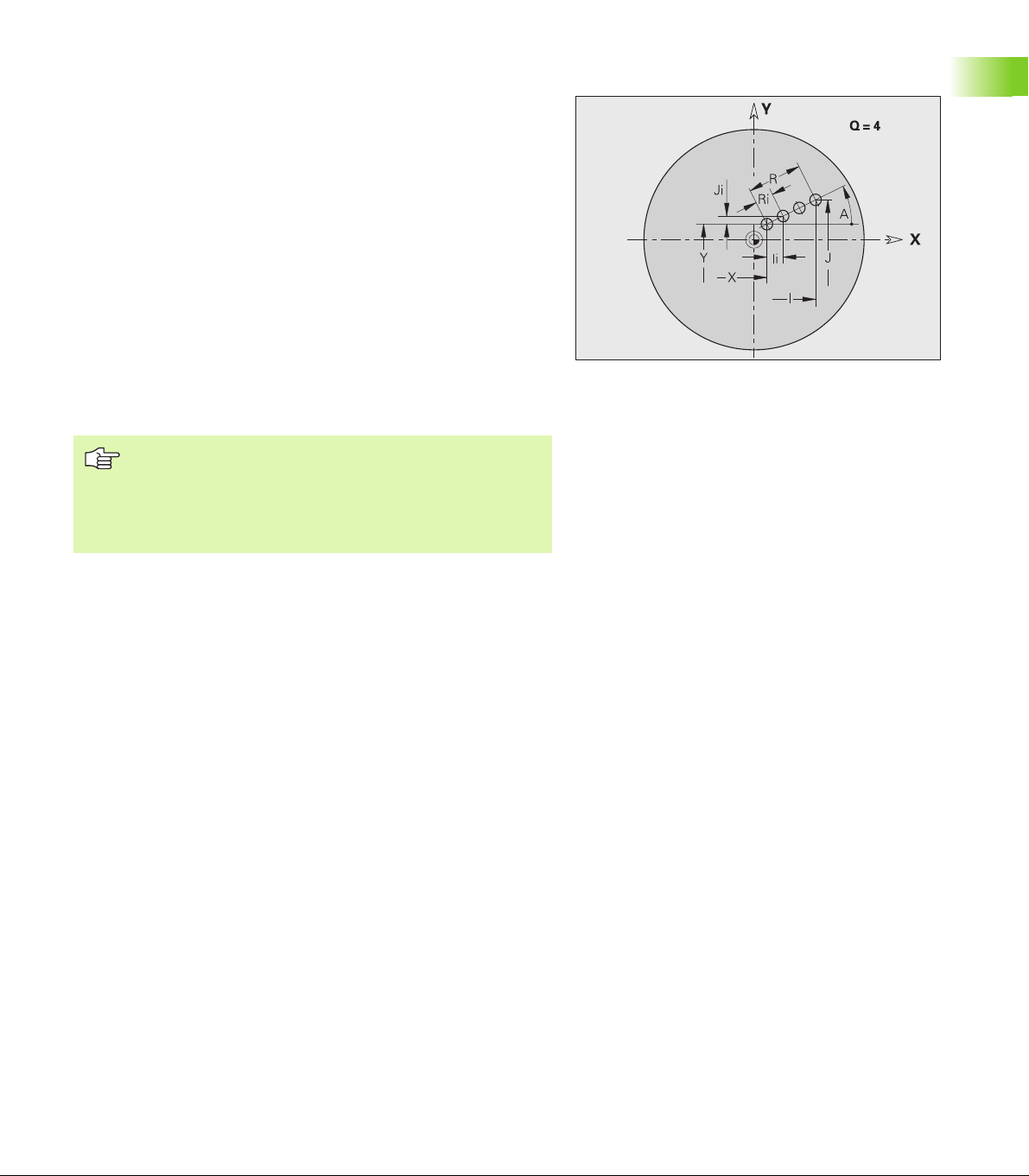
Linear pattern in XY plane, G471-Geo
G471 defines a linear pattern in the XY plane. G471 affects the hole or
figure defined in the following block (G370 to G375, G377).
Parameters
Q Number of figures
X Starting point of pattern (radius)
Y Starting point of pattern
I End point of pattern (X direction; radius)
J End point of pattern (Y direction)
Ii Distance in X direction between two figures
Ji Distance in Y direction between two figures
A Angle of longitudinal axis to X axis
R Total length of pattern
Ri Distance between two figures (pattern distance)
Programming notes
Program the hole/figure in the following block without a
center.
The milling cycle (MACHINING section) calls the hole/
figure in the following block - not the pattern definition.
1.5 DIN PLUS: Contours in the XY Plane
HEIDENHAIN CNC PILOT 4290 29
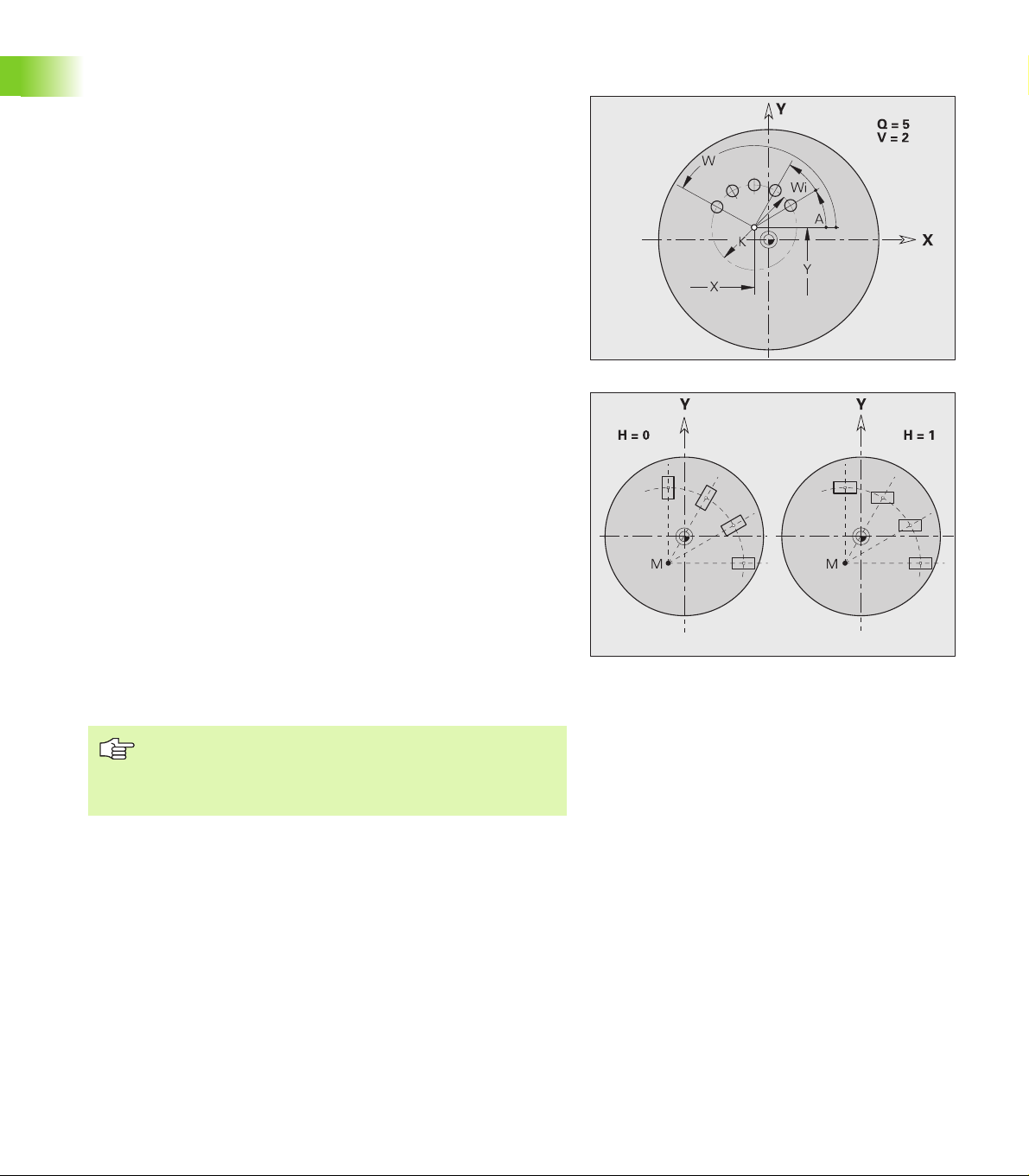
Circular pattern in XY plane, G472 Geo
G472 defines a circular pattern in the XY plane. G472 is effective for
the figure defined in the following block (G370 to G375, G377).
Parameters
Q Number of figures
K Pattern diameter
A Starting angle—position of the first figure; reference: positive
X axis (default: 0°)
W End angle—position of the last figure; reference: positive X
axis; (default: 360°)
Wi Angle between two figures
V Direction—orientation (default: 0)
V=0, without W: Figures are arranged on a full circle
V=0, with W: Figures are arranged on the longer circular arc
V=0, with Wi: The algebraic sign of Wi defines the direction
(Wi<0: clockwise)
V=1, with W: Clockwise
V=1, with Wi: Clockwise (algebraic sign of Wi has no effect)
V=2, with W: Counterclockwise
V=2, with Wi: Counterclockwise (algebraic sign of Wi has
no effect)
X Center of pattern (radius)
1.5 DIN PLUS: Contours in the XY Plane
Y Center of pattern
H Position of the figures (default: 0)
H=0: Normal position; the figures are rotated about the
circle center (rotation)
H=1: Original position; the position of the figures relative to
the coordinate system remains unchanged (translation)
Program the hole/figure in the following block without a
center. Exception: circular slot.
The milling cycle (MACHINING section) calls the hole/
figure in the following block—not the pattern definition.
30
Loading...