


 Loading...
WebUIReferenceGuide
ProductModel:xStack® DES-3528/DES-3552Series
Layer2ManagedStackableFastEthernetSwitch
Release2.6
September 2010

xStack® DES-3528/DES-3552 Series Layer 2 Stackable Fast Ethernet Managed Switch Web UI Reference Guide
Information in this document is subject to change without notice. © 2010 D-Link Corporation. All rights reserved.
Reproduction of this document in any manner whatsoever without the written permission of D-Link Corporation is strictly forbidden.
Trademarks used in this text: D-Link and the D-LINK logo are trademarks of D-Link Corporation; Microsoft and Windows are registered trademarks of Microsoft Corporation.
Other trademarks and trade names may be used in this document to refer to either the entities claiming the marks and names or their products. D-Link Corporation disclaims any proprietary interest in trademarks and trade names other than its own.
September 2010 P/N 651ES3500065G
i

xStack® DES-3528/DES-3552 Series Layer 2 Stackable Fast Ethernet Managed Switch Web UI Reference Guide
|
Table of Contents |
|
Intended Readers ............................................................................................................................. |
1 |
|
Typographical Conventions............................................................................................................................................. |
1 |
|
Notes, Notices and Cautions........................................................................................................................................... |
1 |
|
Chapter 1 |
Web-based Switch Configuration............................................................................... |
2 |
Introduction...................................................................................................................................................................... |
|
2 |
Login to the Web Manager.............................................................................................................................................. |
2 |
|
Web-based User Interface .............................................................................................................................................. |
3 |
|
Areas of the User Interface.......................................................................................................................................... |
3 |
|
Web Pages...................................................................................................................................................................... |
|
4 |
Chapter 2 |
System Configuration................................................................................................. |
5 |
Device Information .......................................................................................................................................................... |
5 |
|
System Information Settings ........................................................................................................................................... |
6 |
|
Dual Configuration Settings ............................................................................................................................................ |
7 |
|
Firmware Information Settings ........................................................................................................................................ |
8 |
|
Port Configuration ........................................................................................................................................................... |
9 |
|
Port Settings ................................................................................................................................................................ |
9 |
|
Port Description Settings ........................................................................................................................................... |
10 |
|
Port Error Disabled .................................................................................................................................................... |
11 |
|
Jumbo Frame Settings .............................................................................................................................................. |
12 |
|
PoE................................................................................................................................................................................ |
|
12 |
PoE System Settings................................................................................................................................................. |
13 |
|
PoE Port Settings ...................................................................................................................................................... |
14 |
|
Serial Port Settings ....................................................................................................................................................... |
15 |
|
System Log configuration.............................................................................................................................................. |
16 |
|
System Log Settings.................................................................................................................................................. |
16 |
|
System Log Server Settings ...................................................................................................................................... |
17 |
|
System Log................................................................................................................................................................ |
|
17 |
System Log & Trap Settings...................................................................................................................................... |
18 |
|
System Severity Settings........................................................................................................................................... |
19 |
|
Time Range Settings..................................................................................................................................................... |
20 |
|
Time Settings ................................................................................................................................................................ |
|
20 |
User Accounts Settings................................................................................................................................................. |
21 |
|
Stacking......................................................................................................................................................................... |
|
22 |
Stacking Device Table............................................................................................................................................... |
24 |
|
Stacking Mode Settings............................................................................................................................................. |
25 |
|
Chapter 3 |
Management ............................................................................................................ |
26 |
ARP ............................................................................................................................................................................... |
|
26 |
Static ARP Settings ................................................................................................................................................... |
26 |
|
Proxy ARP Settings ................................................................................................................................................... |
27 |
|
ARP Table ................................................................................................................................................................. |
|
27 |
Gratuitous ARP ............................................................................................................................................................. |
28 |
|
Gratuitous ARP Global Settings ................................................................................................................................ |
28 |
|
Gratuitous ARP Settings............................................................................................................................................ |
29 |
|
|
ii |
|

xStack® DES-3528/DES-3552 Series Layer 2 Stackable Fast Ethernet Managed Switch Web UI Reference Guide
IPv6 Neighbor Settings ................................................................................................................................................. |
29 |
|
IP Interface.................................................................................................................................................................... |
|
30 |
System IP Address Settings ...................................................................................................................................... |
30 |
|
Interface Settings....................................................................................................................................................... |
31 |
|
Management Settings ................................................................................................................................................... |
34 |
|
Session Table................................................................................................................................................................ |
|
35 |
Single IP Management.................................................................................................................................................. |
35 |
|
Single IP Settings ...................................................................................................................................................... |
37 |
|
Topology.................................................................................................................................................................... |
|
38 |
Firmware Upgrade..................................................................................................................................................... |
44 |
|
Configuration File Backup/Restore............................................................................................................................ |
44 |
|
Upload Log File ......................................................................................................................................................... |
45 |
|
SNMP Settings.............................................................................................................................................................. |
45 |
|
SNMP Global Settings............................................................................................................................................... |
46 |
|
SNMP Traps Settings ................................................................................................................................................ |
47 |
|
SNMP Linkchange Traps Settings ............................................................................................................................ |
47 |
|
SNMP View Table Settings ....................................................................................................................................... |
48 |
|
SNMP Community Table Settings............................................................................................................................. |
49 |
|
SNMP Group Table Settings ..................................................................................................................................... |
50 |
|
SNMP Engine ID Settings ......................................................................................................................................... |
51 |
|
SNMP User Table Settings........................................................................................................................................ |
52 |
|
SNMP Host Table Settings........................................................................................................................................ |
53 |
|
SNMPv6 Host Table Settings.................................................................................................................................... |
53 |
|
RMON Settings.......................................................................................................................................................... |
54 |
|
Telnet Settings |
.............................................................................................................................................................. |
55 |
Web Settings................................................................................................................................................................. |
|
55 |
Chapter 4 |
L2 Features.............................................................................................................. |
56 |
VLAN ............................................................................................................................................................................. |
|
56 |
802.1Q VLAN Settings .............................................................................................................................................. |
61 |
|
802.1v Protocol VLAN ............................................................................................................................................... |
64 |
|
Asymmetric VLAN Settings ....................................................................................................................................... |
66 |
|
GVRP......................................................................................................................................................................... |
|
66 |
MAC-based VLAN Settings ....................................................................................................................................... |
69 |
|
PVID Auto Assign Settings........................................................................................................................................ |
69 |
|
Subnet VLAN............................................................................................................................................................. |
70 |
|
VLAN Counter Settings ............................................................................................................................................. |
72 |
|
Voice VLAN ............................................................................................................................................................... |
|
73 |
VLAN Trunk Settings ................................................................................................................................................. |
77 |
|
Browse VLAN ............................................................................................................................................................ |
78 |
|
Show VLAN Ports...................................................................................................................................................... |
78 |
|
Q-in-Q............................................................................................................................................................................ |
|
79 |
Q-in-Q Settings.......................................................................................................................................................... |
79 |
|
VLAN Translation Settings ........................................................................................................................................ |
80 |
|
Layer 2 Protocol Tunneling Settings ............................................................................................................................. |
81 |
|
Spanning Tree............................................................................................................................................................... |
|
82 |
STP Bridge Global Settings....................................................................................................................................... |
85 |
|
STP Port Settings ...................................................................................................................................................... |
86 |
|
|
|
iii |

xStack® DES-3528/DES-3552 Series Layer 2 Stackable Fast Ethernet Managed Switch Web UI Reference Guide
MST Configuration Identification ............................................................................................................................... |
87 |
|
STP Instance Settings ............................................................................................................................................... |
88 |
|
MSTP Port Information .............................................................................................................................................. |
89 |
|
Link Aggregation ........................................................................................................................................................... |
91 |
|
Port Trunking Settings ............................................................................................................................................... |
92 |
|
LACP Port Settings.................................................................................................................................................... |
93 |
|
FDB ............................................................................................................................................................................... |
|
94 |
Static FDB Settings ................................................................................................................................................... |
94 |
|
MAC Notification Settings.......................................................................................................................................... |
95 |
|
MAC Address Aging Time Settings ........................................................................................................................... |
96 |
|
MAC Address Table .................................................................................................................................................. |
97 |
|
ARP & FDB Table...................................................................................................................................................... |
98 |
|
L2 Multicast Control ...................................................................................................................................................... |
98 |
|
IGMP Snooping ......................................................................................................................................................... |
98 |
|
MLD Snooping......................................................................................................................................................... |
107 |
|
Multicast VLAN ........................................................................................................................................................ |
116 |
|
Multicast Filtering ........................................................................................................................................................ |
123 |
|
IPv4 Multicast Filtering ............................................................................................................................................ |
123 |
|
Multicast Filtering Mode........................................................................................................................................... |
126 |
|
ERPS Settings............................................................................................................................................................. |
|
127 |
LLDP ........................................................................................................................................................................... |
|
130 |
LLDP Global Settings .............................................................................................................................................. |
130 |
|
LLDP Port Settings .................................................................................................................................................. |
131 |
|
LLDP Management Address List............................................................................................................................. |
133 |
|
LLDP Basic TLVs Settings ...................................................................................................................................... |
133 |
|
LLDP Dot1 TLVs Settings........................................................................................................................................ |
134 |
|
LLDP Dot3 TLVs Settings........................................................................................................................................ |
136 |
|
LLDP Statistic System ............................................................................................................................................. |
137 |
|
LLDP Local Port Information ................................................................................................................................... |
137 |
|
LLDP Remote Port Information ............................................................................................................................... |
139 |
|
Chapter 5 |
L3 Features............................................................................................................ |
140 |
Local Route Settings ................................................................................................................................................... |
140 |
|
IPv4 Static/Default Route Settings.............................................................................................................................. |
140 |
|
IPv4 Route Table ........................................................................................................................................................ |
141 |
|
IPv6 Static/Default Route Settings.............................................................................................................................. |
142 |
|
IPv6 Route Table ........................................................................................................................................................ |
142 |
|
Policy Route Settings .................................................................................................................................................. |
143 |
|
IP Forwarding Table.................................................................................................................................................... |
144 |
|
Chapter 6 |
QoS........................................................................................................................ |
145 |
802.1p Settings ........................................................................................................................................................... |
147 |
|
802.1p Default Priority Settings............................................................................................................................... |
147 |
|
802.1p User Priority Settings................................................................................................................................... |
148 |
|
802.1p Map Settings................................................................................................................................................ |
149 |
|
Bandwidth Control....................................................................................................................................................... |
150 |
|
Bandwidth Control Settings ..................................................................................................................................... |
150 |
|
Queue Bandwidth Control Settings ......................................................................................................................... |
151 |
|
Traffic Control Settings................................................................................................................................................ |
152 |
|
|
|
iv |

xStack® DES-3528/DES-3552 Series Layer 2 Stackable Fast Ethernet Managed Switch Web UI Reference Guide
DSCP .......................................................................................................................................................................... |
|
155 |
DSCP Trust Settings ............................................................................................................................................... |
155 |
|
DSCP Map Settings................................................................................................................................................. |
156 |
|
HOL Blocking Prevention ............................................................................................................................................ |
158 |
|
Scheduling Settings .................................................................................................................................................... |
159 |
|
QoS Scheduling....................................................................................................................................................... |
159 |
|
QoS Scheduling Mechanism ................................................................................................................................... |
160 |
|
SRED .......................................................................................................................................................................... |
|
162 |
SRED Settings......................................................................................................................................................... |
162 |
|
SRED Drop Counter ................................................................................................................................................ |
164 |
|
Chapter 7 |
ACL ........................................................................................................................ |
165 |
ACL Configuration Wizard........................................................................................................................................... |
165 |
|
Access Profile List....................................................................................................................................................... |
166 |
|
Add an Ethernet ACL Profile ................................................................................................................................... |
167 |
|
Adding an IPv4 ACL Profile ..................................................................................................................................... |
171 |
|
Adding an IPv6 ACL Profile ..................................................................................................................................... |
176 |
|
Adding a Packet Content ACL Profile ..................................................................................................................... |
179 |
|
CPU Access Profile List .............................................................................................................................................. |
184 |
|
Adding a CPU Ethernet ACL Profile........................................................................................................................ |
185 |
|
Adding a CPU IPv4 ACL Profile .............................................................................................................................. |
188 |
|
Adding a CPU IPv6 ACL Profile .............................................................................................................................. |
192 |
|
Adding a CPU Packet Content ACL Profile............................................................................................................. |
195 |
|
ACL Finder .................................................................................................................................................................. |
|
198 |
ACL Flow Meter........................................................................................................................................................... |
199 |
|
Chapter 8 |
Security .................................................................................................................. |
202 |
802.1X ......................................................................................................................................................................... |
|
202 |
802.1X Global Settings............................................................................................................................................ |
205 |
|
802.1X Port Settings................................................................................................................................................ |
206 |
|
802.1X User Settings............................................................................................................................................... |
207 |
|
Guest VLAN Settings............................................................................................................................................... |
208 |
|
Authenticator State .................................................................................................................................................. |
209 |
|
Authenticator Statistics ............................................................................................................................................ |
210 |
|
Authenticator Session Statistics .............................................................................................................................. |
211 |
|
Authenticator Diagnostics........................................................................................................................................ |
212 |
|
Initialize Port(s)........................................................................................................................................................ |
213 |
|
Reauthenticate Port(s)............................................................................................................................................. |
214 |
|
RADIUS....................................................................................................................................................................... |
|
215 |
Authentication RADIUS Server Settings ................................................................................................................. |
215 |
|
RADIUS Accounting Settings .................................................................................................................................. |
216 |
|
RADIUS Authentication ........................................................................................................................................... |
216 |
|
RADIUS Account Client........................................................................................................................................... |
218 |
|
IP-MAC-Port Binding (IMPB)....................................................................................................................................... |
220 |
|
IMPB Global Settings .............................................................................................................................................. |
220 |
|
IMPB Port Settings .................................................................................................................................................. |
221 |
|
IMPB Entry Settings ................................................................................................................................................ |
222 |
|
MAC Block List ........................................................................................................................................................ |
223 |
|
DHCP Snooping ...................................................................................................................................................... |
223 |
|
|
|
v |

xStack® DES-3528/DES-3552 Series Layer 2 Stackable Fast Ethernet Managed Switch Web UI Reference Guide
ND Snooping ........................................................................................................................................................... |
225 |
MAC-based Access Control (MAC)............................................................................................................................. |
227 |
MAC-based Access Control Settings ...................................................................................................................... |
227 |
MAC-based Access Control Local Settings............................................................................................................. |
229 |
MAC-based Access Control Authentication State................................................................................................... |
230 |
Web-based Access Control (WAC)............................................................................................................................. |
231 |
WAC Global Settings............................................................................................................................................... |
233 |
WAC User Settings.................................................................................................................................................. |
234 |
WAC Port Settings................................................................................................................................................... |
235 |
WAC Authentication State....................................................................................................................................... |
236 |
Japanese Web-based Access Control (JWAC) .......................................................................................................... |
236 |
JWAC Global Settings ............................................................................................................................................. |
236 |
JWAC Port Settings................................................................................................................................................. |
238 |
JWAC User Settings................................................................................................................................................ |
240 |
JWAC Authentication State ..................................................................................................................................... |
240 |
JWAC Customize Page Language.......................................................................................................................... |
241 |
JWAC Customize Page ........................................................................................................................................... |
242 |
Compound Authentication........................................................................................................................................... |
243 |
Compound Authentication Settings ......................................................................................................................... |
244 |
Compound Authentication Guest VLAN Settings.................................................................................................... |
246 |
Port Security................................................................................................................................................................ |
247 |
Port Security Settings .............................................................................................................................................. |
247 |
Port Security VLAN Settings.................................................................................................................................... |
248 |
Port Security Entries................................................................................................................................................ |
249 |
ARP Spoofing Prevention Settings ............................................................................................................................. |
249 |
BPDU Attack Protection .............................................................................................................................................. |
250 |
Loopback Detection Settings ...................................................................................................................................... |
252 |
Traffic Segmentation Settings..................................................................................................................................... |
253 |
NetBIOS Filtering Settings .......................................................................................................................................... |
254 |
DHCP Server Screening ............................................................................................................................................. |
255 |
DHCP Server Screening Port Settings.................................................................................................................... |
255 |
DHCP Offer Permit Entry Settings........................................................................................................................... |
256 |
Access Authentication Control .................................................................................................................................... |
256 |
Enable Admin .......................................................................................................................................................... |
257 |
Authentication Policy Settings ................................................................................................................................. |
258 |
Application Authentication Settings ......................................................................................................................... |
259 |
Authentication Server Group Settings ..................................................................................................................... |
259 |
Authentication Server Settings ................................................................................................................................ |
261 |
Login Method Lists Settings .................................................................................................................................... |
262 |
Enable Method Lists Settings.................................................................................................................................. |
263 |
Local Enable Password Settings............................................................................................................................. |
264 |
SSL Settings................................................................................................................................................................ |
265 |
SSH ............................................................................................................................................................................. |
267 |
SSH Settings ........................................................................................................................................................... |
267 |
SSH Authentication Method and Algorithm Settings............................................................................................... |
268 |
SSH User Authentication List .................................................................................................................................. |
270 |
Trusted Host Settings.................................................................................................................................................. |
271 |
|
vi |

xStack® DES-3528/DES-3552 Series Layer 2 Stackable Fast Ethernet Managed Switch Web UI Reference Guide
Safeguard Engine Settings ......................................................................................................................................... |
272 |
|
Chapter 9 |
Network Application ............................................................................................... |
275 |
DHCP .......................................................................................................................................................................... |
|
275 |
DHCP Relay |
............................................................................................................................................................ |
275 |
DHCP Server........................................................................................................................................................... |
281 |
|
DHCPv6 Relay ........................................................................................................................................................ |
285 |
|
DHCP Local Relay Settings..................................................................................................................................... |
287 |
|
DNS............................................................................................................................................................................. |
|
287 |
DNS Relay............................................................................................................................................................... |
|
287 |
PPPoE Circuit ID Insertion Settings............................................................................................................................ |
289 |
|
SNTP........................................................................................................................................................................... |
|
290 |
SNTP Settings ......................................................................................................................................................... |
290 |
|
Time Zone Settings ................................................................................................................................................. |
291 |
|
Chapter 10 |
OAM....................................................................................................................... |
293 |
CFM............................................................................................................................................................................. |
|
293 |
CFM Settings........................................................................................................................................................... |
293 |
|
CFM Port Settings ................................................................................................................................................... |
298 |
|
CFM Loopback Settings .......................................................................................................................................... |
299 |
|
CFM Linktrace Settings ........................................................................................................................................... |
300 |
|
CFM Packet Counter ............................................................................................................................................... |
300 |
|
CFM Fault Table...................................................................................................................................................... |
301 |
|
CFM MP Table ........................................................................................................................................................ |
302 |
|
Ethernet OAM.............................................................................................................................................................. |
|
302 |
Ethernet OAM Settings............................................................................................................................................ |
302 |
|
Ethernet OAM Configuration Settings ..................................................................................................................... |
303 |
|
Ethernet OAM Event Log......................................................................................................................................... |
305 |
|
Ethernet OAM Statistics .......................................................................................................................................... |
305 |
|
DULD Settings............................................................................................................................................................. |
|
306 |
Cable Diagnostics ....................................................................................................................................................... |
307 |
|
Chapter 11 |
Monitoring .............................................................................................................. |
309 |
Utilization..................................................................................................................................................................... |
|
309 |
CPU Utilization......................................................................................................................................................... |
309 |
|
DRAM & Flash Utilization ........................................................................................................................................ |
310 |
|
Port Utilization ......................................................................................................................................................... |
310 |
|
Statistics ...................................................................................................................................................................... |
|
311 |
Port Statistics........................................................................................................................................................... |
311 |
|
Packet Size.............................................................................................................................................................. |
|
320 |
VLAN Counter Statistics .......................................................................................................................................... |
322 |
|
Mirror ........................................................................................................................................................................... |
|
323 |
Port Mirror Settings.................................................................................................................................................. |
323 |
|
RSPAN Settings ...................................................................................................................................................... |
324 |
|
sFlow ........................................................................................................................................................................... |
|
325 |
sFlow Global Settings.............................................................................................................................................. |
325 |
|
sFlow Analyzer Server Settings............................................................................................................................... |
326 |
|
sFlow Flow Sampler Settings .................................................................................................................................. |
326 |
|
sFlow Counter Poller Settings ................................................................................................................................. |
327 |
|
|
|
vii |

xStack® DES-3528/DES-3552 Series Layer 2 Stackable Fast Ethernet Managed Switch Web UI Reference Guide
Ping Test ..................................................................................................................................................................... |
328 |
Trace Route................................................................................................................................................................. |
329 |
Peripheral.................................................................................................................................................................... |
331 |
Device Status........................................................................................................................................................... |
331 |
Chapter 12 Save and Tools ...................................................................................................... |
332 |
Save Configuration ID 1 .............................................................................................................................................. |
332 |
Save Configuration ID 2 .............................................................................................................................................. |
332 |
Save Log ..................................................................................................................................................................... |
333 |
Save All ....................................................................................................................................................................... |
333 |
Stacking Information ................................................................................................................................................... |
333 |
Download Firmware .................................................................................................................................................... |
335 |
Download Configuration File ....................................................................................................................................... |
335 |
Upload Configuration File............................................................................................................................................ |
336 |
Upload Log File ........................................................................................................................................................... |
337 |
Reset ........................................................................................................................................................................... |
338 |
Reboot System............................................................................................................................................................ |
338 |
Appendix A Mitigating ARP Spoofing Attacks Using Packet Content ACL ................................ |
339 |
How Address Resolution Protocol works .................................................................................................................... |
339 |
How ARP Spoofing Attacks a Network ....................................................................................................................... |
341 |
Prevent ARP Spoofing via Packet Content ACL......................................................................................................... |
342 |
Configuration............................................................................................................................................................... |
342 |
Appendix B System Log and Trap List ...................................................................................... |
345 |
System Log Entries ..................................................................................................................................................... |
345 |
DES-3528/DES-3552 Series Trap List........................................................................................................................ |
353 |
Proprietary Trap List.................................................................................................................................................... |
353 |
Appendix C Password Recovery Procedure.............................................................................. |
356 |
Appendix D Glossary................................................................................................................. |
357 |
viii

xStack® DES-3528/DES-3552 Series Layer 2 Stackable Fast Ethernet Managed Switch Web UI Reference Guide
Intended Readers
Typographical Conventions
Notes, Notices and Cautions
Safety Instructions
General Precautions for Rack-Mountable Products
Protecting Against Electrostatic Discharge
The DES-3528/DES-3552 Series Web UI Reference Guide contains information for setup and management of the Switch. This manual is intended for network managers familiar with network management concepts and terminology.
Typographical Conventions
Convention
[ ]
Bold font
Boldface Typewriter
Font
Initial capital letter
Menu Name > Menu
Option
Description
In a command line, square brackets indicate an optional entry. For example: [copy filename] means that optionally you can type copy followed by the name of the file. Do not type the brackets.
Indicates a button, a toolbar icon, menu, or menu item. For example: Open the File menu and choose Cancel. Used for emphasis. May also indicate system messages or prompts appearing on screen. For example: You have mail. Bold font is also used to represent filenames, program names and commands. For example: use the copy command.
Indicates commands and responses to prompts that must be typed exactly as printed in the manual.
Indicates a window name. Names of keys on the keyboard have initial capitals. For example: Click Enter.
Menu Name > Menu Option Indicates the menu structure. Device > Port > Port Properties means the Port Properties menu option under the Port menu option that is located under the Device menu.
Notes, Notices and Cautions
A NOTE indicates important information that helps make better use of the device.
A NOTICE indicates either potential damage to hardware or loss of data and tells how to avoid the problem.
A CAUTION indicates a potential for property damage, personal injury, or death.
1
xStack® DES-3528/DES-3552 Series Layer 2 Stackable Fast Ethernet Managed Switch Web UI Reference Guide
Chapter 1 Web-based Switch Configuration
Introduction
Login to the Web Manager
Web-based User Interface
Web Pages
Introduction
All software functions of the Switch can be managed, configured and monitored via the embedded web-based (HTML) interface. The Switch can be managed from remote stations anywhere on the network through a standard browser such as Firefox, Safari, or Microsoft Internet Explorer. The browser acts as a universal access tool and can communicate directly with the Switch using the HTTP protocol.
The Web-based management module and the Console program (and Telnet) are different ways to access the same internal switching software and configure it. Thus, all settings encountered in web-based management are the same as those found in the console program.
Login to the Web Manager
To begin managing the Switch, simply run the browser installed on your computer and point it to the IP address you have defined for the device. The URL in the address bar should read something like: http://123.123.123.123, where the numbers 123 represent the IP address of the Switch.
NOTE: The factory default IP address is 10.90.90.90.
This opens the management module's user authentication window, as seen below.
Figure 1-1 Enter Network Password window
2

xStack® DES-3528/DES-3552 Series Layer 2 Stackable Fast Ethernet Managed Switch Web UI Reference Guide
Leave both the User Name field and the Password field blank and click OK. This will open the Web-based user interface. The Switch management features available in the Web-based manager are explained below.
Web-based User Interface
The user interface provides access to various Switch configuration and management windows, allows you to view performance statistics, and permits you to graphically monitor the system status.
Areas of the User Interface
The figure below shows the user interface. Three distinct areas divide the user interface, as described in the table.
AREA 2
AREA 1 |
|
AREA 3 |
|
|
|
Figure 1-2 Main Web-Manager page
Area Number
Area 1
Area 2
Function
Select the menu or window to display. Open folders and click the hyperlinked menu buttons and subfolders contained within them to display menus. Click the D-Link logo to go to the D- Link Website.
Presents a graphical near real-time image of the front panel of the Switch. This area displays the Switch's ports, console and management port, showing port activity.
Some management functions, including save, reboot, download and upload are accessible
3

xStack® DES-3528/DES-3552 Series Layer 2 Stackable Fast Ethernet Managed Switch Web UI Reference Guide
|
here. |
Area 3 |
Presents switch information based on user selection and the entry of configuration data. |
Web Pages
When connecting to the management mode of the Switch with a Web browser, a login screen is displayed. Enter a user name and password to access the Switch's management mode.
Below is a list of the main folders available in the Web interface:
System Configuration - In this section the user will be able to configure features regarding the Switch’s configuration. Management - In this section the user will be able to configure features regarding the Switch’s management.
L2 Features - In this section the user will be able to configure features regarding the Layer 2 functionality of the Switch. L3 Features - In this section the user will be able to configure features regarding the Layer 3 functionality of the Switch.
QoS - In this section the user will be able to configure features regarding the Quality of Service functionality of the Switch.
ACL - In this section the user will be able to configure features regarding the Access Control List functionality of the Switch.
Security - In this section the user will be able to configure features regarding the Switch’s security.
Network Application - In this section the user will be able to configure features regarding network applications handled by the Switch.
OAM - In this section the user will be able to configure features regarding the Switch’s Object Access Method Monitoring - In this section the user will be able to monitor the Switch’s configuration and statistics.
NOTE: Be sure to configure the user name and password in the User Accounts menu before connecting the Switch to the greater network.
4

xStack® DES-3528/DES-3552 Series Layer 2 Stackable Fast Ethernet Managed Switch Web UI Reference Guide
Chapter 2 System Configuration
Device Information
System Information Settings
Dual Configuration Settings
Firmware Information Settings
Port Configuration
PoE
Serial Port Settings
System Log configuration
Time Range Settings
Time Settings
User Accounts Settings
Stacking
Device Information
This window contains the main settings for all the major functions for the Switch. It appears automatically when you log on to the Switch. To return to the Device Information window after viewing other windows, click the DES-3528/DES- 3552 Series link.
The Device Information window shows the Switch’s MAC Address (assigned by the factory and unchangeable), the Boot PROM Version, Firmware Version, Hardware Version, and many other important types of information. This is helpful to keep track of PROM and firmware updates and to obtain the Switch’s MAC address for entry into another network device’s address table, if necessary. In addition, this window displays the status of functions on the Switch to quickly assess their current global status.
Many functions are hyper-linked for easy access to enable quick configuration from this window.
5

xStack® DES-3528/DES-3552 Series Layer 2 Stackable Fast Ethernet Managed Switch Web UI Reference Guide
Figure 2-1 Device Information window
Click the Settings link to navigate to the appropriate feature page for configuration.
System Information Settings
The user can enter a System Name, System Location, and System Contact to aid in defining the Switch. This window also displays the MAC Address, Firmware Version and Hardware Version.
To view the following window, click System Configuration > System Information Settings, as shown below:
Figure 2-2 System Information Settings window
6

xStack® DES-3528/DES-3552 Series Layer 2 Stackable Fast Ethernet Managed Switch Web UI Reference Guide
The fields that can be configured are described below:
Parameter Description
System Name |
Enter a system name for the Switch, if so desired. This name will identify it in the Switch |
|
network. |
System Location |
Enter the location of the Switch, if so desired. |
System Contact |
Enter a contact name for the Switch, if so desired. |
Click the Apply button to implement changes made.
Dual Configuration Settings
The following window is used to manage configuration information in the Switch. The DES-3528/DES-3552 Series has the capability to store two firmware images in its memory.
To access this table, click System Configuration > Dual Configuration Settings, as shown below:
Figure 2 - 1 Dual Configuration Settings
This window holds the following information:
Parameter Description
ID |
State the ID number of the configuration file located in the Switch’s memory. The Switch |
|
can store two configuration files for use. ID 1 will be the default boot up configuration file |
|
for the Switch unless otherwise configured by the user. |
Version |
Display the firmware version that has been saved or uploaded in the Switch. |
Size (Bytes) |
Display the size of the configuration file, in bytes. |
Update Time |
Display the time that the configuration file was updated to the Switch. |
From |
Display the location from which the configuration file was uploaded. |
User |
Display the name of the user (device) that updated this configuration file. Unknown users |
|
will be displayed as Anonymous. |
Click the corresponding Set Boot button to use the configuration file as the boot up firmware for the Switch. This will apply upon the next reboot of the Switch.
Click the Active button to enable the configuration file settings.
Click the corresponding Delete button to remove this configuration file from the Switch’s memory.
7

xStack® DES-3528/DES-3552 Series Layer 2 Stackable Fast Ethernet Managed Switch Web UI Reference Guide
Firmware Information Settings
The following screen allows the user to view information about current firmware images stored on the Switch. To access this table, click System Configuration > Firmware Information Settings
Figure 2 - 2 Firmware Information window
This window holds the following information:
Parameter Description
ID |
States the image ID number of the firmware in the Switch’s memory. The Switch can store |
|
two firmware images for use. Image ID 1 will be the default boot up firmware for the |
|
Switch unless otherwise configured by the user. |
Version |
States the firmware version. |
Size (Bytes) |
States the size of the corresponding firmware, in bytes. |
Update Time |
States the specific time the firmware version was downloaded to the Switch. |
From |
States the IP address of the origin of the firmware. There are five ways firmware may be |
|
downloaded to the Switch. |
|
• R – If the IP address has this letter attached, it denotes a firmware upgrade |
|
through the serial port RS232. |
|
• T - If the IP address has this letter attached to it, it denotes a firmware upgrade |
|
through Telnet. |
|
• S - If the IP address has this letter attached to it, it denotes a firmware upgrade |
|
through the Simple Network Management Protocol (SNMP). |
|
• W - If the IP address has this letter attached to it, it denotes a firmware upgrade |
|
through the web-based management interface. |
|
• SSH – If the IP address has these three letters attached, it denotes a firmware |
|
update through SSH. |
|
• SIM – If the IP address has these letters attached, it denotes a firmware upgrade |
|
through the Single IP Management feature. |
User |
States the user who downloaded the firmware. This field may read “Anonymous” or |
|
“Unknown” for users that are unidentified. |
Click the corresponding Set Boot button to use this configuration file as the boot up firmware for the Switch. This will apply upon the next reboot of the Switch.
Click the corresponding Delete button to remove this configuration file from the Switch’s memory.
8

xStack® DES-3528/DES-3552 Series Layer 2 Stackable Fast Ethernet Managed Switch Web UI Reference Guide
Port Configuration
Port Settings
This page used to configure the details of the switch ports. To view the following window, click System Configuration > Port Configuration > Port Settings, as shown below:
Figure 2-3 Port Settings window
To configure switch ports:
1.Choose the port or sequential range of ports using the From Port and To Port pull-down menus.
2.Use the remaining pull-down menus to configure the parameters described below:
The fields that can be configured are described below:
Parameter Description
|
Unit |
Select the unit to configure. |
|
From Port / To Port Select the appropriate port range used for the configuration here. |
|
|
State |
Toggle the State field to either enable or disable a given port or group of ports. |
|
Speed/Duplex |
Toggle the Speed/Duplex field to select the speed and full-duplex/half-duplex state of the |
|
|
|
|
|
9 |

xStack® DES-3528/DES-3552 Series Layer 2 Stackable Fast Ethernet Managed Switch Web UI Reference Guide
Flow Control
Address Learning
MDIX
Medium Type
port. Auto denotes auto-negotiation among 10, 100 and 1000 Mbps devices, in fullor halfduplex (except 1000 Mbps which is always full duplex). The Auto setting allows the port to automatically determine the fastest settings the device the port is connected to can handle, and then to use those settings. The other options are 10M Half, 10M Full, 100M Half, 100M Full, 1000M Full_Master, 1000M Full_Slave, and 1000M Full. There is no automatic adjustment of port settings with any option other than Auto.
The Switch allows the user to configure three types of gigabit connections; 1000M Full_Master, 1000M Full_Slave, and 1000M Full. Gigabit connections only support full duplex connections and take on certain characteristics that are different from the other choices listed.
The 1000M Full_Master and 1000M Full_Slave parameters refer to connections running a 1000BASE-T cable for connection between the Switch port and other device capable of a gigabit connection. The master setting (1000M Full_Master) will allow the port to advertise capabilities related to duplex, speed and physical layer type. The master setting will also determine the master and slave relationship between the two connected physical layers. This relationship is necessary for establishing the timing control between the two physical layers. The timing control is set on a master physical layer by a local source. The slave setting (1000M Full_Slave) uses loop timing, where the timing comes from a data stream received from the master. If one connection is set for 1000M Full_Master, the other side of the connection must be set for 1000M Full_Slave. Any other configuration will result in a link down status for both ports.
Displays the flow control scheme used for the various port configurations. Ports configured for full-duplex use 802.3x flow control, half-duplex ports use backpressure flow control, and Auto ports use an automatic selection of the two. The default is Disabled.
Enable or disable MAC address learning for the selected ports. When Enabled, destination and source MAC addresses are automatically listed in the forwarding table. When address learning is Disabled, MAC addresses must be manually entered into the forwarding table.
This is sometimes done for reasons of security or efficiency. See the section on Forwarding/Filtering for information on entering MAC addresses into the forwarding table. The default setting is Enabled.
Auto - Select auto for auto sensing of the optimal type of cabling.
Normal - Select normal for normal cabling. If set to normal state, the port is in MDI mode and can be connected to a PC NIC using a straight-through cable or a port (in MDI mode) on another switch through a cross-over cable.
Cross - Select cross for cross cabling. If set to cross state, the port is in MDIX mode, and can be connected to a port (in MDI mode) on another switch through a straight cable.
If configuring the Combo ports, this defines the type of transport medium to be used.
Click the Apply button to implement changes made.
Click the Refresh button to update the display section of this page.
Port Description Settings
The Switch supports a port description feature where the user may name various ports.
To view the following window, click System Configuration > Port Configuration > Port Description Settings, as shown below:
10

xStack® DES-3528/DES-3552 Series Layer 2 Stackable Fast Ethernet Managed Switch Web UI Reference Guide
Figure 2-4 Port Description Settings window
The fields that can be configured are described below:
Parameter Description
Unit |
Select the unit to configure. |
From Port / To Port Select the appropriate port range used for the configuration here. |
|
Medium Type |
Specify the medium type for the selected ports. If configuring the Combo ports, the Medium |
|
Type defines the type of transport medium to be used, whether Copper or Fiber. |
Description |
Users may then enter a description for the chosen port(s). |
Click the Apply button to implement changes made.
Port Error Disabled
The following window displays the information about ports that have been disconnected by the Switch when a packet storm occurs or a loop was detected.
To view the following window, click System Configuration > Port Configuration > Port Error Disabled, as shown below:
Figure 2-5 Port Error Disabled window
11
xStack® DES-3528/DES-3552 Series Layer 2 Stackable Fast Ethernet Managed Switch Web UI Reference Guide
The fields that can be displayed are described below:
Parameter Description
Port |
Display the port that has been error disabled. |
Port State |
Describe the current running state of the port, whether enabled or disabled. |
Connection Status |
Display the uplink status of the individual ports, whether enabled or disabled. |
Reason |
Describe the reason why the port has been error-disabled, such as it has become a |
|
shutdown port for storm control. |
Jumbo Frame Settings
The Switch supports jumbo frames. Jumbo frames are Ethernet frames with more than 1,518 bytes of payload. The Switch supports jumbo frames with a maximum frame size of up to 9216 bytes.
To view the following window, click System Configuration > Port Configuration > Jumbo Frame Settings, as shown below:
Figure 2-6 Jumbo Frame Settings window
The fields that can be configured are described below:
Parameter Description
Jumbo Frame |
Use the radio buttons to enable or disable the Jumbo Frame function on the Switch. The |
|
default is Disabled. The maximum frame size is 1536 bytes. |
Click the Apply button to implement changes made.
PoE
The DES-3528P/DES-3552P Switch supports Power over Ethernet (PoE) as defined by the IEEE 802.3af. Ports 1 to 8 can support PoE up to 30W. (DES-3528P) Ports 1 to 24/(DES-3552P) Ports 1 to 48 can supply about 48 VDC power to Powered Devices (PDs) over Category 5 or Category 3 UTP Ethernet cables. The DES-3528P/DES-3552P follows the standard PSE (Power Sourcing Equipment) pinout Alternative A, whereby power is sent out over pins 1, 2, 3 and 6.
The DES-3528P/3552P works with all D-Link 802.3af capable devices. The DES-3528P/DES-3552P includes the following PoE features:
•Auto-discovery recognizes the connection of a PD (Powered Device) and automatically sends power to it.
•The Auto-disable feature occurs under two conditions: firstly, if the total power consumption exceeds the system power limit; and secondly, if the per port power consumption exceeds the per port power limit.
•Active circuit protection automatically disables the port if there is a short. Other ports will remain active.
12

xStack® DES-3528/DES-3552 Series Layer 2 Stackable Fast Ethernet Managed Switch Web UI Reference Guide
Based on 802.3af/at PDs receive power according to the following classification: PSE provides power according to the following classification:
Class |
Maximum power available to PD |
0 |
12.95W |
|
|
1 |
3.84W |
|
|
2 |
6.49W |
|
|
3 |
12.95W |
|
|
4 |
29.5W |
|
|
Class |
Max power used by PSE |
|
|
015.4W
14.0W
27.0W
315.4W
User define Maximum 30W, PSE configuration is up to 35W (only for ports 1-8)
To configure the PoE features on the DES-3528P/DES-3552P, click Configuration > PoE. The PoE System Settings window is used to assign a power limit and power disconnect method for the whole PoE system. To configure the Power Limit for the PoE system, enter a value between 37W and 370W for the DES-3528P/DES-3552P in the Power Limit field. The default setting is 370W. When the total consumed power exceeds the power limit, the PoE controller (located in the PSE) disconnects the power to prevent overloading the power supply.
PoE System Settings
To view the following window, click System Configuration > PoE > PoE System Settings, as shown below:
|
|
|
Figure 2-7 PoE System Settings window |
|
|
The following parameters can be configured: |
|||
|
Parameter |
|
Description |
|
|
|
|
|
|
|
Unit (1, 3-5) |
Select the unit to configure. Tick the All check box to select all units. |
|
|
|
|
|
|
|
|
|
13 |
|
|
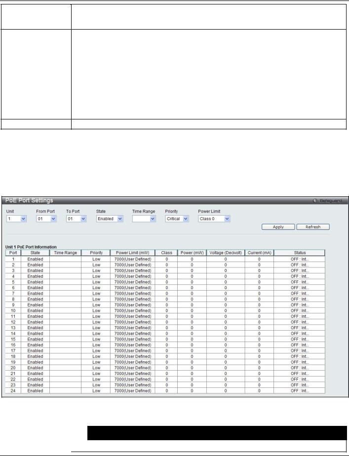
xStack® DES-3528/DES-3552 Series Layer 2 Stackable Fast Ethernet Managed Switch Web UI Reference Guide
Power Limit (1-370)
Power Disconnect
Method
Legacy PD
Sets the limit of power to be used from the Switch’s power source to PoE ports. The user may configure a Power Limit between 37W and 370W for the DES-3528P/DES-3552P. The default setting is 370W.
The PoE controller uses either Deny Next Port or Deny Low Priority Port to offset the power limit being exceeded and keeps the Switch’s power at a usable level. Use the drop-down menu to select a Power Disconnect Method. The default Power Disconnect Method is Deny Next Port. Both Power Disconnection Methods are described below:
Deny Next Port - After the power limit has been exceeded, the next port attempting to power up is denied, regardless of its priority. If Power Disconnection Method is set to Deny Next Port, the system cannot utilize out of its maximum power capacity. The maximum unused watt is 19W.
Deny Low Priority Port - After the power limit has been exceeded, the next port attempting to power up causes the port with the lowest priority to shut down so as to allow the highpriority and critical priority ports to power up.
Use the drop-down menu to enable or disable detecting legacy PDs signal.
Click the Apply button to implement changes made.
Click the Refresh button to update the display section of this page.
PoE Port Settings
To view the following window, click System Configuration > PoE > PoE Port Settings, as shown below:
Figure 2-8 PoE Port Settings window
The following parameters can be configured:
Parameter |
|
Description |
|
|
|
Unit |
Select the unit to configure. |
|
14

xStack® DES-3528/DES-3552 Series Layer 2 Stackable Fast Ethernet Managed Switch Web UI Reference Guide
From Port / To Port
State
Time Range
Priority
Power Limit
Select a range of ports from the pull-down menus to be enabled or disabled for PoE. Use the pull-down menu to enable or disable ports for PoE.
Select a range of the time to the port set as PoE. If Time Range is configured, the power can only be supplied during the specified period of time.
Use the pull-down menu to select the priority of the PoE ports. Port priority determines the priority which the system attempts to supply the power to the ports. There are three levels of priority that can be selected, critical, high, and low. When multiple ports happen to have the same level of priority, the port ID will be used to determine the priority. The lower port ID has higher priority. The setting of priority will affect the order of supplying power. Whether the disconnect method is set to deny low priority port, the priority of each port will be used by the system to manage the supply of power to ports.
This function is used to configure the per-port power limit. If a port exceeds its power limit, it will shut down.
Based on 802.3af/802.3at, there are different PD classes and power consumption ranges; Class 0 – 0.44~12.95W
Class 1 – 0.44~3.84W
Class 2 – 3.84~6.49W
Class 3 – 6.49~12.95W
Class 4 – 12.95W~29.5W (only ports 1~8)
The following is the power limit applied to the port for these five classes. For each class, the power limit is a little more than the power consumption range for that class. This takes into account any power loss on the cable. Thus, the following are the typical values;
Class 0 : 15400mW
Class 1 : 4000mW
Class 2 : 7000mW
Class 3 : 15400mW
User define: 30000mW (15400~30000 only applies to ports 1 - 8)
As well as these four pre-defined settings, users can directly specify any value ranging from 1000mW to 30000mW on DES-3528P/DES-3552P ports 1 to 8 and 1000mW - 15400mW on DES-3528P ports 9 to 24/DES-3552P ports 9 to 48.
NOTE: DES-3528P/DES-3552P ports 1 to 8 can support PoE up to 30W by configuring the PoE port user define value, also all ports can support 802.3af (1000 - 15400mW).
Click Apply to implement changes made. The port status of all PoE configured ports is displayed in the table in the bottom half of the screen shown above.
Click the Refresh button to update the display section of this page.
Serial Port Settings
This window allows the user to adjust the Baud Rate and the Auto Logout values.
To view the following window, click System Configuration > Serial Port Settings, as shown below:
Figure 2-9 Serial Port Settings window
15
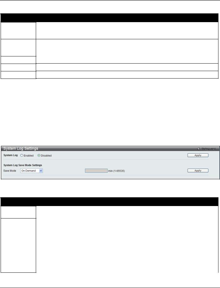
xStack® DES-3528/DES-3552 Series Layer 2 Stackable Fast Ethernet Managed Switch Web UI Reference Guide
The fields that can be configured are described below:
Parameter
Baud Rate
Auto Logout
Data Bits
Parity Bits
Stop Bits
Description
Specify the baud rate for the serial port on the Switch. There are four possible baud rates to choose from, 9600, 19200, 38400 and 115200. For a connection to the Switch using the console port, the baud rate must be set to 115200, which is the default setting.
Select the logout time used for the console interface. This automatically logs the user out after an idle period of time, as defined. Choose from the following options: 2, 5, 10, 15 minutes or Never. The default setting is 10 minutes.
Display the data bits used for the serial port connection. Display the parity bits used for the serial port connection. Display the stop bits used for the serial port connection.
Click the Apply button to implement changes made.
System Log configuration
System Log Settings
The Switch allows users to choose a method for which to save the switch log to the flash memory of the Switch.
To view the following window, click System Configuration > System Log Configuration > System Log Settings, as shown below:
Figure 2-10 System Log Settings window
The fields that can be configured are described below:
Parameter
System Log
Save Mode
Description
Use the radio buttons to enable or disable the system log settings. Click the Apply button to accept the changes made.
Use the pull-down menu to choose the method for saving the switch log to the flash memory. The user has three options:
On Demand – Users who choose this method will only save log files when they manually tell the Switch to do so, either using the Save Log link in the Save folder or clicking the Save Log Now button on this window.
Time Interval – Users who choose this method can configure a time interval by which the Switch will save the log files, in the box adjacent to this configuration field. The user may set a time between 1 and 65535 minutes.
Log Trigger – Users who choose this method will have log files saved to the Switch every time a log event occurs on the Switch.
Click the Apply button to accept the changes made for each individual section.
16

xStack® DES-3528/DES-3552 Series Layer 2 Stackable Fast Ethernet Managed Switch Web UI Reference Guide
System Log Server Settings
The Switch can send System log messages to up to four designated servers using the System Log Server.
To view the following window, click System Configuration > System Log Configuration > System Log Server Settings, as shown below:
Figure 2-11 System Log Server Settings
The fields that can be configured are described below:
Parameter Description
Server ID |
Syslog server settings index (1 to 4). |
Severity |
Use the drop-down menu to select the higher level of messages that will be sent. All |
|
messages which level is higher than selecting level will be sent. The options are |
|
Emergency, Alert, Critical, Error, Warning, Notice, Informational and Debug. |
Server IPv4 Address Click the radio button and enter the IPv4 address of the Syslog server. |
|
|
|
Server IPv6 Address Click the radio button and enter the IPv6 address of the Syslog server. |
|
Facility |
Use the drop-down menu to select Local 0, Local 1, Local 2, Local 3, Local 4, Local 5, |
|
Local 6, or Local 7. |
UDP Port |
Type the UDP port number used for sending Syslog messages. The default is 514. |
Status |
Choose Enabled or Disabled to activate or deactivate. |
Click the Apply button to accept the changes made.
Click the Delete All button to remove all servers configured.
System Log
Users can view and delete the local history log as compiled by the Switch's management agent.
To view the following window, click System Configuration > System Log Configuration > System Log, as shown below:
17

xStack® DES-3528/DES-3552 Series Layer 2 Stackable Fast Ethernet Managed Switch Web UI Reference Guide
Figure 2-12 System Log window
The Switch can record event information in its own log. Click Go to go to the next page of the System Log window.
The fields that can be configured or viewed are described below:
Parameter
Log Type
Index
Time
Level
Log Text
Description
In the drop-down menu the user can select the log type that will be displayed.
Severity - When selecting Severity from the drop-down menu, a secondary tick must be made. Secondary ticks are Emergency, Alert, Critical, Error, Warning, Notice, Informational and Debug. To view all information in the log, simply tick the All check box.
Module List - When selecting Module List, the module name must be manually entered like MSTP or ERPS.
Attack Log - When selecting Attack Log all attacks will be listed.
A counter incremented whenever an entry to the Switch's history log is made. The table displays the last entry (highest sequence number) first.
Display the time in days, hours, minutes, and seconds since the Switch was last restarted. Display the level of the log entry.
Display text describing the event that triggered the history log entry.
Click the Find button to display the log in the display section according to the selection made. Click the Clear Log button to clear the entries from the log in the display section.
Click the Clear Attack Log button to clear the entries from the attack log in the display section.
System Log & Trap Settings
The Switch allows users to configure the system log source IP interface addresses here.
To view the following window, click System Configuration > System Log Configuration > System Log & Trap Settings, as shown below:
18

xStack® DES-3528/DES-3552 Series Layer 2 Stackable Fast Ethernet Managed Switch Web UI Reference Guide
Figure 2-13 System Log & Trap Settings window (EI Mode Only)
The fields that can be configured are described below:
|
|
|
Parameter |
|
Description |
|
|
Enter the IP interface name used. |
Interface Name |
|
|
IPv4 Address |
|
Enter the IPv4 address used. |
IPv6 Address |
|
Enter the IPv6 address used. |
Click the Apply button to accept the changes made for each individual section.
Click the Clear button to clear all the information entered in the fields.
System Severity Settings
The Switch can be configured to allow alerts be logged or sent as a trap to an SNMP agent or both. The level at which the alert triggers either a log entry or a trap message can be set as well. Use the System Severity Settings window to set the criteria for alerts. The current settings are displayed below the System Severity Table.
To view the following window, click System Configuration > System Log Configuration > System Severity Settings, as shown below:
Figure 2-14 System Severity Settings window
The fields that can be configured are described below:
Parameter
System Severity
Severity Level
Description
Choose how the alerts are used from the drop-down menu. Select Log to send the alert of the Severity Type configured to the Switch’s log for analysis. Choose Trap to send it to an SNMP agent for analysis, or select All to send the chosen alert type to an SNMP agent and the Switch’s log for analysis.
This drop-down menu allows you to select the level of messages that will be sent. The options
19
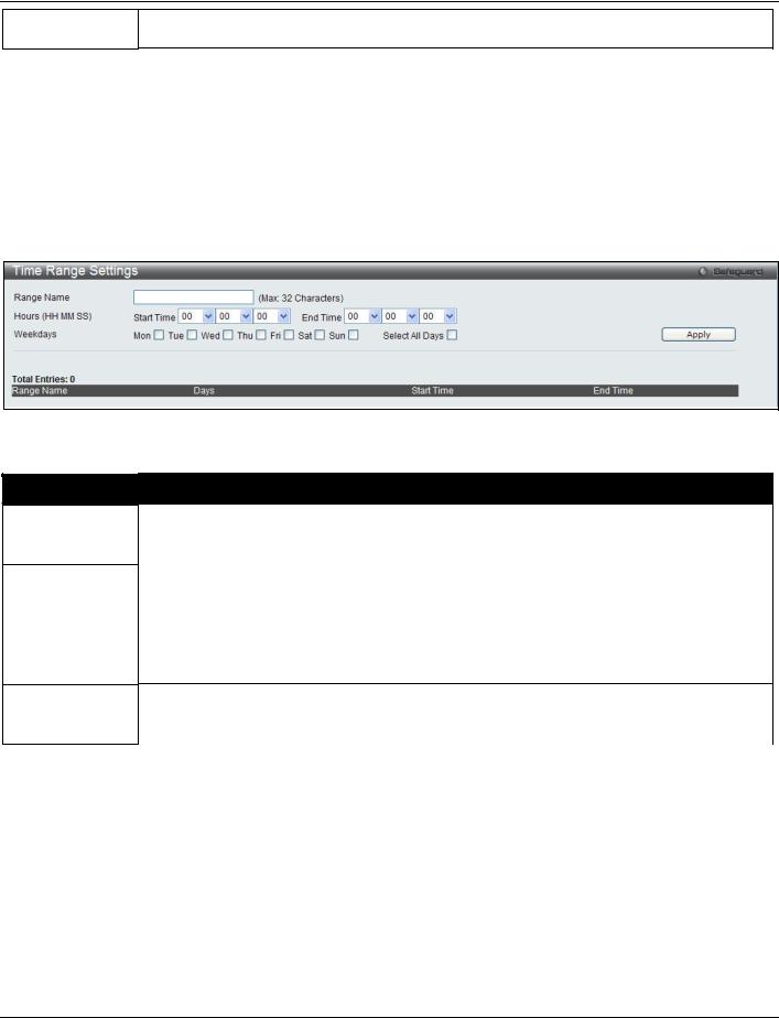
xStack® DES-3528/DES-3552 Series Layer 2 Stackable Fast Ethernet Managed Switch Web UI Reference Guide
are Emergency (0), Alert (1), Critical (2), Error (3), Warning (4), Notice (5), Information(6) and Debug(7).
Click the Apply button to accept the changes made.
Time Range Settings
Time range is a time period that the respective function will take an effect on, such as ACL. For example, the administrator can configure the time based ACL to allow users to surf the Internet on every Saturday and every Sunday, meanwhile to deny users to surf the Internet on weekdays.
The user may enter up to 64 time range entries on the Switch.
To view the following window, click System Configuration > Time Range Settings, as shown below:
Figure 2-15 Time Range Settings window
The fields that can be configured are described below:
Parameter
Range Name
Hours
Weekdays
Description
Enter a name of no more than 32 alphanumeric characters that will be used to identify this time range on the Switch. This range name will be used in the Access Profile table to identify the access profile and associated rule to be enabled during this time range.
This parameter is used to set the time in the day that this time range is to be enabled using the following parameters:
Start Time - Use this parameter to identify the starting time of the time range, in hours, minutes and seconds, based on the 24-hour time system.
End Time - Use this parameter to identify the ending time of the time range, in hours, minutes and seconds, based on the 24-hour time system.
Use the check boxes to select the corresponding days of the week that this time range is to be enabled. Tick the Select All Days check box to configure this time range for every day of the week.
Click the Apply button to accept the changes made. Current configured entries will be displayed in the table in the bottom half of the window shown above.
Time Settings
Users can configure the time settings for the Switch.
To view the following window, click System Configuration > Time Settings, as shown below:
20

xStack® DES-3528/DES-3552 Series Layer 2 Stackable Fast Ethernet Managed Switch Web UI Reference Guide
|
Figure 2-16 Time Settings window |
The fields that can be configured are described below: |
|
Parameter |
Description |
|
Enter the current day, month, and year to update the system clock. |
Date (DD/MM/YYYY) |
|
Time (HH:MM:SS) |
Enter the current time in hours, minutes, and seconds. |
Click the Apply button to accept the changes made.
User Accounts Settings
The Switch allows the control of user privileges.
To view the following window, click System Configuration > User Accounts Settings, as shown below:
Figure 2-17 User Accounts Settings window
To add a new user, type in a User Name and New Password and retype the same password in the Confirm New Password field. Choose the level of privilege (Admin, Operator, Power_User or User) from the Access Right drop-down menu.
|
Management |
Admin |
|
Operator |
Power_User |
User |
|
|
|
||||||
|
Configuration |
Read/Write |
|
Read/Write– |
Read/Write– |
No |
|
|
|
|
|
partly |
partly |
|
|
|
Network Monitoring |
Read/Write |
|
Read/Write |
Read-only |
Read-only |
|
|
Community Strings and Trap |
Read/Write |
|
Read-only |
Read-only |
Read-only |
|
|
Stations |
|
|
|
|
|
|
|
Update Firmware and Configuration |
Read/Write |
|
No |
No |
No |
|
|
Files |
|
|
|
|
|
|
|
System Utilities |
Read/Write |
|
Read-only |
Read-only |
Read-only |
|
|
Factory Reset |
Read/Write |
|
No |
No |
No |
|
|
User Account Management |
|
|
|
|
|
|
|
Add/Update/Delete User Accounts |
Read/Write |
|
No |
No |
No |
|
|
View User Accounts |
Read/Write |
|
No |
No |
No |
|
|
|
|
|
|
|
|
|
|
|
|
21 |
|
|
|
|
Loading...