


 Loading...
Dell EMC PowerEdge MX740c
Installation and Service Manual
Regulatory Model: E04B
Regulatory Type: E04B001
December 2020
Rev. A10

Notes, cautions, and warnings

 NOTE: A NOTE indicates important information that helps you make better use of your product.
 CAUTION: A CAUTION indicates either potential damage to hardware or loss of data and tells you how to avoid the problem.
 WARNING: A WARNING indicates a potential for property damage, personal injury, or death.
© 2019 - 2020 Dell Inc. or its subsidiaries. All rights reserved. Dell, EMC, and other trademarks are trademarks of Dell Inc. or its subsidiaries. Other trademarks may be trademarks of their respective owners.

Contents
Chapter 1: About this document.................................................................................................... |
6 |
Chapter 2: PowerEdge MX740c sled overview............................................................................... |
7 |
Front view of the system................................................................................................................................................... |
8 |
Inside the system................................................................................................................................................................. |
8 |
Locating the Service Tag of your system...................................................................................................................... |
9 |
System information label.................................................................................................................................................. |
10 |
Chapter 3: Initial system setup and configuration........................................................................ |
13 |
Setting up your system..................................................................................................................................................... |
13 |
iDRAC configuration.......................................................................................................................................................... |
13 |
Options to set up iDRAC IP address........................................................................................................................ |
13 |
Log in to iDRAC............................................................................................................................................................ |
14 |
Options to install the operating system........................................................................................................................ |
14 |
Methods to download firmware and drivers.......................................................................................................... |
15 |
Downloading drivers and firmware........................................................................................................................... |
15 |
Chapter 4: Installing and removing system components............................................................... |
16 |
Safety instructions............................................................................................................................................................. |
16 |
Before working inside your sled...................................................................................................................................... |
17 |
After working inside your sled......................................................................................................................................... |
17 |
Recommended tools.......................................................................................................................................................... |
17 |
PowerEdge MX740c sled................................................................................................................................................. |
17 |
Removing the sled from enclosure........................................................................................................................... |
17 |
Installing the sled into enclosure.............................................................................................................................. |
19 |
System cover..................................................................................................................................................................... |
20 |
Removing the system cover..................................................................................................................................... |
20 |
Installing system cover................................................................................................................................................ |
21 |
Air shroud............................................................................................................................................................................ |
23 |
Removing air shroud................................................................................................................................................... |
23 |
Installing air shroud..................................................................................................................................................... |
23 |
Drives................................................................................................................................................................................... |
24 |
Removing drive blank.................................................................................................................................................. |
24 |
Installing drive blank.................................................................................................................................................... |
25 |
Removing drive carrier............................................................................................................................................... |
25 |
Installing drive carrier................................................................................................................................................. |
26 |
Removing a drive from drive carrier........................................................................................................................ |
27 |
Installing a drive into drive carrier........................................................................................................................... |
28 |
Drive backplane.................................................................................................................................................................. |
29 |
Removing drive backplane......................................................................................................................................... |
30 |
Installing drive backplane............................................................................................................................................ |
31 |
Cable routing...................................................................................................................................................................... |
32 |
Drive cage........................................................................................................................................................................... |
36 |
Removing the drive cage........................................................................................................................................... |
36 |
Contents 3
Installing the drive cage............................................................................................................................................. |
37 |
Battery backup unit ......................................................................................................................................................... |
38 |
Removing the battery backup unit.......................................................................................................................... |
38 |
Installing the battery backup unit............................................................................................................................ |
39 |
Removing the BBU from the BBU cage................................................................................................................. |
40 |
Installing the BBU into the BBU cage..................................................................................................................... |
41 |
Control panel...................................................................................................................................................................... |
42 |
Removing the control panel...................................................................................................................................... |
42 |
Installing the control panel ....................................................................................................................................... |
43 |
System memory................................................................................................................................................................. |
44 |
General memory module installation guidelines.................................................................................................... |
46 |
NVDIMM-N memory module installation guidelines ........................................................................................... |
46 |
DCPMM installation guidelines ................................................................................................................................ |
48 |
Mode-specific guidelines........................................................................................................................................... |
50 |
Removing a memory module..................................................................................................................................... |
53 |
Installing a memory module....................................................................................................................................... |
54 |
Processors and heat sinks.............................................................................................................................................. |
55 |
Removing the processor and heat sink module................................................................................................... |
55 |
Removing the processor from the processor and heat sink module.............................................................. |
56 |
Installing the processor into a processor and heat sink module....................................................................... |
57 |
Installing a processor and heat sink module......................................................................................................... |
60 |
iDRAC card.......................................................................................................................................................................... |
61 |
Removing the iDRAC card......................................................................................................................................... |
61 |
Installing the iDRAC card........................................................................................................................................... |
62 |
PERC card........................................................................................................................................................................... |
63 |
Removing the PERC card.......................................................................................................................................... |
64 |
Installing the PERC card............................................................................................................................................ |
64 |
Removing the Jumbo PERC card............................................................................................................................ |
65 |
Installing the Jumbo PERC card.............................................................................................................................. |
66 |
Optional Internal dual SD module.................................................................................................................................. |
67 |
Removing the IDSDM card........................................................................................................................................ |
67 |
Installing the IDSDM card.......................................................................................................................................... |
68 |
Removing a MicroSD card......................................................................................................................................... |
69 |
Installing a MicroSD card........................................................................................................................................... |
70 |
M.2 BOSS module.............................................................................................................................................................. |
71 |
Removing the M.2 BOSS module............................................................................................................................. |
71 |
Installing the M.2 BOSS module............................................................................................................................... |
72 |
Removing the M.2 BOSS card.................................................................................................................................. |
73 |
Installing the M.2 BOSS card.................................................................................................................................... |
74 |
Mezzanine card.................................................................................................................................................................. |
75 |
Removing the Mezzanine card................................................................................................................................. |
75 |
Installing the Mezzanine card................................................................................................................................... |
76 |
Removing the mini Mezzanine card........................................................................................................................ |
77 |
Installing the mini Mezzanine card.......................................................................................................................... |
78 |
Removing the mini Mezzanine card blank............................................................................................................. |
79 |
Installing the mini Mezzanine card blank............................................................................................................... |
80 |
Optional internal USB memory key................................................................................................................................ |
81 |
Replacing the optional internal USB memory key................................................................................................ |
81 |
System battery................................................................................................................................................................... |
81 |
Replacing the system battery - Option A............................................................................................................... |
81 |
4 Contents
Replacing the system battery - Option B.............................................................................................................. |
83 |
System board..................................................................................................................................................................... |
84 |
Removing the system board..................................................................................................................................... |
84 |
Installing the system board....................................................................................................................................... |
86 |
Trusted Platform Module................................................................................................................................................ |
88 |
Upgrading the TPM.................................................................................................................................................... |
89 |
Initializing TPM for BitLocker users........................................................................................................................ |
90 |
Initializing the TPM 1.2 for TXT users.................................................................................................................... |
90 |
Initializing the TPM 2.0 for TXT users................................................................................................................... |
90 |
Chapter 5: Jumpers and connectors............................................................................................ |
92 |
System board jumpers and connectors....................................................................................................................... |
92 |
System board jumper settings....................................................................................................................................... |
93 |
Disabling a forgotten password..................................................................................................................................... |
94 |
Chapter 6: System diagnostics and indicator codes .................................................................... |
95 |
Power button LED............................................................................................................................................................ |
95 |
Drive indicator codes........................................................................................................................................................ |
95 |
System health and system ID indicator codes........................................................................................................... |
96 |
System diagnostics........................................................................................................................................................... |
96 |
Dell Embedded System Diagnostics........................................................................................................................ |
97 |
Chapter 7: Getting help............................................................................................................... |
98 |
Contacting Dell EMC........................................................................................................................................................ |
98 |
Documentation feedback................................................................................................................................................ |
98 |
Accessing system information by using QRL............................................................................................................. |
98 |
Quick Resource Locator for PowerEdge MX740c system................................................................................ |
99 |
Receiving automated support with SupportAssist .................................................................................................. |
99 |
Recycling or End-of-Life service information............................................................................................................ |
99 |
Chapter 8: Documentation resources......................................................................................... |
100 |
Contents 5

1
About this document
This document provides an overview about the PowerEdge MX740c system, information about installing and replacing components, technical specifications, diagnostic tools, and guidelines to be followed while installing certain components.
The PowerEdge MX740c is compatible with the PowerEdge MX7000 enclosure. For more information about the enclosure, refer to the Installation and Service Manual for the PowerEdge MX7000 at www.dell.com/poweredgemanuals.
6 About this document

2
PowerEdge MX740c sled overview
The Dell EMCPowerEdge MX740c is a single width compute sled and supports:
●Up to two Intel Xeon Scalable processors.
●Up to 24 DIMM slots.
●Up to six 2.5-inch SAS, SATA (HDD/SSD), or NVMe drives.
NOTE: All instances of SAS, NVMe, SATA HDDs, and SSDs are referred to as drives in this document, unless specified otherwise.
Topics:
•Front view of the system
•Inside the system
•Locating the Service Tag of your system
•System information label
PowerEdge MX740c sled overview |
7 |

Front view of the system
Figure 1. Front view of the 6 drive configuration
1.USB 3.0 port
2.iDRAC direct port
3.Drives
4.Release handle
5.Release handle button
6.Information tag
7.System health and System ID indicator
8.Power button
For more information about the ports, see Technical Specifications.
Inside the system
 NOTE: Components that are hot swappable have orange touch points and the components that are not hot swappable have blue touch points.
8 PowerEdge MX740c sled overview
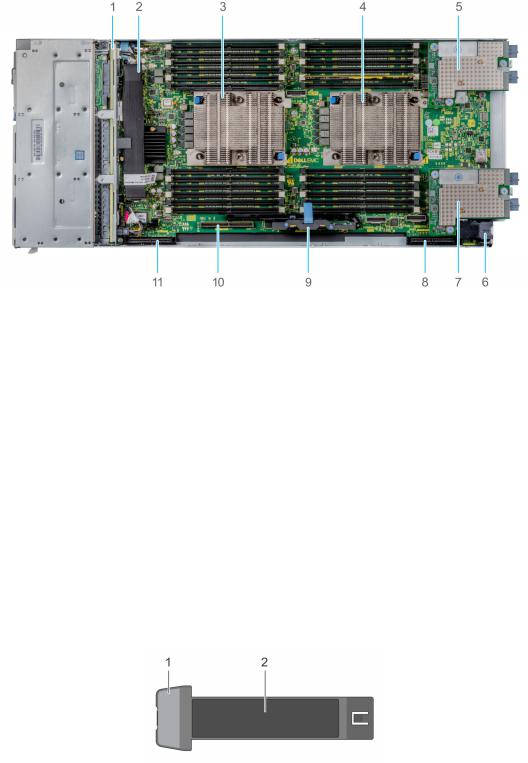
Figure 2. Inside the system
1.Backplane
2.Backplane cable
3.Processor 1 (heat sink)
4.Processor 2 (heat sink)
5.Mezzanine card A1
6.Power connector
7.Mezzanine card B1
8.Mini Mezzanine connector
9.iDRAC card
10.BOSS connector
11.PERC connector
Locating the Service Tag of your system
The System Information Tab contains the system's unique Express Service Code and Service Tag. This information is used by Dell EMC to identify system configuration, warranty terms, and to route support calls to the appropriate personnel. A Quick Resource Locator (QRL) label on the System Information Tab links to a web page that shows the exact factory configuration and specific warranty purchased.
Figure 3. Locating Service Tag of your system
1.Information tag
2.Service tag
PowerEdge MX740c sled overview |
9 |
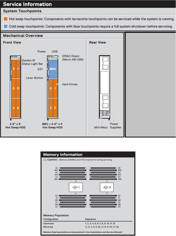
System information label
Figure 4. Mechanical overview
Figure 5. Memory information
10 PowerEdge MX740c sled overview

Figure 6. System board
Figure 7. Removal of IDSDM and Internal USB memory key(optional)
Figure 8. Removal of BBU module and drive cage
PowerEdge MX740c sled overview |
11 |
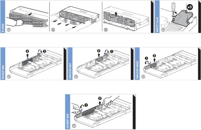
Figure 9. Removal of backplane and Mezzanine card
Figure 10. Removal of PERC cards and Mini Mezzanine card
Figure 11. Removal of Jumbo PERC card
12 PowerEdge MX740c sled overview

3
Initial system setup and configuration
Topics:
•Setting up your system
•iDRAC configuration
•Options to install the operating system
Setting up your system
Complete the following steps to set up your system:
Steps
1.Unpack the system.
2.Remove the I/O connector cover from the system connectors.
 CAUTION: While installing the system, ensure that it is properly aligned with the slot on the enclosure to prevent damage to the system connectors.
3.Install the system in the enclosure.
4.Turn on the enclosure.

 NOTE: Wait for the enclosure to initialize before you press the power button.
5.Press the power button on the system.
Alternatively, you can also turn on the system by using iDRAC:
●For more information, see the Log in to iDRAC on page 14
●Open OpenManage Enterprise modular(OME modular), after the iDRAC is configured on the OME. For more information, see the OME-modular User’s Guide at Dell.com/manuals.
iDRAC configuration
The Integrated Dell Remote Access Controller (iDRAC) is designed to make system administrators more productive and improve the overall availability of Dell systems. iDRAC alerts administrators about system issues and enables them to perform remote system management. This reduces the need for physical access to the system.
Options to set up iDRAC IP address
You must configure the initial network settings based on your network infrastructure to enable the communication to and from iDRAC.
You can set up the IP address by using one of the following interfaces:
Interfaces |
Document/Section |
iDRAC Settings |
See Dell Integrated Dell Remote Access Controller User's Guide at www.dell.com/poweredgemanuals |
utility |
|
Dell Deployment |
See Dell Deployment Toolkit User’s Guide at www.dell.com/openmanagemanuals > OpenManage |
Toolkit |
Deployment Toolkit |
Initial system setup and configuration |
13 |

Interfaces Document/Section
Dell Lifecycle See Dell Lifecycle Controller User’s Guide at www.dell.com/poweredgemanuals
Controller
OME Modular See Dell OpenManagement Enterprise Modular User’s Guide at www.dell.com/openmanagemanuals
iDRAC Direct See Dell Integrated Dell Remote Access Controller User's Guide at www.dell.com/poweredgemanuals
Log in to iDRAC
You can log in to iDRAC as:
●iDRAC user
●Microsoft Active Directory user
●Lightweight Directory Access Protocol (LDAP) user
If you have opted for secure default access to iDRAC, you must use the iDRAC secure default password available on the system Information tag. If you have not opted for secure default access to iDRAC, then use the default user name and password –root and calvin. You can also log in by using your Single Sign-On or Smart Card.

 NOTE: You must have the iDRAC credentials to log in to iDRAC.

 NOTE: Ensure that you change the default username and password after setting up the iDRAC IP address.
 NOTE: The Intel Quick Assist Technology (QAT) on the Dell EMC PowerEdge MX740c is supported with chipset integration and is enabled through an optional license. The license files are enabled on the sleds through iDRAC.
For more information about drivers, documentation, and white papers on the Intel QAT, see https://01.org/intel-quickassist- technology.
For more information about logging in to the iDRAC and iDRAC licenses, see the latest Integrated Dell Remote Access Controller User's Guide at www.dell.com/poweredgemanuals.
You can also access iDRAC by using RACADM. For more information, see the RACADM Command Line Interface Reference Guide at www.dell.com/poweredgemanuals.
Options to install the operating system
If the system is shipped without an operating system, install the supported operating system by using one of the following resources:
Table 1. Resources to install the operating system
Resources |
Location |
|
|
|
|
iDRAC |
www.dell.com/idracmanuals |
|
|
Lifecycle Controller |
www.dell.com/idracmanuals |
|
|
OpenManage Deployment Toolkit |
www.dell.com/openmanagemanuals > OpenManage |
|
Deployment Toolkit |
|
|
Dell certified VMware ESXi |
www.dell.com/virtualizationsolutions |
|
|
Installation and How-to videos for supported operating |
Supported Operating Systems for Dell PowerEdge Systems |
systems on PowerEdge systems |
|
|
|
 NOTE: Virtual Media is optional for integrated Dell Remote Access Controllers (iDRAC) with an Enterprise license (iDRAC 7, 8 and 9) or module (iDRAC 6).It allows the usage of software image files (ISO-files), which can be used for installing operating systems or updating servers.
14 Initial system setup and configuration

Methods to download firmware and drivers
You can download the firmware and drivers by using any of the following methods:
Table 2. Firmware and drivers
Methods |
Location |
|
|
|
|
From the Dell EMC support site |
www.dell.com/support/home |
|
|
Using Dell Remote Access Controller Lifecycle Controller |
www.dell.com/idracmanuals |
(iDRAC with LC) |
|
|
|
Using Dell Repository Manager (DRM) |
www.dell.com/openmanagemanuals > Repository Manager |
|
|
Using Dell OpenManage Essentials |
www.dell.com/openmanagemanuals > OpenManage Essentials |
|
|
Using Dell OpenManage Enterprise |
www.dell.com/openmanagemanuals > OpenManage |
|
Enterprise |
|
|
Using Dell Server Update Utility (SUU) |
www.dell.com/openmanagemanuals > Server Update Utility |
|
|
Using Dell OpenManage Deployment Toolkit (DTK) |
www.dell.com/openmanagemanuals > OpenManage |
|
Deployment Toolkit |
|
|
Using iDRAC virtual media |
www.dell.com/idracmanuals |
|
|
Downloading drivers and firmware
Dell EMC recommends that you download and install the latest BIOS, drivers, and systems management firmware on your system.
Prerequisites
Ensure that you clear the web browser cache before downloading the drivers and firmware.
Steps
1.Go to www.dell.com/support/home.
2.In the Drivers & Downloads section, type the Service Tag of your system in the Enter a Service Tag or product ID box, and then click Submit.
 NOTE: If you do not have the Service Tag, select Detect Product to allow the system to automatically detect the Service Tag, or click View products, and navigate to your product.
3.Click Drivers & Downloads.
The drivers that are applicable to your system are displayed.
4.Download the drivers to a USB drive, CD, or DVD.
Initial system setup and configuration |
15 |

4
Installing and removing system components
Topics:
•Safety instructions
•Before working inside your sled
•After working inside your sled
•Recommended tools
•PowerEdge MX740c sled
•System cover
•Air shroud
•Drives
•Drive backplane
•Cable routing
•Drive cage
•Battery backup unit
•Control panel
•System memory
•Processors and heat sinks
•iDRAC card
•PERC card
•Optional Internal dual SD module
•M.2 BOSS module
•Mezzanine card
•Optional internal USB memory key
•System battery
•System board
•Trusted Platform Module
Safety instructions
NOTE: Whenever you need to lift the system, get others to assist you. To avoid injury, do not attempt to lift the system by yourself.
 WARNING: Opening or removing the system cover while the system is powered on may expose you to a risk of electric shock.
 CAUTION: Do not operate the system without the cover for a duration exceeding five minutes. Operating the system without the system cover can result in component damage.
 CAUTION: Many repairs may only be done by a certified service technician. You should only perform troubleshooting and simple repairs as authorized in your product documentation, or as directed by the online or telephone service and support team. Damage due to servicing that is not authorized by Dell is not covered by your warranty. Read and follow the safety instructions that are shipped with your product.
NOTE: It is recommended that you always use an antistatic mat and antistatic strap while working on components inside the system.
 CAUTION: To ensure proper operation and cooling, all bays in the system and system fans must be always populated with a component or a blank.
16 Installing and removing system components

Before working inside your sled
Prerequisites
Follow the safety guidelines listed in Safety instructions on page 16.
Steps
1.Power off the sled.
2.Remove the sled from the enclosure.
3.If applicable install the I/O connector cover.
 CAUTION: To prevent damage to the I/O connectors on the system, ensure that you cover the connectors when you remove the system from the enclosure.
4.Remove the system cover.
After working inside your sled
Prerequisites
Follow the safety guidelines listed in Safety instructions on page 16.
Steps
1.Install the system cover.
2.If installed, remove the I/O connector cover on the system.

 CAUTION: To prevent damage to the I/O connectors, do not touch the connectors or the connector pins.
3.Install the sled in the enclosure.
4.Power on the sled.

 NOTE: Ability to power on the sled requires iDRAC to fully initialize first.
Recommended tools
You need the following tools to perform the removal and installation procedures:
●Phillips #1 and Phillips #2 screwdrivers
●Torx T15 and T30 screwdrivers
●Wrist grounding strap
PowerEdge MX740c sled
The PowerEdge MX740c sled is a server unit that is installed into the PowerEdge MX7000 enclosure.
Removing the sled from enclosure
Prerequisites
1.Follow the safety guidelines listed in Safety Instructions.
2.Power off the sled.
Installing and removing system components |
17 |
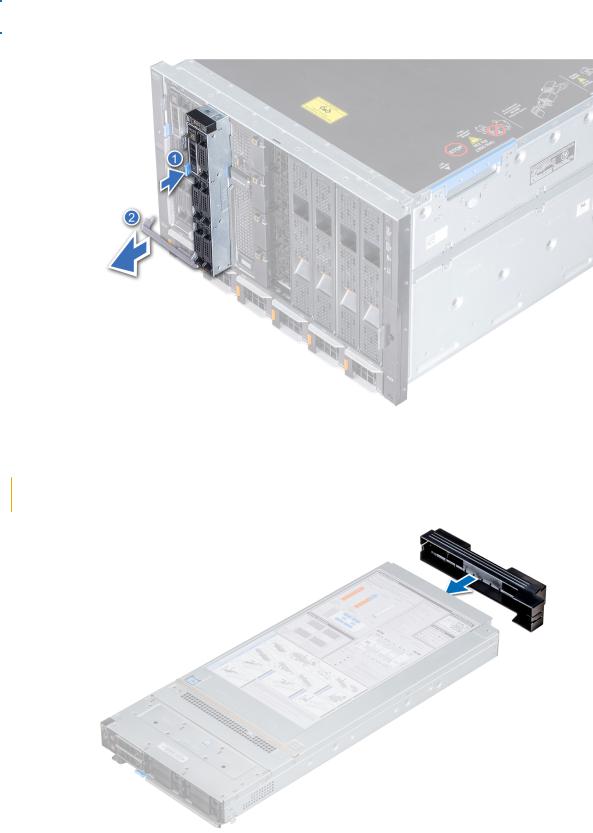
Steps
1.Press the blue release button on the sled to release the sled handle.
2.Holding the sled handle, slide the sled out of the enclosure.

 NOTE: Support the system with both hands while sliding it out of the enclosure.

 NOTE: Removing the sled with the enclosure powered on is supported if you shut down the sled before removal.
Figure 12. Removing the sled from enclosure
3.Install the I/O connector cover on the sled.
 CAUTION: To protect the I/O connector pins, install the I/O connector cover every time a sled is removed from the enclosure.
Figure 13. Installing the I/O connector cover on sled
18 Installing and removing system components
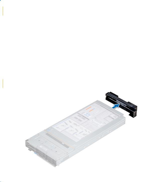

 NOTE: The color of the I/O connector cover may differ.
 CAUTION: If you are permanently removing the sled, install a sled blank promptly. Operating the enclosure without a blank, for an extended time can result in overheating or performance loss.
Next steps
1. Install the sled or the sled blank into the enclosure.
Installing the sled into enclosure
Prerequisites
1.Follow the safety guidelines listed in Safety instructions on page 16.

 CAUTION: To prevent damage to the I/O connectors, do not touch the connectors or the connector pins.
Steps
1.Remove the I/O connector cover from the I/O connector(s) and store for future use.
 CAUTION: To protect the I/O connector pins, install the I/O connector cover every time a sled is removed from the enclosure.
Figure 14. Removing the I/O connector cover from sled

 NOTE: The color of the I/O connector cover may differ.
2.Press the blue release button on the sled to release the sled handle.
3.Holding the sled with both hands, align the sled with the compute sled-bay in the enclosure.
4.Slide the sled into the enclosure, until the sled handle is in the lock position.
5.Push the sled handle inwards so that it locks into place to secure the sled in the enclosure.
Installing and removing system components |
19 |
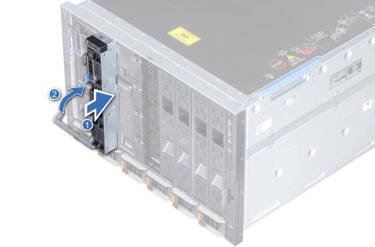
Figure 15. Installing the sled into enclosure
Next steps
1. Power on the sled.
System cover
The system cover protects the components inside the system and helps in maintaining air flow inside the system.
Removing the system cover
Prerequisites
1.Follow the safety guidelines listedin Safety instructions on page 16.
2.Power off the sled.
3.Remove the sled from the enclosure.
4.Place the sled on the flat surface with the top cover facing upwards.
Steps
1.Press the blue release tab on the system cover and slide the cover towards the rear of the system.
2.Hold the cover on both sides, and lift the cover away from the system.
20 Installing and removing system components
Figure 16. Removing system cover
Next steps
1. Replace the system cover.
Installing system cover
Prerequisites
1.Follow the safety guidelines listed in Safety instructions on page 16.
2.Ensure that all internal cables are routed correctly and connected, and no tools or extra parts are left inside the system.
Steps
1.Align the tabs on the system cover with the guide slots on the system.
2.Slide the cover towards the front of the system.
Installing and removing system components |
21 |
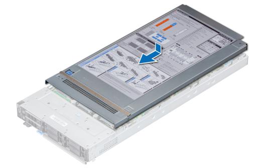
Figure 17. Installing system cover
Next steps
1.Install the sled into the enclosure.
2.Turn on the sled.
22 Installing and removing system components
Air shroud
The air shroud aerodynamically directs the airflow across the entire system. The airflow passes air through all the critical parts of the system thus allowing increased cooling preventing overheating.
Removing air shroud
Prerequisites
 CAUTION: Never operate your system with the air shroud removed. The system may get overheated quickly, resulting in shutdown of the system and loss of data.
1.Follow the safety guidelines listed in Safety Instructions.
2.Follow the procedure listed in Before working inside your sled on page 17.
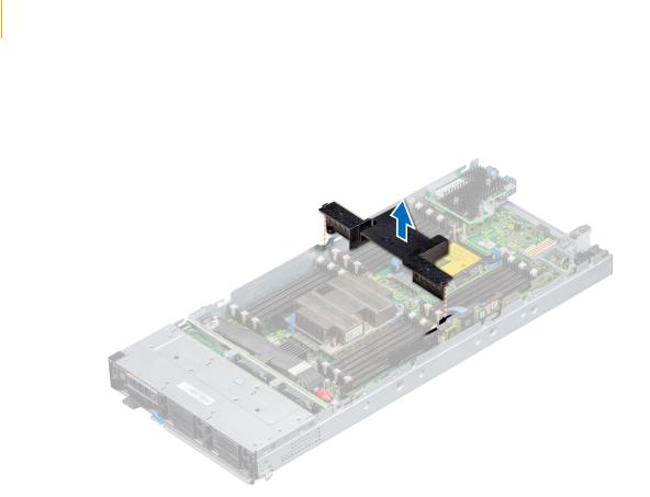
Steps
Hold both the edges of the air shroud and lift it out of the system.
Figure 18. Removing air shroud
Next steps
1. Install the air shroud.
Installing air shroud
Prerequisites
1.Follow the safety guidelines listed in Safety Instructions.
2.Follow the procedure listed in Before working inside your sled on page 17.
Steps
1.Align the air shroud with the guide slots on the system.
2.Lower the air shroud into the system until it is firmly seated.
Installing and removing system components |
23 |
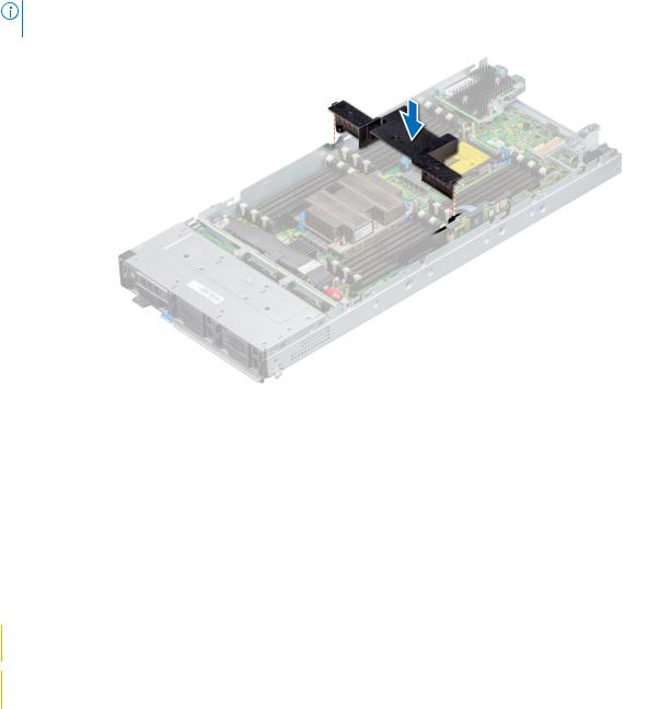
NOTE: When firmly seated, the memory socket and processor numbers marked on the air shroud aligns with the respective memory socket and processor numbers marked on the system.
Figure 19. Installing air shroud
Next steps
1. Follow the procedure listed in After working inside the sled.
Drives
Your system supports 2.5-inch SAS/SATA SSD, NVMe drives and PCIe SSDs. The drives or SSDs are supplied in a hotswappable drive carriers that fit in the drive bays and these drives connect to the system board through the drive backplane.
 CAUTION: Before attempting to remove or install a drive while the system is running, see the documentation to ensure that the host adapter is configured correctly to support hot-swap drive removal and insertion.
 CAUTION: Do not turn off or restart your system while the drive is being formatted. Doing so can cause a drive failure.
When you format a drive, allow enough time for the formatting to be complete. The high-capacity drives can take a long time to format.
Removing drive blank
Prerequisites
1. Follow the safety guidelines listed in Safety instructions on page 16

 CAUTION: Mixing drive blanks from previous generations of PowerEdge servers is not supported
 CAUTION: To maintain proper system cooling, all empty drive slots must have drive blanks installed.
Steps
Press the release button and slide the drive blank out of the drive slot.
24 Installing and removing system components
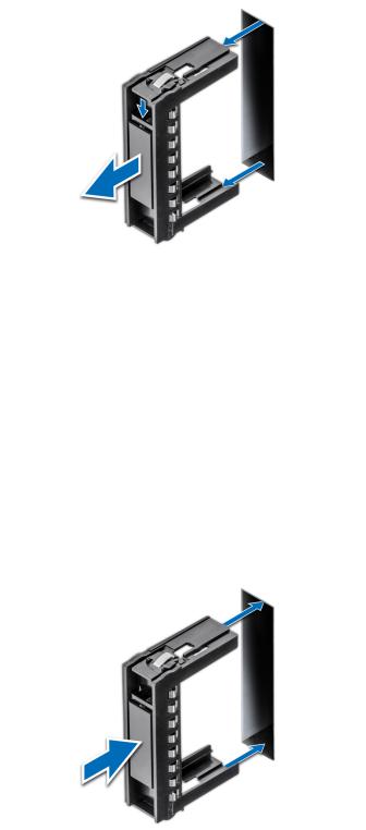
Figure 20. Removing drive blank
Next steps
1. Install a drive or a drive blank.
Installing drive blank
Prerequisites
1. Follow the safety guidelines listed in Safety instructions on page 16.

 CAUTION: Mixing drive blanks from previous generations of PowerEdge servers is not supported.
Steps
Insert the drive blank into the drive slot and push the blank until the release button clicks into place.
Figure 21. Installing drive blank
Removing drive carrier
Prerequisites
1.Follow the safety guidelines listed in Safety instructions on page 16.
2.Using the management software, prepare the drive for removal.
Installing and removing system components |
25 |
If the drive is online, the green activity or fault indicator flashes while the drive is turning off. When the drive indicators are off, the drive is ready for removal. For more information, see the documentation for the storage controller.
 CAUTION: Before attempting to remove or install a drive while the system is running, see the documentation for the storage controller card to ensure that the host adapter is configured correctly to support drive removal and insertion.
 CAUTION: Mixing drive carriers from previous generations or other platforms of PowerEdge servers is not supported.
 CAUTION: To prevent data loss, ensure that your operating system supports hot-swap drive installation. See the documentation supplied with your operating system.
 CAUTION: To maintain proper system cooling, all empty drive bays must have drive blanks installed.
 WARNING: Ensure that you back up your data, before removing a drive. For more information about preparing your drive for removal and supported RAID redundancy, see the Troubleshooting guide of your system at www.dell.com/poweredgemanuals.
Steps
1.Press the release button to open the release handle.
2.Holding the handle, slide the drive carrier out of the drive slot.
Figure 22. Removing drive carrier
Next steps
1. Replace the drive carrier or a drive blank.
Installing drive carrier
Prerequisites
 CAUTION: Before attempting to remove or install a drive while the system is running, see the documentation for the storage controller card to ensure that the host adapter is configured correctly to support drive removal and insertion.

 CAUTION: Mixing drive carriers from previous generations of PowerEdge servers is not supported.
26 Installing and removing system components

 CAUTION: Combining SAS and SATA drives in the same RAID volume is not supported.
 CAUTION: When installing a drive carrier, ensure that the adjacent drives are fully installed. Inserting a drive carrier and attempting to lock its handle next to a partially installed carrier can damage the partially installed carrier's shield spring and make it unusable.
 CAUTION: To prevent data loss, ensure that your operating system supports hot-swap drive installation. See the documentation supplied with your operating system.
 CAUTION: When a replacement hot swappable drive is installed and the system is powered on, the drive automatically begins to rebuild. Ensure that the replacement drive is blank or contains data that you wish to overwrite. Any data on the replacement drive is immediately lost after the drive is installed.
1.Follow the safety guidelines listed in the Safety instructions.
2.If installed, remove the drive blank.
Steps
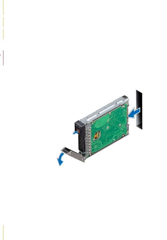
1.Press the release button on the front of the drive carrier to open the release handle.
2.Insert the drive carrier into the drive slot and slide until the drive carrier connects with the backplane.
3.Close the release handle of the drive carrier to lock the drive in place.
Figure 23. Installing drive carrier
Removing a drive from drive carrier
Prerequisites
1.Follow the safety guidelines listed in Safety instructions on page 16.
2.Remove the drive carrier.
Steps
1.Using the Phillips #1 screwdriver, remove the screws from the slide rails on the drive carrier.
2.Lift the drive out of the drive carrier.
Installing and removing system components |
27 |
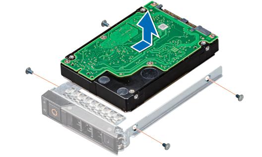
Figure 24. Removing a drive from drive carrier
Next steps
1. Replace the drive into the drive carrier.
Installing a drive into drive carrier
Prerequisites
1. Follow the safety guidelines listed in Safety instructions on page 16
Steps
1.Insert the drive into the drive carrier, with the connector end of the drive towards the back of the carrier.
2.Align the screw holes on the drive with the screw holes on the drive carrier.
3.Using the Phillips #1 screwdriver, replace the screws to secure the drive to the drive carrier.
28 Installing and removing system components
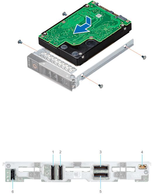
Figure 25. Installing a drive into drive carrier
Drive backplane
Depending on the configuration, your system supports:
●2.5 inch (x6) Universal backplane
●2.5 inch (x6) SAS/SATA backplane
●2.5 inch (x4) Universal backplane
Figure 26. 6 x 2.5-inch universal backplane
1.AUX 2 cable connector
2.AUX 1 cable connector
3.SAS/SATA connector
4.Signal cable connector
5.AUX 0 cable connector
6.Power cable connector
Installing and removing system components |
29 |
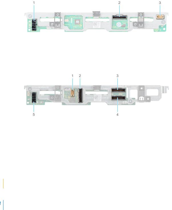
Figure 27. 6 x 2.5-inch SAS/SATA backplane
1.Power cable connector
2.SAS/SATA connector
3.Signal cable connector
Figure 28. 4 x 2.5-inch universal backplane
1.Signal cable connector
2.AUX 1 cable connector
3.SAS/SATA connector
4.AUX 0 cable connector
5.Power cable connector
Removing drive backplane
Prerequisites
 CAUTION: To prevent damage to the drives and the drive backplane, you must remove the drives from the system before removing the drive backplane. For more information, see Removing a drive carrier.

 CAUTION: Temporarily label drives before you remove the drive so that you can replace them in the same slots.
 NOTE: Observe the routing of the cable as you remove it from the sled. Route the cable properly when you replace it, to prevent the cable from being pinched or crimped.
1.Follow the safety guidelines listed in Safety Instructions.
2.Follow the procedure listed in Before working inside your sled.
3.Disconnect the cables connected to the backplane.
4.Remove the drives.
Steps
1.Hold the drive backplane by the edges and lift it upwards to disengage the backplane from the guide pins.
2.Lift the backplane out of the sled.
30 Installing and removing system components
Loading...