


PowerConnect J-SRX240
Use the instructions in this quick start to help you connect the Dell PowerConnect
J-Series J-SRX240 Services Gateway to your network. For details, see the J-SRX240
Services Gateway Hardware Guide at http://support.dell.com/manuals. (Regulatory
model number SRX240)
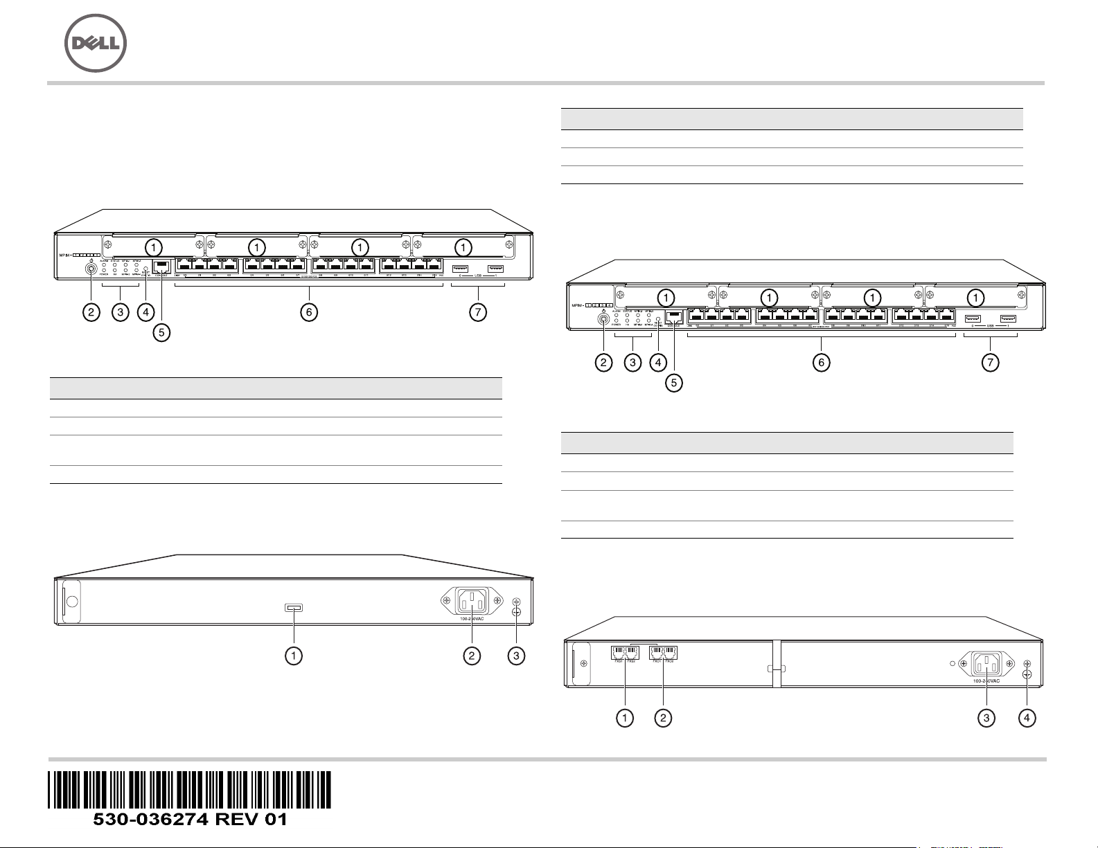
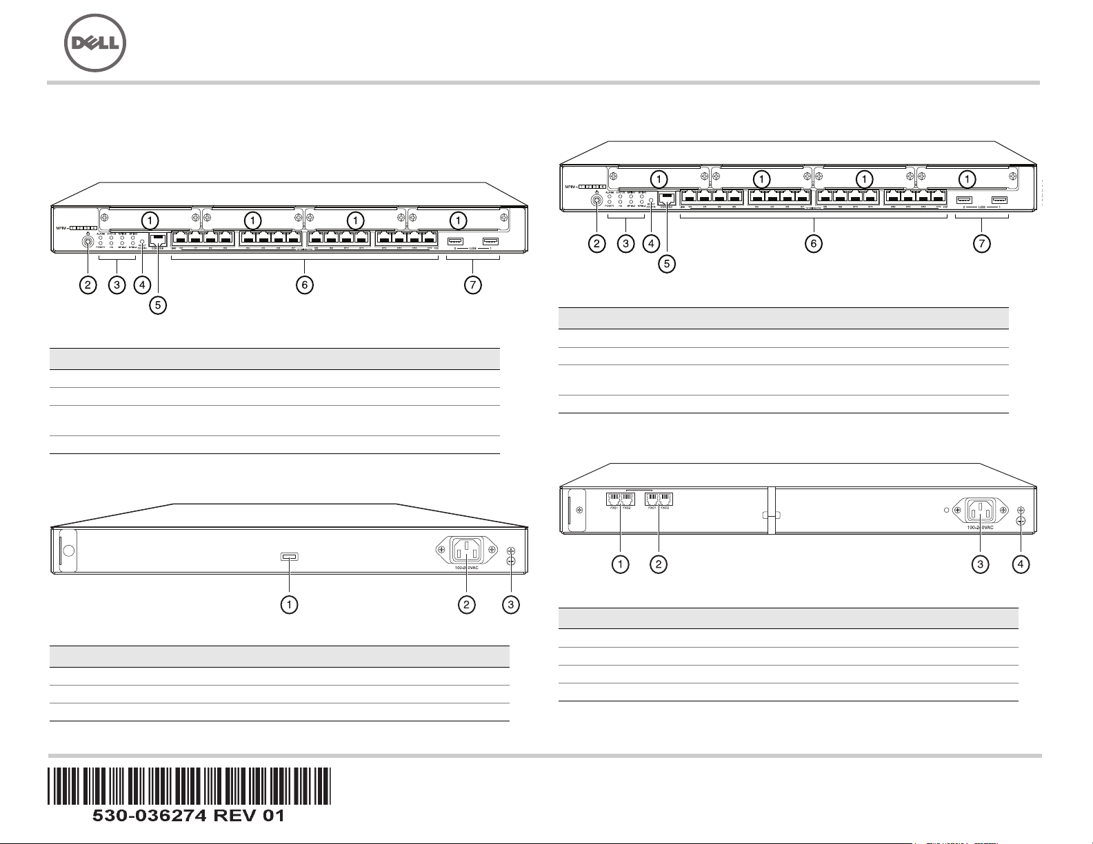
J-SRX240 Services Gateway (J-SRX240B, J-SRX240H) Front Panel
J-SRX240 Services Gateway (J-SRX240B, J-SRX240H, J-SRX240H-POE)
Back Panel
J-SRX240 Services Gateway with Integrated Convergence Services
(J-SRX240H-POE, J-SRX240H-P-MGW) Front Panel
J-SRX240 Services Gateway with Integrated Convergence Services
(J-SRX240H-P-MGW) Back Panel
Callout Description Callout Description
1 Mini-PIM slots 5 Console port
2 Power button 6 Gigabit Ethernet (0/0 to 0/15)
3 LEDs (ALARM, POWER,
STATUS, HA, mPIM)
7 USB ports
4 Reset Config button
Callout Description
1 Cable tie holder
2 Power supply input
3 Grounding point
Callout Description Callout Description
1 Mini-PIM slots 5 Console port
2 Power button 6 Gigabit Ethernet (0/0 to 0/15)
3 LEDs (ALARM, POWER,
STATUS, HA, mPIM)
7 USB ports
4 Reset Config button
037518
Dell PowerConnect J-Series J-SRX240 Services Gateway
Quick Start
Page 2
J-SRX240 Services Gateway Models
The following four models of J-SRX240 Services Gateway are available:
NOTE:
On the J-SRX240H-PoE and J-SRX240H-P-MGW models, Power over Ethernet
(PoE) of 150 watts is supported across all 16 ports (ge-0/0/0 to ge-0/0/15).
Connecting and Configuring the J-SRX240 Services Gateway
Use the instructions below to connect and set up any model of the J-SRX240 Services
Gateway to protect your network. Refer to the LEDs on the front panel of the device to
help you determine the status of the device.
Part 1: Connect the Services Gateway to Earth Ground
1. Obtain a grounding cable—14 AWG single-strand, 4 A—with a ring-type,
vinyl-insulated TV14-6R lug or equivalent attached by a licensed electrician.
2. Connect the grounding cable to a proper earth ground.
3. Place the grounding cable lug over the grounding point on the upper rear of the
chassis, and secure the lug with one 6-32 UNC screw.
Part 2: Connect the Power Cable to the Device
Connect the power cable to the device and a power source. We recommend using a
surge protector. Note the following indications:
POWER LED (green): The device is receiving power.
STATUS LED (green): The device is operating normally.
ALARM LED (amber): The device is operating normally, and may glow amber as a
rescue configuration has not been set. This is not a panic condition.
mPIM LED (off): The Mini-Physical Interface Module (Mini-PIM) is not present or is
not detected by the device. If this LED is green and steadily on, it indicates that the
Mini-PIM is functioning normally.
NOTE:
After a rescue configuration has been set, an amber ALARM LED indicates a
minor alarm, and a solid red ALARM LED indicates that a major problem exists on the
services gateway.
NOTE:
You must allow the device between 5 and 7 minutes to boot up after you have
powered it on. Wait until the STATUS LED is solid green before proceeding to the next
part.
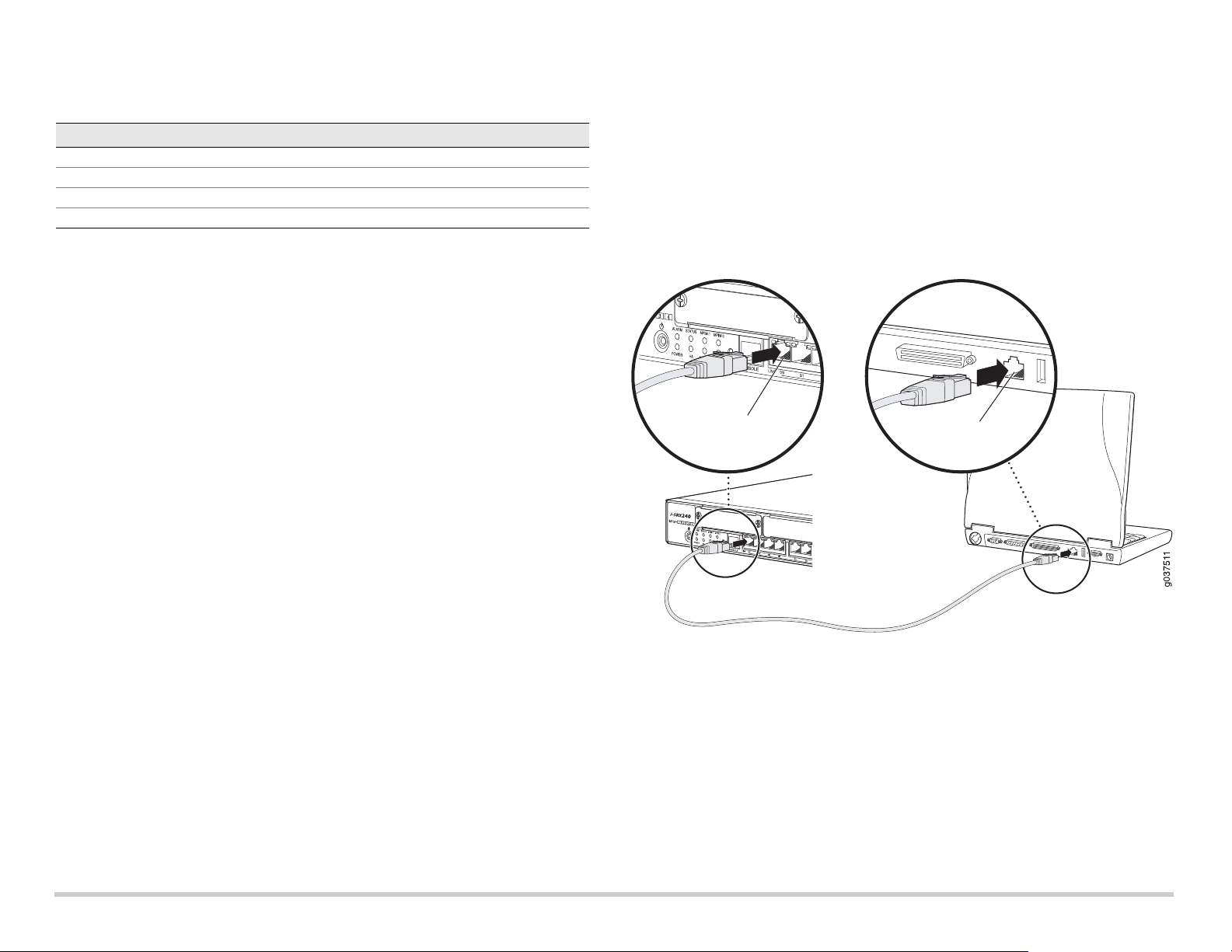
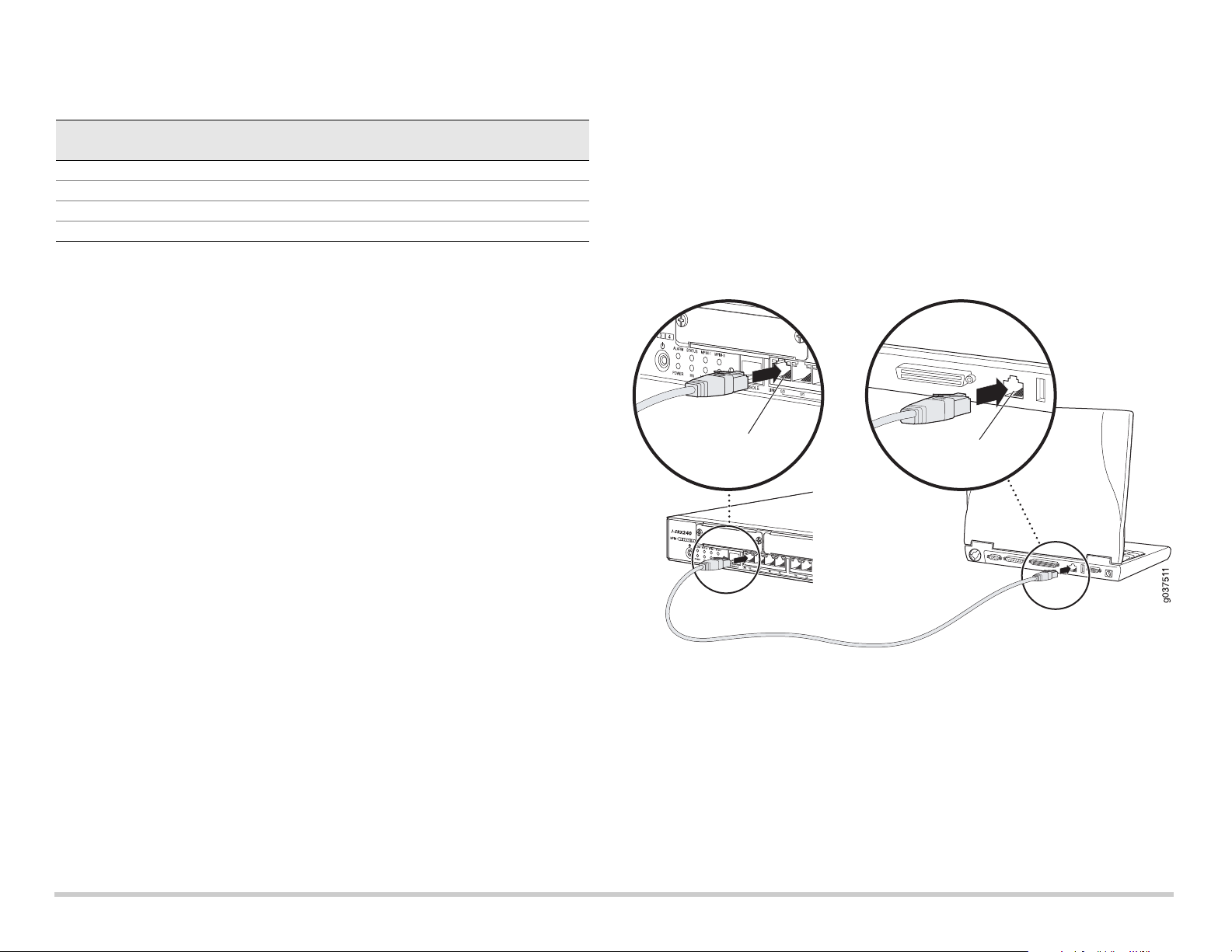
Part 3: Connect the Management Device
Connect the management device to the services gateway using either of the following
methods:
Connect an RJ-45 cable (Ethernet cable) from any one port between ge-0/0/1 and
ge-0/0/15 on the front panel to the Ethernet port on the management device
(workstation or laptop).
We recommend this connection method. If you are using this method to connect,
proceed with Part 4.
Connect an RJ-45 cable (Ethernet cable) from the port labeled CONSOLE to the
supplied DB-9 adapter, which then connects to the serial port on the management
device. (Serial port settings: 9600 8-N-1.)
If you are using this method to connect, proceed with the CLI configuration
instructions available in the Branch SRX Series Services Gateways Golden
Configurations at http://www.juniper.net/us/en/local/pdf/app-notes/3500153-en.pdf.
See the illustration below for details on connecting a management interface:
Callout Description
1 FXS voice port
2 FXO voice port
3 Power supply input
4 Grounding point
Device DDR Memory Power over Ethernet Voice Support
J-SRX240B 512 MB No No
J-SRX240H 1 GB No No
J-SRX240H-POE 1 GB Yes No
J-SRX240H-P-MGW 1 GB Yes Yes

Page 3
Part 4: Understand the Default Configuration Settings
The J-SRX240 Services Gateway is a secure routing device that requires these basic
configuration settings to function properly:
Interfaces must be assigned IP addresses.
Interfaces must be bound to zones.
Policies must be configured between zones to permit/deny traffic.
Source NAT rules must be set.
The device has the following default configuration set when you power it on for the first
time. To be able to use the device, you do not need to perform any initial configuration.
F
ACTORY DEFAULT SETTINGS FOR INTERFACES
FACTORY DEFAULT SETTINGS FOR SECURITY POLICIES
FACTORY DEFAULT SETTINGS FOR NAT RULE
Part 5: Ensure that the Management Device Acquires an IP Address
After connecting the management device to the services gateway, the DHCP server
process on the services gateway will assign an IP address automatically to the
management device. Ensure that the management device acquires an IP address on the
192.168.1/24 subnetwork (other than 192.168.1.1) from the device.
NOTE:
The services gateway functions as a DHCP server and will assign an IP address to
the management device.
If an IP address is not assigned to the management device, manually configure an
IP address in the 192.168.1.0/24 subnetwork. Do not assign the 192.168.1.1 IP
address to the management device, as this IP address is assigned to the device. By
default, the DHCP server is enabled on the L3 VLAN interface, (IRB) vlan.0
(ge-0/0/1 to ge-0/0/15), which is configured with an IP address of 192.168.1.1/24.
When a J-SRX240 Services Gateway is powered on for the first time, it boots using
the factory default configuration.
Part 6: Ensure that an IP Address is Assigned to the Services Gateway
Use one of the following methods to obtain an IP address on the services gateway.
METHOD 1: OBTAINING A DYNAMIC IP ADDRESS ON YOUR SERVICES GATEWAY
Use the ge-0/0/0 port to connect to your Internet Service Provider (ISP). Your ISP
will assign an IP address using the DHCP process.
If you are using this method to obtain an IP address on your services gateway,
proceed with the steps from Part 7 to Part 10 in this document to configure your
device and pass traffic.
Port Label Interface Security Zone DHCP State IP Address
0/0 ge-0/0/0 untrust client unassigned
0/1 to 0/15 ge-0/0/1 to ge-0/0/15 trust server 192.168.1.1/24
Source Zone Destination Zone Policy Action
trust untrust permit
trust trust permit
untrust trust deny
Source Zone Destination Zone Policy Action
trust untrust source NAT to untrust zone interface

Page 4
METHOD 2: OBTAINING A STATIC IP ADDRESS ON YOUR SERVICES GATEWAY
Use the ge-0/0/0 port to connect to your ISP. Your ISP will have provided a static IP
address. You will not receive an IP address using the DHCP process.
If you are using this method to obtain an IP address on your services gateway, follow
the instructions from Part 7 to Part 10 in this document.
Part 7: Access the J-Web Interface
1. Launch a Web browser on the management device.
2. Enter http://192.168.1.1 in the URL address field. The J-Web login page is
displayed.
3. Specify the default user name as root. Do not enter any value in the Password field.
4. Click Log In. The J-Web Initial Setup page is displayed.
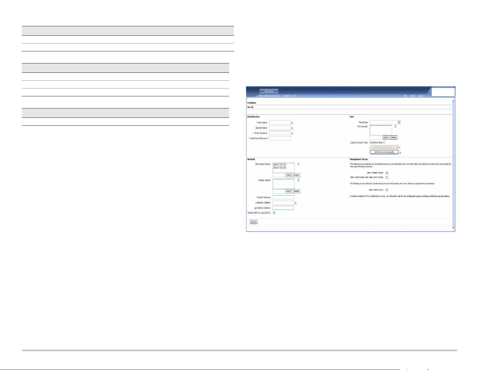
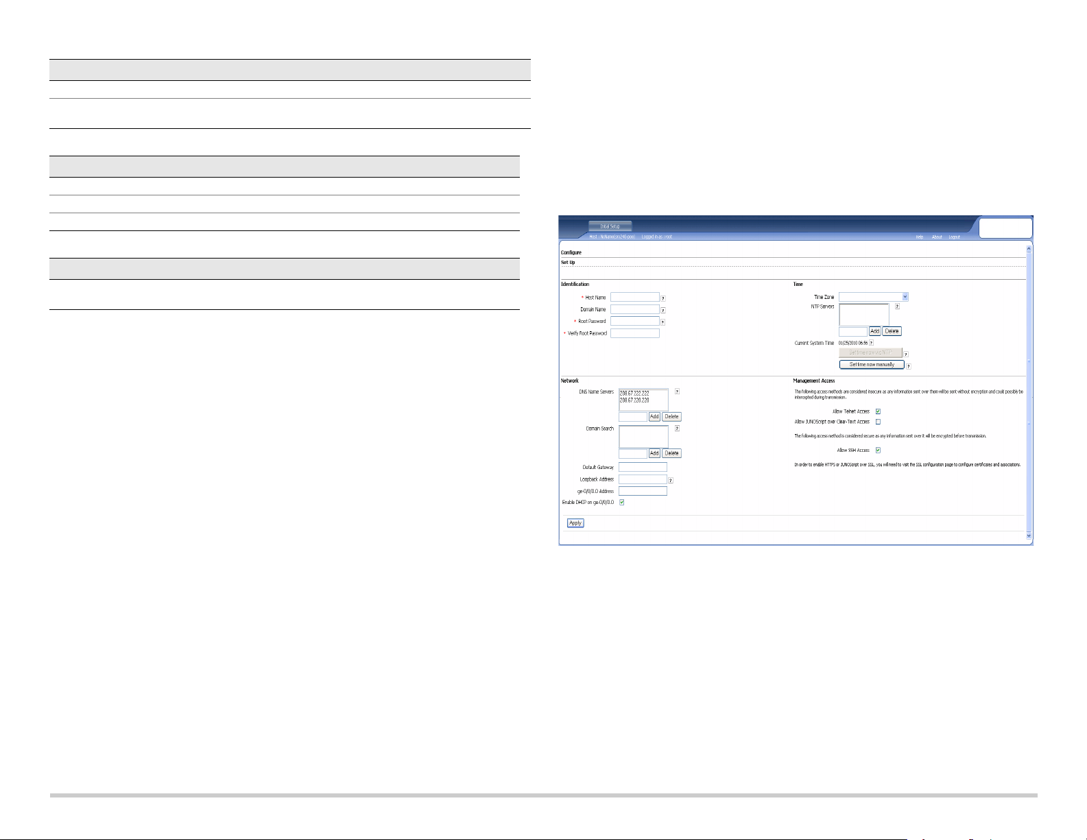
Part 8: Configure the Basic Settings
Configure the basic settings such as Host Name, Domain Name, and Root Password for
your services gateway.
IMPORTANT:
Ensure that you have configured the IP address and root password before
you apply the configuration.
NOTE:
All fields marked with an asterisk (*) are mandatory.
If you have used Method 2 in Part 6 to obtain an IP address on your services gateway,
ensure that you make the following J-Web modifications:
1. Unselect the Enable DHCP on ge-0/0/0.0 check box.
2. Enter the manual IP address provided by your ISP in the ge-0/0/0.0 address field.
The IP address must be entered in the
a.b.c.d/xx
format, where
xx
is the subnet
mask.
3. Enter the IP address of the gateway in the Default Gateway field. The IP address for
the gateway is also provided by the ISP.
4. Enter server names in the DNS name servers field. The server names will be
provided by your ISP.
5. Apply the configuration.
Part 9: Apply the Basic Configuration
1. Click Commit to save the basic configuration.
2. Click Apply to apply the basic configuration.
NOTE:
To make any changes to the interface configuration, see the Branch SRX Series
Services Gateways Golden Configurations at
http://www.juniper.net/us/en/local/pdf/app-notes/3500153-en.pdf.
Part 10: Verify the Configuration
Access http://www.support.dell.com to ensure that you are connected to the internet.
This connectivity ensures that you can pass traffic through the services gateway.
NOTE:
If the http://www.support.dell.com page does not load, verify your configuration
settings, and ensure that you have applied the configuration.
After you have completed these steps, you can pass traffic from any trust port to the
untrust port.
Connecting and Configuring the J-SRX240 Services Gateway with
Integrated Convergence Services
If you have a J-SRX240H-P-MGW model, use the instructions below to configure voice
support on the media gateway and get started using your device to place and receive
calls.
The following table provides an overview of the steps you must follow to configure voice
support on the media gateway.
Step Ta sk Step Task
1 Connect the FXO and FXS ports. 7 Configure the trunk.
2 Access the J-Web interface. 8 Configure trunk groups.
3 Configure the class of restriction. 9 Create the dial plan.
4 Configure the SIP station. 10 Configure the media gateway.
5 Configure the analog station. 11 Configure the survivable call server.
6 Configure the peer call server.

Page 5
Part 1: Connect the FXS and FXO Ports
1. Connect an FXS port (FXS1 or FXS2) on the device to an analog device such as a
telephone, fax, or modem through an RJ-11 cable.
2. Connect an FXO port (FXO1 or FXO2) on the device to the central office (CO)
switches or to a station port on a PSTN through an RJ-11 cable.
3. Connect an Ethernet cable from any of the PoE ports (ge-0/0/0 through ge-0/0/15) to
the VoIP phone.
Part 2: Access the J-Web Interface
1. Launch a Web browser from the management device.
2. Log on using the credentials you set during the initial configuration described in the
“Connecting and Configuring the J-SRX240 Services Gateway” section.
3. The J-Web Dashboard page is displayed.
Part 3: Configure the Class of Restriction
Configure the class of restriction to define the policy dedicated to specifying call type
permissions:
1. Select Configure > Convergence Services > Station > Class of Restriction. The
Class of Restriction Configuration page is displayed.
2. Click Add to create a new class of restriction. The New Class of Restriction page is
displayed.
3. Enter the name in the Class of Restriction field.
4. Click Add to add a new policy to the class of restriction you are creating. The New
Policy Configuration page is displayed.
5. Perform the following actions:
NOTE:
By default, only intra-branch calls and emergency calls are allowed.
Part 4: Configure the SIP Station
NOTE:
For initial configuration of the device, you do not need to configure the station
templates. You can use the default values.
1. Select Configure > Convergence Services > Station. The Station Configuration
page is displayed.
2. Click Add to add the new station and perform the following mandatory basic actions:
You can configure the analog templates to be similar so that they can share a common
configuration.
Part 5: Configure the Analog Station
1. Select Configure > Convergence Services > Station. The Station Configuration
page is displayed.
2. Click Add to add the new station and perform the following mandatory basic actions:
NOTE:
You can configure the individual SIP stations similarly so that they can share a
common configuration.
Part 6: Configure the Peer Call Server
Configure the peer call server that provides call routing and call handling services for the
device:
1. Select Configure > Convergence Services > Call Server. The Peer Call Server
Configuration page is displayed.
2. Perform the following mandatory basic actions:
NOTE:
When configuring the peer call server:
Field Action
Policy Name Specify a name for the policy.
Available Call Types Select the call types applicable to your setup.
Permissions Set permissions (allow or deny) on the selected call types.
Field Action
Name Specify a name for the station.
Extensions Enter the extension number of the station.
Class of Restriction Select the already configured class of restriction.
Template Name Select the already defined station template.
Field Action
Name Specify a name for the station.
Extensions Enter the extension number of the station.
Class of Restriction Select the already configured class of restriction.
Template Name Select the already defined station template.
TDM Interface Specify the type of TDM interface to be configured (FXO, FXS, or T1).
Field Action
Name Specify the name for the peer call server.
PSTN Access
Number
Specify the external PSTN number for the survivable call server to use if it
must contact the PSTN directly.
Address Type Select the address type as either fqdn or ipv4-address.
FQDN Enter the fully qualified domain name.
IP Address Enter the IP address of the peer call server.
Page 6
For the device to authenticate itself with the peer call server, you might need to
provide the device user ID and password details as provided by the peer call
server’s administrator.
You can accept the default values in the Port (5060) and Transport (UDP) fields.
For initial configuration of the device, you do not need to specify the codec. The
default set of codecs is used. By default, codecs are specified in the following order:
711-µ, G711-A, G729AB.
Part 7: Configure a Trunk
Configure a trunk for a PSTN time-division multiplexing (TDM) interface to be used by
the device or the survivable call server to route calls to the destination.
1. Select Configure > Convergence Services > Gateway > Trunks. The New Trunk
Configuration page is displayed.
2. Perform the following actions:
Part 8: Configure the Trunk Groups
A trunk group comprises multiple trunks specified in the order of precedence in which
they must be selected to route a call.
1. Select Configure > Convergence Services > Gateway > Trunk Groups. The
Trunk Group Configuration page is displayed.
2. Click Add to create a new trunk group and perform the following mandatory actions:
Part 9: Create the Dial Plan
Create the dial plan to enable the peer call server to route outbound calls placed from
SIP telephones/analog stations at the branch to its PSTN:
1. Select Configure > Convergence Services > Dial Plan and click on Dial Plan. The
Dial Plan Configuration page is displayed.
2. Click Add to create a new dial plan. The New Dial Plan Configuration page is
displayed.
3. Enter a name in the Dial Plan Name field and click Add. The New Route Pattern
Configuration page displays.
4. Perform the following mandatory basic actions:
NOTE:
You can accept the default values for the Preference and Digit Manipulation fields.
Part 10: Configure the Media Gateway
Configure the media gateway to enable users to place calls within the branch and
externally when the peer call server is accessible to provide call routing and other call
handling services:
1. Select Configure > Convergence Services > Media Gateway > Gateway. The
Media Gateway Configuration page is displayed.
2. Click Add and enter the following mandatory settings:
NOTE:
You can accept the default values in the Port (5060) and Transport (UDP) fields.
Field Action
Trunk Name Enter a name for the trunk.
Trunk Type Select the trunk type (FXO, FXS, or T1).
TDM Interface Select the type of TDM interface to be configured (FXO, FXS, or T1) for
routing certain types of calls.
Field Action
Name Specify a name for the trunk group.
Available Trunks Select the trunks applicable to your setup.
Field Action
Route Pattern Specify the route pattern name.
Call Type Select the call type. The default is trunk-call.
Trunk-groups Select the preconfigured trunk groups to include in the route pattern.
Field Action
Media Gateway Specify the device name.
Call Server Select a peer call with which to associate.
Dial Plan Select a preconfigured dial plan.
Zone Specify the service point for the device’s zone to enable the media gateway
and survivable call server services for the specified zone.
Part 11: Configure the Survivable Call Server
This server assumes the responsibilities of the peer call server when the peer call server
is unreachable:
1. Select Configure > Convergence Services > Call Service. The Survivable Call
Service page is displayed.
2. Click Add to create a new call service and perform the following mandatory basic
actions:
NOTE:
All other parameters required to configure the call service are optional and you
can accept the default values set for these parameters.
Powering Off the Device
You can power off the device in one of the following ways:
Graceful shutdown—Press and immediately release the Power button. The device
begins gracefully shutting down the operating system.
Immediate shutdown—Press the Power button and hold it for 10 seconds. The
device immediately shuts down. Press the Power button again to power on the
device.
NOTE:
You can reboot or halt the system in the J-Web interface by selecting
Maintain > Reboot.
For additional configuration information, see the Branch SRX Series Services Gateways
Golden Configurations at
http://www.juniper.net/us/en/local/pdf/app-notes/3500153-en.pdf.
For detailed software configuration information, see the software documentation
available at http://www.juniper.net/techpubs/software/junos-srx/index.html.
Contacting Dell
For technical support, see http://www.support.dell.com.
Field Action
Call Service Name Specify the name for the call service.
Call Server Select the peer call server name.
Dial Plan Select the preconfigured dial plan to be used for the survivable call server.
Zone Specify the name for the zone.
Information in this document is subject to change without notice. All rights reserved. Reproduction of these materials in any manner whatsoever without the written permission of Juniper Networks is strictly forbidden. Trademarks used
in this text: Dell™, the DELL™ logo, and PowerConnect™ are trademarks of Dell Inc. Juniper Networks® and G33® are registered trademarks of Juniper Networks, Inc. in the United States and other countries. All other trademarks,
service marks, registered trademarks, or registered service marks are the property of their respective owners. Juniper Networks assumes no responsibility for any inaccuracies in this document. Juniper Networks reserves the right to
change, modify, transfer, or otherwise revise this publication without notice. Products made or sold by Juniper Networks or components thereof might be covered by one or more of the following patents that are owned by or licensed to
Juniper Networks: U.S. Patent Nos. 5,473,599, 5,905,725, 5,909,440, 6,192,051, 6,333,650, 6,359,479, 6,406,312, 6,429,706, 6,459,579, 6,493,347, 6,538,518, 6,538,899, 6,552,918, 6,567,902, 6,578,186, and 6,590,785. Copyright ©
2010, Juniper Networks, Inc. All rights reserved. Printed in USA. Part Number: 530-036274 REV 01, July 2010.
使用此快速入門中的說明,協助您將 Dell PowerConnect J-Series J-SRX240 服務閘道連
線至網路。如需詳細資訊,請參閱 J-SRX240 Services Gateway Hardware Guide,網址
為 http://support.dell.com/manuals。(
管理型號為
SRX240)
J-SRX240 Services Gateway (J-SRX240B
、
J-SRX240H)
前面板
J-SRX240
服務閘道
(J-SRX240B
、
J-SRX240H
、
J-SRX240H-POE)
後面板
含整合收斂服務之
J-SRX240
服務閘道
(J-SRX240H-POE
、
J-SRX240H-P-MGW)
前面板
含整合收斂服務之
J-SRX240
服務閘道
(J-SRX240H-P-MGW)
後面板
編號 說明 編號 說明
1
Mini-PIM 插槽
5
主控台連接埠
2
Power 按鈕
6
十億位元乙太網路 (0/0 到 0/15)
3
LED (ALARM、POWER、
STATUS、HA、mPIM)
7
USB 連接埠
4
Reset Config 按鈕
編號 說明
1
纜線束固定器
2
電源供應輸入
3
接地點
037502
編號 說明 編號 說明
1
Mini-PIM 插槽
5
主控台連接埠
2
Power 按鈕
6
十億位元乙太網路 (0/0 到 0/15)
3
LED (ALARM、POWER、
STATUS、HA、mPIM)
7
USB 連接埠
4
Reset Config 按鈕
編號 說明
1
FXS 語音連接埠
2
FXO 語音連接埠
3
電源供應輸入
4
接地點
g037518
Dell PowerConnect J-Series J-SRX240 服務閘道快速入門
第 2 頁
J-SRX240 服務閘道機型
提供以下四種 J-SRX240 服務閘道機型:
請注意
:
在 J-SRX240H-PoE 與 J-SRX240H-P-MGW 機型上,全部 16 個連接埠 (ge-0/0/0
到 ge-0/0/15) 皆支援 150 瓦的乙太網路供電 (PoE)。
連接與組態 J-SRX240 服務閘道
使用下列說明來連接及設定任何機型的 J-SRX240 服務閘道,以保護您的網路。請參考
裝置前面板上的 LED,以協助您確定裝置的狀態。
第
1
部分:將服務閘道連接至地面
1. 取得一條接地纜線 (14 AWG 單股,4 A),並由授權的電工將纜線與圓形乙烯基絕緣
TV14-6R 接線片或同型接線片連接。
2. 將接地纜線連接到正確的接地點。
3. 將接地纜線接線片置於機箱背面上方的接地點,然後使用一個 6-32 UNC 螺絲來固定
接線片。
第
2
部分:將電源纜線連接至裝置
將電源纜線連接至裝置與電源。我們建議您使用突波保護器。請注意下列指示:
POWER LED ( 綠色 ):裝置已通電。
STATUS LED ( 綠色):裝置運作正常。
ALARM LED ( 琥珀黃色 ):裝置運作正常,此外若未設定救援組態,則可能會亮起琥
珀黃色燈。這並不屬於緊急情況。
mPIM LED ( 熄滅 ):Mini-Physical Interface Module (Mini-PIM) 不存在,或裝置未偵測
到。如果此 LED 為綠色且恆亮,表示 Mini-PIM 功能正常。
請注意
:
設定完救援組態後,琥珀黃色 ALARM LED 表示輕微警示,而紅色 ALARM LED
表示服務閘道存在嚴重問題。
請注意
:
在開啟裝置電源後,必須讓裝置有 5 到 7 分鐘的啟動時間。請靜待 STATUS LED
穩定亮起綠燈,然後再繼續下一個部分。
第
3
部分:連接管理裝置
使用以下其中一種方法將管理裝置連接至服務閘道:
用 RJ-45 纜線 ( 乙太網路纜線 ) 將前面板上 ge-0/0/1 到 ge-0/0/15 之間的任何一個連
接埠與管理裝置 ( 工作站或筆記型電腦 ) 上的乙太網路連接埠連在一起。
我們建議您使用這種連接方法。如果使用此方法進行連接,請繼續第 4 部分。
用 RJ-45 纜線 ( 乙太網路纜線 ) 將標有 CONSOLE 的連接埠與隨附的 DB-9 配接卡相
連,然後將其連接至管理裝置上的序列連接埠。( 序列連接埠設定:9600 8-N-1。)
如果您使用此方法進行連接,請參閱 Branch SRX Series Services Gateways
Golden Configurations ( 網址為
http://www.juniper.net/us/en/local/pdf/app-notes/3500153-en.pdf) 中的 CLI 組態說明
繼續操作。
如需連接管理介面的詳細資訊,請參閱下圖 :
第
4
部分:瞭解預設組態設定
J-SRX240 服務閘道是一個安全路由裝置,其需要這些基本組態設定才能正常運作 :
必須為介面指派 IP 位址。
必須將介面連接至區域。
必須在區域間組態政策,以允許 / 拒絕通訊流量。
必須設定來源 NAT 規則。
第一次開啟裝置電源時,會設定下列預設組態。您不必執行任何初始組態便可使用裝置。
裝置 DDR 記憶體 乙太網路供電 語音支援
J-SRX240B 512 MB
否否
J-SRX240H 1 GB
否否
J-SRX240H-POE 1 GB
是否
J-SRX240H-P-MGW 1 GB
是是
⮹偁恾抲㘴⩯
⮹偁恾抲㘴⩯
5-儫偩

菴 3 珜
介面的出廠預設設定
安全性政策的出廠預設設定
NAT
規則的出廠預設設定
第
5
部分:確保管理裝置取得
IP
位址
將管理裝置連接至服務閘道後,服務閘道上的 DHCP 伺服器程序會將 IP 位址自動指派給
管理裝置。確保管理裝置從裝置取得 192.168.1/24 子網路 ( 而不是 192.168.1.1) 上的 IP
位址。
請注意
:
服務閘道的功能類似於 DHCP 伺服器,而且會為管理裝置指派 IP 位址。
如果未將 IP 位址指派給管理裝置,請手動組態 192.168.1.0/24 子網路中的一個 IP
位址。請勿將 192.168.1.1 IP 位址指派給管理裝置,因為此 IP 位址已指派給裝置。
依預設,DHCP 伺服器在 L3 VLAN 介面,即 (IRB) vlan.0 (ge-0/0/1 到 ge-0/0/15) 啟
用,它透過 IP 位址 192.168.1.1/24 組態。
第一次開啟 J-SRX240 服務閘道電源時,其會使用出廠預設組態啟動。
第
6
部分:確認已將
IP
位址指派給服務閘道
使用以下其中一種方法取得服務閘道的 IP 位址。
方法
1
:取得服務閘道的動態
IP
位址
使用 ge-0/0/0 連接埠連線至「網際網路服務供應商」(ISP)。ISP 會使用 DHCP 程序
指派一個 IP 位址。
如果您使用此方法取得服務閘道的 IP 位址,請繼續執行本文件中第 7 到第 10 部分
的步驟,以設定您的裝置及傳送通訊流量。
方法
2
:取得服務閘道的靜態
IP
位址
使用 ge-0/0/0 連接埠連線至 ISP。ISP 將提供一個靜態 IP 位址。將不會接收到使用
DHCP 程序指派的 IP 位址。
如果您使用此方法取得服務閘道的 IP 位址,請遵循本文件中第 7 到第 10 部分的
指示。
第
7
部分:存取
J-Web
介面
1. 在管理裝置上啟動 Web 瀏覽器。
2. 在 URL 位址欄位中輸入 http://192.168.1.1。接著會顯示 J-Web 登入頁面。
3. 將預設使用者名稱指定為 root。請勿在 Password 欄位中輸入任何值。
4. 按一下 Log In。會顯示 J-Web Initial Setup 頁面。
第
8
部分:進行基本設定
為服務閘道組態基本設定,例如 Host Name、Domain Name 與 Root Password。
重要
:
確認您在套用組態之前,已設定 IP 位址與根密碼。
請注意
:
標記星號 (*) 的所有欄位皆為必填欄位。
如果您已使用第 6 部分的方法 2 取得服務閘道的 IP 位址,請務必修改下列的 J-Web
內容:
1. 取消選擇 Enable DHCP on ge-0/0/0.0 核取方塊。
2. 在 ge-0/0/0.0 位址欄位中輸入 ISP 提供給您的手動 IP 位址。必須以
a.b.c.d/xx
的格式
輸入此 IP 位址,其中
xx
是子網路遮罩。
3. 在 Default Gateway 欄位中輸入閘道的 IP 位址。閘道的 IP 位址也由 ISP 提供。
連接埠標籤 介面 安全區 DHCP 狀態 IP 位址
0/0 ge-0/0/0 untrust
用戶端 未指派
0/1 到 0/15 ge-0/0/1 到 ge-0/0/15
trust
伺服器
192.168.1.1/24
來源區 目的區 政策動作
trust untrust
允許
trust trust
允許
untrust trust
拒絕
來源區 目的區 政策動作
trust untrust
來源 NAT 到 untrust 區域介面

菴 4 珜
4. 在 DNS name servers 欄位中輸入伺服器名稱。伺服器名稱由您的 ISP 提供。
5. 套用組態。
第
9
部分:套用基本組態
1. 按一下 Commit 來儲存基本組態。
2. 按一下 Apply 來套用基本組態。
請注意
:
若要對介面組態進行任何變更,請參閱 Branch SRX Series Services Gateways
Golden Configurations,網址為
http://www.juniper.net/us/en/local/pdf/app-notes/3500153-en.pdf。
第
10
部分:驗證組態
存取 http://www.support.dell.com,以確保您已連線至網際網路。此連線可確保您可以透
過服務閘道傳送通訊流量。
請注意
:
如果 http://www.support.dell.com 頁面未載入,請驗證組態設定,並確保您已套用
該組態。
完成這些步驟後,您可以將通訊流量從任何 trust 連接埠傳送至 untrust 連接埠。
連接與組態含整合收斂服務的 J-SRX240 服務閘道
如果您擁有 J-SRX240H-P-MGW 機型,請使用下列指示組態媒體閘道的語音支援,並開
始使用您的裝置來撥打與接聽電話。
下表概述了在組態媒體閘道的語音支援時,您必須遵循的步驟。
第
1
部分:連接
FXS
與
FXO
連接埠
1. 透過 RJ-11 纜線將裝置上的 FXS 連接埠 (FXS1 或 FXS2) 連接至類比裝置,例如電
話、傳真或數據機。
2. 透過 RJ-11 纜線將裝置上的 FXO 連接埠 (FXO1 或 FXO2) 連接至總公司 (CO) 交換
機,或 PSTN 上的工作站連接埠。
3. 透過乙太網路纜線將任一 PoE 連接埠 (ge-0/0/0 到 ge-0/0/15) 連接至 VoIP 電話。
第
2
部分:存取
J-Web
介面
1. 從管理裝置啟動 Web 瀏覽器。
2. 使用您在初始組態期間設定的驗證資料來登入,如 「連接與組態 J-SRX240 服務閘
道」一節中所述。
3. 會顯示 J-Web Dashboard 頁面。
第
3
部分:組態限制類別
組態限制類別,以定義專用於指定呼叫類型權限的政策 :
1. 選擇 Configure > Convergence Services > Station > Class of Restriction。會顯
示 Class of Restriction Configuration 頁面。
2. 按一下 Add,建立新的限制類別。會顯示 New Class of Restriction 頁面。
3. 在 Class of Restriction 欄位中,輸入名稱。
4. 按一下 Add,將新政策新增至您要建立的限制類別中。會顯示 New Policy
Configuration 頁面。
5. 執行下列動作 :
請注意
:
依預設,僅允許分公司內部的呼叫與緊急呼叫。
第
4
部分:組態
SIP
工作站
請注意
:
針對裝置的初始組態,您不必組態工作站範本。您可以使用預設值。
1. 選擇 Configure > Convergence Services > Station。會顯示 Station Configuration
頁面。
2. 按一下 Add,新增工作站並執行下列必需的基本動作 :
您可以將類比範本組態為類似範本,以便其能夠共享通用的組態。
第
5
部分:組態類比工作站
1. 選擇 Configure > Convergence Services > Station。會顯示 Station Configuration
頁面。
2. 按一下 Add,新增工作站並執行下列必需的基本動作 :
步驟 工作 步驟 工作
1
連接 FXO 與 FXS 連接埠。
7
組態中繼。
2
存取 J-Web 介面。
8
組態中繼群組。
3
組態限制類別。
9
建立撥號對應表。
4
組態 SIP 工作站。
10
組態媒體閘道。
5
組態類比工作站。
11
組態可長期有效的呼叫伺服器。
6
組態對等呼叫伺服器。
欄位 動作
Policy Name
為政策指定名稱。
Available Call Types
選擇適用於您的設定的呼叫類型。
Permissions
設定所選呼叫類型的權限 ( 允許或拒絕 )。
欄位 動作
Name
為工作站指定名稱。
Extensions
輸入工作站的分機號碼。
Class of Restriction
選擇已組態的限制類別。
Template Name
選擇已定義的工作站範本。
第 5 頁
請注意
:
您可以使用類似方式組態個別 SIP 工作站,以便其能夠共享通用的組態。
第
6
部分:組態對等呼叫伺服器
組態為裝置提供呼叫路由與呼叫處理服務的對等呼叫伺服器 :
1. 選擇 Configure > Convergence Services > Call Server。會顯示 Peer Call Server
Configuration 頁面。
2. 執行下列必需的基本動作 :
請注意
:
組態對等呼叫伺服器時 :
針對要使用對等呼叫伺服器來驗證其自身的裝置,您可能需要提供對等呼叫伺服器的
管理員所提供的裝置使用者 ID 與密碼詳細資訊。
您可以接受 Port (5060) 與 Transport (UDP) 欄位中的預設值。
針對裝置的初始組態,您不必指定轉碼器。會使用預設的轉碼器集合。依預設,會透
過下列順序來指定轉碼器 :711-µ、G711-A、G729AB。
第
7
部分:組態中繼
為裝置或長期有效的呼叫伺服器要使用的 PSTN 分時多工法 (TDM) 介面組態中繼,以將
呼叫路由至目的地。
1. 選擇 Configure > Convergence Services > Gateway > Trunks。會顯示 New
Trunk Configuration 頁面。
2. 執行下列動作 :
第
8
部分:組態中繼群組
中繼群組由多個中繼組成,這些中繼將依照其在路由呼叫時必須遵循的優先順序來指定。
1. 選擇 Configure > Convergence Services > Gateway > Trunk Groups。會顯示
Trunk Group Configuration 頁面。
2. 按一下 Add,建立新的中繼群組並執行下列必需動作 :
第
9
部分:建立撥號對應表
建立撥號對應表,使對等呼叫伺服器將分公司的 SIP 電話 / 類比工作站撥打的外線電話路
由至其 PSTN:
1. 選擇 Configure > Convergence Services > Dial Plan,然後按一下 Dial Plan。會
顯示 Dial Plan Configuration 頁面。
2. 按一下 Add,建立新的撥號對應表。會顯示 New Dial Plan Configuration 頁面。
3. 在 Dial Plan Name 欄位中輸入名稱,然後按一下 Add。會顯示 New Route Pattern
Configuration 頁面。
4. 執行下列必需的基本動作 :
請注意
:
您可以接受 Preference 與 Digit Manipulation 欄位的預設值。
第
10
部分:組態媒體閘道
在可以存取對等呼叫伺服器來提供呼叫路由及其他呼叫處理服務的情況下,組態媒體閘
道,讓使用者可以在分公司內部或外部撥打電話 :
1. 選擇 Configure > Convergence Services > Media Gateway > Gateway。會顯示
Media Gateway Configuration 頁面。
2. 按一下 Add,然後輸入下列必需設定 :
欄位 動作
Name
為工作站指定名稱。
Extensions
輸入工作站的分機號碼。
Class of Restriction
選擇已組態的限制類別。
Template Name
選擇已定義的工作站範本。
TDM Interface
指定要組態的 TDM 介面類型 (FXO、FXS 或 T1)。
欄位 動作
Name
為對等呼叫伺服器指定名稱。
PSTN Access
Number
為要使用的長期有效的呼叫伺服器指定外部 PSTN 號碼 ( 若其必須直接聯
絡 PSTN)。
Address Type
選擇位址類型作為 fqdn 或 ipv4-address。
FQDN
輸入完全合格的網域名稱。
IP Address
輸入對等呼叫伺服器的 IP 位址。
欄位 動作
Trunk Name
輸入中繼名稱。
Trunk Type
選擇中繼類型 (FXO、FXS 或 T1)。
TDM Interface
選擇要組態的 TDM 介面類型 (FXO、FXS 或 T1),以路由特定類型的呼叫。
欄位 動作
Name
為中繼群組指定名稱。
Available Trunks
選擇適用於設定的中繼。
欄位 動作
Route Pattern
指定路由模式名稱。
Call Type
選擇呼叫類型。預設為中繼呼叫。
Trunk-groups
選擇要包括在路由模式中的預先組態的中繼群組。

菴 6 珜
請注意
:
您可以接受 Port (5060) 與 Transport (UDP) 欄位中的預設值。
第
11
部分:組態長期有效的呼叫伺服器
無法連線對等呼叫伺服器時,此伺服器會接手對等呼叫伺服器的工作 :
1. 選擇 Configure > Convergence Services > Call Service。會顯示 Survivable Call
Service 頁面。
2. 按一下 Add,建立新的呼叫服務並執行下列必需的基本動作 :
請注意
:
組態呼叫服務所需的其他所有參數都是可選參數,您可以接受為這些參數設定的
預設值。
關閉裝置電源
您可以使用下列方式之一來關閉裝置電源 :
平穩關閉 - 按下並立即鬆開 Power。裝置會開始平穩關閉作業系統。
立即關閉 - 按住 Power 10 秒鐘。裝置會立即關閉。再次按下 Power 可開啟裝置電源。
請注意
:
透過選擇 Maintain > Reboot,您可以在 J-Web 介面中重新啟動或暫停系統。
如需其他組態資訊,請參閱 Branch SRX Series Services Gateways Golden
Configurations,網址為
http://www.juniper.net/us/en/local/pdf/app-notes/3500153-en.pdf。
如需詳細的軟體組態資訊,請參閱軟體文件,網址
http://www.juniper.net/techpubs/software/junos-srx/index.html。
聯絡 Dell
如需技術支援,請參閱 http://www.support.dell.com。
欄位 動作
Media Gateway
指定裝置名稱。
Call Server
選擇要關聯的對等呼叫伺服器。
Dial Plan
選擇預先組態的撥號對應表。
Zone
為裝置的區域指定服務點,以啟用指定區域的媒體閘道與長期有效的呼叫伺服
器服務。
欄位 動作
Call Service Name
為呼叫服務指定名稱。
Call Server
選擇對等呼叫伺服器的名稱。
Dial Plan
選擇要用於長期有效的呼叫伺服器之預先組態的撥號對應表。
Zone
為區域指定名稱。
本文件中的資訊如有變更,恕不另行通知。保留所有權利。未經 Juniper Networks 書面許可,嚴格禁止以任何方式複製這些資料。本文中所使用的商標:Dell™、DELL™ 標誌和 PowerConnect™ 為 Dell Inc. 的商標。Juniper
Networks® 和 G33® 為 Juniper Networks, Inc. 在美國與其他國家 / 地區的註冊商標。所有其他商標、服務標記、註冊商標或註冊服務標記都屬於其個別擁有者的財產。Juniper Networks 對本文件中的任何錯誤,不承擔任何責任。
Juniper Networks 保留對本出版物進行變更、修改、轉印或其他修訂而不另行通知的權利。Juniper Networks 製造或銷售的產品或其中的元件可能涵蓋於下列一或多個由 Juniper Networks 所有或 Juniper Networks 已獲授權的專利:美
國專利號 5,473,599、5,905,725、5,909,440、6,192,051、6,333,650、6,359,479、6,406,312、6,429,706、6,459,579、6,493,347、6,538,518、6,538,899、6,552,918、6,567,902、6,578,186 及 6,590,785。版權所有 © 2010,
Juniper Networks, Inc. 保留所有權利。美國印刷。產品編號:530-036274-ZH-HANT 修訂本 01,2010 年 7 月

按照本快速入门中的说明进行操作,即可帮助您将 Dell PowerConnect J 系列 J-SRX240
服务网关连接到网络。有关详细信息,请参阅 J-SRX240 Services Gateway Hardware
Guide,网址:http://support.dell.com/manuals。
(规范型号
SRX240
)
J-SRX240
服务网关
(J-SRX240B
、
J-SRX240H)
前面板
J-SRX240
服务网关
(J-SRX240B
、
J-SRX240H
、
J-SRX240H-POE)
后面板
集成融合服务的
J-SRX240
服务网关
(J-SRX240H-POE
、
J-SRX240H-P-MGW)
前面板
集成融合服务的
J-SRX240
服务网关
(J-SRX240H-P-MGW)
后面板
编号 说明 编号 说明
1
小型 PIM 插槽
5
控制台端口
2
Power 按钮
6
千兆位以太网 (0/0 至 0/15)
3
LED (ALARM、 POWER、
STATUS、 HA 和 mPIM)
7
USB 端口
4
Reset Config 按钮
编号 说明
1
电缆固定夹
2
电源输入
3
接地点
037502
编号 说明 编号 说明
1
小型 PIM 插槽
5
控制台端口
2
Power 按钮
6
千兆位以太网 (0/0 至 0/15)
3
LED (ALARM、 POWER、
STATUS、 HA 和 mPIM)
7
USB 端口
4
Reset Config 按钮
编号 说明
1
FXS 语音端口
2
FXO 语音端口
3
电源输入
4
接地点
g037518
Dell PowerConnect J 系列 J-SRX240 服务网关快速入门
第 2 页
J-SRX240 服务网关型号
提供以下四种型号的 J-SRX240 服务网关:
注意:
对于 J-SRX240H-PoE 和 J-SRX240H-P-MGW 型号,所有 16 个端口 (ge-0/0/0
至 ge-0/0/15)均支持 150W 以太网供电 (PoE)。
连接和配置 J-SRX240 服务网关
按照下面的说明连接和设置任何型号的 J-SRX240 服务网关以保护网络。参照设备前面
板上的 LED 来帮助您确定设备的状态。
第
1
部分:将服务网关接地
1. 获取接地电缆—14 AWG 单线, 4 A—带环状、乙烯绝缘 TV14-6R 接线片或同等电
缆,由授权电工接线。
2. 将接地电缆适当接地。
3. 将接地电缆接线片置于机箱背面上方的接地点,然后使用一个 6-32 UNC 螺钉来固定
接线片。
第
2
部分:将电源线连接到设备
将电源线连接到设备和电源。我们建议使用电涌保护器。请注意以下指示 :
POWER LED ( 绿色 ):设备通电。
STATUS LED ( 绿色 ):设备正常工作。
ALARM LED ( 琥珀黄色 ):设备正常工作,但可能由于未设置救援配置而发出琥珀色
黄光。这并不是紧急情况。
mPIM LED (关闭):小型物理接口模块 (Mini-PIM) 不存在或没有被设备检测到。如
果该 LED 为绿色常亮,则表示 Mini-PIM 工作正常。
注意:
设置完救援配置后,琥珀黄色的 ALARM LED 表示不严重的警告,而红色常亮的
ALARM LED 表示服务网关存在严重问题。
注意:
接通电源后,必须等待 5 至 7 分钟的设备启动时间。请等待至 STATUS LED 变为
绿色常亮,再执行下一部分。
第
3
部分:连接管理设备
使用以下任一方法将管理设备连接到服务网关:
将 RJ-45 电缆(以太网电缆) 从前面板上 ge-0/0/1 至 ge-0/0/15 中的任一端口连接到管
理设备 ( 工作站或便携式计算机 ) 上的以太网端口。
我们建议采用这种连接方法。如果您使用此方法进行连接,请继续第 4 部分。
将 RJ-45 电缆(以太网电缆 )从标有 CONSOLE 的端口连接到提供的 DB-9 适配器,然
后将其连接到管理设备上的串行端口。(串行端口设置:9600 8-N-1。)
如果使用此方法进行连接,请继续执行 Branch SRX Series Services Gateways
Golden Configurations 中提供的 CLI 配置说明,该文档的网址为
http://www.juniper.net/us/en/local/pdf/app-notes/3500153-en.pdf。
有关连接管理接口的详细信息,请参阅下图:
第
4
部分:了解缺省配置设置
J-SRX240 服务网关是需要进行以下基本配置设置才能正常运行的安全路由设备:
必须为接口分配 IP 地址。
必须将接口绑定到区段。
必须配置区段间的策略以允许 / 拒绝信息流。
必须设置源 NAT 规则。
首次接通电源时,设备已设置以下缺省配置。无需进行任何初始配置即可使用设备。
设备 DDR 内存 以太网供电 语音支持
J-SRX240B 512 MB
否否
J-SRX240H 1 GB
否否
J-SRX240H-POE 1 GB
是否
J-SRX240H-P-MGW 1 GB
是是
ⅴ⮹几䵾♲
ⅴ⮹几䵾♲
5-䟄冕
第 3 页
接口的出厂缺省设置
安全策略的出厂缺省设置
NAT
规则的出厂缺省设置
第
5
部分:确保管理设备获得
IP
地址
将管理设备连接到服务网关后,服务网关上的 DHCP 服务器进程会自动为管理设备分配
一个 IP 地址。确保管理设备能从该设备获得 192.168.1/24 子网 (而不是 192.168.1.1)
上的 IP 地址。
注意:
服务网关起着 DHCP 服务器的作用,将会给管理设备分配 IP 地址。
如果未给管理设备分配 IP 地址,请手动配置 192.168.1.0/24 子网中的 IP 地址。不
要给管理设备分配 192.168.1.1 IP 地址,因为此 IP 地址已分配给该设备。缺省情况
下, DHCP 服务器在 L3 VLAN 接口 (IRB) vlan.0 (ge-0/0/1 至 ge-0/0/15) 上处于启用
状态,该接口的 IP 地址配置为 192.168.1.1/24。
首次接通 J-SRX240 服务网关的电源时,其会使用出厂缺省配置启动。
第
6
部分:确保已将
IP
地址分配给服务网关
使用以下方法之一在服务网关上获得 IP 地址。
方法
1
:在服务网关上获取动态
IP
地址
使用 ge-0/0/0 端口连接到互联网服务提供商 (ISP)。ISP 将使用 DHCP 进程分配一个
IP 地址。
如果您使用此方法获得服务网关的 IP 地址,请继续本文档第 7 部分至第 10 部分中
的步骤来配置设备和传送信息流。
方法
2
:在服务网关上获得静态
IP
地址
使用 ge-0/0/0 端口连接到 ISP。 ISP 将提供一个静态 IP 地址。使用 DHCP 进程不会
收到 IP 地址。
如果您使用此方法获得服务网关的 IP 地址,请按照本文档第 7 部分至第 10 部分中
的说明进行操作。
第
7
部分:访问
J-Web
界面
1. 在管理设备上启动 Web 浏览器。
2. 在 URL 地址字段中输入 http://192.168.1.1。将显示 J-Web 登录页面。
3. 指定缺省用户名为 root。不要在 Password 字段中输入任何值。
4. 单击 Log In。将显示 J-Web Initial Setup 页面。
第
8
部分:配置基本设置
配置服务网关的基本设置, Host Name, Domain Name 和 Root Password。
重要:
确保在应用配置之前已配置了 IP 地址和根密码。
注意:
所有标有星号 (*) 的字段均为必填字段。
如果您已使用第 6 部分中的方法 2 获取服务网关的 IP 地址,请确保进行以下 J-Web
修改:
1. 取消选中 Enable DHCP on ge-0/0/0.0 复选框。
2. 在 ge-0/0/0.0 地址字段中输入 ISP 提供的手动 IP 地址。必须以
a.b.c.d/xx
的格式输入
IP 地址,其中
xx
为子网掩码。
3. 在 Default Gateway 字段中输入网关的 IP 地址。网关的 IP 地址同样由 ISP 提供。
端口标签 接口 安全区段 DHCP 状态 IP 地址
0/0 ge-0/0/0 untrust
客户端 未指派
0/1 至 0/15 ge-0/0/1 至 ge-0/0/15
trust
服务器
192.168.1.1/24
源区段 目的区段 策略动作
trust untrust
允许
trust trust
允许
untrust trust
拒绝
源区段 目的区段 策略动作
trust untrust
源 NAT 到 untrust 区段接口

第 4 页
4. 在 DNS name servers 字段中输入服务器名称。服务器名称将由 ISP 提供。
5. 应用配置。
第
9
部分:应用基本配置
1. 单击 Commit 保存基本配置。
2. 单击 Apply 应用基本配置。
注意:
要对接口配置进行任何更改,请参阅 Branch SRX Series Services Gateways
Golden Configurations,网址为
http://www.juniper.net/us/en/local/pdf/app-notes/3500153-en.pdf。
第
10
部分:验证配置
访问 http://www.support.dell.com 以确保您已连接到 Internet。该连通性确保您可通过服
务网关传送信息流。
注意:
如果 http://www.support.dell.com 页面未加载,请检查配置设置并确保已应用
配置。
完成这些步骤后,可以将信息流从任何 trust 端口传送到 untrust 端口。
对集成融合服务的 J-SRX240 服务网关进行连接和配置
如果您拥有 J-SRX240H-P-MGW 型号,请使用下面的说明在媒体网关上配置语音支持并
开始使用设备发出和接收呼叫。
下表概述了在媒体网关上配置语音支持所必须遵守的步骤。
第
1
部分:连接
FXS
和
FXO
端口
1. 通过 RJ-11 电缆将设备上的 FXS 端口 (FXS1 或 FXS2) 连接到模拟设备,例如电话、
传真或调制解调器。
2. 通过 RJ-11 电缆将设备上的 FXO 端口 (FXO1 或 FXO2) 连接到总部 (CO) 交换机或
PSTN 上的站端口。
3. 将以太网电缆从任一 PoE 端口 (ge-0/0/0 至 ge-0/0/15) 连接到 VoIP 电话。
第
2
部分:访问
J-Web
界面
1. 从管理设备启动 Web 浏览器。
2. 使用在初始配置 ( 在 “连接和配置 J-SRX240 服务网关”部分中介绍 ) 期间设置的凭
证登录。
3. 即会显示 J-Web Dashboard 页面。
第
3
部分:配置限制分类
配置限制分类以定义专用于指定呼叫类型权限的策略:
1. 选择 Configure > Convergence Services > Station > Class of Restriction。将显
示 Class of Restriction Configuration 页面。
2. 单击 Add 创建新限制分类。将显示 New Class of Restriction 页面。
3. 在 Class of Restriction 字段中输入名称。
4. 单击 Add 将新策略添加到要创建的限制分类。将显示 New Policy Configuration
页面。
5. 执行下列操作:
注意:
缺省情况下,只允许分公司内部呼叫和紧急呼叫。
第
4
部分:配置
SIP
站
注意:
对于设备的初始配置,无需配置站模板。可以使用缺省值。
1. 选择 Configure > Convergence Services > Station。将显示 Station Configuration
页面。
2. 单击 Add 添加新站,然后执行以下必需的基本操作:
可以按同样方式配置模拟模板,以便其可共享通用配置。
第
5
部分:配置模拟站
1. 选择 Configure > Convergence Services > Station。将显示 Station Configuration
页面。
2. 单击 Add 添加新站,然后执行以下必需的基本操作:
步骤 任务 步骤 任务
1
连接 FXO 和 FXS 端口。
7
配置中继。
2
访问 J-Web 界面。
8
配置中继组。
3
配置限制分类。
9
创建拨号计划。
4
配置 SIP 站。
10
配置媒体网关。
5
配置模拟站。
11
配置可存活呼叫服务器。
6
配置对等方呼叫服务器。
字段 操作
Policy Name
指定策略的名称。
Available Call Types
选择适用于设置的呼叫类型。
Permissions
设置所选呼叫类型的权限 (允许或拒绝)。
字段 操作
Name
指定站的名称。
Extensions
输入站的扩展编号。
Class of Restriction
选择已配置的限制分类。
Template Name
选择已定义的站模板。

第 5 页
注意:
可以按同样方式配置各个 SIP 站,以便其可共享通用配置。
第
6
部分:配置对等方呼叫服务器
配置为设备提供呼叫路由和呼叫处理服务的对等方呼叫服务器:
1. 选择 Configure > Convergence Services > Call Server。将显示 Peer Call Server
Configuration 页面。
2. 执行下列必需的基本操作:
注意:
配置对等方呼叫服务器时:
对于通过对等方呼叫服务器进行自身认证的设备,您可能需要提供对等方呼叫服务器
管理员所提供的设备用户 ID 和密码详细信息。
您可以接受 Port (5060) 和 Transport (UDP) 字段中的缺省值。
对于设备的初始配置,无需指定编解码器。将使用缺省的编解码器设置。缺省情况
下,按以下顺序指定编解码器:711-µ, G711-A, G729AB。
第
7
部分:配置中继
为设备或可存活呼叫服务器要使用的 PSTN 时分复用 (TDM) 接口配置中继以将呼叫路由
到目的地。
1. 选择 Configure > Convergence Services > Gateway > Trunks。将显示 New
Trunk Configuration 页面。
2. 执行下列操作:
第
8
部分:配置中继组
中继组由多个中继组成,这些中继按照路由呼叫时所必须选择的优先顺序来指定。
1. 选择 Configure > Convergence Services > Gateway > Trunk Groups。将显示
Trunk Group Configuration 页面。
2. 单击 Add 创建新中继组,然后执行以下必需的基本操作:
第
9
部分:创建拨号计划
创建拨号计划以便使对等方呼叫服务器能够路由从分公司 SIP 电话 / 模拟站向其 PSTN
发出的出站呼叫:
1. 选择 Configure > Convergence Services > Dial Plan,然后单击 Dial Plan。将显
示 Dial Plan Configuration 页面。
2. 单击 Add 创建新拨号计划。将显示 New Dial Plan Configuration 页面。
3. 在 Dial Plan Name 字段中输入名称,然后单击 Add。将显示 New Route Pattern
Configuration 页面。
4. 执行下列必需的基本操作:
注意:
您可以接受 Preference 和 Digit Manipulation 字段中的缺省值。
第
10
部分:配置媒体网关
配置媒体网关,以便用户能够在对等方呼叫服务器可提供呼叫路由和其他呼叫处理服务时
在分公司内部进行外部呼叫:
1. 选择 Configure > Convergence Services > Media Gateway > Gateway。将显示
Media Gateway Configuration 页面。
2. 单击 Add,然后输入以下必需设置:
字段 操作
Name
指定站的名称。
Extensions
输入站的扩展编号。
Class of Restriction
选择已配置的限制分类。
Template Name
选择已定义的站模板。
TDM Interface
指定要配置的 TDM 接口类型 (FXO、 FXS 或 T1)。
字段 操作
Name
指定对等方呼叫服务器的名称。
PSTN Access
Number
如果可存活呼叫服务器必须直接接入 PSTN,则为其指定要使用的外部
PSTN 号码。
Address Type
选择 fqdn 或 ipv4-address 形式的地址类型。
FQDN
输入完全限定域名。
IP Address
输入对等方呼叫服务器的 IP 地址。
字段 操作
Trunk Name
输入中继的名称。
Trunk Type
选择中继类型 (FXO、 FXS 或 T1)。
TDM Interface
选择要配置的 TDM 接口类型 (FXO、 FXS 或 T1)以路由特定类型的呼叫。
字段 操作
Name
指定中继组的名称。
Available Trunks
选择适用于设置的中继。
字段 操作
Route Pattern
指定路由模式名称。
Call Type
选择呼叫类型。缺省类型为中继呼叫。
Trunk-groups
选择路由模式要包括的预配置中继组。
µ⁄ 6 页
注意:
您可以接受 Port (5060) 和 Transport (UDP) 字段中的缺省值。
第
11
部分:配置可存活呼叫服务器
当无法连接对等方呼叫服务器时,该服务器将承担对等方呼叫服务器的职责:
1. 选择 Configure > Convergence Services > Call Service。将显示 Survivable Call
Service 页面。
2. 单击 Add 创建新呼叫服务,然后执行以下必需的基本操作:
注意:
配置呼叫服务所需的所有其他参数均为可选,您可以接受这些参数的缺省值。
切断设备电源
您可以通过以下方式之一切断设备电源 :
从容关闭 - 按下并立即松开 Power 。设备开始从容地关闭操作系统。
立即关闭 - 按下 Power 并保持 10 秒钟。设备立即关闭。再次按下该 Power 可接通设
备电源。
注意:
可以在 J-Web 界面中通过选择 Maintain > Reboot 来重新启动或停止系统。
有关其他配置信息,请参阅 Branch SRX Series Services Gateways Golden
Configurations,网址为
http://www.juniper.net/us/en/local/pdf/app-notes/3500153-en.pdf。
有关软件配置的详细信息,请参阅
http://www.juniper.net/techpubs/software/junos-srx/index.html 上提供的软件文档。
联系 Dell
要获取技术支持,请访问 http://www.support.dell.com。
字段 操作
Media Gateway
指定设备名称。
Call Server
选择要关联的对等方呼叫服务器。
Dial Plan
选择预配置的拨号计划。
Zone
指定设备区段的服务点以启用指定区域的媒体网关和可存活呼叫服务器服务。
字段 操作
Call Service Name
指定呼叫服务的名称。
Call Server
选择对等方呼叫服务器名称。
Dial Plan
选择可存活呼叫服务器将使用的预配置拨号计划。
Zone
指定区段的名称。
本文档中的信息如有更改,恕不另行通知。保留所有权利。未经 Juniper Networks 书面许可,严禁以任何方式复制这些材料。本文中使用的商标:Dell™、 DELL™ 徽标和 PowerConnect™ 是 Dell Inc. 的商标。 Juniper Networks® 和
G33® 是 Juniper Networks, Inc. 在美国及其他国家 / 地区的注册商标。所有其他商标、服务标志、注册商标或注册服务标志均属其各自所有者的资产。Juniper Networks 对本文档中的任何错误不承担任何责任。Juniper Networks 保留变
更、修改、转印或另外修订本出版物而不另行通知的权利。 Juniper Networks 制造或销售的产品或者相关组件可能受到以下 Juniper Networks 拥有或得到授权的一项或多项专利的保护:美国专利编号 5,473,599、 5,905,725、
5,909,440、6,192,051、6,333,650、6,359,479、6,406,312、6,429,706、6,459,579、6,493,347、6,538,518、6,538,899、6,552,918、6,567,902、6,578,186 和 6,590,785。版权所有 © 2010, Juniper Networks, Inc. 保留所有权利。美
国印刷。部件号:530-036274-ZH-HANS 版本 01, 2010 年 7 月。

Suivez les instructions du présent guide de mise en route pour connecter la passerelle
de services Dell PowerConnect J-Series J-SRX240 à votre réseau. Pour plus
d’informations, consultez le manuel J-SRX240 Services Gateway Hardware Guide
disponible sur le site Internet http://www.support.dell.com/manuals. (Numéro de modèle
réglementaire SRX240)
Panneau avant de la passerelle de services J-SRX240 (J-SRX240B,
J-SRX240H)
Panneau arrière de la passerelle de services J-SRX240 (J-SRX240B,
J-SRX240H, J-SRX240H-POE)
Panneau avant de la passerelle de services J-SRX240 avec services de
convergence intégrés (J-SRX240H-POE, J-SRX240H-P-MGW)
Panneau arrière de la passerelle de services J-SRX240 avec services de
convergence intégrés (J-SRX240H-P-MGW)
Référence Description Référence Description
1 Fentes mini-PIM 5 Port Console
2 Bouton Power 6 Gigabit Ethernet (de 0/0 à 0/15)
3 DEL (ALARM, POWER,
STATUS, HA et mPIM)
7Ports USB
4 Bouton Reset Config
Référence Description
1 Support de câble
2 Connecteur d’alimentation
3 Point de mise à la terre
037502
Référenc
e
Description Référenc
e
Description
1 Fentes mini-PIM 5 Port Console
2 Bouton Power 6 Gigabit Ethernet (de 0/0 à 0/15)
3 DEL (ALARM, POWER,
STATUS, HA et mPIM)
7Ports USB
4 Bouton Reset Config
Référence Description
1 Port voix FXS
2 Port voix FXO
3 Connecteur d’alimentation
4 Point de mise à la terre
g037518
Passerelle de services Dell PowerConnect J-Series
J-SRX240 - Guide de mise en route
Page 2
Modèles de passerelle de services J-SRX240
Les modèles de passerelle de services J-SRX240 suivants sont disponibles :
REMARQUE :
sur les modèles J-SRX240H-PoE et J-SRX240H-P-MGW, les 16 ports (de
ge-0/0/0 à ge-0/0/15) prennent en charge la fonctionnalité d’alimentation via Ethernet
(PoE- Power over Ethernet) de150 watts.
Connexion et configuration de la passerelle de services J-SRX240
Suivez les instructions ci-après pour connecter et configurer la passerelle de services
J-SRX240 à votre réseau afin de le protéger. Observez les LED sur le panneau avant de
l’unité pour mieux déterminer l’état de cette dernière.
Partie 1 : Raccordement de la passerelle de services à la terre
1. Procurez-vous un câble de mise à la terre — 14 AWG monotoron, 4 A — avec œillet
TV14-6R de type anneau à gaine en vinyle ou équivalent fixé par un électricien
professionnel.
2. Connectez le câble de mise à la terre à une terre correcte.
3. Placez l’œillet du câble de mise à la terre sur le point de mise à la terre dans la
partie supérieure arrière du châssis, puis fixez l’œillet avec une vis 6-32 UNC.
Partie 2 : Raccordement du câble d’alimentation à l’unité
Reliez l’unité au secteur à l’aide du câble d’alimentation. L’utilisation d’un dispositif de
protection contre les surtensions est recommandée. Notez les points suivants :
POWER LED (verte) : l’unité est sous tension.
STATUS LED (verte) : l’unité fonctionne normalement.
ALARM LED (orange) : l’unité fonctionne normalement, mais aucune configuration
de sauvegarde n’a été définie. Il ne s’agit pas d’un cas d’alerte.
mPIM LED (éteinte) : le (Mini-PIM) Mini-Physical Interface Module est absent ou
l’unité ne l’a pas détecté. Une lumière verte fixe indique pour cette LED que le
minimodule d’interface physique fonctionne correctement.
REMARQUE :
si une configuration de sauvegarde est définie, une lumière orange de
la ALARM LED indique une alarme mineure et une lumière rouge fixe indique la
détection d’un problème majeur sur la passerelle de services.
REMARQUE :
lorsque vous mettez l’unité sous tension, sa procédure d’amorçage peut
prendre de5à7minutes. Veuillez patienter jusqu’à ce que la STATUS LED s’allume en
vert avant de passer à l’étape suivante.
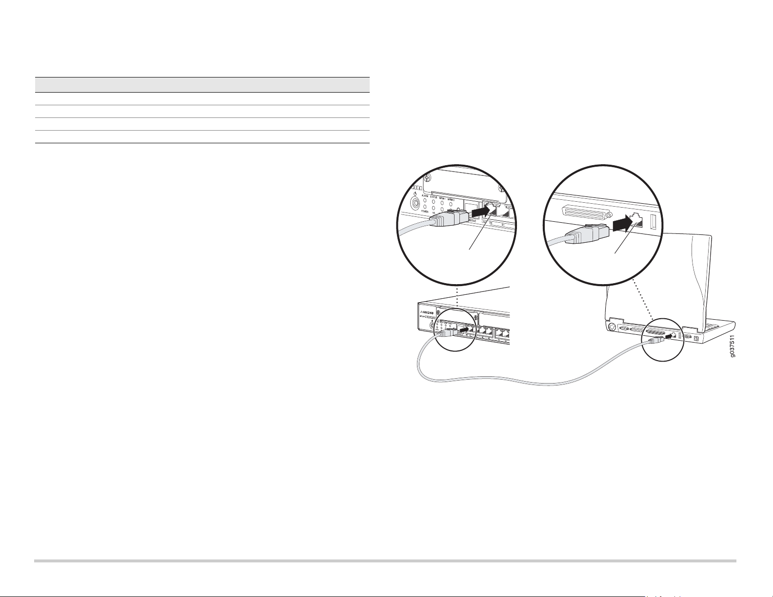
Partie 3 : Connexion du dispositif de gestion
Connectez le dispositif de gestion à la passerelle de services de l’une des manières
suivantes :
À l’aide d’un câble RJ-45 (câble Ethernet), reliez l’un des ports ge-0/0/1 à ge-0/0/15
du panneau avant de l’unité au port Ethernet du dispositif de gestion (poste de
travail ou ordinateur portable).
Cette méthode est recommandée. Si vous optez pour cette méthode de connexion,
passez à la Partie 4.
À l’aide d’un câble RJ-45 (câble Ethernet), reliez le port Console de l’unité à
l’adaptateur DB-9 fourni, puis connectez ce dernier au port série du dispositif de
gestion. (Paramètres du port série : 9600 8-N-1.)
Si vous optez pour cette méthode de connexion, reportez-vous aux instructions de
configuration de l’interface de ligne de commande indiquées dans le guide Branch
SRX Series Services Gateways Golden Configurations disponible à l’adresse
http://www.juniper.net/us/en/local/pdf/app-notes/3500153-en.pdf.
Pour plus d’informations sur la connexion d’une interface de gestion, observez
l’illustration ci-après :
Partie 4 : Présentation des paramètres de configuration par défaut
La passerelle de services J-SRX240 est un dispositif de routage sécurisé dont le bon
fonctionnement est tributaire des paramètres de configuration de base suivants :
Vous devez attribuer des adresses IP aux interfaces.
Vous devez associer les interfaces à des zones.
Vous devez configurer des règles autorisant ou refusant la transmission de données
entre les zones.
Vous devez définir les règles NAT des adresses source.
Lorsque vous mettez l’unité sous tension pour la première fois, elle utilise la
configuration par défaut suivante. Pour vous en servir, aucune configuration initiale n’est
nécessaire.
Unité Mémoire DDR Alimentation via
Ethernet
Prise en charge
de la voix
J-SRX240B 512 Mo Non Non
J-SRX240H 1 Go Non Non
J-SRX240H-POE 1 Go Oui Non
J-SRX240H-P-MGW 1 Go Oui Oui
Port Ethernet
Port Ethernet
Câble RJ-45
Page 3
PARAMèTRES PAR DéFAUT DéFINIS EN USINE DES INTERFACES
PARAMèTRES PAR DéFAUT DéFINIS EN USINE DES RèGLES DE SéCURITé
PARAMèTRES PAR DéFAUT DéFINIS EN USINE DE LA RèGLE NAT
Partie 5 : Vérification de l’attribution d’une adresse IP au dispositif de
gestion
Une fois le dispositif de gestion connecté à la passerelle de services, le processus du
serveur DHCP sur cette passerelle attribue automatiquement une adresse IP à ce
dispositif. Assurez-vous que le dispositif de gestion reçoit bien de l’unité une adresse IP
sur le sous-réseau 192.168.1/24 (autre que 192.168.1.1).
REMARQUE :
La passerelle de services se comporte comme un serveur DHCP et attribue une
adresse IP au dispositif de gestion.
Si aucune adresse IP n’est attribuée au dispositif de gestion, configurez-en une
manuellement sur le sous-réseau 192.168.1.0/24. N’attribuez pas l’adresse IP
192.168.1.1 au dispositif de gestion ; elle est déjà attribuée à l’unité. Par défaut, le
serveur DHCP est activé sur l’interface de VLAN de couche 3, à savoir (IRB) vlan.0
(de ge-0/0/1 à ge-0/0/15), dotée de l’adresse IP 192.168.1.1/24.
Lorsque vous mettez la passerelle de services J-SRX240 sous tension pour la
première fois, elle démarre en utilisant sa configuration par défaut définie en usine.
Partie 6 : Vérification de l’attribution d’une adresse IP à la passerelle de
services
Pour obtenir une adresse IP sur la passerelle de services, procédez de l’une des
manières suivantes :
MéTHODE 1: OBTENTION D’UNE ADRESSE IP DYNAMIQUE SUR LA PASSERELLE DE
SERVICES
Connectez-vous à votre fournisseur d’accès Internet (FAI) via le port ge-0/0/0.
Votre FAI va utiliser le processus DHCP pour attribuer une adresse IP à l’unité.
Si vous optez pour cette méthode d’obtention de l’adresse IP sur la passerelle,
passez aux instructions des Parties 7 à 10 du présent document pour configurer
l’unité et la transmission de données.
Mé
THODE 2: OBTENTION D’UNE ADRESSE IP STATIQUE SUR LA PASSERELLE DE
SERVICES
Connectez-vous à votre FAI via le port ge-0/0/0. Votre FAI vous communique une
adresse IP statique. Il n’utilisera pas le processus DHCP pour vous attribuer une
adresse IP.
Si vous optez pour cette méthode d’obtention de l’adresse IP sur la passerelle,
passez aux instructions des Parties 7 à 10 du présent document.
Partie 7 : Accès à l’interface J-Web
1. Lancez un navigateur Web sur le dispositif de gestion.
2. Saisissez http://192.168.1.1 dans le champ d’adresse URL. La page de connexion
à l’interface J-Web s’affiche.
3. Indiquez le nom d’utilisateur par défaut root. N’entrez aucun mot de passe dans le
champ Password.
4. Cliquez sur Log In. La page Initial Setup de l’interface J-Web apparaît.
Partie 8 : Configuration des paramètres de base
Configurez les paramètres de base, tels que Host Name, Domain Name et Root
Password, de la passerelle de services.
IMPORTANT:
avant d’appliquer votre configuration, vérifiez que vous avez configuré
l’adresse IP et le mot de passe de l’utilisateur root.
REMARQUE :
chaque champ signalé par un astérisque (*) est obligatoire.
Si, à la Partie 6, vous avez opté pour la Méthode 2 pour obtenir une adresse IP sur la
passerelle de services, n’oubliez pas de modifier les paramètres J-Web comme suit :
1. Décochez la case Enable DHCP on ge-0/0/0.0.
2. Saisissez l’adresse IP manuelle fournie par votre FAI dans le champ
d’adresse ge-0/0/0.0. Cette adresse IP doit respecter le format
a.b.c.d/xx
,
xx
étant le
masque de sous-réseau.
3. Saisissez l’adresse IP de la passerelle dans le champ Default Gateway. Vous
obtiendrez également cette adresse IP auprès de votre FAI.
Port Label Interface Security Zone DHCP State IP Address
0/0 ge-0/0/0 untrust client non attribuée
de 0/1 à 0/15 de ge-0/0/1
à ge-0/0/15
trust server 192.168.1.1/24
Source Zone Destination Zone Policy Action
trust untrust autoriser
trust trust autoriser
untrust trust interdire
Source Zone Destination Zone Policy Action
trust untrust définir l’adresse NAT source sur
l’interface de la zone Untrust
 Loading...