


PowerEdge Rack Enclosure 2410 Cabling R510
Table of contents
 Loading...
Dell PowerEdge Rack Enclosure 2410 Cabling R510, PowerEdge Rack Enclosure 4620S Cabling R510 White Paper

Cable Routing Procedures
for Dell™ PowerEdge™
R510 Systems
A Dell Technical White Paper
Dell │ Datacenter Infrastructure Engineering
By Riyad Moe and Jose L. Flores
November 2009

Cable Routing Procedures for Dell™ PowerEdge™ R510 Systems
Page ii
THIS WHITE PAPER IS FOR INFORMATIONAL PURPOSES ONLY, AND MAY CONTAIN TYPOGRAPHICAL ERRORS AND
TECHNICAL INACCURACIES. THE CONTENT IS PROVIDED AS IS, WITHOUT EXPRESS OR IMPLIED WARRANTIES OF
ANY KIND.
© 2009 Dell Inc. All rights reserved. Reproduction of this material in any manner whatsoever without the express
written permission of Dell Inc. is strictly forbidden. For more information, contact Dell.
Dell, the DELL logo, the DELL badge, and PowerEdge are trademarks of Dell Inc.

Cable Routing Procedures for Dell™ PowerEdge™ R510 Systems
Page 1
Contents
Introduction ............................................................................................................................................................... 2
Section 1: Cabling a Dell™ PowerEdge™ R510 With a Cable Management Arm (CMA) ............................................ 2
1.1 Connecting the CMA Cables to the System .................................................................................................. 2
1.2 Installing the Inner CMA Attachment Bracket ................................................................................................. 3
1.3 Routing the Power Cables Through the Strain Reliefs ..................................................................................... 3
1.4 Routing the Cables Through the CMA ............................................................................................................. 3
1.5 Left-Side Mounting Instructions ...................................................................................................................... 4
1.6 Right-Side Mounting Instructions .................................................................................................................... 5
Section 2: Cabling a Dell™ PowerEdge™ R510 System Without a CMA .................................................................... 6
2.1 Routing the Cables ........................................................................................................................................... 6
2.2 Removing the CMA Brackets for Shallow Racks .............................................................................................. 7
Section 3: Replacing a Power Supply on a PowerEdge™ R510 System With a CMA ................................................. 8
3.1 Replacing a Power Supply with a Left-Side Mounted CMA ............................................................................. 8
3.2 Replacing a Power Supply with a Right-Side Mounted CMA ........................................................................... 8
Section 4: Cabling a PowerEdge™ R510 System Installed in Static Rails ................................................................... 9
Table of Figures
Figure 1: System with Cables Installed .......................................................................................................................... 2
Figure 2: Attaching the Inner CMA Attachment Bracket ............................................................................................... 3
Figure 3: Routing Power Cables Through the Strain Reliefs .......................................................................................... 3
Figure 4: Routing the Cables Through the CMA ............................................................................................................ 4
Figure 5: Left-Side Mounted CMA Installation .............................................................................................................. 5
Figure 6: Right-Side Mounted CMA Installation ............................................................................................................ 6
Figure 7: Cable Routing Without a CMA ........................................................................................................................ 7
Figure 8: Removing the CMA Brackets for Shallow Racks ............................................................................................. 7
Figure 9: Disconnecting the Inner CMA Attachment Bracket ........................................................................................ 8
Figure 10: Replacing the Power Supply ......................................................................................................................... 9
Figure 11: Cabling a System Installed in Static Rails ...................................................................................................... 9
Cable Routing Procedures for Dell™ PowerEdge™ R510 Systems
Page 2
Introduction
This white paper covers recommended cable routing procedures for Dell™ PowerEdge™ R510 systems in the
following racks:
• PowerEdge™ 4210
• PowerEdge™ 2410
• PowerEdge™ 4220
• PowerEdge™ 2420
If you are using the optional CMA, following these procedures will allow you to extend the system from the rack
for service without powering down or disconnecting the cables. If you are not using the CMA, following these
procedures will ensure secure attachment and strain relief of the cables behind the system. For guidelines on how
to route cables within the rack, refer to the Dell Best Practices Guide for Rack Enclosure white paper.
Section 1: Cabling a Dell™ PowerEdge™ R510 With a Cable Management Arm (CMA)
This section details how to cable a PowerEdge™ R510 system using a CMA. If you are cabling the
system without the optional CMA, refer to Section 2.
Follow the instructions contained in the Rack Installation Guide in the rail kit to install the server into the
rack. Once installed, use these instructions to install the cables. All illustrations in the following sections
were created using a PowerEdge™ R510 system.
NOTE: PowerEdge™ R510 systems are not compatible with previous generation rails and CMAs.
1.1 Connecting the CMA Cables to the System
Attach the CMA tray to the back of the rails as described in the CMA Installation Instructions provided in
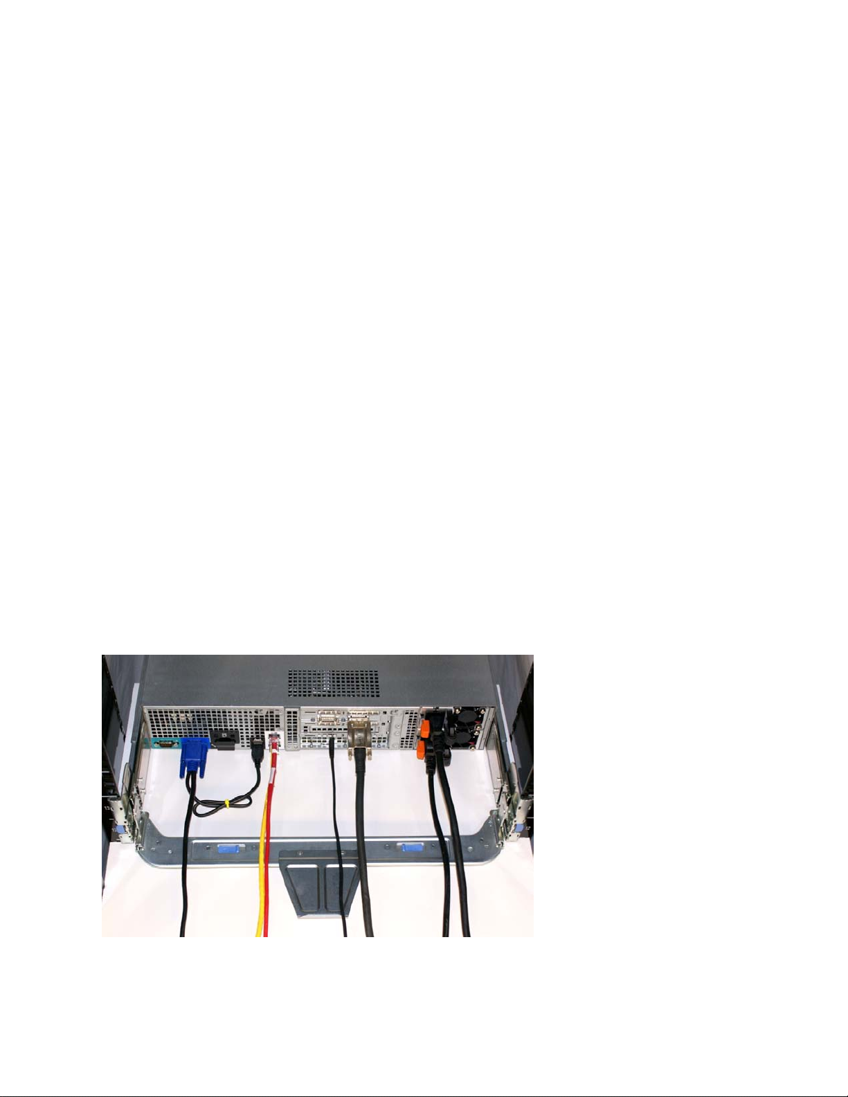
the CMA kit. Connect all applicable cables to the rear of the system and verify that all connections are
secure. See Figure 1.
Figure 1: System with Cables Installed
Loading...