


 Loading...
Dell™ PowerConnect™
6024/6024F Systems
Getting Started Guide
Začínáme
Guide de mise en route
Handbuch zum Einstieg
Οδηγός έναρξης
Instrukcja uruchomienia
Guía de introducción
הדובע תליחת ךירדמ
Models: 6024 and 6024F
w w w . d e l l . c o m | s u p p o r t . d e l l . c o m
Dell™ PowerConnect™
6024/6024F Systems
Getting Started Guide
w w w . d e l l . c o m | s u p p o r t . d e l l . c o m

Notes, Notices, and Cautions
NOTE: A NOTE indicates important information that helps you make better use of your computer.
NOTICE: A NOTICE indicates either potential damage to hardware or loss of data and tells you how to avoid the problem.
 CAUTION: A CAUTION indicates a potential for property damage, personal injury, or death.
Information in this document is subject to change without notice. © 2004-2005 Dell Inc. All rights reserved.
Reproduction in any manner whatsoever without the written permission of Dell Inc. is strictly forbidden.
Trademarks used in this text: Dell, the DELL logo, and PowerConnect are trademarks of Dell Inc.; Microsoft and Windows are registered trademarks of Microsoft Corporation.
Other trademarks and trade names may be used in this document to refer to either the entities claiming the marks and names or their products. Dell Inc. disclaims any proprietary interest in trademarks and trade names other than its own.
Models 6024 and 6024F
January 2005 |
P/N N5382 |
Rev. A01 |
Installation
Overview
This document provides basic information to install, configure, and operate
Dell™ PowerConnect™ 6024 and 6024F systems. For more information, see the User's Guide, which is available on your User Documentation CD, or check the Dell Support website at support.dell.com for the latest updates on documentation and software.
Site Preparation
PowerConnect 60xx devices can be mounted in a standard 48.26-cm (19-inch) rack or left free-standing (placed on a tabletop). Before installing the device, ensure that the chosen installation location meets the following site requirements:
•Power — The device is installed near an easily accessible 100–250 VAC, 50–60 Hz outlet.
•General — The power supply is correctly installed by checking that the LEDs on the front panel are illuminated.
•Clearance — There is adequate frontal clearance for operator access. Allow clearance for cabling, power connections, and ventilation.
•Cabling — The cabling is routed to avoid sources of electrical noise such as radio transmitters, broadcast amplifiers, power lines, and fluorescent lighting fixtures.
•Ambient — The ambient device operating temperature range is 0 to 55ºC (32 to 131ºF) at a relative humidity of up to 95 percent, non-condensing.
Unpacking
Package Contents
When unpacking the device, ensure that the following items are included:
•One PowerConnect device
•Two AC power cables
•One RS-232 crossover cable
•One rack-mount kit for rack installation (two mounting brackets, bolts, and cage nuts)
•One set of self-adhesive rubber pads for the free-standing device (four pads are included)
•User Documentation CD
•Getting Started Guide
•Safety and Regulatory Information document
Getting Started Guide |
3 |

w w w . d e l l . c o m | s u p p o r t . d e l l . c o m
Unpacking the Device
NOTE: Before unpacking the device, inspect the container and immediately report any evidence of damage.
1Place the container on a clean, flat surface and cut all straps securing the container.
2Open the container or remove the container top.
3Carefully remove the device from the container and place it on a secure and clean surface.
4Remove all packing material.
5Inspect the product and accessories for damage. Report any damage immediately.
Mounting the Device
The following instructions apply to PowerConnect 60xx series devices. The PowerConnect 6024 and 6024F have the console port on the front panel.
The power connectors are positioned on the back panel of the device. We recommend connecting both hot-swappable power supplies.
Installing in a Rack
CAUTION: Do not use rack mounting kits to suspend the device from under a table or desk, or attach it to a wall.
CAUTION: Disconnect all cables from the device before continuing. Remove all self-adhesive pads from the underside of the device, if they have been attached.
CAUTION: When mounting multiple devices into a rack, mount the devices from the bottom up.
4 Getting Started Guide
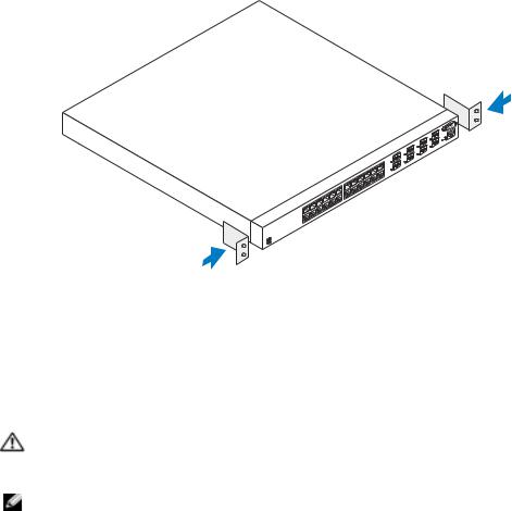
1Place the supplied rack-mounting bracket on one side of the device, ensuring that the mounting holes on the device line up to the mounting holes on the rack-mounting bracket. Figure 1-1 illustrates where to mount the brackets.
Figure 1-1. Attaching the Brackets
2Insert the supplied bolts into the rack-mounting holes and tighten with a screwdriver.
3Repeat the process for the rack-mounting bracket on the other side of the device.
4Insert the device into the 48.26 cm (19 inch) rack, ensuring that the rack-mounting holes on the device line up to the mounting holes on the rack.
5Secure the device to the rack with either the rack bolts or cage nuts and cage nut bolts with washers (depending on the kind of rack you have). Fasten the bolts on bottom before fastening the bolts on top. Ensure that the ventilation holes are not obstructed.
CAUTION: Ensure that the supplied rack bolts fit the pre-threaded holes on the rack.
Installing on a Flat Surface (Free-standing Device)
NOTE: We highly recommend that the device be mounted.
Install the device on a flat surface if you are not installing it on a rack. The surface must be able to support the weight of the device and the device cables. The device is supplied with four self-adhesive rubber pads.
1Attach the self-adhesive rubber pads on each location marked on the bottom of the chassis.
2Set the device on a flat surface, leaving 5.08 cm (2 inches) on each side and 12.7 cm (5 inches) at the back.
3Ensure that the device has proper ventilation.
Getting Started Guide |
5 |

w w w . d e l l . c o m | s u p p o r t . d e l l . c o m
Connecting a Device to a Power Supply
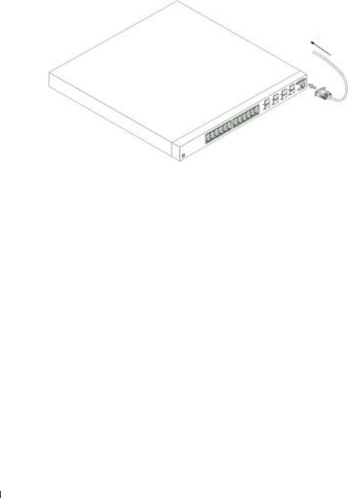
Connect the supplied AC power cable to the AC power connector located on the back panel.
NOTE: Do not connect the power cable to a grounded AC outlet at this time. Connect the device to a power source as described in the step detailed in “Starting and Configuring the Device."
NOTE: Read the safety information in the Product information Guide as well as the safety information for other devices that connect to or support the switch.
Figure 1-2. Connecting Power Cable
6 Getting Started Guide

Starting and Configuring the Device
After completing all external connections, connect a terminal to the device to configure the device. Additional advanced functions are described in the User's Guide located on your
User Documentation CD.
NOTE: Read the release notes for this product before proceeding. You can download the release notes from the Dell Support website at support.dell.com.
NOTE: We recommend that you obtain the most recent version of the user documentation from the Dell Support website at support.dell.com.
Connecting the Terminal to the Device
A console port on the device enables you to connect the device to a terminal desktop system running terminal emulation software; for monitoring and configuring the device. The console port connector is a male DB-9 connector, implemented as a data terminal equipment (DTE) connector.
To use the console port, the following is required:
•VT100-compatible terminal or a desktop or a portable system with a serial port, running VT100 terminal emulation software.
•An RS-232 crossover cable with a female DB-9 connector for the console port and the appropriate connector for the terminal.
Perform the following tasks to connect a terminal to the device console port:
1Connect an RS-232 crossover cable to the terminal running VT100 terminal emulation software.
2Configure the terminal emulation software as follows:
a Select the appropriate serial port (serial port 1 or serial port 2) to connect to the console. b Set the data rate to 115200 baud.
c Set the data format to 8 data bits, 1 stop bit, and no parity. d Set the flow control to none.
e Select VT100 for Emulation mode under Properties.
f Select Terminal keys for Function, Arrow, and Ctrl keys. Ensure that the setting is for Terminal keys (not Microsoft® Windows® keys).
NOTICE: When using HyperTerminal with Microsoft Windows 2000, ensure that you have Windows 2000 Service Pack 2 or later installed. With Windows 2000 Service Pack 2, the arrow keys function properly in HyperTerminal's VT100 emulation. Go to www.microsoft.com for more information on Windows 2000 service packs.
3Connect the female connector of the RS-232 crossover cable directly to the device console port, and tighten the captive retaining bolts. The PowerConnect 6024 and 6024F console ports are located on the front panel as shown in Figure 1-3.
Getting Started Guide |
7 |

w w w . d e l l . c o m | s u p p o r t . d e l l . c o m
Figure 1-3. Connecting to the Console Port
to VT100 terminal device
to console port
Booting the Device
1Ensure that the device console port is connected to a VT100 terminal device or VT100 terminal emulator via the RS-232 crossover cable.
2Locate an AC power receptacle.
3Deactivate the AC power receptacle.
4Connect the device to the AC receptacle.
5Activate the AC power receptacle.
When the power is turned on with the local terminal already connected, the device goes through a power-on self-test (POST). POST runs every time the device is initialized and checks hardware components to determine if the device is fully operational before completely booting. If POST detects a critical problem , the program flow stops. If POST passes successfully, a valid executable image is loaded into RAM. POST messages are displayed on the terminal and indicate test success or failure. The boot process runs for approximately 30 seconds.
Initial Configuration
NOTE: The initial simple configuration procedure is based on the following assumptions:
•The PowerConnect device was never configured before and is in the same state as when you received it.
•The PowerConnect device booted successfully.
•The console connection was established and the console prompt appears on the screen of a VT100 terminal device.
8 Getting Started Guide
The initial device configuration is performed through the console port. After the initial configuration, you can manage the device either from the already-connected console port or remotely through an interface defined during the initial configuration.
NOTE: The device is not configured with a default user name and password.
NOTE: All of the above settings are necessary to allow the remote management of the device through Telnet (Telnet client) or HTTP (Web browser).
Before setting up the initial configuration of the device, obtain the following information from your network administrator:
•The IP address to be assigned to the Out-of-Band Ethernet Management Port through which the device is managed.
•The IP subnet mask for the network
•The IP address of the Out-of-Band Ethernet Management Port default gateway for configuring the default route.
NOTE: For additional information about the Out-of-Band Ethernet Management Port see the User’s Guide.
Initial Configuration Procedure
You can perform the initial configuration using the Dell PowerConnect Easy Setup Wizard, or by using the Command Line Interface (CLI). The Setup Wizard automatically starts when the device configuration file is empty. You can invoke CLI by entering [ctrl+z] anytime during the wizard.
For more information on CLI initial configuration see the User Guide. This guide shows how to use the Setup Wizard for initial device configuration. The Setup Wizard configures the following fields.
•SNMP Community String and SNMP Management System IP address (optional)
•Username and Password
•Out-of-Band Ethernet Management Port IP Address
•Out-of-Band Ethernet Management Port default gateway address
After the device completes the POST and is booted, the following information appears:
Welcome to Dell Easy Setup Wizard
The Setup Wizard guides you through the initial switch configuration, and gets you up and running easily and quickly. You can also skip the setup wizard, and enter CLI mode to manually configure the switch if you prefer.
You can exit the Setup Wizard at any time by entering [ctrl+Z].
The system will prompt you with a default answer; by pressing enter, you accept the default.
After you configure basic settings using the Setup Wizard, you can manage the device from the Out-of-band ethernet management port.
Would you like to enter the setup wizard? (Y/N)[Y]
Getting Started Guide |
9 |

w w w . d e l l . c o m | s u p p o r t . d e l l . c o m
1If you enter [N], the Setup Wizard exits. If there is no response within 60 seconds, the Setup Wizard automatically exits and the CLI console prompt appears. If you enter [Y], the Setup Wizard provides interactive guidance throughout the initial device configuration.
NOTE: If there is no response within 60 seconds, and there is a BootP server on the network, an address is retrieved from the BootP server.
NOTE: You can exit the Setup Wizard at any time by entering [ctrl+z].
Wizard Step 1
If you enter [Y] the following information appears:
The system is not setup for SNMP management by default. To manage the switch using SNMP (required for Dell Network Manager) you can:
•Setup the initial SNMP version 2 account now.
•Return later and setup the SNMP version 2 account. (For more information on setting up a SNMP version 2 account, see the user documentation).
Would you like to setup the SNMP management interface now? (Y/N)[Y]
1Enter [N] to skip to Step 2 or enter [Y] to continue the Setup Wizard. If you enter [Y] the following information appears:
To setup the SNMP management account you must specify the management system IP address and the “community string” or password that the particular management system uses to access the switch. The wizard automatically assigns the highest access level [Privilege Level 15] to this account. You can use Dell Network Manager or other management interfaces to change this setting later, and to add additional management system later. For more information on adding management systems, see the user documentation.
To add a management station:
Please enter the SNMP community string to be used:[Dell_NetWork_Manager]
2Enter the following: User SNMP community string, for example "MYSETUPWIZARD".
3Press Enter.
10 Getting Started Guide

Wizard Step 2
Please enter the IP address of the Management System (A.B.C.D) or wildcard (0.0.0.0) to manage from any Management Station:[0.0.0.0]
1Enter
– Management System IP address for example “0.0.0.0”, or wildcard mask.
2Press Enter.
Wizard Step 3
The following information appears:
Now we need to setup your initial privilege (Level 15) user account. This account is used to login to the CLI and Web interface. You may setup other accounts and change privilege levels later. For more information on setting up user accounts and changing privilege levels, see the user documentation.
To setup a user account:
Please enter the user name:
Please enter the user password:
Please reenter the user password:
1Enter:
–User name, for example “admin”
–Password and password confirmation.
NOTE: If the first and second password entries are not identical, the wizard prompts you to enter identical passwords.
2Press Enter.
3Enter the password, for example "secret".
4Press enter.
5Confirm the password, by entering the identical string, for example, "secret".
6Press Enter.
Getting Started Guide |
11 |

w w w . d e l l . c o m | s u p p o r t . d e l l . c o m
Wizard Step 4
The following information appears:
Next, an IP address is setup. The IP address is defined on the OOB port. This is the IP address you use to access the CLI, Web interface, or SNMP interface for the switch.
To setup an IP address:
Please enter the IP address of the device (A.B.C.D):
Please enter the IP subnet mask (A.B.C.D or /nn):
1Enter the IP address, for example 192.168.1.100.
2Press Enter.
3Enter the IP subnet mask, for example 255.255.255.0
4Press Enter.
Wizard Step 5
The following information appears:
Finally, setup the default gateway. Please enter the IP address of the gateway from which this network is reachable
(for example 192.168.1.1):
1Enter the default gateway, for example, 192.168.1.1.
2Press Enter.
The following information appears (as per the example parameters described):
This is the configuration information that has been collected: SNMP Interface = MYSETUPWIZARD@0.0.0.0
User Account setup = admin Password = **********
Management IP address = 192.168.1.100 255.255.255.0 Default Gateway = 192.168.1.1
12 Getting Started Guide
Wizard Step 6
The following information appears:
If the information is correct, please select (Y) to save the configuration, and copy to the start-up configuration file. If the information is incorrect, select (N) to discard configuration and restart the wizard: [Y/N]
1Enter [Y] to complete the Setup Wizard or enter [N] to skip to restart the wizard. If you enter [Y] the following information appears:
Configuring SNMP management interface. Configuring user account.......
Configuring IP and subnet......
...............................
Thank you for using Dell Easy Setup Wizard. You will now enter CLI mode.
Wizard Step 7
The CLI prompt appears.
You can now manage the device from the already connected Console port or remotely through the Out-of-Band Ethernet Management Port interface defined during the initial configuration.
Getting Started Guide |
13 |

w w w . d e l l . c o m | s u p p o r t . d e l l . c o m
Guide Started Getting 14
Dell™ PowerConnect™
6024/6024F
w w w . d e l l . c o m | s u p p o r t . d e l l . c o m
 :
:
 :
:
 :
:
____________________
© 2004-2005 Dell Inc.
Dell Inc.
Dell DELL PowerConnect Dell Inc. Microsoft Windows Microsoft Corporation
Dell Inc.
6024 6024F
2005 1 |
P/N N5382 A01 |

Dell™ PowerConnect™ 6024 6024FDell Web support.dell.com
PowerConnect 60xx 48.26 19
•— 100-250 50-60
•— LED
•—
•—
•— 0 55 32 131 95%
•PowerConnect
•RS-232
17

w w w . d e l l . c o m | s u p p o r t . d e l l . c o m
 :
:
PowerConnect 60xx PowerConnect 6024 6024F
 :
:
 :
:
 :
:
18

1 定孔对齐。图1-1
1-1.
448.26 19
 :
:
 :
:
备电缆的重量。
25.08 (2 ) 12.7 (5 )
19

w w w . d e l l . c o m | s u p p o r t . d e l l . c o m
 : “ ”
: “ ”
 :
:
1-2.
20

盘上的
 : Dell Web support.dell.com
 : Dell Web support.dell.com
和配置设备。控制台端口连接器是一个作为数据终端设备(DTE) DB-9
•VT100 VT100
•DB-9 RS-232
1RS-232 VT100
a 1 2 b 115200
c 8 1 d none
e Properties VT100 for Emulation VT100
fCtrl Microsoft® Windows®
: Microsoft Windows 2000 HyperTerminal Windows 2000 2Windows 2000 2 HyperTerminal VT100Windows 2000 www.microsoft.com
3RS-232
PowerConnect 6024 6024F 1-3
21
w w w . d e l l . c o m | s u p p o r t . d e l l . c o m
1-3.
VT100
1RS-232 VT100 VT100
(POST)(RAM)30
 :
:
•PowerConnect
•PowerConnect
•VT100
 :
:
22

 : HTTP Web
•“ ” IP
•IP
•“ ” IP
 : “ ”
: “ ”
“Dell PowerConnect ” “ ” (CLI)“ ”[ctrl+z] CLI CLI“ ” “ ”
•SNMP SNMP IP
•IP
Welcome to Dell Easy Setup Wizard
The Setup Wizard guides you through the initial switch configuration, and gets you up and running easily and quickly. You can also skip the setup wizard, and enter CLI mode to manually configure the switch if you prefer.
You can exit the Setup Wizard at any time by entering [ctrl+Z].
The system will prompt you with a default answer; by pressing enter, you accept the default.
After you configure basic settings using the Setup Wizard, you can manage the device from the Out-of-band ethernet management port.
Would you like to enter the setup wizard? (Y/N)[Y]
“Dell ”
“ ” CLI
[ctrl+Z] “ ”Enter
“ ”
(Y/N)[Y]
23

w w w . d e l l . c o m | s u p p o r t . d e l l . c o m
1[N]“ ” 60 “ ”CLI [Y]“ ”
 : 60 BootP BootP
 : [ctrl+Z] “ ”
1
[Y]
The system is not setup for SNMP management by default. To manage the switch using SNMP (required for Dell Network Manager) you can:
•Setup the initial SNMP version 2 account now.
•Return later and setup the SNMP version 2 account. (For more information on setting up a SNMP version 2 account, see the user documentation).
Would you like to setup the SNMP management interface now? (Y/N)[Y]
SNMP SNMP “Dell”
•SNMP 2
•SNMP 2 SNMP 2
SNMP (Y/N)[Y]
1[N] 2 [Y] “ ” [Y]
To setup the SNMP management account you must specify the management system IP address and the “community string” or password that the particular management system uses to access the switch. The wizard automatically assigns the highest access level [Privilege Level 15] to this account. You can use Dell Network Manager or other management interfaces to change this setting later, and to add additional management system later. For more information on adding management systems, see the user documentation.
24

To add a management station:
Please enter the SNMP community string to be used:[Dell_NetWork_Manager]
SNMP IP “ ”[ 15] “Dell ”
SNMP [Dell_NetWork_Manager]
2SNMP “MYSETUPWIZARD”
3Enter
2
Please enter the IP address of the Management System (A.B.C.D) or wildcard (0.0.0.0) to manage from any Management Station:[0.0.0.0]
“ ” IP (A.B.C.D) (0.0.0.0) “” [0.0.0.0]
– “ ” IP “0.0.0.0”
2Enter
3
Now we need to setup your initial privilege (Level 15) user account. This account is used to login to the CLI and Web interface. You may setup other accounts and change privilege levels later. For more information on setting up user accounts and changing privilege levels, see the user documentation.
To setup a user account:
Please enter the user name:
Please enter the user password:
Please reenter the user password:
[ 15 ] CLIWeb
25

w w w . d e l l . c o m | s u p p o r t . d e l l . c o m
–“admin”
 :
:
2Enter
3“secret”
4Enter
5“secret”
6Enter
4
Next, an IP address is setup. The IP address is defined on the OOB port. This is the IP address you use to access the CLI, Web interface, or SNMP interface for the switch.
To setup an IP address:
Please enter the IP address of the device (A.B.C.D):
Please enter the IP subnet mask A.B.C.D or /nn):
IP IP OOB CLI
Web SNMP IP
IP
IP [A.B.C.D]
IP [A.B.C.D /nn]
1IP 192.168.1.100
2Enter
3IP 255.255.255.0
4Enter
26

5
Finally, setup the default gateway. Please enter the IP address of the gateway from which this network is reachable
(for example 192.168.1.1):
IP [ 192.168.1.1]:
1192.168.1.1
2Enter
This is the configuration information that has been collected: SNMP Interface = MYSETUPWIZARD@0.0.0.0
User Account setup = admin Password = **********
Management IP address = 192.168.1.100 255.255.255.0 Default Gateway = 192.168.1.1
SNMP = MYSETUPWIZARD@0.0.0.0
= admin
= **********
IP = 192.168.1.100 255.255.255.0
= 192.168.1.1
6
If the information is correct, please select (Y) to save the configuration, and copy to the start-up configuration file. If the information is incorrect, select (N) to discard configuration and restart the wizard:[Y/N]
[Y][N] [Y/N]
1[Y] “ ” [N] [Y]
Configuring SNMP management interface.
27

w w w . d e l l . c o m | s u p p o r t . d e l l . c o m
Configuring user account.......
Configuring IP and subnet......
...............................
Thank you for using Dell Easy Setup Wizard. You will now enter CLI mode.
SNMP
.......
IP ......
...............................
“Dell ” CLI
7
CLI
“”
28
Loading...