


Dell™ PowerEdge™ 6600 Systems Installation and Troubleshooting Guide
Introduction
Indicators, Messages, and Codes
Finding Software Solutions
Running the System Diagnostics
Troubleshooting Your System
Installing System Options
Installing Drives
Getting Help
Jumpers and Connectors
Abbreviations and Acronyms
Notes, Notices, and Cautions
NOTE: A NOTE indicates important information that helps you make better use of your computer.
NOTICE: A NOTICE indicates either potential damage to hardware or loss of data and tells you how to avoid the problem.
CAUTION: A CAUTION indicates a potential for property damage, personal injury, or death.
Information in this document is subject to change without notice.
© 2001 Dell Computer Corporation. All rights reserved.
Reproduction in any manner whatsoever without the written permission of Dell Computer Corporation is strictly forbidden.
Trademarks used in this text: Dell, the DELL logo, PowerEdge, Dell OpenManage, Dimension, Inspiron, Dell Precision, OptiPlex, Latitude, and DellNet are trademarks of Dell Computer Corporation; MS-DOS is a registered trademark of Microsoft Corporation.
Other trademarks and trade names may be used in this document to refer to either the entities claiming the marks and names or their products. Dell Computer Corporation disclaims any proprietary interest in trademarks and trade names other than its own.
Initial release: 25 Feb 02
Back to Contents Page
Jumpers and Connectors
Dell™ PowerEdge™ 6600 Systems Installation and Troubleshooting Guide
Jumpers—A General Explanation
I/O Riser Card Jumpers and Connectors
I/O Board Connectors and Buses
Microprocessor Board Connectors
SCSI Backplane Board Connectors
Peripheral Riser Card Connectors
Disabling a Forgotten Password
This section provides specific information about the jumpers on the system board. It also provides some basic information on jumpers and switches and describes the connectors and sockets on the various boards in the system.
Jumpers—A General Explanation
Jumpers provide a convenient and reversible way of reconfiguring the circuitry on a printed circuit board. When reconfiguring the system, you may need to change jumper settings on the system board. You may also need to change jumper settings on expansion cards or drives.
Jumpers
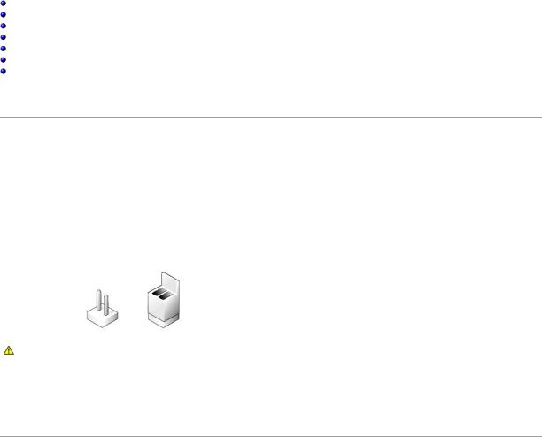
Jumpers are small blocks on a circuit board with two or more pins emerging from them. Plastic plugs containing a wire fit down over the pins. The wire connects the pins and creates a circuit. To change a jumper setting, pull the plug off its pin(s) and carefully fit it down onto the pin(s) indicated. Figure A-1 shows an example of a jumper.
Figure A-1. Example Jumpers
CAUTION: Make sure the system is turned off before you change a jumper setting. Otherwise, damage to the system or unpredictable results may occur.
A jumper is referred to as open or unjumpered when the plug is pushed down over only one pin or if there is no plug at all. When the plug is pushed down over two pins, the jumper is referred to as jumpered. The jumper setting is often shown in text as two numbers, such as 1-2. The number 1 is printed on the circuit board so that you can identify each pin number based on the location of pin 1.
Figure A-2 shows the location and default settings of the jumper blocks on the system board. See Table A-1 for the designations, default settings, and functions of the system's jumpers.
I/O Riser Card Jumpers and Connectors
Figure A-2 shows the location of the configuration jumpers and connector on the I/O riser card. Table A-1 and Table A-2 list the jumpers and connectors.
Figure A-2. I/O Riser Card Components
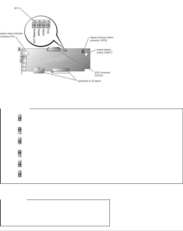
Table A-1. I/O Riser Card Jumper Settings
Jumper |
Setting |
Description |
|
|
|
NVRAM_CLR |
|
The configuration settings are retained at system boot. |
|
(default) |
|
|
|
|
|
|
The configuration settings are cleared at next system boot. (If the configuration settings become corrupted to the point where the |
|
|
system will not boot, change the jumper setting to 1–2 and boot the system. Change the jumper setting back to 2–3 before |
|
|
restoring the configuration information.) |
|
|
|
PSWD |
|
The password feature is enabled. |
|
(default) |
|
|
|
|
|
|
The password feature is disabled. |
|
|
|
RSVD |
|
Reserved (do not change). |
|
|
|
FVS |
|
Reserved (do not change). |
|
|
|
NOTE: For the full name of an abbreviation or acronym used in this table, see "Abbreviations and Acronyms."
Table A-2. I/O Riser Card Connectors
Connector or Socket |
Description |
|
|
INTR |
Chassis intrusion switch connector |
|
|
P1 |
Back-panel system status indicator |
|
|
SCSIA |
An external SCSI connector on the back panel or an internal tape drive |
|
|
VBATT |
System battery socket |
NOTE: See Figure 2-3 for back-panel connectors provided by the I/O riser card.
I/O Board Connectors and Buses
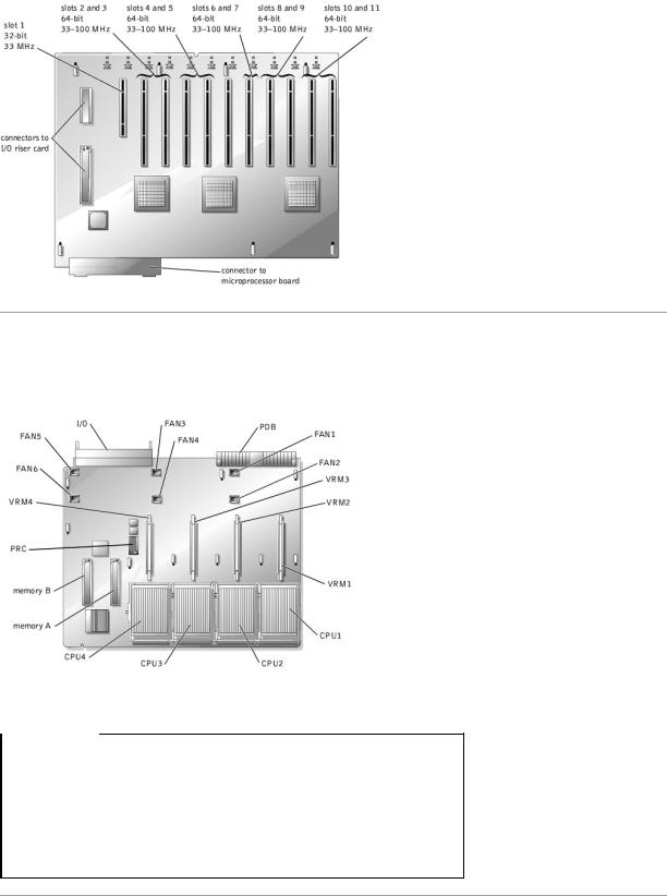
Figure A-3 shows the expansion slots, buses, and bus operating speeds.
Figure A-3. I/O Board Connectors and Buses
Microprocessor Board Connectors
See Figure A-4 and Table A-3 for the location and description of the microprocessor board connectors.
Figure A-4. Microprocessor Board Connectors
Table A-3. Microprocessor Board Connectors
Connector or Socket |
Description |
|
|
I/O |
Interface connector for the microprocessor board and the I/O board |
|
|
FANn |
Fan connectors 1 through 6 |
|
|
PDB |
Interface connector for the microprocessor board and the power distribution board |
|
|
VRMn |
VRM connectors 1 through 4 |
|
|
CPUn |
Microprocessor sockets 1 through 4 |
|
|
MEMORYn |
Memory riser card connectors A and B |
PRC |
Peripheral riser card connector |
|
|
NOTE: For the full name of an abbreviation or acronym used in this table, see "Abbreviations and Acronyms."
SCSI Backplane Board Connectors
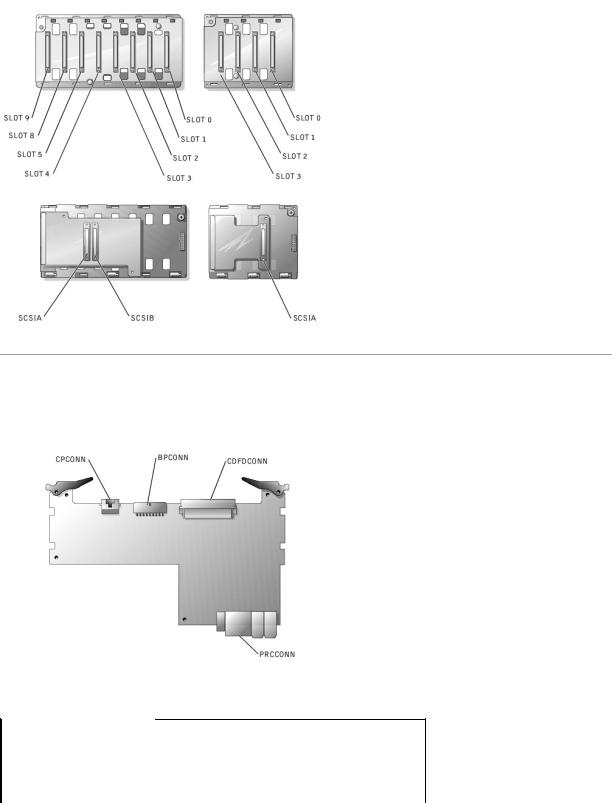
Figure A-5 shows the location of the connectors on each side of the SCSI backplane board.
Figure A-5. Connectors on the SCSI Backplane Board
Peripheral Riser Card Connectors
See Figure A-6 and Table A-4 for the location and description of the peripheral riser card connectors.
Figure A-6. Peripheral Riser Card Connectors
Table A-4. Peripheral Riser Card Connectors
Connector or Socket |
Description |
|
|
CPCONN |
Control panel cable connector |
|
|
BPCONN |
Backplane power connector (not used) |
|
|
CDFDCONN |
CD/diskette interface cable connector |
|
|
PRCCONN |
Peripheral riser card connector |
|
|
NOTE: For the full name of an abbreviation or acronym used in this table, see "Abbreviations and Acronyms."

Disabling a Forgotten Password
The system's software security features include a system password and a setup password, which are discussed in detail in "Using the System Setup Program" in the User's Guide. A password jumper on the I/O riser card enables these password features or disables them and clears any password(s) currently in use.
To disable a forgotten system password or setup password, perform the following steps.
CAUTION: See "Protecting Against Electrostatic Discharge" in the Safety Instructions in your System Information document.
1.Remove the back cover (see "Removing the Back Cover" in "Troubleshooting Your System").
2.Refer to Figure A-2 for the location of the password jumper (labeled "PSWD") on the I/O riser card.
3.Remove the jumper plug from the PSWD jumper.
4.Replace the back cover, and then reconnect the system to an electrical outlet and turn it on.
The existing passwords are not disabled (erased) until the system boots with the PSWD jumper plug removed. However, before you assign a new system and/or setup password, you must install the jumper plug.
NOTE: If you assign a new system and/or setup password with the jumper plug still removed, the system disables the new password(s) the next time it boots.
5.Repeat step 1.
6.Install the jumper plug on the PSWD jumper (see Figure A-2).
7.Replace the back cover, and then reconnect the system and peripherals to their electrical outlets and turn them on.
8.Assign a new system and/or setup password.
To assign a new passwords using the System Setup program, see "Assigning a System Password" in the User's Guide.
Back to Contents Page
Back to Contents Page
Abbreviations and Acronyms
Dell™ PowerEdge™ 6600 Systems Installation and Troubleshooting Guide
A
ampere(s)
AC
alternating current
ADC
analog-to-digital converter
ANSI
American National Standards Institute
APIC
Advanced Peripheral Interrupt Controller
ASIC
application-specific integrated circuit
BIOS
basic input/output system
BMC
baseboard management controller
bpi
bits per inch
bps
bits per second
BTU
British thermal unit
C
Celsius
CD
compact disc
CGA
color graphics adapter
cm
centimeter(s)
CMOS
complementary metal oxide semiconductor
COM
communications
cpi
characters per inch
cpl
characters per line
CPU
central processing unit
DAC
digital-to-analog converter
DAT
digital audio tape
dB
decibel(s)
dBA
adjusted decibel(s)
DC
direct current
DDR
double-data rate
DIMM
dual in-line memory module
DIN
Deutsche Industrie Norm
DIP
dual in-line package
DMA
direct memory access
DOC
Department of Communications (in Canada)
dpi
dots per inch
DRAC
Dell™ Remote Access Card
DRAM
dynamic random-access memory
DS/DD
double-sided double-density
DS/HD
double-sided high-density
ECC
error checking and correction
EDO
extended-data out
EGA
enhanced graphics adapter
EIDE
enhanced integrated drive electronics
EMI
electromagnetic interference
EMM
expanded memory manager
EMS
Expanded Memory Specification
EPP
Enhanced Parallel Port
EPROM
erasable programmable read-only memory
ESD
electrostatic discharge
ESDI
enhanced small-device interface
ESM
embedded server management
F
Fahrenheit
FAT
file allocation table
FCC
Federal Communications Commission
ft
feet
g
gram(s)
G
gravities
GB
gigabyte(s)
GUI
graphical user interface
Hz
hertz
I/O
input/output
ID
identification
IDE
integrated drive electronics
IRQ
interrupt request
K
kilo- (1024)
KB
kilobyte(s)
KB/sec
kilobyte(s) per second
Kb
kilobit(s)
Kbps
kilobit(s) per second
kg
kilogram(s)
kHz
kilohertz
LAN
local area network
lb
pound(s)
LCD
liquid crystal display
LED
light-emitting diode
LIF
low insertion force
LN
load number
lpi
lines per inch
LVD
low voltage differential
m
meter(s)
mA
milliampere(s)
mAh
milliampere-hour(s)
MB
megabyte(s)
Mb
megabit(s)
Mbps
megabit(s) per second
MBR
master boot record
MDA
monochrome display adapter
MGA
monochrome graphics adapter
MHz
megahertz
mm
millimeter(s)
ms
millisecond(s)
MTBF
mean time between failures
mV
millivolt(s)
NIC
network interface controller
NiCad
nickel cadmium
NiMH
nickel-metal hydride
NMI
nonmaskable interrupt
ns
nanosecond(s)
NTFS
NT File System
NVRAM
nonvolatile random-access memory
OTP
one-time programmable
PAL
programmable array logic
PCI
Peripheral Component Interconnect
PCMCIA
Personal Computer Memory Card International Association
PDB
power distribution board
PDU
power distribution board
PGA
pin grid array
PIC
personal identification code
POST
power-on self-test
ppm
pages per minute
PQFP
plastic quad flat pack
PSDB
power-supply distribution board
PS/2
Personal System/2
PXE
preboot execution environment
RAID
redundant arrays of independent disks
RAM
random-access memory
RCU
Resource Configuration Utility
REN
ringer equivalence number
RFI
radio frequency interference
RGB
red/green/blue
ROM
read-only memory
rpm
revolutions per minute
RTC
real-time clock
SBE
single bit ECC
SCSI
small computer system interface
sec
second(s)
SEC
single-edge contact
SEL
system event log
SDRAM
synchronous dynamic random-access memory
SIMM
single in-line memory module
SMB
server management bus
SMI
system management interrupt
SNMP
Simple Network Management Protocol
SRAM
static random-access memory
SVGA
super video graphics array
TFT
thin film transistor
tpi
tracks per inch
UMB
upper memory block
UPS
uninterruptible power supply
USB
universal serial bus
V
volt(s)
VAC
volt(s) alternating current
VDC
volt(s) direct current

VGA
video graphics array
VLSI
very-large-scale integration
VRAM
video random-access memory
VRM
voltage regulator module
W
watt(s)
WH
watt-hour(s)
XMM
extended memory manager
XMS
eXtended Memory Specification
ZIF
zero insertion force
Back to Contents Page

Back to Contents Page
Introduction
Dell™ PowerEdge™ 6600 Systems Installation and Troubleshooting Guide
Other Documents You May Need
Obtaining Technical Assistance
Your system is a high-speed server that offers significant service and upgrade features. The system includes the following service features to make troubleshooting and repair easy and effective:
•Embedded server management hardware, which monitors temperatures and voltages throughout the system and notifies you if the system overheats, if a system cooling fan malfunctions, or if a power supply fails
•Redundant, hot-pluggable cooling fans and power supplies
•System diagnostics, which checks for hardware problems (if the system can boot)
The following system upgrade options are offered:
•Additional microprocessors
•Additional memory
•A variety of PCI and PCI-X expansion-card options (including RAID controller cards)
•A remote access PCI expansion card for system management
Other Documents You May Need
Besides this Installation and Troubleshooting Guide, the following documentation is included with your system:
•The Setting Up Your System sheet provides general instructions for setting up your system.
•The System Information document provides important safety and regulatory information. Warranty information might be included within this document or as a separate document.
•The Rack Installation Guide describes how to unpack, set up, and install your system in a rack.
•The User's Guide describes system features and technical specifications, video and SCSI device drivers, the System Setup program, and software support utilities.
•The systems management software documentation describes the features, requirements, installation, and basic operation of the systems management software. See the software's online help for information about the alert messages issued by the software.
•Operating system documentation is included if you ordered the software with the system. This documentation describes how to install (if necessary), configure, and use the operating system software.
•Documentation is included with any options you purchased separately from the system. This documentation includes information that you need to configure and install these options in your system.
You may also have the following documents:
• Documentation updates are sometimes included with the system to describe changes to the system or software.
NOTE: Always read these updates before consulting any other documentation because the updates often contain information that supersedes the information in the other documents.
•Technical information files—sometimes called "readme" files—may be installed on the hard drive to provide last-minute updates about technical changes to the system or advanced technical reference material intended for experienced users or technicians.
Obtaining Technical Assistance
If at any time you do not understand a procedure described in this guide or if your system does not perform as expected, a number of tools are provided to help you. For more information on these help tools, see "Getting Help."
Back to Contents Page
Back to Contents Page
Indicators, Messages, and Codes
Dell™ PowerEdge™ 6600 Systems Installation and Troubleshooting Guide
System Status Indicators |
LCD Status Messages |
Front-Panel Indicators and Features |
System Messages |
Back-Panel Indicators and Features |
System Beep Codes |
SCSI Hard-Drive Indicator Codes |
Warning Messages |
Power-Supply Indicator Codes |
Diagnostics Messages |
NIC Indicator Codes |
Alert Messages |
Expansion-Slot Indicator Codes |
|
Applications, operating systems, and the system itself are capable of identifying problems and alerting you to them. When a problem occurs, a message may appear on the monitor or front-panel status LCD, or a beep code may sound.
Several different types of messages can indicate when the system is not functioning properly:
•System status indicators
•Front-panel indicators and features
•Back-panel indicators and features
•SCSI hard-drive indicator codes
•Power-supply indicator codes
•NIC indicator codes
•Expansion-slot indicator codes
•LCD status messages
•System messages
•System beep codes
•Warning messages
•Diagnostics messages
•Alert messages
The system indicators and features are illustrated in Figure 2-1 through Figure 2-7. This section also describes each type of message and lists the possible causes and actions you can take to resolve any problems indicated by a message. To determine what type of message you have received, read the following subsections.
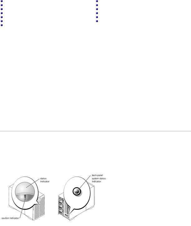
System Status Indicators
The system's bezel has an indictor that can represent system status when the bezel is installed (see Figure 2-1). The indicator identifies when the system is operating properly or when the system needs attention. The back-panel system status indicator functions the same as the bezel's status indicator. A caution code identifies a problem with power supply, system or power-supply fans, system temperature, hard drives, or expansion cards.
Table 2-1 lists the system's status indicator codes.
Figure 2-1. System Status Indicators
Table 2-1. System Status Indicator Codes
Bezel Indicators |
Back-Panel |
Indicator Code |
Status |
Caution |
Indicator |
|
|
|
||
|
|
|
|
Off |
Off |
Off |
No power is available to the system, or the system is not powered on. |
On |
Off |
Blue |
The system is operating normally. |
|
|
|
|
Off |
Blinking |
Amber blinking |
The system has detected an error and requires attention. |
|
|
|
|
Blinking |
Off |
Blue blinking |
The system is identifying itself. |
|
|
|
NOTE: Systems management software causes the status indicator to blink to identify a particular system. For more |
|
|
|
information, see the systems management software documentation. |
|
|
|
|
|
|
|
|
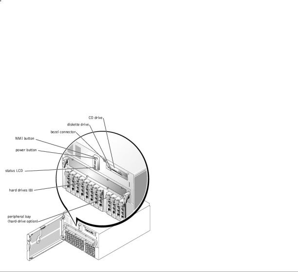
Front-Panel Indicators and Features
Additional indicators are located behind the bezel for system power and hard drives. The CD and diskette drives have green activity indicators. The front-panel LCD provides status information using an alphanumeric character display (see "LCD Status Messages"). See Figure 2-2 for the front-panel indicators and features.
Figure 2-2. Front-Panel Features
Back-Panel Indicators and Features
Figure 2-3 shows the back-panel features of the system.
Figure 2-3. Back-Panel Features

SCSI Hard-Drive Indicator Codes
Each SCSI hard-drive carrier has two indicators: a busy indicator and a status indicator (see Figure 2-4). The indicators provide information on the status of the respective hard drive. Table 2-2 lists the drive indicator codes.
Figure 2-4. SCSI Hard-Drive Indicators
Table 2-2 lists the drive indicator codes. Different codes display as drive events occur in the system. For example, in the event of a hard-drive failure, the "drive fail" code appears. After the drive is selected for removal, the "prepared for removal" code appears. After the replacement drive is installed, the "Prepare for operation, drive online" code appears.
Table 2-2. SCSI Hard-Drive Indicator Codes
Indicator |
Indicator Code |
|
|
Off |
Drive bay empty, ready for insertion or removal |
|
|
Steady green |
Drive being prepared for operation, drive online |
|
|
Blinks green four times per second |
Identify drive |
Blinks green twice per second at equal intervals |
Drive being prepared for removal |
|
|
Blinks green twice per second at unequal intervals |
Drive rebuilding |
|
|
Blinks amber four times per second |
Drive failed |
Blinks green, then amber, and then off, repeating this sequence every two seconds |
Predicted failure for the drive |
|
|
Steady green |
Drive online |
|
|
NOTE: The drive busy indicator identifies whether the hard drive is active on the SCSI bus. This indicator is controlled by the hard drive.
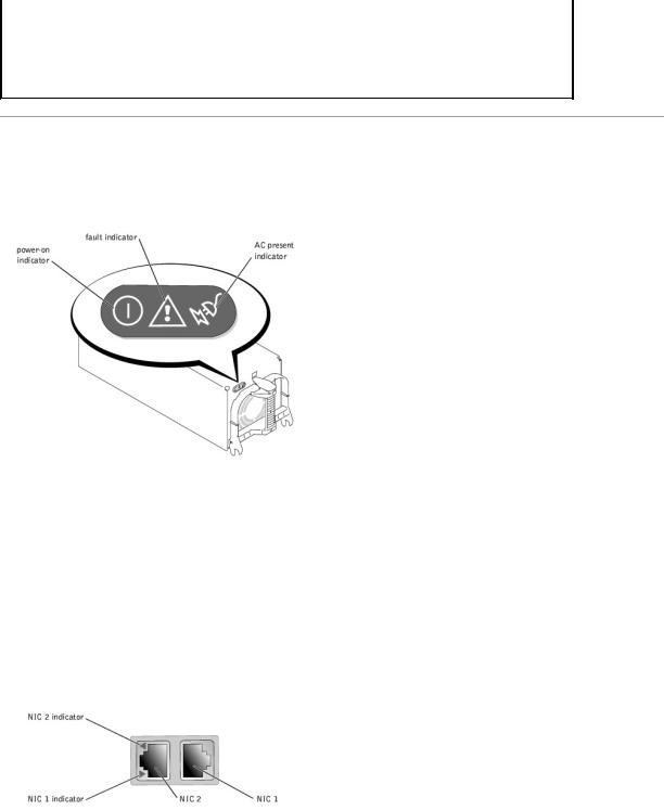
Power-Supply Indicator Codes
Each hot-pluggable power supply has three indicators that can provide information on power status, fault, and the presence of AC power (see Figure 2-5). Table 2-3 lists the power-supply indicator codes.
Figure 2-5. Power-Supply Indicators
Table 2-3. Power-Supply Indicator Codes
Indicator |
Indicator Code |
|
|
|
|
Power-on |
Green indicates that the power supply is operational. |
|
|
|
|
Fault |
Red indicates a problem with the power supply (fan failure, voltage error, etc.). |
|
|
|
|
AC present |
Green indicates that AC power is present at the power supply and that the system is connected to an AC source. |
|
|
|
|
|
|
|
NIC Indicator Codes
Each NIC has an indicator that provides information on network activity and link status (see Figure 2-6). Table 2-4 lists the NIC indicator codes.
Figure 2-6. NIC Indicators
Table 2-4. NIC Indicator Codes
Indicator |
Indicator Code |
|
|
Off |
The NIC is not connected to the network. |
|
|
Green |
The NIC is connected to a valid link partner. |
Amber blinking |
Network data is being sent or received. |
|
|
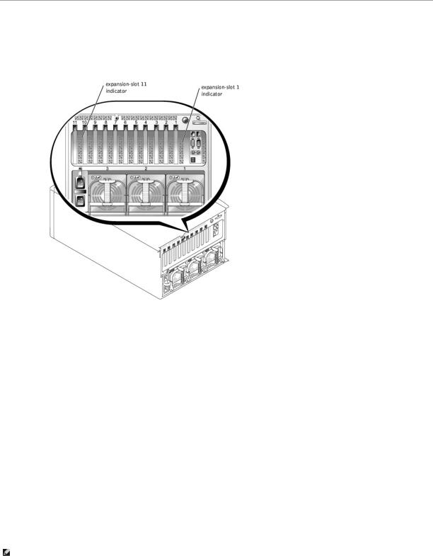
Expansion-Slot Indicator Codes
An indicator is located beside each PCI hot-pluggable expansion slot (see Figure 2-7). The indicators show through the back-panel vents. Table 2-5 lists the codes for these indicators.
Figure 2-7. Expansion-Slot Indicators
Table 2-5. Expansion-Slot Indicator Code
Indicator |
Indicator Code |
|
|
Off |
Expansion-slot power is off. No action is required. |
|
|
Green |
Expansion-slot power is on. No action is required. |
|
|
Green blinking fast |
Expansion slot is being identified by an application program or driver. No action is required. |
|
|
Amber blinking slow |
Expansion card is faulty or improperly installed, causing a problem with power supply to the card. |
Amber blinks twice, pauses, and |
Expansion card of a slower operating speed was hot-plugged. If you are replacing an expansion card with a card of a |
then repeats the sequence |
slower operating speed, you must power down the system to install the replacement card. |
|
|
|
|
LCD Status Messages
The system's bezel indictor can signify when the system is operating correctly or when the system needs attention (see Figure 2-1). When the bezel indicator signifies an error condition, open the bezel to see further information provided by the LCD.
The LCD can display two lines of alphanumeric characters. The display codes are presented in two color combinations:
•White characters on a blue background — Information only; no action is required.
•Amber characters on a black background — The system needs attention.
Table 2-6 lists the LCD status messages that can occur and the probable cause for each message. The LCD messages refer to events recorded in the system event log (SEL). For information on the SEL and configuring system management settings, see the systems management software documentation found on the documentation CD that shipped with your system.
NOTE: Before you perform any procedures described in Table 2-6, see "Before You Begin" in "Troubleshooting Your System."
Table 2-6. LCD Status Messages
Line 1 |
Line 2 |
Causes |
Corrective Actions |
Message |
Message |
|
|
SYSTEM |
SYSTEM NAME |
SYSTEM ID is a unique name, 5 characters or |
This message is for information only. |
||
ID |
|
less, defined by the user. |
|
||
|
|
|
|
You can change the system ID and name in the System Setup program. See |
|
|
|
SYSTEM NAME is a unique name, 16 characters |
your system's User's Guide. |
||
|
|
or less, defined by the user. |
|
||
|
|
The system ID and name display under the |
|
||
|
|
following conditions: |
|
||
|
|
• |
When the system is powered on |
|
|
|
|
• |
When power is off and active POST |
|
|
|
|
|
errors are displayed |
|
|
|
|
|
|
||
E0000 |
OVRFLW CHECK |
LCD overflow message. |
Check the SEL for details on the events. |
||
|
LOG |
|
|
|
|
|
|
A maximum of three error messages can |
|
||
|
|
display sequentially on the LCD. The fourth |
|
||
|
|
message displays as the standard overflow |
|
||
|
|
message. |
|
||
|
|
|
|
||
E0119 |
DRAC TEMP |
Remote access card is out of acceptable |
See "Troubleshooting System Cooling" in "Troubleshooting Your System." |
||
|
|
temperature range. |
|
||
|
|
|
|
||
E0119 |
TEMP AMBIENT |
Ambient system temperature is out of |
|
||
|
|
acceptable range. |
|
||
E0119 |
TEMP BP |
Backplane board is out of acceptable |
See "Troubleshooting System Cooling" in "Troubleshooting Your System." |
||
|
|
temperature range. |
|
||
|
|
|
|
Ensure that all power supply fans are operating properly. See "Troubleshooting |
|
|
|
|
|
Power Supplies" in "Troubleshooting Your System." |
|
E0119 |
TEMP CPU n |
Specified microprocessor is out of acceptable |
See "Troubleshooting System Cooling" in "Troubleshooting Your System." If the |
||
|
|
temperature range. |
problem persists, ensure that the specified microprocessor heat sink(s) are |
||
|
|
|
|
properly installed (see "Adding or Replacing a Microprocessor" in "Installing |
|
|
|
|
|
System Options"). |
|
|
|
|
|
||
E0119 |
TEMP MEM n |
Specified memory riser card is out of acceptable |
See "Troubleshooting System Cooling" in "Troubleshooting Your System." |
||
|
|
temperature range. |
|
||
|
|
|
|
||
E0119 |
TEMP PBAY |
Peripheral bay is out of acceptable temperature |
Ensure that all power supply fans are operating properly. See "Troubleshooting |
||
|
|
range. |
Power Supplies" in "Troubleshooting Your System." |
||
|
|
|
|
||
E0119 |
TEMP SYSTEM |
I/O riser card or I/O board is out of acceptable |
See "Troubleshooting System Cooling" in "Troubleshooting Your System." |
||
|
|
temperature range. |
|
||
E0212 |
DRAC EXT POWER |
Remote access card is out of acceptable |
See "Troubleshooting Power Supplies" in "Troubleshooting Your System." If the |
||
|
|
voltage range; faulty or improperly installed |
problem persists, ensure that the remote access card is properly installed. If |
||
E0212 |
DRAC VOLT BATT |
||||
power supply or remote access card. |
the problem persists, replace the remote access card (see "Removing an |
||||
E0212 |
DRAC VOLT PCI |
|
|
Expansion Card" in "Installing System Options"). |
|
|
|
|
|||
|
|
|
|
||
E0212 |
VOLT 3.3 |
System power supply is out of acceptable |
See "Troubleshooting Power Supplies" in "Troubleshooting Your System." |
||
|
|
voltage range; faulty or improperly installed |
|
||
E0212 |
VOLT 5 |
|
|||
power supply. |
|
||||
E0212 |
VOLT 12 |
|
|
|
|
E0212 |
VOLT BATT |
Faulty battery or I/O riser card. |
See "Troubleshooting the System Battery" and "Troubleshooting the I/O Riser |
||
|
|
|
|
Card" in "Troubleshooting Your System." |
|
|
|
|
|
||
E0212 |
VOLT BP 12 |
Backplane board is out of acceptable voltage |
Ensure that the power cables are securely connected to the backplane board |
||
|
|
range. |
(see "Installing Drives"). If the problem persists, see "Troubleshooting Power |
||
E0212 |
VOLT BP 3.3 |
||||
|
|
Supplies" in "Troubleshooting Your System." |
|||
E0212 |
VOLT BP 5 |
|
|
|
|
|
|
|
|
||
E0212 |
VOLT CPU VRM |
Microprocessor VRM voltage is out of |
Ensure that supported VRMs of the same type are properly installed. If the |
||
|
|
acceptable range; faulty or improperly installed |
problem persists, replace the VRM (see "Adding or Replacing a Microprocessor" |
||
|
|
microprocessor VRM; faulty microprocessor |
in "Installing System Options"). If the problem persists, replace the |
||
|
|
board. |
microprocessor board (see "Getting Help"). |
||
E0212 |
VOLT NIC 1.8V |
Integrated NIC voltage is out of acceptable |
See "Troubleshooting the I/O Board" and "Troubleshooting Power Supplies" in |
||
|
|
range; faulty or improperly installed I/O riser |
"Troubleshooting Your System." |
||
E0212 |
VOLT NIC 2.5V |
card; faulty or improperly installed power |
|
||
supply. |
|
||||
|
|
|
|||
|
|
|
|
||
E0212 |
VOLT MEMORY n |
Specified memory riser card is out of acceptable |
Ensure that the memory riser card is properly installed. If the problem persists, |
||
|
|
voltage range; faulty or improperly installed |
replace the memory riser card (see "Removing the Memory Riser Cards" in |
||
|
|
memory card; faulty or improperly installed |
"Installing System Options"). If the problem persists, see "Troubleshooting |
||
|
|
power supply. |
Power Supplies" in "Troubleshooting Your System." |
||
|
|
|
|
||
E0212 |
VOLT PBAY 12 |
Peripheral bay is out of acceptable voltage |
Ensure that the power cables are securely connected to the peripheral bay |
||
|
|
range. |
backplane board (see "Installing Drives"). If the problem persists, see |
||
E0212 |
VOLT PBAY 3.3 |
||||
|
|
"Troubleshooting Power Supplies" in "Troubleshooting Your System." |
|||
E0212 |
VOLT PBAY 5 |
|
|
|
|
|
|
|
|
||
E0212 |
VOLT PLANAR |
Microprocessor board is out of acceptable |
See "Troubleshooting the Microprocessor Board" in "Troubleshooting Your |
||
|
REG |
voltage range; faulty or improperly installed |
System." |
||
|
|
microprocessor board. |
|
||
E0276 |
CPU VRM n |
Specified microprocessor VRM is faulty, |
Ensure that supported VRMs of the same type are properly installed. If the |
||
|
|
unsupported, or improperly installed. |
problem persists, replace the VRM (see "Adding or Replacing a Microprocessor" |
||
|
|
||||
E0276 |
MISMATCH VRM n |
|
|
in "Installing System Options"). |
|
|
|
|
|
||
E0280 |
MISSING VRM n |
Specified microprocessor VRM is improperly |
Ensure that a supported VRM is properly installed for each microprocessor. If |
||
|
|
installed or missing. |
the problem persists, replace the VRM (see "Adding or Replacing a |
||
|
|
|
|
Microprocessor" in "Installing System Options"). |
|
|
|
|
|
||
E0319 |
PCI OVER |
Faulty or improperly installed expansion card or |
See "Troubleshooting the I/O Board" and "Troubleshooting Expansion Cards" in |
||
|
CURRENT |
I/O board. |
"Troubleshooting Your System." |
||
|
|
|
|
||
E0412 |
RPM FAN n |
Specified cooling fan is faulty, improperly |
See "Troubleshooting a Cooling Fan" in "Troubleshooting Your System." |
||
|
|
installed, or missing |
|
||
|
|
|
|
|
|
E0780 |
MISSING CPU 1 |
Microprocessor is not installed in socket 1. |
Install a microprocessor in socket 1 (see "Adding or Replacing a |
|
|
|
|
Microprocessor" in "Installing System Options"). To identify microprocessor |
|
|
|
|
socket 1, see Figure A-4. |
|
|
|
|
|
|
E07F0 |
CPU IERR |
Faulty or improperly installed microprocessor, |
See "Troubleshooting the Microprocessor Board" and "Troubleshooting the I/O |
|
|
|
microprocessor board, or I/O board. |
Board" in "Troubleshooting Your System." |
|
|
|
|
|
|
E07F1 |
TEMP CPU n HOT |
Specified microprocessor is out of acceptable |
See "Troubleshooting System Cooling" in "Troubleshooting Your System." If the |
|
|
|
temperature range and has halted operation. |
problem persists, ensure that the microprocessor heat sinks are properly |
|
|
|
|
installed (see "Adding or Replacing a Microprocessor" in "Installing System |
|
|
|
|
Options"). |
|
|
|
|
|
|
E07F4 |
POST CACHE |
Faulty or improperly installed microprocessor or |
See "Troubleshooting the Microprocessor Board" in "Troubleshooting Your |
|
|
|
microprocessor board. |
System." |
|
E07F4 |
POST CPU REG |
|||
|
|
|||
|
|
|
|
|
E07F4 |
POST CPU SMI |
SMI handler failed to initialize; faulty or |
See "Troubleshooting the I/O Riser Card," "Troubleshooting the I/O Board," |
|
|
|
improperly installed I/O riser card, I/O board, or |
and "Troubleshooting the Microprocessor Board" in "Troubleshooting Your |
|
|
|
microprocessor board. |
System." |
|
E07FA |
TEMP CPU n |
Specified microprocessor is out of acceptable |
See "Troubleshooting System Cooling" in "Troubleshooting Your System." If the |
|
|
THERM |
temperature range and is operating at a |
problem persists, ensure that the microprocessor heat sinks are properly |
|
|
|
reduced speed, or frequency. |
installed (see "Adding or Replacing a Microprocessor" in "Installing System |
|
|
|
|
Options"). |
|
E0876 |
POWER PS n |
No power is available from the specified power |
See "Troubleshooting Power Supplies" in "Troubleshooting Your System." |
|
|
|
supply; specified power supply is improperly |
|
|
|
|
installed or faulty. |
|
|
|
|
|
|
|
E0880 |
INSUFFICIENT |
Insufficient power is being supplied to the |
See "Troubleshooting Power Supplies" in "Troubleshooting Your System." |
|
|
POWER PS |
system; power supplies are improperly |
|
|
|
|
installed, faulty, or missing. |
|
|
E08F4 |
AC LINE n |
No power available through the specified |
Ensure that all power cords are securely connected. See "External |
|
|
|
power cord. |
Connections" in "Troubleshooting Your System." |
|
E0CB2 |
MEM MIRROR |
Uncorrectable memory error was remapped to |
See "Troubleshooting System Memory" in "Troubleshooting Your System." |
|
|
|
the mirrored memory bank. |
|
|
E0CB2 |
MEM SPARE ROW |
Correctable errors threshold was met in a |
|
|
|
|
memory bank, and errors are remapped to the |
|
|
|
|
spare row. |
|
|
|
|
|
|
|
E0CF1 |
MBE DIMM Bank |
Memory modules installed in the specified bank |
Ensure that all banks contain memory modules of the same type and size and |
|
|
n |
are not the same type and size; faulty memory |
that they are properly installed. If the problem persists, see "Troubleshooting |
|
|
|
module(s). |
System Memory" in "Troubleshooting Your System." |
|
E0CF1 |
POST MEM 64K |
Parity failure in the first 64 KB of main memory. |
See "Troubleshooting System Memory" in "Troubleshooting Your System." |
|
|
|
|
|
|
E0CF1 |
POST NO MEMORY |
Main-memory refresh verification failure. |
Ensure that all banks contain memory modules of the same type and size and |
|
|
|
|
that they are properly installed. If the problem persists, see "Troubleshooting |
|
|
|
|
System Memory" in "Troubleshooting Your System." |
|
E0CF5 |
LOG DISABLE |
Multiple single-bit errors on a single memory |
See "Troubleshooting System Memory" in "Troubleshooting Your System." |
|
|
SBE |
module. |
|
|
|
|
|
|
|
E0D76 |
DRIVE FAIL |
Faulty or improperly installed hard drive or RAID |
See "Troubleshooting Hard Drives" and "Troubleshooting a RAID Controller |
|
|
|
controller. |
Card" in "Troubleshooting Your System." |
|
E0F04 |
POST CMOS |
CMOS write/read failure; faulty or improperly |
See "Troubleshooting the I/O Riser Card," "Troubleshooting the I/O Board," |
|
|
|
installed I/O riser card, I/O board, or |
and "Troubleshooting the Microprocessor Board" in "Troubleshooting Your |
|
|
|
microprocessor board. |
System." |
|
|
|
|
|
|
E0F04 |
POST CPU SPEED |
Microprocessor speed control sequence failure. |
See "Troubleshooting the Microprocessor Board" in "Troubleshooting Your |
|
|
|
|
System." |
|
|
|
|
|
|
E0F04 |
POST DMA INIT |
DMA initialization failure; DMA page register |
See "Troubleshooting System Memory" and "Troubleshooting the I/O Board" in |
|
|
|
write/read failure. |
"Troubleshooting Your System." |
|
E0F04 |
POST DMA REG |
Faulty I/O board. |
See "Troubleshooting the I/O Board" in "Troubleshooting Your System." |
|
|
|
|
|
|
E0F04 |
POST KYB CNTRL |
Faulty keyboard controller; faulty I/O riser card. |
See "Troubleshooting the I/O Riser Card" in "Troubleshooting Your System." |
|
E0F04 |
POST MEM RFSH |
Main-memory refresh verification failure. |
See "Troubleshooting System Memory" in "Troubleshooting Your System." |
|
|
|
|
|
|
E0F04 |
POST PIC REG |
Master or slave PIC register test failure. |
See "Troubleshooting the I/O Board" in "Troubleshooting Your System." |
|
|
|
|
|
|
E0F04 |
POST SHADOW |
BIOS shadowing failure. |
See "Troubleshooting the I/O Board" and "Troubleshooting System Memory" in |
|
|
|
|
"Troubleshooting Your System." |
|
E0F04 |
POST SHD TEST |
Shutdown test failure. |
||
|
||||
E0F04 |
POST SIO |
Super I/O chip failure; faulty I/O riser card. |
See "Troubleshooting the I/O Riser Card" in "Troubleshooting Your System." |
|
|
|
|
|
|
E0F04 |
POST TIMER |
Programmable interval timer test failure; faulty |
See "Troubleshooting the I/O Board" in "Troubleshooting Your System." |
|
|
|
I/O board. |
|
|
|
|
|
|
|
E0F0B |
POST ROM |
Faulty or improperly installed expansion card. |
See "Troubleshooting Expansion Cards" in "Troubleshooting Your System." |
|
|
CHKSUM |
|
|
|
|
|
|
|
|
E0F0C |
VID MATCH CPU |
Specified microprocessor is faulty, unsupported, |
See "Troubleshooting the Microprocessor Board" in "Troubleshooting Your |
|
|
n |
improperly installed, or missing. |
System." |
|
|
|
|
|
|
E10F3 |
LOG DISABLE |
BIOS disabled logging errors. |
Check the SEL for details on the errors. |
|
|
BIOS |
|
|
|
|
|
|
|
|
E13F2 |
IO CHANNEL |
Faulty or improperly installed expansion card or |
See "Troubleshooting Expansion Cards" and "Troubleshooting the I/O Board" in |
|
|
CHECK |
I/O board. |
"Troubleshooting Your System." |
|
|
|
|
|
|
E13F4 |
PCI PARITY |
|
|
|
|
|
|
|
|
E13F5 |
PCI SYSTEM |
|
|
|
E13F8 |
CPU BUS INIT |
Faulty or improperly installed microprocessor, |
See "Troubleshooting the I/O Board" and "Troubleshooting the Microprocessor |
|
|
|
microprocessor board, or I/O board. |
Board" in "Troubleshooting Your System." |
|
|
|
|
|
|
E13F8 |
CPU BUS PARITY |
Faulty microprocessor board. |
See "Troubleshooting the Microprocessor Board" in "Troubleshooting Your |
|
|
|
|
System." |
|
E13F8 |
CPU MCKERR |
Machine check error; faulty or improperly |
||
|
||||
|
|
installed microprocessor or microprocessor |
|

|
|
board. |
|
|
E13F8 |
HOST BUS |
Faulty or improperly installed I/O board or |
See "Troubleshooting the I/O Board" and "Troubleshooting the Microprocessor |
|
|
|
microprocessor board. |
Board" in "Troubleshooting Your System." |
|
E13F8 |
HOST TO PCI |
|||
|
|
|||
|
BUS |
|
|
|
|
|
|
|
|
E13F8 |
MEM CONTROLLER |
Faulty or improperly installed memory riser card |
Ensure that the memory riser cards are properly installed. If the problem |
|
|
|
or microprocessor board. |
persists, replace the memory riser cards (see "Memory Riser Cards" in |
|
|
|
|
"Installing System Options"). If the problem persists, see "Troubleshooting the |
|
|
|
|
Microprocessor Board" in "Troubleshooting Your System." |
|
E1580 |
MISSING MEM n |
Specified memory riser card is faulty or |
Ensure that the memory riser cards are properly installed. If the problem |
|
|
|
improperly installed. |
persists, replace the memory riser cards (see "Memory Riser Cards" in |
|
|
|
|
"Installing System Options"). |
|
|
|
|
|
|
E1580 |
POWER CONTROL |
Faulty power supply distribution board. |
Replace the power supply distribution board (see "Getting Help"). |
|
E20F1 |
OS HANG |
Operating system watchdog timer timed out. |
Restart your system. If the problem persists, see your operating system |
|
|
|
|
documentation. |
|
|
|
|
|
|
EFFF0 |
ESM ERROR |
ESM firmware failure; faulty I/O riser card. |
See "Troubleshooting the I/O Riser Card" in "Troubleshooting Your System." |
|
|
|
|
|
|
EFFF1 |
POST ERROR |
BIOS error. |
Update the BIOS firmware (see "Getting Help"). |
|
|
|
|
|
|
EFFF2 |
BP ERROR |
Faulty or improperly installed backplane board; |
Ensure that the interface cables are securely connected to the backplane board |
|
|
|
loose or improperly connected backplane board |
(see "Installing Drives"). If the problem persists, see "Getting Help." |
|
|
|
cables. |
|
|
|
|
|
|
|
EFFF3 |
DRAC ERROR |
Faulty or improperly installed remote access |
Ensure that the remote access card is properly installed. If the problem |
|
|
|
card. |
persists, replace the remote access card (see "Removing an Expansion Card" in |
|
|
|
|
"Installing System Options"). |
NOTE: For the full name of an abbreviation or acronym used in this table, see "Abbreviations and Acronyms."
Solving Problems Described by LCD Status Messages
When a single message appears on the LCD, locate the code in Table 2-6 and perform the suggested corrective action. The code on the LCD can often specify a very precise fault condition that is easily remedied. For example, if the code E0280 MISSING VRM 2 appears, you know that a microprocessor is installed in socket 2, but the VRM for that microprocessor is either improperly installed or missing.
In contrast, you might be able to determine the problem if multiple related errors occur. For example, if you receive a series of messages indicating multiple voltage faults, you might deduce that the problem is a failing power supply.
Removing LCD Status Messages
For faults associated with sensors, such as temperature, voltage, fans, and so on, the LCD message is automatically removed when that sensor returns to a normal state. For example, if temperature for a component goes out of range, the LCD will display the fault; when the temperature returns to the acceptable range, the message is removed from the LCD display. For other faults, you must take some action to remove the message from the display:
•Clear the SEL — You can perform this task remotely, but you will lose the event history for the system.
•Chassis intrusion — When you remove the cover, the system assumes that you are servicing the bad component; the LCD clears when you replace the cover.
•Power cycle — Turn off the system and disconnect it from the electrical outlet; wait approximately 10 seconds, and then connect the power cable and restart the system.
Any of these actions will remove fault messages and return the status indicators and LCD colors to the normal state. Messages will reappear under the following conditions:
•The sensor returns to a normal state but fails again, resulting in a new SEL entry.
•The system is reset and new error events are detected.
•A failure is recorded from another source that maps to the same LCD message.
System Messages
System messages appear on the console during POST to notify you of a possible problem with the system. If you are performing console redirection, system messages will appear on the console. Table 2-7 lists the system messages that can occur and the probable cause and corrective action for each message.
NOTE: If you receive a system message that is not listed in Table 2-7, check the documentation for the application program that is running when the message appears or the operating system's documentation for an explanation of the message and recommended action.
NOTE: Before you perform any procedures described in Table 2-7, see "Before You Begin" in "Troubleshooting Your System."
Table 2-7. System Messages
Message |
Causes |
Corrective Actions |
Address mark not found |
Faulty diskette/CD drive subsystem or |
See "Troubleshooting the Diskette Drive," "Troubleshooting a CD |
|
hard-drive subsystem; faulty |
Drive," and "Troubleshooting Hard Drives" in "Troubleshooting Your |
|
peripheral riser card. |
System." |
|
|
|
Alert! Redundant memory disabled! |
Memory modules installed are not the |
Ensure that all banks contain memory modules of the same type and |
Memory configuration does not support |
same type and size in all banks; faulty |
size and that they are properly installed. If the problem persists, see |
redundant memory |
memory module(s). |
"Troubleshooting System Memory" in "Troubleshooting Your System." |
Alert! Unsupported memory or incomplete |
|
|
sets in the following bank(s): |
|
|
|
Bank x |
|
|
|
|
|
|
|
Amount of available memory limited to |
OS Install Mode is enabled in the |
Disable OS Install Mode in the System Setup program (see "Using the |
|
256 MB! |
System Setup program. |
System Setup program" in the User's Guide). |
|
|
|
|
|
Auxiliary device failure |
Loose or improperly connected mouse |
See "Troubleshooting the Mouse" and "Troubleshooting the Keyboard" |
|
|
or keyboard cable; faulty mouse or |
in "Troubleshooting Your System." |
|
|
keyboard; faulty I/O riser card. |
|
|
|
|
|
|
BIOS Update Attempt Failed! |
Remote BIOS update attempt failed. |
Retry the BIOS update. If the problem persists, see "Getting Help." |
|
|
|
|
|
Caution! NVRAM_CLR jumper is installed |
Incorrect configuration settings in |
Check the System Setup configuration settings (see "Using the System |
|
on system board. Please run SETUP |
System Setup program; NVRAM_CLR |
Setup Program" in the User's Guide). Remove the NVRAM_CLR jumper |
|
|
jumper is installed; faulty system |
(see Figure A-2 for jumper location). |
|
|
battery. |
|
|
|
|
|
|
CD-ROM drive not found |
Improperly connected or missing CD |
See "Troubleshooting a CD Drive" in "Troubleshooting Your System." |
|
|
drive. |
|
|
Checking embedded server management |
Embedded server management |
To clear the embedded server management memory, shut down the |
|
firmware |
memory may be temporarily corrupted. |
system, disconnect the power cords, wait approximately 30 seconds, |
|
|
|
reconnect the power cords, and then restart the system. If the |
|
|
|
problem persists, see "Getting Help." |
|
CPU population error! |
Faulty, improperly installed, or |
See "Troubleshooting the Microprocessor Board" in "Troubleshooting |
|
|
unsupported microprocessor. |
Your System." |
|
|
|
|
|
CPU VRM Failure/missing/mismatch |
Faulty, unsupported, or missing VRM |
Ensure that supported VRMs of the same type are properly installed. If |
|
detected |
(s). |
the problem persists, replace the VRM (see "Adding or Replacing a |
|
|
|
Microprocessor" in "Installing System Options"). |
|
CPUs with different level-3 cache sizes |
Microprocessors with different level 3 |
Ensure that all microprocessors have the same cache size and that |
|
detected |
(L3) cache sizes are installed. |
they are properly installed (see "Adding or Replacing a Microprocessor" |
|
|
|
in "Installing System Options"). |
|
Data error |
Faulty diskette, diskette drive, or hard |
See "Troubleshooting the Diskette Drive," "Troubleshooting a CD |
|
|
drive. |
Drive," and "Troubleshooting Hard Drives" in "Troubleshooting Your |
|
|
|
System." |
|
|
|
|
|
Decreasing available memory |
Faulty or improperly installed memory |
See "Troubleshooting System Memory" in "Troubleshooting Your |
|
|
modules. |
System." |
|
|
|
|
|
Diskette drive n seek failure |
Incorrect configuration settings in |
Run the System Setup program to correct the settings (see "Using the |
|
|
System Setup program. |
System Setup Program" in the User's Guide). |
|
|
Faulty or improperly installed diskette |
See "Troubleshooting the Diskette Drive" in "Troubleshooting Your |
|
|
drive, or loose diskette/CD interface |
System." |
|
|
cable. |
|
|
|
|
|
|
Diskette read failure |
Faulty or improperly inserted diskette. |
Replace the diskette. |
|
|
|
|
|
Diskette subsystem reset failed |
Faulty diskette/CD drive controller; |
See "Troubleshooting the Diskette Drive" in "Troubleshooting Your |
|
|
faulty peripheral riser card. |
System." |
|
Diskette write protected |
Diskette write-protect feature |
Move the write-protect tab on the diskette to disable the write-protect |
|
|
enabled. |
feature. |
|
Drive not ready |
Faulty or improperly inserted diskette. |
Insert the diskette properly in the diskette drive, or replace the |
|
|
|
diskette. |
|
Embedded server management error |
Embedded server management |
To clear the embedded server management memory, shut down the |
|
|
memory may be temporarily corrupted. |
system, disconnect the power cords, wait approximately 30 seconds, |
|
Embedded server management is not |
|||
|
reconnect the power cords, and then restart the system. If the |
||
present |
|
problem persists, see "Getting Help." |
|
|
|
|
|
Error: DRAC III initialization failure |
Faulty remote access card or I/O |
Ensure that the remote access card is properly installed. If the problem |
|
|
board. |
persists, replace the remote access card (see "Installing an Expansion |
|
|
|
Card" in "Installing System Options"). |
|
Error: DRAC III cannot be used with an |
The system supports only the |
Remove the add-in video expansion card (see "Removing an Expansion |
|
add-in video card, system halted |
embedded video when using a remote |
Card" in "Installing System Options"). |
|
|
access card. |
|
|
Error: DRAC III is not in the correct |
The remote access card is not in PCI |
Install the remote access card in PCI slot 1 (see "Installing an |
|
PCI slot, system halted |
slot 1. |
Expansion Card" in "Installing System Options"). |
|
Error: More than one DRAC III detected, |
The system supports only one remote |
Remove the remote access card(s) not in PCI slot 1 (see "Removing an |
|
system halted |
access card. |
Expansion Card" in "Installing System Options"). |
|
|
|
|
|
Extended Security Enabled! |
Extended Security is enabled in the |
See "Using the System Setup Program" in the User's Guide. |
|
|
System Setup program. |
|
|
|
|
|
|
Failed to copy memory Banks 1 & 2 to |
Faulty or improperly installed memory |
See "Troubleshooting System Memory" in "Troubleshooting Your |
|
Banks 3 & 4 in Mirror mode |
modules. |
System." |
|
|
|
|
|
Gate A20 failure |
Faulty keyboard controller; faulty I/O |
See "Troubleshooting the I/O Riser Card" in "Troubleshooting Your |
|
|
riser card. |
System." |
|
General failure |
Operating system corrupted or not |
Reinstall the operating system. |
|
|
installed properly. |
|
|
|
|
|
|
I/O card parity interrupt at address |
Faulty or improperly installed |
See "Troubleshooting Expansion Cards" in "Troubleshooting Your |
|
|
expansion card. |
System." |
|
|
|
|
|
IMB bus error |
Faulty or improperly installed I/O |
See "Troubleshooting the I/O Board" and "Troubleshooting the |
|
|
board or microprocessor board. |
Microprocessor Board" in "Troubleshooting Your System." |
|
|
|
|
|
Insufficient number of power supplies |
Insufficient power is being supplied to |
See "Troubleshooting Power Supplies" in "Troubleshooting Your |
|
detected, system halted. |
the system; specified power supply is |
System." |
|
|
improperly installed, faulty, or missing. |
|
|
Invalid configuration information - |
Incorrect configuration settings in |
Check the System Setup configuration settings (see "Using the System |
|
please run SETUP program |
System Setup program; NVRAM_CLR |
Setup Program" in the User's Guide). Remove the NVRAM_CLR jumper |
|
|
jumper is installed; faulty system |
(see Figure A-2 for jumper location). If the problem persists, see |
|
|
battery. |
"Troubleshooting the System Battery" in "Troubleshooting Your |
|
|
|
System." |
|
|
|
|
 Loading...