


 Loading...
Dell™ PowerConnect™
8024 and 8024F Switches
Getting Started Guide
Guide de mise en route
Handbuch zum Einstieg
Panduan Pengaktifan
Guía de introducción
Başlangıç Kılavuzu
הדובע תליחת ךירדמ
Model PC8024 and PC8024F
w w w . d e l l . c o m | s u p p o r t . d e l l . c o m
Dell™ PowerConnect™
8024 and 8024F Switches
Getting Started Guide
Model PC8024 and PC8024F
w w w . d e l l . c o m | s u p p o r t . d e l l . c o m

Notes, Notices, and Cautions
NOTE: A NOTE indicates important information that helps you make better use of your computer.
NOTICE: A NOTICE indicates either potential damage to hardware or loss of data and tells you how to avoid the problem.
 CAUTION: A CAUTION indicates a potential for property damage, personal injury, or death.
____________________
Information in this document is subject to change without notice. © 2009 Dell Inc. All rights reserved.
Reproduction in any manner whatsoever without the written permission of Dell Inc. is strictly forbidden.
Trademarks used in this text: Dell, the DELL logo, and PowerConnect are trademarks of Dell Inc.; Microsoft and Windows are registered trademarks of Microsoft Corporation.
Other trademarks and trade names may be used in this document to refer to either the entities claiming the marks and names or their products. Dell Inc. disclaims any proprietary interest in trademarks and trade names other than its own.
Model PC8024 and PC8024F
November 2009 |
P/N X472K |
Rev. A02 |

Contents
Installation
Site Preparation . . . . . . . . . . . . . . . . . . . . . . . . . . . . . . |
5 |
Unpacking the Switch . . . . . . . . . . . . . . . . . . . . . . . . . . . |
5 |
Package Contents. . . . . . . . . . . . . . . . . . . . . . . . . . . |
5 |
Unpacking Steps . . . . . . . . . . . . . . . . . . . . . . . . . . . |
6 |
Mounting the Switch. . . . . . . . . . . . . . . . . . . . . . . . . . . . |
6 |
Installing in a Rack . . . . . . . . . . . . . . . . . . . . . . . . . . |
6 |
Installing as a Free-standing Switch . . . . . . . . . . . . . . . . . . |
7 |
Connecting a Switch to a Terminal . . . . . . . . . . . . . . . . . . . . . |
7 |
Connecting a Switch to a Power Supply . . . . . . . . . . . . . . . . . . |
8 |
Starting and Configuring the Switch
Connecting the Terminal to the Switch . . . . . . . . . . . . . . . . . . . |
9 |
Booting the Switch . . . . . . . . . . . . . . . . . . . . . . . . . . . . |
10 |
Initial Configuration . . . . . . . . . . . . . . . . . . . . . . . . . . . . |
10 |
Management Interface and Out-of-Band Interface . . . . . . . . . . . |
11 |
Initial Configuration Procedure. . . . . . . . . . . . . . . . . . . . . |
11 |
Example Session . . . . . . . . . . . . . . . . . . . . . . . . . . . |
12 |
Advanced Configuration . . . . . . . . . . . . . . . . . . . . . . . . . . |
15 |
Retrieving an IP Address From a DHCP Server . . . . . . . . . . . . . |
15 |
Security Management and Password Configuration. . . . . . . . . . . |
16 |
Managing the Switch
Using a Web Browser to Manage the Switch . . . . . . . . . . . . . . . . |
19 |
Starting the Application . . . . . . . . . . . . . . . . . . . . . . . . |
19 |
Understanding the Interface . . . . . . . . . . . . . . . . . . . . . . |
19 |
3

4
Installation
This document provides basic information to install, configure, and operate
Dell™ PowerConnect™ 8024 and 8024F systems. For more information, see the User’s Guide, which is available on your User Documentation CD, or check the Dell Support web site at support.dell.com for the latest updates on documentation and firmware.
Site Preparation
PowerConnect 8024 and 8024F switches can be mounted in a standard 48.26-cm (19-inch) rack or left freestanding (placed on a flat surface) and function as stand-alone switches.
Before installing the switch or switches, make sure that the chosen installation location meets the following site requirements:
•Power — The switch is installed near an easily accessible 100–250 VAC, 50–60 Hz outlet.
•Clearance — There is adequate front and rear clearance for operator access. Allow clearance for cabling, power connections, and ventilation.
•Cabling — The cabling is routed to avoid sources of electrical noise such as radio transmitters, broadcast amplifiers, power lines, and fluorescent lighting fixtures.
•Ambient — The ambient switch operating temperature range is 0 to 45ºC (32 to 113ºF) at a relative humidity of up to 95 percent, non-condensing.
Unpacking the Switch
Package Contents
When unpacking each switch, make sure that the following items are included:
•One PowerConnect switch
•Two AC power cables
•One RJ-45 to DB9 female cable
•One rack-mount kit for rack installation (two mounting brackets, bolts, and cage nuts)
•One set of self-adhesive rubber pads for the free-standing switch (four pads are included)
•User Documentation CD
•Getting Started Guide
•Product Information Guide
Getting Started Guide |
|
5 |
|
w w w . d e l l . c o m | s u p p o r t . d e l l . c o m
Unpacking Steps
NOTE: Before unpacking the switch, inspect the container and immediately report any evidence of damage.
1Place the container on a clean, flat surface and cut all straps securing the container.
2Open the container or remove the container top.
3Carefully remove the switch from the container and place it on a secure and clean surface.
4Remove all packing material.
5Inspect the product and accessories for damage.
Mounting the Switch
CAUTION: Read the safety information in the Product Information Guide as well as the safety information for other switches that connect to or support the switch.
The two AC power connectors are on the back panel of the switch.
Installing in a Rack
CAUTION: Do not use rack mounting kits to suspend the switch from under a table or desk, or attach it to a wall.
CAUTION: Disconnect all cables from the switch before continuing. Remove all self-adhesive pads from the underside of the switch, if they have been attached.
CAUTION: When mounting multiple switches into a rack, mount the switches from the bottom up.
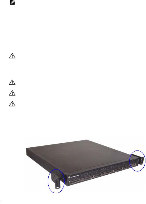
1Place the supplied rack-mounting bracket on one side of the switch, ensuring that the mounting holes on the switch line up to the mounting holes in the rack-mounting bracket. Figure 1 illustrates where to mount the brackets.
Figure 1. Attaching the Brackets
6 Getting Started Guide

2Insert the supplied bolts into the rack-mounting holes and tighten with a screwdriver.
3Repeat the process for the rack-mounting bracket on the other side of the switch.
4Insert the switch into the 48.26 cm (19 inch) rack, ensuring that the rack-mounting holes on the switch line up to the mounting holes in the rack.
5Secure the switch to the rack with either the rack bolts or cage nuts and cage nut bolts with washers (depending on the kind of rack you have). Fasten the bolts on bottom before fastening the bolts on top.
NOTICE: Make sure that the ventilation holes are not obstructed.
CAUTION: Make sure that the supplied rack bolts fit the pre-threaded holes in the rack.
Installing as a Free-standing Switch
NOTICE: We strongly recommend mounting the switch in a rack.
Install the switch on a flat surface if you are not installing it in a rack. The surface must be able to support the weight of the switch and the switch cables. The switch is supplied with four self-adhesive rubber pads.
1Attach the self-adhesive rubber pads on each location marked on the bottom of the switch.
2Set the switch on a flat surface, and make sure that it has proper ventilation by leaving 5 cm (2 inches) on each side and 13 cm (5 inches) at the back.
Connecting a Switch to a Terminal
1Connect the DB9 connector of the RJ-45-to-DB9 serial cable to a VT100 terminal or to a computer running VT100 terminal emulation software.
2Connect the RJ-45 connector at the other end to the top RJ-45 port on the rear panel of the switch. For more information about the location of the console port, see Figure 3.
Getting Started Guide |
|
7 |
|

w w w . d e l l . c o m | s u p p o r t . d e l l . c o m
Connecting a Switch to a Power Supply
CAUTION: Read the safety information in the Product Information Guide as well as the safety information for other switches that connect to or support the switch.
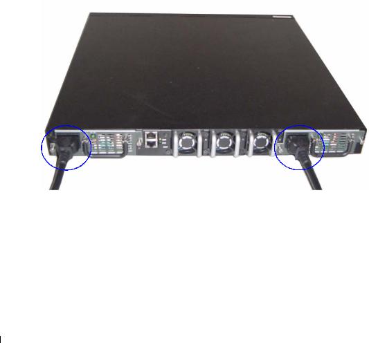
The PowerConnect 8024 and 8024F switches have two power supplies for redundant or loadsharing operation. Each power supply can support 300W. Figure 2 illustrates the location of the two power receptacles on the rear panel.
1Connect one of the supplied AC power cables to one of the AC power connectors located on the rear panel.
2To provide a redundant source of power, connect the second supplied AC power cable to the other AC power connector located on the rear panel.
NOTE: Do not connect the power cable to a grounded AC outlet at this time. Connect the switch to a power source as described in the step detailed in "Starting and Configuring the Switch".
Figure 2. Connecting Power Cables
8 Getting Started Guide
Starting and Configuring the Switch
After completing all external connections, connect a terminal to a switch to configure the switch. Additional advanced functions are described in the User's Guide located on your
User Documentation CD.
NOTE: Read the release notes for this product before proceeding. You can download the release notes from the Dell Support website at support.dell.com.
NOTE: We recommend that you obtain the most recent version of the user documentation from the Dell Support website at support.dell.com.
Connecting the Terminal to the Switch
To monitor and configure the switch via serial console, use the console port on the rear of the switch to connect it to a VT100 terminal or to a computer running VT100 terminal emulation software. The console port is implemented as a data terminal equipment (DTE) connector.
The following is required to use the console port:
•VT100-compatible terminal or a desktop or a portable system with a serial port, running VT100 terminal emulation software.
•A serial cable (provided) with a RJ-45 connector for the console port and DB9 connector for the terminal.
Perform the following tasks to connect a terminal to the switch console port:
1Connect the DB9 connector on the serial cable to the terminal running VT100 terminal emulation software.
2Configure the terminal emulation software as follows:
a Select the appropriate serial port (serial port 1 or serial port 2) to connect to the console. b Set the data rate to 9600 baud.
c Set the data format to 8 data bits, 1 stop bit, and no parity. d Set the flow control to none.
e Set the terminal emulation mode to VT100.
f Select Terminal keys for Function, Arrow, and Ctrl keys. Make sure that the setting is for Terminal keys (not Microsoft® Windows® keys).
NOTE: When using HyperTerminal with Microsoft Windows 2000, make sure that you have Windows 2000 Service Pack 2 or later installed. With Windows 2000 Service Pack 2, the arrow keys function properly in HyperTerminal's VT100 emulation. Go to www.microsoft.com for more information on Windows 2000 service packs.
3Connect the RJ-45 connector on the cable directly to the switch console port. The PowerConnect 8024 and 8024F console port is located on the rear panel, above the RJ-45 out-of-band port, as shown in Figure 3.
Getting Started Guide |
|
9 |
|

w w w . d e l l . c o m | s u p p o r t . d e l l . c o m
Figure 3. Connecting to the Console Port
Console Port
The RJ-45 port below the Console port is for out-of-band management.
Booting the Switch
1Make sure that the switch console port is connected to a VT100 terminal or VT100 terminal emulator via the RJ-45 to DB9 female cable.
2Locate two AC power receptacles.
3Deactivate the AC power receptacle.
4Connect both of the switch power supplies to the AC receptacles.
5Activate the AC power receptacles.
When the power is turned on with the local terminal already connected, the switch goes through a power-on self-test (POST). POST runs every time the switch is initialized and checks hardware components to determine if the switch is fully operational before completely booting. If POST detects a critical problem, the program flow stops. If POST passes successfully, valid firmware is loaded into RAM. POST messages are displayed on the terminal and indicate test success or failure. The boot process runs for approximately 60 seconds.
Initial Configuration
NOTE: The initial simple configuration procedure is based on the following assumptions:
•The PowerConnect switch was never configured before and is in the same state as when you received it.
•The PowerConnect switch booted successfully.
•The console connection was established and the Dell Easy Setup Wizard prompt appears on the screen of a VT100 terminal or terminal equivalent.
The initial switch configuration is performed through the console port. After the initial configuration, you can manage the switch either from the already-connected console port or remotely through an interface defined during the initial configuration.
NOTE: The switch is not configured with a default user name and password.
NOTE: All of the settings below are necessary to allow the remote management of the switch through Telnet (Telnet client) or HTTP (Web browser).
10 Getting Started Guide

Before setting up the initial configuration of the switch, obtain the following information from your network administrator:
•The IP address to be assigned to the management VLAN.
•The IP subnet mask for the network.
•The IP address of the management VLAN default gateway.
Management Interface and Out-of-Band Interface
The front panel of the PowerConnect 8024 and 8024F switches contains multiple 10-Gigabit Ethernet ports for data traffic. Additionally, you can use any port on the front panel as the in-band management interface. The rear panel contains a Gigabit Ethernet port for out-of-band (OOB) management. The OOB port is located below the console port.
The Dell Easy Setup Wizard configures network information for the in-band management interface. To use the OOB interface for management, use the Command Line Interface (CLI) to configure network information. You can assign a static IP address and subnet mask or enable DHCP and allow a DHCP server to assign the information automatically.
NOTE: DHCP can be enabled on either the management interface or the OOB interface, but not both. DHCP is enabled by default on the management interface. To use DHCP on the OOB interface, you must first disable it on the management interface and then enable it on the OOB interface.
See the PowerConnect 8024 and 8024F CLI Reference Guide for information about the commands to use to configure the OOB interface.
Initial Configuration Procedure
You can perform the initial configuration using the Dell Easy Setup Wizard, or by using the Command Line Interface (CLI). The Setup Wizard automatically starts when the switch configuration file is empty. You can exit the wizard at any point by entering [ctrl+z], but all configuration settings specified will be discarded (the switch will use the default values).
NOTE: If you do not run the Easy Setup Wizard or do not respond to the initial Easy Setup Wizard prompt within 60 seconds, the switch enters CLI mode. If the switch is connected to your network through the management interface when you power it on for the first time, it attempts to acquire an IP address from a DHCP server. If no DHCP server responds to the request within 50 seconds, the switch uses 192.168.2.1 as the default IP address on the management VLAN. To view the management interface IP address, enter the enable command to enter Privileged EXEC mode, and then enter show ip interface management. There is no default IP address for the OOB interface.
Getting Started Guide |
|
11 |
|

w w w . d e l l . c o m | s u p p o r t . d e l l . c o m
For more information on CLI initial configuration see the User Guide. This Getting Started Guide shows how to use the Setup Wizard for initial switch configuration. The wizard sets up the following configuration on the switch:
•Establishes the initial privileged user account with a valid password. The wizard configures one privileged user account during the setup.
•Enables CLI login and HTTP access to use the local authentication setting only.
•Sets up the IP address for the management VLAN.
•Sets up the SNMP community string to be used by the SNMP manager at a given IP address. You may choose to skip this step if SNMP management is not used for this switch.
•Allows you to specify the management server IP or permit management access from all IP addresses.
•Configures the default gateway IP address.
Example Session
This section describes an Easy Setup Wizard session. The following values are used by the example session:
•The SNMP community string to be used is public
•The network management system IP address is 192.168.2.1.
•The user name is admin, and password is admin123.
•The IP address for the management VLAN is 192.168.2.1:255.255.255.0.
•The default gateway is 0.0.0.0.
The setup wizard configures the initial values as defined above. After you complete the wizard, the switch is configured as follows:
•SNMPv1/2c is enabled and the community string is set up as defined above. SNMPv3 is disabled by default.
•The admin user account is set up as defined.
•A network management system is configured. From this management station, you can access the SNMP, HTTP, and CLI interfaces. You may also choose to allow all IP addresses to access these management interfaces by choosing the (0.0.0.0) IP address.
•An IP address is configured for the default management VLAN (1).
•A default gateway address is configured.
NOTE: In the example below, the possible user options are enclosed in [ ]. Also, where possible, the default value is provided in { }. If you press <Enter> with no options defined, the default value is accepted. Help text is in parentheses.
12 Getting Started Guide
The following example contains the sequence of prompts and responses associated with running an example Dell Easy Setup Wizard session, using the input values listed above.
After the switch completes the POST and is booted, the following dialog appears:
Unit 1 - Waiting to select management unit)>
Applying configuration, please wait ...
Welcome to Dell Easy Setup Wizard
The Setup Wizard guides you through the initial switch configuration, and gets you up and running as quickly as possible. You can skip the setup wizard, and enter CLI mode to manually configure the switch. You must respond to the next question to run the setup wizard within 60 seconds, otherwise the system will continue with normal operation using the default system configuration.Note: You can exit the setup wizard at any point by entering [ctrl+z].
Would you like to run the setup wizard (you must answer this question within 60 seconds)? [Y/N] y
Step 1:
The system is not setup for SNMP management by default. To manage the switch using SNMP (required for Dell Network Manager) you can
. Set up the initial SNMP version 2 account now.
. Return later and setup other SNMP accounts. (For more information on setting up an SNMP version 1 or 3 account, see the user documentation).
Would you like to setup the SNMP management interface now? [Y/N] y
To setup the SNMP management account you must specify the management system IP address and the "community string" or password that the particular management system uses to access the switch. The wizard automatically assigns the highest access level [Privilege Level 15] to this account. You can use Dell Network Manager or other management interfaces to change this setting and to add additional management systems later. For more information on adding management systems, see the User’s Guide.
Getting Started Guide |
|
13 |
|

w w w . d e l l . c o m | s u p p o r t . d e l l . c o m
To add a management station:
Please enter the SNMP community string to be used [public]:public
NOTE: If it is configured, the default access level is set to the highest available access for the SNMP management interface. Initially only SNMPv1/2c will be activated. SNMPv3 is disabled until you return to configure security access for SNMPv3 (e.g. engine ID, view, etc.).
Please enter the IP address of the Management System (A.B.C.D) or wildcard (0.0.0.0) to manage from any Management Station {0.0.0.0}: 192.168.2.100
Step 2:
Now we need to setup your initial privilege (Level 15) user account. This account is used to login to the CLI and Web interface. You may setup other accounts and change privilege levels later. For more information on setting up user accounts and changing privilege levels, see the user documentation.
To setup a user account:
Please enter the user name. [admin]:admin
Please enter the user password:********
Please reenter the user password:********
Step 3:
Next, an IP address is setup. The IP address is defined on the default VLAN (VLAN #1), of which all ports are members. This is the IP address you use to access the CLI, Web interface, or SNMP interface for the switch. Optionally you may request that the system automatically retrieve an IP address from the network via DHCP (this requires that you have a DHCP server running on the network).
To setup an IP address:
Please enter the IP address of the device (A.B.C.D) or enter "DHCP" (without the quotes) to automatically request an IP address from the network DHCP server. [192.168.2.1]:192.168.2.1
Please enter the IP subnet mask (A.B.C.D or /nn). [255.255.255.0]:255.255.255.0
14 Getting Started Guide

Step 4:
Finally, setup the default gateway. Please enter the IP address of the gateway from which this network is reachable. [0.0.0.0]:
This is the configuration information that has been collected:
SNMP Interface = "public"@192.168.2.100
User Account setup = admin
Password = ********
Management IP address = 192.168.2.1 255.255.255.0
Default Gateway = 0.0.0.0
Operation Mode = Normal
Step 5:
If the information is correct, please select (Y) to save the configuration, and copy to the start-up configuration file. If the information is incorrect, select (N) to discard configuration and restart the wizard: [Y/N] y
Thank you for using Dell Easy Set up Wizard. You will now enter CLI mode.
Advanced Configuration
This section provides summary information about such common tasks as:
•Retrieving an IP Address From a DHCP Server
•Security Management and Password Configuration
NOTE: For detailed information on all the CLI commands available for the 8024 and 8024F M6348 switches, see the CLI Reference Guide.
Retrieving an IP Address From a DHCP Server
When using the DHCP protocol to retrieve an IP address, the switch acts as a DHCP client. To retrieve an IP address from a DHCP server, perform the following steps:
1Select and connect any port to a DHCP server or to a subnet that has a DHCP server on it, in order to retrieve the IP address.
NOTE: You do not need to delete the switch configuration to retrieve an IP address for the D HCP server.
2Enter the following commands to use the selected port for receiving the IP address. console#config
console(config)#ip address dhcp
The interface receives the IP address automatically.
Getting Started Guide |
|
15 |
|

w w w . d e l l . c o m | s u p p o r t . d e l l . c o m
3To verify the IP address, enter the show ip interface command at the system prompt as shown in the following example.
console#show ip interface
Management Interface:
IP Address....................................... |
|
|
10.240.4.125 |
|
Subnet Mask |
..................................... |
|
255.255.255.0 |
|
Default Gateway.................................... |
|
|
10.240.4.1 |
|
Burned In MAC Address........................ |
|
00:10:18:82:04:35 |
||
Network Configuration Protocol Current................... |
|
DHCP |
||
Management |
VLAN ID.......................................... |
|
|
1 |
Routing Interfaces: |
|
|
|
|
|
|
Netdir Multi |
|
|
Interface |
IP Address |
IP Mask |
Bcast |
CastFwd |
---------- |
--------------- --------------- -------- |
-------- |
||
vlan1 |
192.168.10.10 |
255.255.255.0 |
Disable |
Disable |
vlan2 |
0.0.0.0 |
0.0.0.0 |
Enable |
Disable |
loopback2 |
0.0.0.0 |
0.0.0.0 |
Disable |
Disable |
Security Management and Password Configuration
System security is handled through the AAA (Authentication, Authorization, and Accounting) mechanism that manages user access rights, privileges, and management methods. AAA uses both local and remote user databases. Data encryption is handled through the SSH mechanism.
The system is delivered with no default password configured; all passwords are user-defined. If a user-defined password is lost, a password recovery procedure can be invoked from the Boot menu. The procedure is applicable for the local terminal only and allows a one-time access to the switch from the local terminal with no password entered.
16 Getting Started Guide

Configuring Security Passwords
The security passwords can be configured for the following services:
•Console
•Telnet
•SSH
•HTTP
•HTTPS
NOTE: When creating a user name, the default priority is "1", which allows access but not configuration rights. A priority of "15" must be set to enable access and configuration rights to the switch.
Configuring an Initial Console Password
To configure an initial console password, enter the following commands:
console(config)#aaa authentication login default line
console(config)#aaa authentication enable default line
console(config)#line console
console(config-line)#login authentication default
console(config-line)#enable authentication default
console(config-line)#password secret123
•When initially logging on to a switch through a console session, enter secret123 at the password prompt.
•When changing a switch’s mode to enable, enter secret123 at the password prompt.
Configuring an Initial Telnet Password
To configure an initial Telnet password, enter the following commands:
console(config)#aaa authentication login default line
console(config)#aaa authentication enable default line
console(config)#line telnet
console(config-line)#login authentication default
console(config-line)#enable authentication default
console(config-line)#password pass1234
•When initially logging onto a switch through a Telnet session, enter pass1234 at the password prompt.
•When changing a switch mode to enable, enter pass1234.
Getting Started Guide |
|
17 |
|

w w w . d e l l . c o m | s u p p o r t . d e l l . c o m
Configuring an Initial HTTP Password
To configure an initial HTTP password, enter the following commands: console(config)#ip http authentication local console(config)#username admin password user1234 level 15
Configuring an Initial HTTPS Password
To configure an initial HTTPS password, enter the following commands:
console(config)#ip https authentication local
NOTE: You should generate a new crypto certificate each time you upgrade (install a new version of) the control software application on the switch.
Enter the following commands once when configuring to use an HTTPS session over a console, a Telnet, or an SSH session.
NOTE: In the Web browser enable SSL 2.0 or greater for the page content to appear.
console(config)#crypto certificate 1 generate
console(config)#ip https server
NOTE: Http and Https services require level 15 access and connect directly to the configuration level access.
18 Getting Started Guide
Managing the Switch
You can manage the switch by using the Web-based interface, command-line interface (CLI), or SNMP. To manage the switch by using a Web browser or SNMP, the switch must have an IP address, and it must be accessible from the management station. To manage the switch by using the CLI, you can use a direct console connection or a remote Telnet/SSH connection.
To establish a direct console connection to the CLI, see "Connecting the Terminal to the Switch" on page 9. You can use the Easy Setup Wizard To perform the initial configuration that allows remote management access (see "Initial Configuration Procedure" on page 11). For instructions on configuring remote management using the CLI, refer to the User’s Guide.
Using a Web Browser to Manage the Switch
Starting the Application
1Open a web browser.
2Enter the switch’s IP address (as defined in the CLI) in the address bar and press <Enter>.
For information about assigning an IP address to a switch, see "Initial Configuration" on page 10.
3When the Login window displays, enter a user name and password.
NOTE: The switch is not configured with a default password, and you can configure the switch without entering a password when you connect to the CLI by using the console port. Passwords are both case sensitive and alpha-numeric. For information about recovering a lost password, see the User’s Guide.
4Click OK.
5The Dell OpenManage Switch Administrator home page displays.
Understanding the Interface
The home page contains the following views:
•Tree view — Located on the left side of the home page, the tree view provides an expandable view of features and their components.
•Device view — Located on the right side of the home page, the device view is used to display such things as a view of the device, an information or table area, and/or configuration instructions.
Getting Started Guide |
|
19 |
|

w w w . d e l l . c o m | s u p p o r t . d e l l . c o m
Guide Started Getting 20
Dell™ PowerConnect™
8024 8024F
PC8024 PC8024F
w w w . d e l l . c o m | s u p p o r t . d e l l . c o m
 “ ”
“ ”
 “ ”
“ ”
 “ ”
“ ”
____________________
© 2009 Dell Inc.
Dell Inc.
Dell DELL PowerConnect Dell Inc. Microsoft Windows Microsoft Corporation
Dell Inc.
PC8024 PC8024F
2009 11 |
P/N X472K |
Rev. A02 |

. . . . . . . . . . . . . . . . . . . . . . . . . . . . . . . . .
. . . . . . . . . . . . . . . . . . . . . . . . . . . . .
. . . . . . . . . . . . . . . . . . . . . . . . . . . . .
. . . . . . . . . . . . . . . . . . . . . . . . . . . .
. . . . . . . . . . . . . . . . . . . . . . . . . . . . . . . .
. . . . . . . . . . . . . . . . . . . . . . . . . . . .
. . . . . . . . . . . . . . . . . . . . . . . .
. . . . . . . . . . . . . . . . . . . . . . . . . . .
. . . . . . . . . . . . . . . . . . . . . . . .
25
25
25
26
26
26
27
27
28
. . . . . . . . . . . . . . . . . . . . . . . . . . .
. . . . . . . . . . . . . . . . . . . . . . . . . . . . . . . .
. . . . . . . . . . . . . . . . . . . . . . . . . . . . . . . . .
. . . . . . . . . . . . . . . . . . . . . . . .
. . . . . . . . . . . . . . . . . . . . . . . . . . . .
. . . . . . . . . . . . . . . . . . . . . . . . . . . . . . .
. . . . . . . . . . . . . . . . . . . . . . . . . . . . . . . . .
DHCP IP . . . . . . . . . . . . . . . . . . . . .
. . . . . . . . . . . . . . . . . . . . . .
29
30
30
31
31
32
35
35
37
Web . . . . . . . . . . . . . . . . . . . . . . . 39. . . . . . . . . . . . . . . . . . . . . . . . . . . . 39. . . . . . . . . . . . . . . . . . . . . . . . . . . . . . . 39
23

24

Dell™ PowerConnect™ 8024 8024FUser Documentation CD Dellsupport.dell.com
PowerConnect 8024 8024F 48.26 19
•- 100-250 VAC 50-60 Hz
•-
•-
•- 0 45oC 32 113oF 95%
•PowerConnect
•RJ-45 DB9
•User Documentation CD
25

w w w . d e l l . c o m | s u p p o r t . d e l l . c o m


1 固定孔对齐。图1
1.
26

448.26 19


以及交换机电缆的重量。
25 2 135
1RJ-45 DB9 DB9 VT100 VT100
2RJ-45 RJ-453
27
w w w . d e l l . c o m | s u p p o r t . d e l l . c o m

PowerConnect 8024 8024F300W 2
2 源连接器。
 “ ”
“ ”
2.
28
Loading...