


Dell™ PowerConnect™ 5224 Systems User's Guide
Caution: Safety Instructions
Introduction
Installation
Management Interface
VLANs
Appendix
Notes, Notices, and Cautions
NOTE: A NOTE indicates important information that helps you make better use of your computer.
NOTICE: A NOTICE indicates either potential damage to hardware or loss of data and tells you how to avoid the problem.
CAUTION: A CAUTION indicates a potential for property damage, personal injury, or death.
Information in this document is subject to change without notice.
© 2002 Dell Computer Corporation. All rights reserved.
Reproduction in any manner whatsoever without the written permission of Dell Computer Corporation is strictly forbidden.
Trademarks used in this text: Dell, the DELL logo, PowerConnect, Dimension, Inspiron, Dell Precision, OptiPlex, Latitude, and DellNet are trademarks of Dell Computer Corporation; Microsoft and Windows are registered trademarks of Microsoft Corporation.
Other trademarks and trade names may be used in this document to refer to either the entities claiming the marks and names or their products. Dell Computer Corporation disclaims any proprietary interest in trademarks and trade names other than its own.
August 2002 P/N 5P788 Rev. A01

Back to Contents Page
Introduction
Dell™ PowerConnect™ 5224 Systems User's Guide
Features
Front-Panel Components
Back-Panel Descriptions
Management
Features
The Dell™ PowerConnect™ 5224 Gigabit Ethernet Managed Switch offers the following features:
•24 10/100/1000BASE-T auto-sensing Gigabit Ethernet switching ports
•Four 10/100/1000BASE-T ports operate in combination with four Small Form Factor Pluggable (SFP) transceiver slots
•IEEE 802.3u, IEEE 802.3z, and IEEE 802.3ab compliant
•Up to 32 kilobyte (KB)-entry, media access control (MAC) address cache
•IEEE 802.3x flow control for full duplex operation
•IEEE 802.1Q based tagged virtual local area network (VLAN)
•IEEE 802.1p Class of Service (CoS) through four priority queues for each port
•IEEE 802.3ad link aggregation: up to six aggregated trunks per switch
•Support for jumbo frames up to 9 KB
•Spanning tree protocol
•Broadcast storm control
•Internet group management protocol (IGMP) snooping support
•Back pressure flow control for half-duplex operation
•Port mirroring
•Auto MDI/MDIX support for the 10/100/1000BASE-T ports
•MAC addresses lookup based on port, VLAN ID, and MAC addresses
•Redundant power supply (RPS) support for uninterrupted operation
•System light-emitting diode (LED) and per port LEDs
•Standard 1U chassis
•19-inch rack-mountable
Management Features
•Web-based management with embedded HTTP server
•Text-based management through four in-band Telnet sessions, and an out-of-band RS-232 console port (VT100)
•Simple network management protocol (SNMP)-based network management through an SNMP management console program
•RADIUS access control
•Software upload through Trivial File Transfer Protocol (TFTP)
•Dual firmware image support
•Supports Boot Protocol (BOOTP) and Dynamic Host Configuration Protocol (DHCP) for IP address assignment
•Hardware-assisted remote monitoring (RMON) statistic collection
•Management information base (MIB) II (RFC 1213)
•Interfaces Evolution MIB (RFC 2863)
•Ethernet-like MIB (RFC 2665)
•Bridge MIB (RFC 1493)
•Extended Bridge MIB (RFC 2674)
•RMON MIB (RFC 2819)
•Entity MIB (RFC 2737)
•RADIUS authentication client MIB (RFC 2618)
•Dell PowerConnect 5224 Private MIB

Front-Panel Components
The front panel of the switch contains the console port, all of the Ethernet ports, and LEDs. As shown in the following figure, the switch has three system LEDs and one LED for each port. The following sections describe the front panel in more detail.
PWR LED
The PWR (power) LED shows the general operating status of the system. Indicator states include:
•Off — The unit is off with no power connections.
•Green — The unit's internal power supply is operating normally.
•Red — The unit's internal power supply has failed.
RPS LED
The RPS LED shows the operating status of a connected redundant power unit. Indicator states include:
•Off — The RPS is not connected.
•Green — The RPS is operating normally.
•Red — The RPS has failed.
DIAG LED
The diagnostic (DIAG) LED shows the status of the system diagnostics during initialization. Indicator states include:
•Blinking green — The system diagnostic test is in progress.
•Green — The system diagnostic test has completed successfully.
•Red — The system diagnostic test has detected a fault.
Console Port
You can access the console interface from the RS-232 serial port or a Telnet connection. The console port uses a standard null-modem cable. For instructions on configuring your switch using the console, see "Management Interface."
Port LEDs
Two of the LEDs show the operating status of each Gigabit Ethernet port, and the other LED shows the operating status of each SFP transceiver slot. Details of the LED indications are provided in each of the following sections.
Gigabit Ethernet Ports
Link Status and Activity (LINK/ACT)
•Green — A 1000-megabits per second (Mbps) link is up and there is no activity.
•Blinking green — A 1000-Mbps link is up and there is activity.
•Orange — A 10/100-Mbps link is up and there is no activity.
•Blinking orange — A 10/100-Mbps link is up and there is activity.
•Flashing orange — The link is in the admin down state.
•Off — The link is down.
Duplex Mode (FDX)
•Green — A full-duplex link is up.
•Off — A half-duplex link is up.
SFP Transceiver Ports
SFP Transceiver Status
•Green — An SFP transceiver is correctly installed in the slot.
•Off — An SFP transceiver is not installed in the slot.

Back-Panel Descriptions
The back panel of the system contains the AC power receptacle and the RPS connector.
AC Power Receptacle
The switch automatically adjusts its power setting to any supply voltage in the range of 90 to 240 V alternating current (VAC).
RPS Connector
Connect the optional RPS to the RPS connector. If the switch's internal power unit fails, the redundant power system automatically supplies power to the switch for uninterrupted operation.
The switch supports the Dell PowerConnect RPS-600 external redundant power system.
NOTE: See the RPS-600 documentation for more information.
CAUTION: Do not use this switch with any redundant power system other than the Dell PowerConnect RPS-600.
Management
The following sections describe options for managing the switch.
Web-Based Interface
NOTE: To access the switch through a web browser, the computer running the web browser must have IP-based network access to the switch.
After you have successfully installed the switch, you can configure the switch, monitor the LED panel, and display statistics graphically using a web browser, such as Netscape Navigator (version 6.2 and higher) or Microsoft® Internet Explorer (version 5.0).
Command-Line-Driven Console Interface Through a Serial Port or Telnet
You can also connect a computer or terminal to the serial console port or use Telnet to access the switch. The command-line-driven interface provides complete access to all switch management features. Most of the common commands are described in "Management Interface." For a full list of commands, see the Command Line Reference, which is included on the documentation CD.
SNMP-Based Management
You can manage the switch with an SNMP-compatible console program. The switch is compatible with SNMP version 1.0.
The SNMP agent decodes the incoming SNMP messages and responds to requests with MIB objects stored in the database. The SNMP agent updates the MIB objects every 5 seconds to generate statistics and counters.
The switch supports a comprehensive set of MIB extensions:
•RFC 1213 MIB II
•RFC 2863 Interfaces Evolution MIB
•RFC 2665 Ethernet-Like MIB
•RFC 1493 Bridge MIB
•RFC 2674 Extended Bridge MIB
•RFC 2819 RMON MIB
•RFC 2737 Entity MIB
•RFC 2618 RADIUS authentication client MIB
•Dell PowerConnect 5224 Private MIB
Back to Contents Page

Back to Contents Page
Installation
Dell™ PowerConnect™ 5224 Systems User's Guide
Package Contents |
Password Protection |
Before You Connect to the Network: Mounting Kit Instructions |
SNMP Settings |
External Redundant Power System |
IP Address Assignment |
Connecting the Console Port |
Connecting Devices to the Switch |
|
|
Package Contents
Before you begin installing the switch, confirm that your package contains the following items:
•Switch
•AC power cable
•Null modem cable
•Self-adhesive rubber pads for desktop installation
•Rack mount kit for rack installation
•Documentation CD
Before You Connect to the Network: Mounting Kit Instructions
NOTICE: Do not connect the switch to the network until you have established the correct Internet Protocol (IP) settings.
Before you connect to the network, you must install the switch on a flat surface or in a rack, set up a terminal emulation program, plug in the power cord, and then set up a password and IP address.
The switch is supplied with rubber feet for stationing it on a flat surface and mounting brackets and screws for mounting the switch in a rack.
Installing the Switch Without the Rack
Install the switch on a level surface that can safely support the weight of the switch and its attached cables. The switch must have adequate space for ventilation and for accessing cable connectors.
1.Set the switch on a flat surface and check for proper ventilation.
Allow at least 2 inches (5.1 centimeters [cm]) on each side of the switch and 5 inches (12.7 cm) at the back for the power cable.
2.Attach the rubber feet on the marked locations on the bottom of the chassis.
The rubber feet, although optional, are recommended to keep the unit from slipping.
Installing the Switch in a Rack
You can install the switch in most standard 19-inch (48.3-cm) racks.
NOTE: For racks that are not prethreaded, cage nuts are provided.
1.Use the supplied screws to attach a mounting bracket to each side of the switch.
2.Align the holes in the mounting bracket with the holes in the rack.
3.Insert and tighten two screws through each of the mounting brackets.
External Redundant Power System
The switch supports the Dell PowerConnect RPS-600 external redundant power system.
NOTE: See the RPS-600 documentation for more information.
CAUTION: Do not use the switch with any redundant power system other than the Dell PowerConnect RPS-600.
Connecting the Console Port

The switch provides an RS-232 serial port that enables a connection to a computer or terminal for monitoring and configuring the switch. This port is a male DB-9 connector, implemented as a data terminal equipment (DTE) connection.
To use the console port, you need the following equipment:
•A terminal or a computer with both a serial port and the ability to emulate a terminal
•A null modem or crossover RS-232 cable with a female DB-9 connector for the console port on the switch
To connect a terminal to the console port:
1.Connect the female connector of the RS-232 cable directly to the console port on the switch, and tighten the captive retaining screws.
2.Connect the other end of the cable to a terminal or to the serial connector of a computer running terminal emulation software.
Set the terminal emulation software as follows:
a.Select the appropriate serial port (COM port 1 or COM port 2).
b.Set the data rate to 9600 baud.
c.Set the data format to 8 data bits, 1 stop bit, and no parity.
d.Set flow control to none.
e.Under Properties, select VT100 for Emulation mode.
f.Select Terminal keys for Function, Arrow, and Ctrl keys. Ensure that you select Terminal keys (not Windows keys).
NOTICE: When you use HyperTerminal with the Microsoft® Windows® 2000 operating system, ensure that you have Windows 2000 Service Pack 2 or later installed. Windows 2000 Service Pack 2 allows you to use arrow keys in HyperTerminal's VT100 emulation. See www.microsoft.com for information on Windows 2000 service packs.
3.After you have correctly set up the terminal, plug the power cable into the power receptacle on the back of the switch. The boot sequence appears in the terminal.
4.After the boot sequence completes, the console login screen displays. If you have not logged into the command line interface (CLI) program, the default user names are admin and guest, and the corresponding passwords are admin and guest.
•If you log in as guest, the CLI displays the Console> prompt to indicate that you are using the CLI in normal access (Normal Exec) mode.
•If you log in as admin, the CLI displays the Console# prompt to indicate that you are using the CLI in privileged access (Privileged Exec) mode.
5.Enter the commands to complete your desired tasks. Many commands require Privileged Exec-level access.
CLI commands for most common tasks are provided in "Management Interface." See the Command Line Reference on the documentation CD for a list of all commands and additional information on using the CLI.
6.When you have completed your tasks, exit the session with the Quit command.
Password Protection
To proceed through the CLI initial login screen, you must enter a password. If you have not logged into the CLI program, the default user names are admin and guest, and the corresponding passwords are admin and guest. If you log in as guest, you have access to the Normal Exec level. If you log in as admin, you have access to the Privileged Exec level.
User Access Verification
Username: admin
Password:
CLI session with the PowerConnect 5224 is opened.
To end the CLI session, enter [Exit].
Console#
After your initial login, define new passwords for both default user names to prevent unauthorized access to the switch, and record the passwords for future reference.
1.At the CLI login prompt, enter admin as the user name and password for the Privileged Exec level. Press <Enter>.
2.Type configure and press <Enter>.
NOTE: Passwords are case sensitive.
3.To set the Normal Exec level password, type username guest password 0 password, where password is your new password (up to eight characters). Press <Enter>.
4.To set the Privileged Exec level password, type username admin password 0 password, where password is your new password (up to eight characters). Press <Enter>.
5.To save your configuration changes, type copy running-config startup-config and then press <Enter>.

NOTICE: CLI configuration commands only modify the running configuration file and are not saved when the switch is rebooted. To save all your configuration changes in nonvolatile storage, you must use the copy command to copy the running configuration file to the startup configuration.
SNMP Settings
Simple Network Management Protocol (SNMP) is a protocol designed specifically for managing devices on a network. Network equipment, such as hubs, switches, and routers, use SNMP to configure system features for proper operation, as well as to monitor their performance and detect potential problems.
Managed devices that support SNMP include software (referred to as an agent), which runs locally on the device. A defined set of variables (managed objects) is maintained by the SNMP agent and used to manage the device. These objects are defined in a Management Information Base (MIB), which provides a standard presentation of the information controlled by the agent. SNMP defines both the format of the MIB specifications and the protocol used to access this information over the network.
The PowerConnect 5224 switch includes an on-board SNMP agent that monitors the status of the switch hardware, as well as the traffic passing through the ports. A computer on the network running SNMP-based management software, called a Network Management Station (NMS), can be used to access this information. Access rights to the SNMP agent are controlled by community strings. To communicate with the switch, the NMS must first submit a valid community string for authentication.
The default community strings for the switch are:
•public — Allows authorized management stations to retrieve MIB objects.
•private — Allows authorized management stations to retrieve and modify MIB objects.
If you do not intend to utilize SNMP, delete both of the default community strings. SNMP management access to the switch is disabled if no community strings exist. To delete the strings:
1.If you are not already in the Privileged Exec level global configuration mode, type configure and press <Enter>.
2.To delete the private community string, type no snmp-server community private and then press <Enter>.
3.To delete the public community string, type no snmp-server community public and then press <Enter>.
4.To save your configuration changes, type copy running-config startup-config and then press <Enter>.
If you do intend to utilize SNMP, change the default community strings to prevent unauthorized access to the switch:
1.If you are not already in the Privileged Exec level global configuration mode, type configure and press <Enter>.
2.To delete the existing private community string, type no snmpserver community private and then press <Enter>.
3.Type snmp-server community string rw, where string is your new community string (case sensitive) for read-write access. Press <Enter>.
4.To delete the existing public community string, type no snmpserver community public and then press <Enter>
5.Type snmp-server community string ro, where string is your new community string (case sensitive) for read-only access. Press <Enter>.
6.To save your configuration changes, type copy running-config startup-config and then press <Enter>.
IP Address Assignment
You must assign an IP address to the switch to gain management access over the network. You may also need to a establish a default gateway between the switch and management stations that exist on another network segment. You can statically configure a specific IP address or direct the switch to obtain an address from a Boot Protocol (BOOTP) or Dynamic Host Configuration Protocol (DHCP) server when it is powered on. Valid IP addresses consist of four decimal numbers, 0 to 255, separated by periods. Anything outside this format is not accepted by the CLI program.
NOTICE: By default, the IP address is assigned to VLAN 1 through DHCP.
If you select the bootp or dhcp option, IP is enabled but does not function until a BOOTP or DHCP reply has been received. Requests are broadcast periodically by the switch in an effort to learn its IP address. (BOOTP and DHCP values can include the IP address, default gateway, and subnet mask).
To display assigned IP settings using the CLI:
1.From the Privileged Exec or Normal Exec level mode, type show ip interface and press <Enter>.
The assigned IP address and subnet mask displays.
2.From the Privileged Exec mode, type show ip redirects to display the assigned gateway IP address. Press <Enter>.
The following example displays IP settings assigned by bootp or dhcp using the CLI.
Console#show ip interface
IP address and netmask: 10.1.0.1 255.255.252.0 on VLAN 1,
and address mode: User specified.
Console# show ip redirects
ip default gateway 10.1.0.254
Console#

Before you can assign a static IP address to the switch, you must obtain the following information from your network administrator:
•IP address for the switch
•Default gateway for the network
•Network mask for the network
To assign a static IP address to the switch:
1.From the Privileged Exec level global configuration mode prompt, type interface vlan 1 to access the interface-configuration mode. Press <Enter>.
2.Type ip address ip-address netmask, where ip-address is the switch IP address and netmask is the network mask for the network.
3.Type exit to return to the global configuration mode prompt. Press <Enter>.
4.To set the IP address of the default gateway for the network to which the switch belongs, type ip default-gateway gateway, where gateway is the IP address of the default gateway. Press <Enter>.
5.To save your configuration changes, type copy running-config startup-config and then press <Enter>.
NOTICE: Only one VLAN can be assigned an IP address. If you assign an address to any other VLAN, the new address overrides the original IP address.
The following example shows how to set a static IP address using the CLI.
Console(config)# interface vlan 1
Console(config-if)# ip address 192.168.1.5 255.255.255.0
Console(config-if)# exit
Console(config)# ip default-gateway 192.168.1.254
Console(config)#
To configure the switch for DHCP or BOOTP:
1.From the Privileged Exec level global configuration mode prompt, type interface vlan 1 to access the interface-configuration mode. Press <Enter>.
2.At the next prompt, use one of the following commands:
•To obtain IP settings through DHCP, type ip address dhcp
•To obtain IP setting through BOOTP, type ip address bootp
3.Press <Enter>.
4.To save your configuration changes, type copy running-config startup-config, and then press <Enter>.
Connecting Devices to the Switch
After you assign IP addresses to the switch, you can connect devices to the RJ-45 connectors on the switch.
NOTICE: If autonegotiation is disabled for an RJ-45 port, the auto- MDI/MDI-X pin signal configuration is also disabled.
To connect a device to an SFP transceiver port:
1.Use your cabling requirements to select an appropriate SFP transceiver type.
2.Insert the SFP transceiver (sold separately) into the SFP transceiver slot. The slot's LED indicator turns on to confirm that it is correctly installed.
3.Use the appropriate network cabling to connect a device to the connectors on the SFP transceiver.
NOTICE: When the SFP transceiver acquires a link, the associated integrated 10/100/1000BASE-T port is disabled.
Back to Contents Page

Back to Contents Page
Management Interface
Dell™ PowerConnect™ 5224 Systems User's Guide
Web Pages |
VLAN |
System |
Class of Service |
Switch |
Link Aggregation |
Ports |
SNMP |
Address Table |
Multicast Support |
Spanning Tree |
Statistics |
With web-based management, you can configure the PowerConnect 5224 Gigabit Ethernet Managed Switch and monitor the system using a web browser.
Most pages for the switch include the following buttons:
•Refresh — Displays the current values for the system related to the page that is open.
•Apply Changes — Makes changes to the system and refreshes the page.
NOTICE: For configuration changes to persist beyond the current session, you must either save the running-config file from the Switch/Configuration page or use the command line interface (CLI) command copy running-config startup-config.
Web Pages
When you connect to the management mode of the switch with a web browser, a login screen is displayed. Enter a user name and password to access the switch's management mode.
NOTE: The default user names are admin and guest, and the corresponding passwords are admin and guest. If you log in as guest (Normal Exec level), you can only view page information and change the guest password. If you log in as admin (Privileged Exec level), you can apply changes on all pages.
The following menus are available from the web interface:
•Switch
•Ports
•Address Table
•Spanning Tree
•VLAN
•Class of Service
•Link Aggregation
•SNMP
•Multicast Support
•Statistics
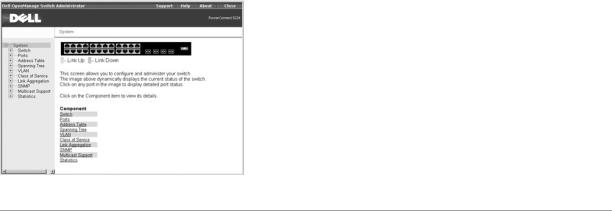
System
The System page contains a dynamic switch applet that displays the current status of the switch ports. The color of each switch port icon indicates its link status:
•Green — The link is up.
•Grey — The link is down.
Clicking on any port icon displays the port configuration page.
Switch
The Switch page contains all system operations and general information. It includes links to the following options:
•General — Allows you to view general system information and perform general administration.
•IP Address — Allows you to view or edit Internet Protocol (IP) parameters.
•Security — Allows you to set the password for your login username.
•Firmware — Allows you to transfer a firmware upgrade to the switch.
•Configuration — Allows you to save or restore switch configuration files.
•Reset — Allows you to reboot the switch.
General Information
The General page contains links to the following pages:
•Asset
•Health
•Versions
•Logs
Asset
The Asset page contains the following information:
•MAC Address
•SNMP Object ID
•System Up Time
It also includes the following editable fields:
•System Name
•System Contact
•System Location
To save any changes you make in this page, click Apply Changes. If you don't want to save the changes, click Refresh.
CLI Commands
The following table summarizes the equivalent CLI commands for items in the Switch/General/Asset page.
Command |
Usage |
|
|
show system |
Displays system information |
|
|
hostname name |
Specifies or modifies the system name for this device |
|
|
snmp-server contact string |
Sets the system contact (sysContact) string |
|
|
snmp-server location text |
Sets the system location string |
Example
Console(config)#hostname Server Chassis 35
Console(config)#snmp-server contact Paul
Console(config)#snmp-server location WC-19
Console(config)#exit
Console#show system
System description: PowerConnect 5224
System OID string: 1.3.6.1.4.1.674.10895.4
System information
System Up time: 0 days, 0 hours, 14 minutes, and 17.93 seconds
System Name |
: Server Chassis 35 |
System Location |
: WC-19 |
System Contact |
: Paul |
MAC address |
: 00-00-e8-00-00-02 |
Web server |
: enable |
Web server port |
: 80 |
POST result |
: |
--- Performing Power-On Self Tests (POST) ---
UART Loopback Test ..................... |
PASS |
Timer Test ............................. |
PASS |
CACHE Test.............................. |
PASS |
DRAM Test .............................. |
PASS |
I2C Initialization ..................... |
PASS |
Runtime Image Check .................... |
PASS |
PCI Device Check ....................... |
PASS |
Switch Driver Initialization ........... |
PASS |
------------------- DONE --------------------
Console#
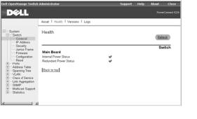
Health
The Health page contains the following information:
•Internal Power Status
•Redundant Power Status
The power status is indicated by the following icons:
•Green check — Power is connected and operating.
•Red cross — Power is connected but has failed.
•Not present — Power is not connected.
To reset these fields to their current value, click Refresh.
CLI Commands
The following table summarizes the equivalent CLI command for items in the Switch/General/Health page.
Command |
Usage |
|
|
|
|
show |
Displays hardware and software version information for the system, as well as the unit's |
|
version |
power status |
|
|
|
|
Example |
|
|
Console#show version |
|
|
Unit1 |
|
|
Serial number |
:123457 |
|
Service tag |
:3 |
|
Hardware version |
:/2002 |
|
Number of ports |
:24 |
|
Master power status |
:up |
|
Backup power status |
:up |
|
Agent(master) |
|
|
Unit id |
:1 |
|
Loader version |
:0.0.5.5 |
|
Boot rom version |
:0.0.6.0 |
|
Operation code version :0.2.0.0
Console#
Versions
The Versions page contains the following fields:

•Hardware Version
•Microcode Version
•Loader Version
•Boot-ROM Version
•Operation Code Version
•Total Port Number
•Role
•Service Tag
•Serial Number
CLI Commands
The following table summarizes the equivalent CLI command for items in the Switch/General/Versions page.
Command |
Usage |
|
|
|
|
show |
Displays hardware and software version information for the system, as well as the unit's |
|
version |
power status |
|
Example |
|
|
Console#show version |
|
|
Unit1 |
|
|
Serial number |
:123457 |
|
Service tag |
:3 |
|
Hardware version |
:/2002 |
|
Number of ports |
:24 |
|
Master power status |
:up |
|
Backup power status |
:up |
|
Agent(master) |
|
|
Unit id |
:1 |
|
Loader version |
:0.0.5.5 |
|
Boot rom version |
:0.0.6.0 |
|
Operation code version :0.2.0.0
Console#
Logs
The Logs page allows you to scroll through the logged system and event messages. The switch can store up to 2 kilobytes (KB) of log entries in temporary random access memory (RAM) (memory flushed on power reset) and up to 4 KB of entries in permanent flash memory.

CLI Commands
The following table summarizes the equivalent CLI commands for items in the Switch/General/Logs page.
Command |
Usage |
show logging {flash | ram} Displays the logging configuration for system and event messages
flash — event history stored in flash memory (permanent memory)
ram — event history stored in temporary RAM (memory flushed on power reset)
NOTE: The CLI allows you to configure and limit system messages that are logged to flash or RAM memory. The show logging command only displays the current logging configuration.
The system log messages are categorized by severity into eight levels, from 0 (Emergencies) to 7 (Debugging). The CLI command logging history allows you to specify which messages are logged to RAM or flash memory. The default is for messages with severity levels of 0 to 3 to be logged to flash and levels 0 to 7 to be logged to RAM.
Severe error messages that are logged to flash memory are permanently stored in the switch to assist in troubleshooting network problems. Up to 4 KB of message entries can be stored in the flash memory, with older messages being overwritten first when this memory capacity has been exceeded.
Example
Console#show logging flash
Syslog logging: Disable
History logging in FLASH: level errors
Console#
IP Address
The IP Address page contains links to the following pages:
•IP Address
•DHCP
IP Address
From the IP Address page, you can manage the IP-related information about the system. The page includes the following editable fields:
•Management VLAN — Sets the virtual local area network (VLAN) interface that allows management access to the switch. You can set the IP address for only one VLAN interface.
•IP Address Mode — Sets whether IP functionality is enabled through manual (Static) configuration or set by Dynamic Host Configuration Protocol (DHCP) or Boot Protocol (BOOTP).
•IP Address — Identifies the IP address of the VLAN interface that allows management access to the switch.
•Subnet Mask — Identifies the subnet mask that determines the host address bits used for routing to specific subnets.
•Gateway IP Address — Identifies the IP address of the gateway router between the switch and management stations that exist on other network segments.
NOTICE: When DHCP or BOOTP has been used to set the IP information, the IP Address, Subnet Mask, and Gateway IP Address fields display the assigned values.
The Management VLAN is the only VLAN through which you can gain management access to the switch. By default, all ports on the switch are members of VLAN 1, so a management station can be connected to any port on the switch. If other VLANs are configured and you change the Management VLAN, you may lose management access to the switch. In this case, you should reconnect the management station to a port that is a member of the Management VLAN. For more information on the Management VLAN, see "Management VLAN Access."
To save any changes you make in this page, click Apply Changes. If you don't want to save the changes, click Refresh.

CLI Commands
The following table summarizes the equivalent CLI commands for items in the Switch/IP Address page.
Command |
Usage |
|
|
ip address {ip-address |
Sets the primary IP address for this device. Use the no form command to |
netmask | bootp | dhcp} |
remove the IP address, or to disable IP address assignment through BOOTP or |
|
DHCP. |
|
|
ip default-gateway |
Establishes a static route between the switch and management stations that |
gateway |
exist on another network segment. |
|
|
show ip interface |
Displays the usability status of an IP interface. |
|
|
show ip redirects |
Shows the default gateway configured for this device. |
|
|
Example
Console(config)#interface vlan 1
Console(config-if)#ip address 192.168.1.5 255.255.255.0
Console(config-if)#exit
Console(config)#ip default-gateway 192.168.1.254
Console(config)#
DHCP
In the DHCP page, click Restart DHCP to release the current IP address and obtain a new one through DHCP.
NOTICE: If Restart DHCP is selected when IP settings have been configured statically, a warning message indicating that the IP Address Mode is not set to DHCP displays.
CLI Commands
The following table summarizes the equivalent CLI command for items in the Switch/IP Address/DHCP page.
Command |
Usage |
ip dhcp restart |
Resubmits a DCHP client request |
|
|
Security
The Security page contains links to the following information:
•Passwords
•RADIUS Settings
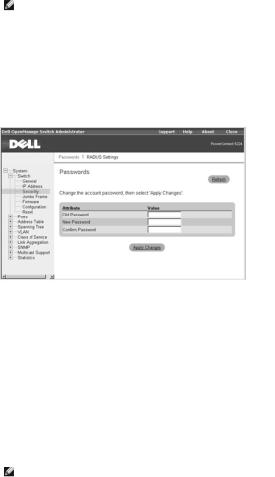
Passwords
You should change the default passwords to be sure that your system is secure:
NOTE: The default user names are admin and guest, and the corresponding passwords are admin and guest. If you log in as guest (Normal Exec level), you can only view page information and change the guest password. If you log in as admin (Privileged Exec level), you can apply changes on all pages.
•Old Password — Type your current password.
•New Password — Type the new password. Passwords are limited to eight characters and are case sensitive.
•Confirm Password — Type the new password a second time to verify that you have typed it correctly.
The password entered is encrypted on the screen and is displayed as a sequence of asterisks (*).
To save any changes you make in this page, click Apply Changes. If you don't want to save the changes, click Refresh.
CLI Commands
The following table summarizes the equivalent CLI commands for items in the Switch/Security/Passwords page.
Command |
Usage |
|
|
enable password [level |
Use this command to control access to the Privileged Exec level from the Normal |
level] {0 | 7} password |
Exec level. For the {0 | 7} parameter, 0 means plain password and 7 means |
|
encrypted password. The Privileged Exec level is 15 and the default password is |
|
super. |
|
|
username name {access- |
Use this command to configure user name authentication at login. Use the no |
level level | nopassword | |
form command to remove a user name. The device has two predefined privilege |
password {0 | 7} |
levels: 0: Normal Exec and 15: Privileged Exec. The default user names are |
password} |
admin for the Privileged Exec level, and guest for the Normal Exec level. |
|
|
NOTE: Only the CLI allows user names to be created and deleted.
Example
Console(config)#enable password level 15 0 admin
Console(config)#username bob access-level 15
Console(config)#username bob password smith
Console(config)#
RADIUS Settings
Remote Authentication Dial-in User Service (RADIUS) is a system that uses a central server running RADIUS software to control access to RADIUS-aware switches on the network. A RADIUS server can be used to create a database of multiple user name/password pairs with associated privilege levels for each user or group that require management access to a switch using the console port, Telnet, or Internet.
When you are setting up privilege levels on the RADIUS server, level 0 allows Normal Exec access to the switch, and level 15 allows Privileged Exec access.
The RADIUS Settings page contains the following editable fields:
•Authentication — Select the authentication, or authentication sequence, required:
¡Radius — A RADIUS server authenticates the user.
¡Local — The switch authenticates the user.
¡Radius, Local — A RADIUS server attempts to authenticate the user first, and then the switch attempts to authenticate the user.

¡ Local, Radius — The switch attempts to authenticate the user first, and then a RADIUS server attempts to authenticate the user.
•Server IP Address — Identifies the IP address of the RADIUS server.
•Server Port Number — Identifies the User Datagram Protocol (UDP) port number used by the RADIUS server.
•Secret Text String — Specifies the text string that is shared between the switch and the RADIUS server.
•Number of Server Transmits — Specifies the number of request transmits to the RADIUS server before failure.
•Timeout for a reply (sec)— Specifies the number of seconds the switch waits for a reply from the RADIUS server before it resends the request.
NOTE: The local switch user database must be set up through the CLI by manually entering user names and passwords.
To save any changes you make in this page, click Apply Changes. If you don't want to save the changes, click Refresh.
CLI Commands
The following table summarizes the equivalent CLI commands for items in the Switch/Security/RADIUS Settings page.
Command |
Usage |
|
|
authentication login {radius | local | |
Defines the login authentication method and precedence. |
radius local | local radius} |
|
|
|
radius-server host host_ip_address |
Specifies the RADIUS server IP address. |
radius-server port port_number |
Sets the RADIUS server UDP port number. |
|
|
radius-server key key_string |
Sets the RADIUS encryption key (up to 20 characters). |
|
|
radius-server retransmit |
Sets the number of times the switch attempts to authenticate |
number_of_retries |
logon access through the RADIUS server. (The range is 1–30.) |
|
|
radius-server timeout |
Sets the number of seconds the switch waits for a reply before |
number_of_seconds |
resending a request. (The range is 1–65535.) |
|
|
Example
Console(config)#authentication login radius
Console(config)#radius-server host 192.168.1.25
Console(config)#radius-server port 181
Console(config)#radius-server key solvent
Console(config)#radius-server retransmit 5
Console(config)#radius-server timeout 10
Console(config)#
Jumbo Frame
From the Jumbo Frame page, you can enable and disable jumbo frame support on the switch.
The switch provides more efficient large sequential data transfers by supporting jumbo frames up to 9000 bytes. Compared to standard Ethernet frames that run only up to 1500 bytes, using jumbo frames significantly reduces the per-packet overhead required to process protocol encapsulation fields.
To use jumbo frames, both the source and destination end nodes (such as a computer or server) must support jumbo frames. In addition, when the connection is operating at full duplex, all switches in the network between the two end nodes must be able to accept the extended frame size. For half-duplex connections, all devices in the collision domain must support jumbo frames.
To enable jumbo frame support on the switch, set the Jumbo Frame Support Status to Enabled.
NOTICE: Enabling jumbo frames on the switch limits the maximum threshold for broadcast storm control to 64 packets per second.

To save any changes you make in this page, click Apply Changes. If you don't want to save the changes, click Refresh.
CLI Commands
The following table summarizes the equivalent CLI command for items in the Switch/Jumbo Frame page.
Command |
Usage |
|
|
jumbo |
Use this command to enable jumbo frames to be forwarded through the switch. Use the no |
frame |
form to disable jumbo frames. |
|
|
Example
Console(config)#jumbo frame
Console(config)#
Firmware Upgrade
From the Firmware page, you can configure the system to download a new version of the management software. The switch can contain two software code files, one of which is set as the Start-Up file. This allows you to try a new version of the software without overwriting the previous version.
NOTE: The switch is shipped with one software code file installed (the filename is similar to PC5224_v1.00.00.00), which is set as the startup file.
The Firmware page contains the following fields:
• Current Operation Code Version
It also contains the following editable fields:
•TFTP Server IP Address — Specifies the server from which the system must retrieve the new version of the software.
•Source File Name — Specifies the path and name of the software file to download.
•Destination File Name — Specifies the file to be replaced.
•Remove Operation Code Image File — Deletes a software file from the switch.
•Start-Up Operation Code File Name — Indicates which Operation Code file you want to run. Select the filename from the drop-down menu.
Uploading Operation Code to a Server
1.In the Transfer Operation Code Image File to Server field, enter the IP address of the Trivial File Transfer Protocol (TFTP) server in the TFTP Server IP Address field.
2.In the Source File Name field, select the file to upload from the dropdown menu.
3.In the Destination File Name field, type a name for the file.
4.Click Transfer to Server.
Downloading Operation Code from a Server
1.In the Transfer Operation Code Image File from Server field, enter the IP address of the TFTP server in the TFTP Server IP Address field.
2.In the Source File Name field, type the filename of the software code file to download.
3.For the Destination File Name, select a filename from the drop-down menu to replace an existing file, or specify a new filename (with no more than 32 characters). Filenames are case sensitive and cannot contain spaces. The switch can contain only two software code files. You cannot download a third file; you must first replace an existing file or remove a file.
4.Click Transfer from Server.
Deleting an Operation Code File from the Switch
1.In the Remove Operation Code Image File field, select the file to delete from the drop-down menu.
2.Click Remove File.

Selecting the Operation Code Start-up File
1.In the Start-Up Operation Code Image File field, select the start-up code file from the drop-down menu.
2.Click Apply Changes.
The following table summarizes the equivalent CLI commands for items in the Switch/Firmware page.
Command |
Usage |
|
|
copy tftp file |
Downloads a code image to the switch's flash memory from a |
|
TFTP server |
|
|
boot system {boot-rom | config | opcode}: |
Specifies the file or image used to start up the system |
filename |
|
|
|
dir [boot-rom | config | opcode [:filename]] |
Displays a list of files in flash memory |
|
|
NOTE: You cannot upload and download Boot-ROM files to a TFTP server using the CLI. You must use a direct terminal connection to the switch's console port and press <Ctrl><f> after the diagnostic test results. See "Downloading Firmware Through the Console Port."
Example
Console#copy tftp file
TFTP server ip address: 10.1.0.45
Choose file type:
1. config: 2. opcode: <1-2>: 2
Source file name: runtime
Destination file name: 0126.bix
/
Console#
Configuration
From the Configuration page you can save and restore switch configuration settings.
NOTE: The switch is shipped with one default configuration file (Factory_Default_
Config.cfg) installed, which is set as the startup file. This file cannot be removed from the system.
The Configuration page contains the following editable fields:
•Transfer Configuration to Server — Copies a switch configuration file to a TFTP server.
•Transfer Configuration from Server — Copies a switch configuration file from a TFTP server.
•Remove Configuration File — Deletes a configuration file from the switch (selected from the drop-down menu).
•Start-Up Configuration File — Selects the configuration file to be used after a system start-up (selected from the drop-down menu).
•Copy Running Config to File — Saves the current session configuration settings. Specifies a new filename or the name of an existing file to be replaced.
NOTICE: For configuration changes to persist beyond the current session, you must save the running-config file from this page, or use the CLI command copy running-config startup-config.
Transferring a Configuration File to a Server
1. In the Transfer Configuration File to Server field, enter the IP address of the TFTP server in the TFTP Server IP Address field.

2.In the Source File Name field, select the configuration file to upload from the drop-down menu.
3.For the Destination File Name, type a filename to identify the configuration file on the TFTP server.
4.Click Transfer to Server.
Transferring a Configuration File from a Server
1.Under Transfer Configuration File from Server, enter the IP address of the TFTP server in the TFTP Server IP Address field.
2.In the Source File Name field, type the filename of the configuration file to download.
3.In the Destination File Name field, select a configuration file to replace from the drop-down menu, or specify a new filename (with no more than 32 characters). Filenames are case sensitive and cannot contain spaces. The switch can contain any number of configuration files, limited only by available flash memory space. You can use the dir command in the CLI to check the available flash memory space.
4.Click Transfer from Server.
NOTE: The CLI also allows you to copy files within the switch and replace a running configuration file without performing a reset.
Deleting a Configuration File from the Switch
1.In the Remove Configuration File field, select the file to delete from the drop-down menu.
2.Click Remove File.
Selecting the Start-up Configuration File
1.In the Start-Up Configuration File field, select the start-up configuration file from the drop-down menu.
2.Click Apply Changes.
Copying the Running Configuration to a File
1.In the Copy Running Config to File field, specify a filename for the configuration file (with no more than 32 characters). If the filename already exists, it replaces the file. The filename cannot be the same as the factory default configuration file, Factory_Default_Config.cfg.
2.Click Copy to File.
CLI Commands
The following table summarizes the equivalent CLI commands for items in the Switch/Configuration web page.
Command |
Usage |
|
|
copy file {file | running-config | startup- |
Uploads/downloads a configuration file to/from the switch's flash |
config | tftp} |
memory to a TFTP server |
boot system {boot-rom| config | |
Specifies the file or image used to start up the system |
opcode}: filename |
|
|
|
Example
Console#copy tftp startup-config
TFTP server ip address: 10.1.0.99
Source configuration file name: startup.01
Startup configuration file name [startup]:
/
Console#
Reset
Click Reset to reboot the switch. When prompted, confirm that you want to reset the switch.
CLI Commands
The following table summarizes the equivalent CLI command for items in the Switch/Reset page.
Command |
Usage |
|
|
reload |
Restarts the system |
Example
Console#reload
System will be restarted, continue <y/n>? y
Console#
Ports
The Port Manager contains links to the following options:
•Port Configuration
•Trunk Configuration
•Broadcast Control
•Port Mirroring
Port Configuration
On the Port Configuration page, you can view and edit port parameters. For each port number listed in the Port column, you can change the following parameters listed by column name on the screen:
•Name/Type — Allows a user-defined label for the port and indicates the type of port:
¡1000Base-TX — 10/100/1000Base-T RJ-45 port
¡1000Base-SFP — gigabit SFP transceiver port
•Admin/Oper — Allows the network administrator to manually disable a port and indicates the status of the link: up or down.
•Speed/Duplex Mode — Allows the manual selection of port speed and duplex mode and indicates the current port speed and mode.

•Flow Control — Allows automatic or manual selection of support for flow control and indicates the type of flow control currently in use.
•Autonegotiation/Port Capabilities — Allows autonegotiation to be enabled/disabled and indicates the capabilities of the port that are advertised during autonegotiation:
¡10h — Supports 10-megabits per second (Mbps) half duplex.
¡10f — Supports 10-Mbps full duplex.
¡100h — Supports 100-Mbps half duplex.
¡100f — Supports 100-Mbps full duplex.
¡1000h — Supports 1000-Mbps half duplex.
¡1000f — Supports 1000-Mbps full duplex.
¡Sym — Supports symmetric operation of full-duplex flow control. The port can transmit and receive pause frames for flow control (gigabit ports only).
¡FC — Supports full-duplex flow control.
•Trunk — Indicates whether a port is a member of an aggregated link or trunk.
NOTICE: If autonegotiation is disabled for an RJ-45 port, the auto- MDI/MDI-X pin signal configuration is also disabled.
CLI Commands
The following table summarizes the equivalent CLI commands for items in the Ports/Port Configuration page.
Command |
Usage |
|
|
interface ethernet unit/port |
Configures an Ethernet port interface and enters interface |
|
configuration mode. |
|
|
shutdown |
Disables an interface. |
|
To restart a disabled interface, use the no form command. |
|
|
description string |
Adds a description to an interface. |
|
|
speed-duplex {1000full | 100full | |
Configures the speed and duplex mode of a given interface when |
100half | 10full | 10half} |
autonegotiation is disabled. |
negotiation |
Enables autonegotiation for a given interface. |
|
Use the no form command to disable autonegotiation. |
|
|
capabilities {1000full | 100full | |
Advertises the port capabilities of a given interface during |
100half | 10full | 10half | flowcontrol | |
autonegotiation. |
symmetric} |
|
|
Use the no form with parameters command to remove an advertised |
|
capability, or the no form without parameters command to restore |
|
the default values. |
|
|
flowcontrol |
Enables flow control. |
|
Use the no form command to disable flow control. |
|
|
show interfaces status ethernet |
Displays status for enabled interfaces. |
unit/port |
|
show interfaces switchport [ethernet |
Displays the configuration for a port. |
unit/port] |
|
|
|
NOTICE: Flow control only works for ports connected to the same internal switch chip (ports 1 to 12 and ports 13 to 24). Cross-chip flow control does not work.
Example
Console(config)#interface ethernet 1/5
 Loading...