


Dell™ PowerVault™ 124T LTO3-060 Autoloader User's Guide
Introduction
Installing the Autoloader
Operating the Autoloader
Remote Management Unit
Front Panel Administration
Diagnostics
Troubleshooting
Technical Specifications
Getting Help
Notes, Notices, and Cautions
NOTE: A NOTE indicates important information that helps you make better use of your system.
NOTICE: A NOTICE indicates either potential damage to hardware or loss of data and tells you how to avoid the problem.
CAUTION: A CAUTION indicates a potential for property damage, personal injury, or death.
Information in this document is subject to change without notice. © 2005-2007 Dell Inc. All rights reserved.
Reproduction in any manner whatsoever without the written permission of Dell Inc. is strictly forbidden.
Trademarks used in this text: Dell, the DELL logo, PowerVault, Dimension, Inspiron, OptiPlex, Latitude, Dell Precision, PowerApp, PowerEdge, PowerConnect, and
DellNet are trademarks of Dell Inc.; Microsoft, Windows, Windows NT, and Windows Server are registered trademarks of Microsoft Corporation. DLTtape is a registered trademark of Quantum Corporation. Adobe is either a registered trademark or trademark of Adobe Systems Incorporated in the United States and/or other countries. RedHat is a registered trademark of Red Hat, Inc. Mozilla and Firefox are trademarks of Mozilla.
Other trademarks and trade names may be used in this document to refer to either the entities claiming the marks and names or their products. Dell Inc. disclaims any proprietary interest in trademarks and trade names other than its own.
Initial release: 15 Jun 2005
Revised: September 2007

Back to Contents Page
Front Panel Administration: Dell™ PowerVault™ 124T LTO3-060 Autoloader User's
Guide
Configuring the Autoloader |
SCSI Barcode Length |
Setting the SCSI ID |
Setting Security |
Setting Ethernet |
Setting Magazines |
Setting the Time |
Setting Passwords |
Barcode Reader |
|
When you first power on the Dell PowerVault 124T LTO3-060 autoloader, it automatically runs a Power-On Self-Test (POST). During the POST, the left (green) LED flashes. After the POST, the left (green) and right (amber) LED flash alternately back and forth. Do one of the following:
• If the autoloader powers on successfully, continue configuring the autoloader (see "Configuring the Autoloader").
NOTE: The front panel requires a six-digit password to change the configuration (see "Setting Passwords"). The LCD front panel default password for the Administrator is 000000. The default password for the Operator is 111111.
•If the autoloader does not power on successfully, check the following:
¡Power switch is on.
¡Power cable is inserted correctly.
¡SCSI bus is terminated.
¡SCSI cable is connected to the autoloader and host computer.
¡No error code appears on the autoloader LCD.
If you cannot resolve the problem yourself, contact your service representative or go to the Dell Support website at support.dell.com.
When you first power on the autoloader, the setting for the Internet Protocol (IP) address is static with the address 192.168.20.128. If you want to use Dynamic Host Configuration Protocol (DHCP) to change the IP address, see "Setting the IP Address." To determine the IP address when using DHCP, view the Ethernet status information (see "Viewing Ethernet Information").
Configuring the Autoloader
To configure the autoloader, start with the main menu on the front panel. If the main menu is not already visible on the LCD, press Enter.
When you first power on the autoloader, the default is set with no password protection. However, after you set the security option, all the configuration functionality is password-protected. You need an administrator-level password to configure the autoloader.
The front panel menu has the following options:

To configure the Dell PowerVault 124T LTO3-060 autoloader, you must verify the setup of the following:
•SCSI ID(s). For the autoloader, there is a single SCSI ID.
•Magazine(s).
•Ethernet IP address (if you are not using DHCP).
•SNMP server IP address—only if SNMP is being used.
•Time server IP address (or the time zone, date, and time, if configuring manually)—only if a time server is being used.
•Control mode.
•Security option.
Setting the SCSI ID
Each SCSI device attached to a server or workstation must have a unique SCSI ID. For the PowerVault 124T autoloader, you need one SCSI ID.
To set the SCSI ID:
1.If the main menu is not already visible, press Enter.
2.On the main menu, scroll to Configuration and press Enter.
3.On the Configuration submenu, scroll to SCSI ID and press Enter.
4.Scroll to the number you want to set as the autoloader's SCSI ID, then press Enter. Cycle Power new SCSI ID appears on the LCD.
5.Press and hold the power button on the front panel until System Shutdown wait 60 sec appears on the LCD. Power Off appears on the LCD, then the autoloader shuts off.
6.Press the power button again to power on the autoloader. The new SCSI ID is now in effect.
Setting Ethernet
Ethernet is the method used by the autoloader to access a network. With an Ethernet connection, you can remotely access the autoloader over the network. To use the Ethernet connection, you must define the following:
•A dynamic or static IP address for the autoloader (required)
•A subnet mask (required for static IP)

•An IP gateway (optional)
•A Simple Network Management Protocol (SNMP) server (optional)
•A time server, or set the time and time zone manually (optional)
Setting the IP Address
An IP address is the address of any device attached to a network. Each device must have a unique IP address. IP addresses are written as four sets of numbers separated by periods ranging from 0.0.0.0 up to and including 255.255.255.255.
IP addresses are either permanent or dynamically assigned. A permanent, or static, address remains the same each time the device connects to the network. A dynamic address may change each time the device connects to the network server using Dynamic Host Configuration Protocol (DHCP).
To set a dynamic IP address:
1.From the main menu, scroll to Configuration, and then press Enter.
2.From the Configuration menu, scroll to Ethernet, and then press Enter.
3.From the Ethernet submenu, scroll to Set IP, and then press Enter.
4.Scroll to DHCP, and then press Enter.
To set a static IP address:
1.From the main menu, scroll to Configuration, and then press Enter.
2.From the Configuration menu, scroll to Ethernet, and then press Enter.
3.From the Ethernet submenu, scroll to Set IP, and then press Enter.
4.Scroll to Static IP, and then press Enter. The cursor automatically appears at the first digit.
5.At each position of the IP address, use the up and down arrows to change the value of each digit. Press Enter to advance the cursor to the next digit.
When you have advanced through all of the digits of the IP address, the autoloader displays Enter to save.
NOTE: If you make a mistake, press Escape to backspace to the digit you want to change.
6.Press Enter. The Configuration submenu appears and the static IP is now in effect. You do not need to reboot the autoloader.
7.Press Escape or Enter to return to the Ethernet submenu.
Setting the Subnet Mask
Creating a subnet mask is a method of splitting IP networks into a series of subgroups, or subnets, to improve performance or security.
To set a subnet mask:
1.From the main menu, scroll to Configuration, and then press Enter.
2.From the Configuration menu, scroll to Ethernet, and then press Enter.
3.From the Ethernet submenu, scroll to Set Subnet Mask, and then press Enter.
4.At each position of the Subnet Mask address, use the up and down arrows to change the value of each digit. Press Enter to advance the cursor to the next digit.
When you have advanced through all of the digits of the subnet mask address, the autoloader displays Enter to save.
NOTE: If you make a mistake, press Escape to backspace to the digit you want to change.
5.Press Enter. New Subnet Mask xxx.xxx.xxx.xxx appears on the LCD. You do not need to reboot the autoloader.
6.Press Escape or Enter to return to the Ethernet submenu.
Setting an IP Gateway
1.From the main menu, scroll to Configuration, and then press Enter.
2.From the Configuration menu, scroll to Ethernet, and then press Enter.
3.From the Ethernet submenu, scroll to Set Gateway, and then press Enter. The cursor automatically appears at the first digit.
4.At each position of the gateway address, use the up and down arrows to change the value of each digit. Press Enter to advance the cursor to the next digit.
When you have advanced through all of the digits of the gateway address, the autoloader displays Enter to save.

NOTE: If you make a mistake, press Escape to backspace to the digit you want to change.
5.Press Enter. New Gateway is xxx.xxx.xxx.xxx appears on the LCD. You do not need to reboot the autoloader.
6.Press Escape or Enter to return to the Ethernet submenu.
Setting the SNMP Server
An SNMP server monitors a network by processing reporting activity in each network device (hub, router, bridge, and so on). The server uses this information to define what is obtainable from each device and what can be controlled (turned off, on, and so on).
NOTE: The PV124T SNMP agent supports only the MIB-II variable group. The MIB provides power-on notification commonly referred to as the "cold start trap" which is sent to the SNMP host (if configured). Embedded webserver user interface is supported for configuring the SNMP server. However, extended SNMP functions such as availability of tape information through SNMP, SNMP traps for tape events, availability of global tape status information through SNMP, availability of information through SNMP to classify the loader as a tape device, etc. are not supported.
To set an SNMP server:
1.From the main menu, scroll to Configuration, and then press Enter.
2.From the Configuration menu, scroll to Ethernet, and then press Enter.
3.From the Ethernet submenu, scroll to Set SNMP Server, and then press Enter. The cursor automatically appears at the first digit.
4.At each position of the SNMP server address, use the up and down arrows to change the value of each digit. Press Enter to advance the cursor to the next digit.
When you have advanced through all of the digits of the SNMP server address, the autoloader displays Enter to save.
NOTE: If you make a mistake, press Escape to backspace to the digit you want to change.
5.Press Enter. New SNMP Server xxx.xxx.xxx.xxx appears on the LCD. You do not need to reboot the autoloader.
6.Press Escape or Enter to return to the Ethernet submenu.
Setting the Time
The system time is displayed by the RMU and it is used internally when logging events and errors. The system time is either regular time or power-on time. Regular time is Month/Date/Year Time, such as Nov/21/2004 19:28. Power-on time is Power On Cycles (POC)/Power On Hours (POH). For example, POC: 00121, POH: 00002:07:45 where POC is the number of times the system has booted since it was manufactured, and POH is the number of hours, minutes, and seconds since the last system boot. If regular time is known, it will be used, otherwise power-on time is used.
The PowerVault 124T autoloader must be reset after each power up. The time can be reset automatically if a time server is configured (see "Setting the Time Server").
Setting the Time Server
If you locate a time server that is compatible with Simple Network Time Protocol (SNTP), you can connect the autoloader to a server that will supply the correct date and time. The autoloader uses this information to time stamp information in its memory.
To set a time server:
1.From the main menu, scroll to Configuration, and then press Enter.
2.From the Configuration menu, scroll to Ethernet, and then press Enter.
3.From the Ethernet submenu, scroll to Set Time Server, and then press Enter. The cursor automatically appears at the first digit.
4.At each position of the time server address, use the up and down arrows to change the value of each digit. Press Enter to advance the cursor to the next digit.
When you have advanced through all of the digits of the time server address, the autoloader displays Enter to save.
NOTE: If you make a mistake, press Escape to backspace to the digit you want to change.
5.Press Enter. New Time Server xxx.xxx.xxx.xxx appears on the LCD. You do not need to reboot the autoloader.
6.Press Escape or Enter to return to the Ethernet submenu.
To set the time zone:
1.From the main menu, scroll to Configuration, and then press Enter.
2.From the Configuration menu, scroll to Time, and then press Enter.
3.From the Time submenu, scroll to Set Timezone, and then press Enter. The Time Zone screen appears, allowing you to set the hours. The cursor

automatically appears at the first digit.
4.Scroll to set the number of hours difference between your local time and Greenwich Mean Time (GMT).
5.Scroll to set the number of minutes difference between your local time and GMT, then press Enter. The new time zone is set.
6.Press Escape or Enter as necessary to return to the main menu.
To set the date and time:
1.From the main menu, scroll to Configuration, and then press Enter.
2.From the Configuration menu, scroll to Time, and then press Enter.
3.From the Time submenu, scroll to Set Date/Time, and then press Enter. The Date/Time screen appears, allowing you to set the date and time. The cursor automatically appears at the first digit.
4.The first four digits represent the current year. At each position of the year, use the up and down arrows to change the value of each digit. Press Enter to advance the cursor to the next digit.
5.The next two digits represent the current month. At each position of the month, use the up and down arrows to change the value of each digit. Press Enter to advance the cursor to the next digit.
6.The next two digits represent the current day. At each position of the day, use the up and down arrows to change the value of each digit. Press Enter to advance the cursor to the next digit.
7.The next two digits represent the current hour. At each position of the hour, use the up and down arrows to change the value of each digit. Press
Enter.
8.The last two digits represent the current minute. At each position of the minute, use the up and down arrows to change the value of each digit. Press Enter to advance the cursor to the next digit.
9.Press Enter to save.
10.Press Escape as necessary to return to the main menu.
Barcode Reader
You can enable or disable the Barcode Reader from the Operator Control Panel (OCP). Disabling the barcode reader prevents the barcode reader from attempting to read label information. If barcode labels are not being used, disabling the barcode reader will reduce initialization time.
Either a power cycle (through the front panel button) or an Autoloader Reset (through the Autoloader Reset command found on the Error Logs and Diagnostics page of the Web interface) is required for the change to take effect.
To change the Barcode Reader setting:
1.From the main menu, scroll to Configuration, and then press Enter.
2.From the Configuration menu, scroll to Barcode Reader and press Enter.
3.A checkmark will be present before either Barcode Enabled or Barcode Disabled to indicate the current setting. Scroll to the desired setting and press
Enter.
4.Press Esc as necessary to return to the main menu.
5.Power cycle the autoloader as requested.
SCSI Barcode Length
SCSI Barcode Length sets the maximum number of barcode characters that will be returned in the SCSI Read Element Data. The display of barcode information on the Web interface and Operator Control Panel (OCP) are unaffected by this setting.
Setting the SCSI Barcode Length to 0 disables truncation of the barcode and the full barcode will be returned in the SCSI Read Element Data.
This setting is particularly useful if you have a pool of media previously catalogued by another device that has a limitation on the number of barcode characters that can be read (typically 6 or 9). Adjusting the PV124T setting to match the previous hardware prevents the user from having to re-catalog all barcode labeled media previously used in the other device.
To change the SCSI Barcode setting:
1.From the main menu, scroll to Configuration, and then press Enter.
2.From the Configuration menu, scroll to SCSI Barcode and press Enter.
3.Scroll to the desired setting (from 0 to 15) and press Enter.
4.Press Esc as necessary to return to the main menu. The autoloader does not need to be reset when making this change.

Setting Magazines
In some cases, autoloader owners were being charged Independent Software Vendor (ISV) licensing fees for two-magazine autoloaders although only one magazine was configured. This occurred because the ISV software was registering the autoloader as a two-magazine device, regardless of the number of magazines configured. You have the ability to set the number of magazines in the autoloader. The default setting is Left.
To set the number of magazines:
1.From the main menu, scroll to Configuration, and then press Enter.
2.From the Configuration menu, scroll to Magazines, and then press Enter.
3.From the Magazines menu, select either Right, Left, or Both to indicate the magazines installed in the autoloader.
NOTE: The default setting must be reconfigured if the optional right magazine is installed. Host backup software may also require a configuration change to support the additional media locations.
Setting Security
You can add security to the front panel by password-protecting the autoloader's functionality. The security setting only protects the front panel functionality. The default setting is Off, meaning that no password is required. However, you can enable the security option so that users must enter a password to access functionality.
Security Option
When you first power on the autoloader, the security option is set to Off. Use the following procedure to enable the security option. You must have an administrator-level password to set passwords.
To set the security option:
1.From the main menu, scroll to Configuration, and then press Enter.
2.From the Configuration menu, scroll to Security. If a check mark appears before the word, the security option is On. If no check mark appears, the security option is Off.
3.Press Enter. If you are not logged in as Administrator, press Enter again to log in.
4.To change the option, press Enter. For example, if the security option was set to On, it is now set to Off, and no check mark appears.
Setting Passwords
Many operations on the autoloader are password-protected to ensure data integrity. You can set passwords to administrator level and to operator level. Operator-level users have access to the Commands and Status menus. Administrator-level users have access to all functionality.
To set a password:
1.From the main menu, scroll to Configuration, and then press Enter.
2.From the Configuration menu, scroll to Set Password, and then press Enter.
3.To set a password to the operator level, scroll to Operator. To set a password to the administrator level, scroll to Administrator.
4.Press Enter. If you are not logged in as Administrator, press Enter again to log in.
5.In the text box, scroll to the first character of the password. The cursor automatically appears at the first number of the password.
6.At each position of the password, use the up and down arrows to change the value of each number. Press Enter to advance the cursor to the next number.
NOTE: If you make a mistake, press Escape to backspace to the digit you want to change.
7.When you have entered six numbers, the autoloader displays Submit Password.
8.Press Enter to submit the password. Password Successfully changed appears on the LCD.
9.Press Enter. The Operator and Administrator options reappear. You can either enter another password, or press Escape or Enter as necessary to return to the main menu.
Getting Lost Passwords
If you forget the administrator-level password, you cannot access the autoloader's functionality to enter a new password. In this case, you must call support.dell.com. When you call, have the autoloader connected to the Ethernet and open the RMU.
NOTE: You can reset front panel passwords to the factory defaults from the RMU. However, if the RMU passwords are lost, you must contact support.dell.com. If you must contact support.dell.com, be at the host computer with the RMU on line. From the main screen,

click Configuration. The Enter Network Password or User name screen displays. The customer support representatives will need the number surrounded by asterisks to locate and reset your password. This is your "realm number."
Back to Contents Page

Back to Contents Page
Diagnostics: Dell™ PowerVault™ 124T LTO3-060 Autoloader User's Guide
 Diagnostic Tests from the Front Panel
 Remote Management Unit Diagnostic Tests
Diagnostic Tests from the Front Panel
Diagnostic tests allow you to calibrate parts of the autoloader, check the condition of parts, or test the autoloader's functionality. From the front panel, you can perform all of the diagnostic tests. Because certain tests require you to manually insert a minimum of two cartridges, you can perform only some of the diagnostic tests using the Remote Management Unit (RMU). See "Remote Management Unit Diagnostic Tests".
NOTE: The RMU allows you to request all diagnostic tests, but any tests that require a cartridge to be inserted will time-out unless someone manually inserts the cartridge at the appropriate time.
Setting the Security
When you enable the security function, the diagnostic tests are password protected to ensure data integrity. To access any of the diagnostic tests, you must first enter an Administrator password. If you do not enter the password, you will be prompted to enter the password when you attempt to perform a diagnostic test.
You can also enter passwords from the Commands menu as follows::
1.From any menu, click the Commands heading. The Commands screen displays.
2.On the Commands submenu, scroll to Enter Password, and then press Enter.
3.On the Enter Password submenu, scroll to Administrator, and then press Enter.
4.In the text box, scroll to the first number of the password, and then press Enter.
5.Repeat step 4 to enter the remaining numbers of your password.
NOTE: Press Escape to backspace to a previous text box, if necessary.
When you have finished entering your password, Submit Password appears on the LCD below the asterisks.
6. Press Enter to submit your password. The display returns to the Enter Password submenu.
Stopping a Diagnostic Test
At times, you may need to stop a diagnostic test while it is in progress. To stop a diagnostic test while it is running, use the End Curr. Test function. When you select End Curr. Test, any picker or magazine functions complete, and then the diagnostic test stops.
To end a test from the front panel:
1.While the diagnostic test you wish to stop is running, press Escape. The Diagnostics submenu displays.
2.On the submenu, scroll to End Curr. Test, and then press Enter. User Abort displays.
3.Press Enter to return to the Diagnostics submenu. Refer to the RMU for any test results.
To stop a test from the RMU:
1.Select the Stop Test button in the Diagnostics test section of the Error Logs and Diagnostics page.
2.Select View Status to see the results of the command. Test Stopped displays along with any test results.
Front Panel Diagnostic Tests
You can perform the following diagnostic tests using the front panel:
•Picker Test
•Magazine Test
•Inventory Test
•Random Moves
To perform any of the front panel diagnostic tests:
1. From any menu, click the Diagnostics heading. The Diagnostics screen displays.

2.Scroll to the test you want to run and press Enter.
If you are already logged in as Administrator, the test begins executing immediately. The message Running Test appears while the test is running.
NOTE: Each test takes from 30 seconds to several minutes to complete. To stop the test prematurely, see "Stopping a Diagnostic Test."
3.If you are not logged in, you will be asked to enter the Administrator password. Do the following:
¡From the front panel, enter the administrator password by using the Up and Down scroll arrows to select each digit, and then press Enter to move to the next digit. To move to the previous digit, press Escape. When you have entered the entire six digit password, you will be asked to press Enter one more time to submit the password. If the password is incorrect, you will be asked to re-enter it using the same procedure. Otherwise, you will be returned to the Diagnostics menu. Press Enter to run the desired test.
Running Test appears while the test is in progress. To stop the test prematurely, see "Stopping a Diagnostic Test."
4.If the test is successful, press Enter to return to the Diagnostic test menu. For detailed results of a test, use the RMU to retrieve the diagnostic test status (see "Running Diagnostic Tests").
RMU Diagnostic Tests
Because some of the diagnostic tests require you to insert a cartridge into the autoloader, you cannot perform these tests from a remote location. You can perform the following diagnostic tests from the RMU:
•Loader - Picker Test
•Loader - Magazine Test
•Loader - Inventory Test
•Random Moves
NOTE: The RMU allows you to request all diagnostic tests, but any tests that require a cartridge to be inserted will time-out unless someone manually inserts the cartridge at the appropriate time.
Diagnostics Using the RMU
Many tests can be run using the RMU. To perform the RMU diagnostic tests:
1.Open a Web browser and connect to the autoloader. The RMU main menu appears.
2.Click the Error Logs and Diagnostics heading. A login window appears.
3.Type an Administrator user name and a password, and then click Enter. The Diagnostics submenu appears.
4.Select the test you wish to perform from the Diagnostics drop-down menu, and then click submit.
The selected diagnostic test runs. While the test is running, you can view the status of the test. To view the status, from the View Diagnostic Test Progress section, click View Status.
Back to Contents Page
Back to Contents Page
Getting Help: Dell™ PowerVault™ 124T LTO3-060 Autoloader User's Guide
 Technical Assistance
 Dell Enterprise Training and Certification
 Problems With Your Order
 Product Information
 Returning Items for Warranty Repair or Credit
 Before You Call
Technical Assistance
If you need assistance with a technical problem, perform the following steps:
1.Complete the procedures in "Before Contacting Customer Support".
2.Run the system diagnostics and record any information provided.
3.Use Dell's extensive suite of online services available at Dell Support at support.dell.com for help with installation and troubleshooting procedures.
For more information, see "Online Services."
4.If the preceding steps have not resolved the problem, call Dell for technical assistance.
NOTE: Call technical support from a phone near or at the system so that technical support can assist you with any necessary procedures.
NOTE: Dell's Express Service Code system may not be available in all countries.
When prompted by Dell's automated telephone system, enter your Express Service Code to route the call directly to the proper support personnel. If you do not have an Express Service Code, open the Dell Accessories folder, double-click the "Express Service Code" icon, and follow the directions.
For instructions on using the technical support service, see "Technical Support Service" and "Before You Call."
NOTE: Some of the following services are not always available in all locations outside the continental U.S. Call your local Dell representative for information on availability.
Online Services
You can access Dell Support at support.dell.com. Select your region on the WELCOME TO DELL SUPPORT page, and fill in the requested details to access help tools and information.
You can contact Dell electronically using the following addresses:
•World Wide Web
www.dell.com/
www.dell.com/ap (Asian/Pacific countries only)
www.dell.com/jp (Japan only)
www.euro.dell.com (Europe only)
www.dell.com/la (Latin American countries)
www.dell.ca (Canada only)
•Anonymous file transfer protocol (FTP)
ftp.dell.com/
Log in as user:anonymous, and use your e-mail address as your password.
• Electronic Support Service
support@us.dell.com
apsupport@dell.com (Asian/Pacific countries only)
support.jp.dell.com (Japan only)
support.euro.dell.com (Europe only)
• Electronic Quote Service
sales@dell.com
apmarketing@dell.com (Asian/Pacific countries only)
sales_canada@dell.com (Canada only)
• Electronic Information Service
info@dell.com
AutoTech Service
Dell's automated technical support service — AutoTech — provides recorded answers to the questions most frequently asked by Dell customers about their portable and desktop computer systems.
When you call AutoTech, use your touch-tone telephone to select the subjects that correspond to your questions.
The AutoTech service is available 24 hours a day, 7 days a week. You can also access this service through the technical support service. See the contact information for your region.

Automated Order-Status Service
To check on the status of any Dell™ products that you have ordered, you can go to support.dell.com, or you can call the automated order-status service. A recording prompts you for the information needed to locate and report on your order. See the contact information for your region.
Technical Support Service
Dell's technical support service is available 24 hours a day, 7 days a week, to answer your questions about Dell hardware. Our technical support staff use computer-based diagnostics to provide fast, accurate answers.
To contact Dell's technical support service, see "Before You Call" and then see the contact information for your region.
Dell Enterprise Training and Certification
Dell Enterprise Training and Certification is available; see www.dell.com/training for more information. This service may not be offered in all locations.
Problems With Your Order
If you have a problem with your order, such as missing parts, wrong parts, or incorrect billing, contact Dell for customer assistance. Have your invoice or packing slip available when you call. See the contact information for your region.
Product Information
If you need information about additional products available from Dell, or if you would like to place an order, visit the Dell website at www.dell.com. For the telephone number to call to speak to a sales specialist, see the contact information for your region.
Returning Items for Warranty Repair or Credit
Prepare all items being returned, whether for repair or credit, as follows:
1.Call Dell to obtain a Return Material Authorization Number, and write it clearly and prominently on the outside of the box.
For the telephone number to call, see the contact information for your region.
2.Include a copy of the invoice and a letter describing the reason for the return.
3.Include a copy of any diagnostic information indicating the tests you have run and any error messages reported by the system diagnostics.
4.Include any accessories that belong with the item(s) being returned (such as power cables, media such as CDs and diskettes, and guides) if the return is for credit.
5.Pack the equipment to be returned in the original (or equivalent) packing materials.
You are responsible for paying shipping expenses. You are also responsible for insuring any product returned, and you assume the risk of loss during shipment to Dell. Collect-on-delivery (C.O.D.) packages are not accepted.
Returns that are missing any of the preceding requirements will be refused at our receiving dock and returned to you.

Before You Call
NOTE: Have your Express Service Code ready when you call. The code helps Dell's automated-support telephone system direct your call more efficiently.
If possible, turn on your system before you call Dell for technical assistance and call from a telephone at or near the computer. You may be asked to type some commands at the keyboard, relay detailed information during operations, or try other troubleshooting steps possible only at the computer system itself. Ensure that the system documentation is available.
CAUTION: Before servicing any components inside your computer, see your Product Information Guide for important safety information.
Back to Contents Page
Back to Contents Page
Installing the Autoloader: Dell™ PowerVault™ 124T LTO3-060 Autoloader User's
Guide
Installation Overview |
Unpacking the Autoloader |
Installation Preparation |
Identifying Product Components |
SCSI Bus Requirements |
Connecting the SCSI and Power Cables |
Accessories |
Preparing the Host and Verifying the Connection |
Choosing a Location |
Installing the Device Drivers |
UL Requirements |
Enabling LUN Support in Linux |
Bar Code Reader |
Enabling LUN Support in Netware |
Product Overview |
|
|
|
Installation Overview
Installing the autoloader consists of the following steps, which are explained in more detail later in this section:
1.Prepare to install your new Dell PowerVault 124T LTO3-060 autoloader (see "Installation Preparation").
2.Identify the proper SCSI bus types (see "SCSI Bus Requirements").
3.Identify the accessories that come with the autoloader (see "Accessories").
4.Install the autoloader in a computer rack near the host server. If installing a rack mount unit, refer to your rack Installation Guide.
5.Shut down or turn off the server and all devices attached to the server (see "Connecting the SCSI and Power Cables").
6.Attach the SCSI cable to the autoloader and server's SCSI host adapter (see "Connecting the SCSI and Power Cables").
7.Attach the power cable to the autoloader and plug in the power cable to the nearest power outlet (see "Connecting the SCSI and Power Cables"). Power the autoloader on to ensure it passes the Power-on Self-Test (POST).
8.Set the SCSI ID for the autoloader (see "Setting the SCSI ID").
9.Set up the host and verify the connection (see "Preparing the Host and Verifying the Connection").
Installation Preparation
Before you install your new Dell PowerVault 124T LTO3-060 autoloader, unpack it carefully and inspect it for any damage that might have occurred during shipping. The Getting Started Guide included in the packaging describes all the necessary information to unpack and inspect your autoloader correctly. Locate the Getting Started Guide and follow the directions.
Ensure that the work area is free from conditions that could cause electrostatic discharge (ESD). Discharge static electricity from your body by touching a known grounded surface, such as your computer's metal chassis.
SCSI Bus Requirements
You must connect the Dell PowerVault 124T LTO3-060 autoloader to one of the following SCSI bus types:
•Ultra 160 SCSI, Low-voltage Differential (LVD)
•Ultra 320 SCSI, Low-voltage Differential (LVD)
•Single-ended (SE) SCSI bus
NOTE: The Dell PowerVault 124T LTO3-060 autoloader is not compatible with a High-voltage Differential (HVD) SCSI bus.
Your SCSI host adapter card must also support the SCSI bus type used to connect the autoloader. If you use a LVD SCSI bus, use a host adapter card with a connection for a high-density (HD) 68-pin cable.
NOTE: If you use an SE SCSI bus, the tape drive's performance is limited to the maximum data transfer speed of the bus.
NOTE: The maximum number of autoloaders supported per SCSI bus is two.
NOTE: The autoloader may not work with multiple SCSI LUNS when attached to a redundant array of independent disks (RAID) controller. The autoloader is not recommended for use with a RAID controller. If this problem occurs, it is recommended that the autoloader be attached to a separate SCSI bus controller on the server.
Accessories
The following accessories are shipped with the Dell PowerVault 124T LTO3-060 autoloader:
•Getting Started Guide
•SCSI host cable
•SCSI terminator
•Hardware to rack mount the autoloader (autoloader rails are included, rack rails are optional)
•One magazine blank

•Power cable
•Documentation CD containing all of the documentation in Adobe® Portable Document Format (PDF) and supplied device drivers
•Bar code labels
•TORX L-key drivers (T8 and T10)
•Emergency Magazine Removal Tool
Choosing a Location
Choose a location that meets the following criteria (see "Technical Specifications"):
NOTICE: Do not place the autoloader on its side or upside down. Do not stack anything on top of the autoloader.
Rack |
Standard 19-inch rack with 2U (3.5 in.) of clearance. |
Requirements |
|
Room |
10-35ºC (50-95ºF) |
Temperature |
|
Power Source |
AC power voltage: 100-127 VAC; 200-240 VAC |
|
Line frequency: 50-60 Hz |
|
NOTE: Locate the AC outlet near the autoloader. The AC power cable is the product's main AC disconnect device and must be easily |
|
accessible at all times. |
Weight |
14.1 kg (31 lb) unloaded |
|
17.2 kg (38 lb) loaded (2 magazines, 16 cartridges) |
Air Quality |
Minimize sources of particulate contamination. Avoid areas near frequently used doors and walkways, cooling or exhaust vents, stacks of |
|
supplies that collect dust, printers, and smoke-filled rooms. Avoid placing on or near the floor, or in carpeted rooms. |
|
NOTICE: Excessive dust and debris can damage tapes and tape drives. |
Humidity |
20-80% RH (noncondensing) |
Clearance |
Back: Minimum of 43.2 cm (17 in) |
|
Front: Minimum of 68.6 cm (27 in) |
|
Sides: Minimum of 5.08 cm (2 in) |
|
|
UL Requirements
Elevated Operating |
When installed in a closed or multi-unit rack assembly, the operating ambient temperature of the rack environment may be |
Ambient Temperature |
greater than the room ambient. You must install the equipment in an environment compatible with the manufacturer's |
|
maximum recommended ambient temperature. |
Reduced Air Flow |
Installation of the equipment in a rack should be such that the amount of air flow required for safe operation of the |
|
equipment is not compromised. |
Mechanical Loading |
Mounting of the equipment in a rack should be such that a hazardous condition is not achieved due to uneven mechanical |
|
loading. |
Overloading the Circuit Consideration should be given to the connection of the equipment to the supply circuit and the effect that overloading of circuits might have on overcurrent protection and supply wiring. Appropriate consideration of equipment nameplate ratings should be used when addressing the concern.
Reliable Grounding Reliable grounding of rack-mounted equipment should be maintained. Particular attention should be given to supply connections other than direct connections to the branch circuit, such as use of power strips.
Bar Code Reader
Your autoloader is equipped with a bar code reader. The bar code reader is enclosed within the body of the autoloader and automatically scans each cartridge in the magazine upon power up, after a reset, after an import or export, or when a re-inventory command is issued (see "Running an Inventory"). The information from each label is stored in memory and available through SCSI and the Remote Management Unit to the computer's operating system or backup application upon request. The bar code reader can be disabled through the operator control panel or the web user interface. This feature allows faster initialization of the unit if non-bar code labels or no labels are used on the cartridges.
If utilizing the bar code reader, you must apply the bar code labels into the slot on the front of each cartridge. The labels must conform to ANSI/AIM BC1 -1995 Uniform Symbology Specification Code 39. A set of bar code labels is initially included with the autoloader. Refer to www.dell.com for information on obtaining additional bar code labels.
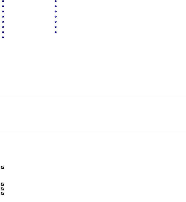
Product Overview
Front Panel Controls
1Power switch
2Media door (mailslot)
3Front panel LEDs
4Front panel LCD screen
5Function keys
6Left magazine
7Right magazine (or blank)
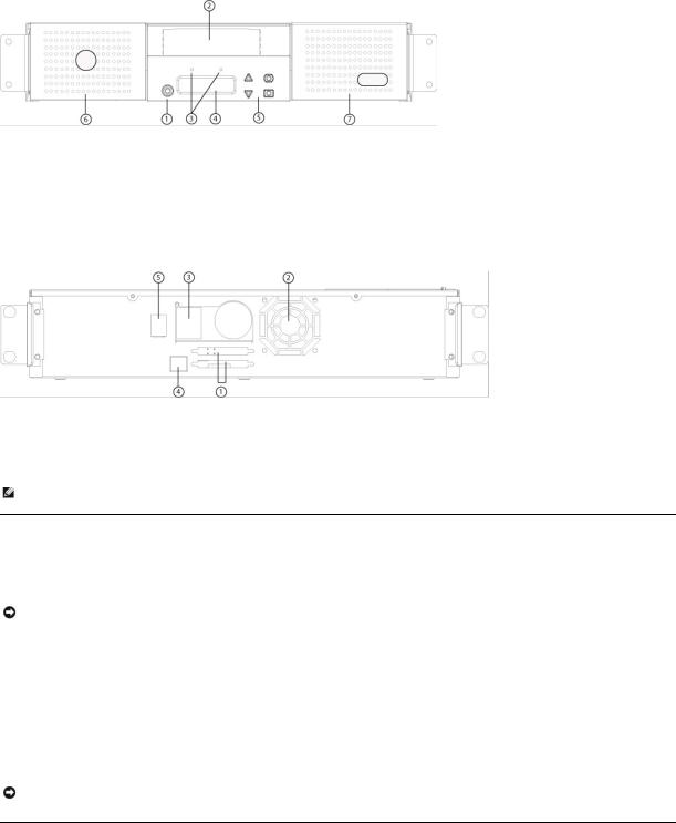
Back Panel Overview
168-pin HD SCSI connectors
2Fan vent
3Power connector
4Ethernet connector
5Power switch
NOTE: If the cover must be taken off, there are 26 screws and 6 rail bolts that need to be removed. The cover should be removed only by a qualified Dell Service Provider.
Unpacking the Autoloader
Before you begin, clear a desk or table so that you can unpack the autoloader. You also need to select an open 2U computer rack location near the server that will host the autoloader.
NOTICE: If the room in which you are working differs from the temperature in which the autoloader was shipped or stored by 15°C (30°
F) or more, let the autoloader acclimate to the surrounding environment for at least 12 hours before opening the shipping carton.
Unpack and inspect the autoloader for shipping damage by doing the following:
1.Clear a table or desk so that you have room to unpack the autoloader.
2.Inspect the shipping box for damage. If you notice any damage, report it to the shipping company immediately.
3.Open the shipping box and remove the accessories package. Set the accessories package aside for now.
4.Lift the autoloader and padding out of the box and place it on the work surface, top facing up. Do not set the autoloader on either end or sides.
5.Carefully remove the shipping padding from the front and back of the autoloader. Then remove the bag from the autoloader. Save the packing materials in case you need to move or ship the autoloader in the future. Illustrations on the box flaps indicate proper placement of the packaging materials.
NOTICE: If your unit was ordered as a one-magazine autoloader, be sure to remove the plastic shipping insert from the magazine bay before connecting or operating your autoloader. Insert either a magazine or a magazine blank into the bay. The autoloader will not function without both magazine bays equipped with either a magazine or a magazine blank.
Identifying Product Components
Accessories
 Loading...