


Dell™ PowerEdge™ 2850 Systems Installation and Troubleshooting Guide
Introduction
Indicators, Messages, and Codes
Finding Software Solutions
Running System Diagnostics
Troubleshooting Your System
Installing System Options
Installing Drives
Getting Help
Jumpers and Connectors
I/O Connectors
Notes, Notices, and Cautions
NOTE: A NOTE indicates important information that helps you make better use of your computer.
NOTICE: A NOTICE indicates either potential damage to hardware or loss of data and tells you how to avoid the problem.
CAUTION: A CAUTION indicates a potential for property damage, personal injury, or death.
Abbreviations and Acronyms
For a complete list of abbreviations and acronyms, see the "Glossary" in the User's Guide.
Information in this document is subject to change without notice.
© 2004 Dell Inc. All rights reserved.
Reproduction in any manner whatsoever without the written permission of Dell Inc. is strictly forbidden.
Trademarks used in this text: Dell, the DELL logo, Inspiron, Dell Precision, Dimension, OptiPlex, PowerApp, PowerEdge, PowerConnect, PowerVault, DellNet, Axim, and Latitude are trademarks of Dell Inc.; Microsoft, MS-DOS, and Windows are registered trademarks of Microsoft Corporation.
Other trademarks and trade names may be used in this document to refer to either the entities claiming the marks and names or their products. Dell Inc. disclaims any proprietary interest in trademarks and trade names other than its own.
June 2004

Back to Contents Page
Jumpers and Connectors
Dell™ PowerEdge™ 2850 Systems Installation and Troubleshooting Guide
Jumpers—A General Explanation
System Board Jumpers
System Board Connectors
Expansion-Card Riser-Board Components and PCI Buses
SCSI Backplane Board Connectors
Disabling a Forgotten Password
This section provides detailed information about the system jumpers. It also provides some basic information on jumpers and switches and describes the connectors on the various boards in the system.
Jumpers—A General Explanation
Jumpers provide a convenient and reversible way of reconfiguring the circuitry on a printed circuit board. When reconfiguring the system, you may need to change jumper settings on circuit boards or drives.
Jumpers
Jumpers are small blocks on a circuit board with two or more pins emerging from them. Plastic plugs containing a wire fit down over the pins. The wire connects the pins and creates a circuit. To change a jumper setting, pull the plug off its pin(s) and carefully fit it down onto the pin(s) indicated. Figure A-1 shows an example of a jumper.
Figure A-1. Example Jumpers
CAUTION: Ensure that the system is turned off before you change a jumper setting. Otherwise, damage to the system or unpredictable results may occur.
A jumper is referred to as open or unjumpered when the plug is pushed down over only one pin or if there is no plug at all. When the plug is pushed down over two pins, the jumper is referred to as jumpered. The jumper setting is often shown in text as two numbers, such as 1-2. The number 1 is printed on the circuit board so that you can identify each pin number based on the location of pin 1.
Figure A-2 shows the location and default settings of the system jumper blocks. See Table A-1 for information about the system jumper designations, default settings, and functions.
System Board Jumpers
Figure A-2 shows the location of the configuration jumpers on the system board. Table A-1 lists the settings for the jumpers.
NOTE: Lift up the memory module airflow shroud for easy access to the jumpers.
Figure A-2. System Board Jumpers
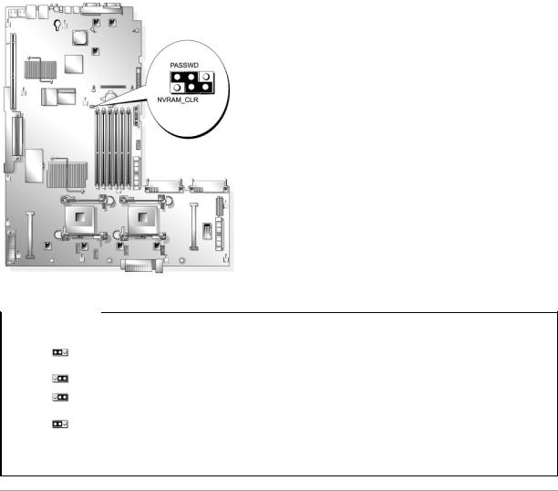
Table A-1. System Board Jumper Settings
Jumper |
Setting |
Description |
|
|
|
PASSWD |
|
The password feature is enabled. |
|
(default) |
|
|
|
|
|
|
The password feature is disabled. |
|
|
|
NVRAM_CLR |
|
The configuration settings are retained at system boot. |
|
(default) |
|
|
|
|
|
|
The configuration settings are cleared at the next system boot. (If the configuration settings become corrupted to the point |
|
|
where the system will not boot, install the jumper and boot the system. Remove the jumper before restoring the configuration |
|
|
information.) |
NOTE: For the full name of an abbreviation or acronym used in this table, see the "Glossary" in the User's Guide.
System Board Connectors
See Figure A-3 and Table A-2 for the location and description of system board connectors.
Figure A-3. System Board Connectors
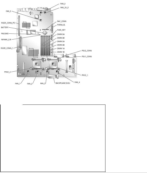
Table A-2. System Board Connectors
Connector |
Description |
|
|
BACKPLANE 2U5U |
Backplane connector |
|
|
BATTERY |
System battery |
|
|
DIMM nX |
Memory modules (6), where n is the slot in the bank and X is the bank |
FAN_n |
Cooling fans: |
|
• 1 — optional microprocessor 2 |
|
• 2, 3, 4 — microprocessor 1 |
|
• 5, 2U_6 — system fans |
|
|
PROC n |
Microprocessors (2) |
PSUn_CONN |
Power supply connectors (2) |
|
|
RAC_CONN |
Remote access control (RAC) card |
|
|
RAID_KEY |
Hardware key for optional integrated RAID controller |
|
|
RISER_CONN_1 |
Riser board connector |
|
|
RISER_CONN_PCI |
Riser board PCI bus connector |
|
|
PARALLEL |
Parallel connector |
|
|
NOTE: For the full name of an abbreviation or acronym used in this table, see the "Glossary" in the User's Guide.
Expansion-Card Riser-Board Components and PCI Buses
Figure A-4 shows the components on the PCI-X expansion-card riser board, including the expansion-card slots and buses. Table 6-1 lists the PCI bus and operating speed for each expansion-card slot. Figure A-5 shows the components on the optional PCI-X/PCIe expansion-card riser board, including the expansion-card slots and buses. Table 6-2 lists the PCI bus and operating speed for each expansion-card slot.
Figure A-4. PCI-X Expansion-Card Riser Board Components

Figure A-5 shows the components on the optional PCI-X/PCIe expansion-card riser board, including the expansion-card slots and buses. Table 6-2 lists the PCI bus and operating speed for each expansion-card slot.
Figure A-5. Optional PCI-X/PCIe Expansion-Card Riser Board Components
SCSI Backplane Board Connectors
Figure A-6 shows the location of the connectors on the SCSI backplane board.
Figure A-6. SCSI Backplane Board Components
Disabling a Forgotten Password
The system's software security features include a system password and a setup password, which are discussed in detail in "Using the System Setup Program" in the User's Guide. The password jumper enables these password features or disables them and clears any password(s) currently in use.
NOTICE: See "Protecting Against Electrostatic Discharge" in the safety instructions in your Product Information Guide.
1.Turn off the system, including any attached peripherals, and disconnect the system from the electrical outlet.
2.Open the system. See "Opening the System" in "Troubleshooting Your System."

3.Lift up the memory module shroud.
4.Remove the jumper plug from the password jumper.
See Figure A-2 to locate the password jumper (labeled "PASSWD") on the system board.
5.Close the system. See "Closing the System" in "Troubleshooting Your System."
6.Reconnect your system and peripherals to their electrical outlets, and turn on the system.
The existing passwords are not disabled (erased) until the system boots with the password jumper plug removed. However, before you assign a new system and/or setup password, you must install the jumper plug.
NOTE: If you assign a new system and/or setup password with the jumper plug still removed, the system disables the new password(s) the next time it boots.
7.Turn off the system, including any attached peripherals, and disconnect the system from the electrical outlet.
8.Open the system. See "Opening the System" in "Troubleshooting Your System."
9.Install the jumper plug on the password jumper.
10.Lower the memory module shroud.
11.Close the system. See "Closing the System" in "Troubleshooting Your System."
12.Reconnect your system and peripherals to their electrical outlets, and turn on the system.
13.Assign a new system and/or setup password.
To assign a new password using the System Setup program, see "Assigning a System Password" in the User's Guide.
Back to Contents Page
Back to Contents Page
I/O Connectors
Dell™ PowerEdge™ 2850 Systems Installation and Troubleshooting Guide
Serial Connector
PS/2-Compatible Keyboard and Mouse Connectors
Video Connector
USB Connectors
Integrated NIC Connectors
Network Cable Requirements
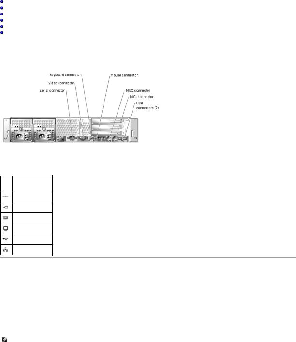
I/O connectors are the gateways that the system uses to communicate with external devices, such as a keyboard, mouse, printer, or monitor. This section describes the various connectors on your system. If you reconfigure the hardware connected to the system, you may also need the pin number and signal information for these connectors. Figure B-1 illustrates the connectors on the system.
Figure B-1. I/O Connectors
Table B-1 shows the icons used to label the connectors on the system.
Table B-1. I/O Connector Icons
Icon Connector
Serial connector
Mouse connector
Keyboard connector
Video connector
USB connector
NIC connector
Serial Connector
Serial connectors support devices such as external modems, printers, and mice that require serial data transmission. The serial connector uses a 9-pin D- subminiature connector.
Serial Connector Autoconfiguration
The default designation of the integrated serial connector is COM1. When you add an expansion card containing a serial connector that has the same designation as the integrated connector, the system's autoconfiguration feature remaps (reassigns) the integrated serial connector to the next available designation. Both the new and the remapped COM connectors share the same IRQ setting. COM1 and COM3 share IRQ4, while COM2 and COM4 share IRQ3.
NOTE: If two COM connectors share an IRQ setting, you may not be able to use them both at the same time. In addition, if you install one or more expansion cards with serial connectors designated as COM1 and COM3, the integrated serial connector is disabled.
Before adding a card that remaps the COM connectors, check the documentation that came with the software to make sure that the software can accommodate the new COM connector designation.
Figure B-2 illustrates the pin numbers for the serial connector and Table B-2 defines the pin assignments for the connector.
Figure B-2. Serial Connector Pin Numbers
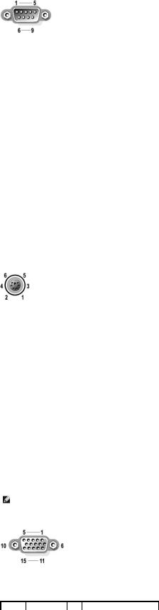
Table B-2. Serial Connector Pin Assignments
Pin |
Signal |
I/O |
Definition |
|
|
|
|
|
|
1 |
DCD |
I |
Data carrier detect |
|
|
|
|
|
|
2 |
SIN |
I |
Serial input |
|
|
|
|
|
|
3 |
SOUT |
O |
Serial output |
|
|
|
|
|
|
4 |
DTR |
O |
Data terminal ready |
|
|
|
|
|
|
5 |
GND |
N/A |
Signal ground |
|
|
|
|
|
|
6 |
DSR |
I |
Data set ready |
|
7 |
RTS |
O |
Request to send |
|
|
|
|
|
|
8 |
CTS |
I |
Clear to send |
|
|
|
|
|
|
9 |
RI |
I |
Ring indicator |
|
|
|
|
|
|
Shell |
N/A |
N/A |
Chassis ground |
|
|
|
|
|
|
|
|
|
|
|
PS/2-Compatible Keyboard and Mouse Connectors
The PS/2-compatible keyboard and mouse cables attach to 6-pin, miniature DIN connectors. Figure B-3 illustrates the pin numbers for these connectors and Table B-3 defines the pin assignments for these connectors.
Figure B-3. PS/2-Compatible Keyboard and Mouse Connector Pin Numbers
Table B-3. Keyboard and Mouse Connector Pin Assignments
Pin |
Signal |
I/O |
Definition |
|
|
|
|
|
|
1 |
KBDATA or MFDATA |
I/O |
Keyboard data or mouse data |
|
|
|
|
|
|
2 |
NC |
N/A |
No connection |
|
|
|
|
|
|
3 |
GND |
N/A |
Signal ground |
|
|
|
|
|
|
4 |
FVcc |
N/A |
Fused supply voltage |
|
|
|
|
|
|
5 |
KBCLK or MFCLK |
I/O |
Keyboard clock or mouse clock |
|
|
|
|
|
|
6 |
NC |
N/A |
No connection |
|
Shell |
N/A |
N/A |
Chassis ground |
|
|
|
|
|
|
|
|
|
|
|
Video Connector
You can attach a VGA-compatible monitor to the system's integrated video controller using a 15-pin high-density D-subminiature connector on the system front or back panel. Figure B-4 illustrates the pin numbers for the video connector and Table B-4 defines the pin assignments for the connector.
NOTE: Installing a video card automatically disables the system's integrated video controller.
Figure B-4. Video Connector Pin Numbers
Table B-4. Video Connector Pin Assignments
Pin |
Signal |
I/O |
Definition |
|
|
|
|
|
|
1 |
RED |
O |
Red video |
|
2 |
GREEN |
O |
Green video |
|
|
|
|
|
|
3 |
BLUE |
O |
Blue video |
|
|
|
|
|
|
4 |
NC |
N/A |
No connection |
|
|
|
|
|
|
5–8, 10 |
GND |
N/A |
Signal ground |
|
|
|
|
|
|
9 |
VCC |
N/A |
Vcc |
|
|
|
|
|
|
11 |
NC |
N/A |
No connection |
|
|
|
|
|
|
12 |
DDC data out |
O |
Monitor detect data |
|
|
|
|
|
|
13 |
HSYNC |
O |
Horizontal synchronization |
|
14 |
VSYNC |
O |
Vertical synchronization |
|
|
|
|
|
|
15 |
NC |
N/A |
No connection |
|
|
|
|
|
|
|
|
|
|
|
USB Connectors
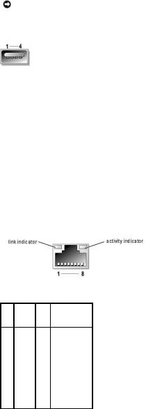
The system's USB connectors support USB-compliant peripherals such as keyboards, mice, and printers and may also support USB-compliant devices such as diskette drives and optical drives. Figure B-5 illustrates the pin numbers for the USB connector and Table B-5 defines the pin assignments for the connector.
NOTICE: Do not attach a USB device or a combination of USB devices that draw a maximum current of more than 500 mA per channel or +5 V. Attaching devices that exceed this threshold may cause the USB connectors to shut down. See the documentation that accompanied the USB devices for their maximum current ratings.
Figure B-5. USB Connector Pin Numbers
Table B-5. USB Connector Pin Assignments
Pin |
Signal |
I/O |
Definition |
|
|
|
|
|
|
1 |
Vcc |
N/A |
Supply voltage |
|
|
|
|
|
|
2 |
DATA |
I |
Data in |
|
|
|
|
|
|
3 |
+DATA |
O |
Data out |
|
4 |
GND |
N/A |
Signal ground |
|
|
|
|
|
|
|
|
|
|
|
Integrated NIC Connectors
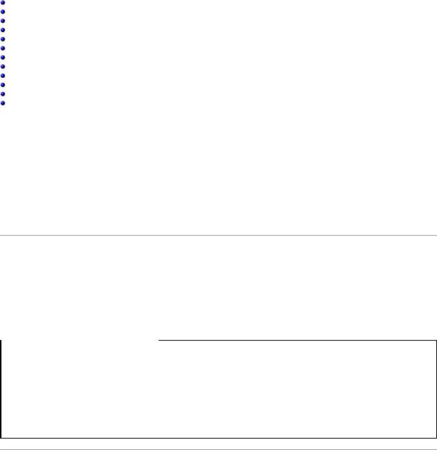
Each of the system's integrated NIC's function as a separate network expansion card while providing fast communication between servers and workstations. Figure B-6 illustrates the pin numbers for the NIC connector and Table B-6 defines the pin assignments for the connectors.
Figure B-6. NIC Connector
Table B-6. NIC Connector Pin Assignments
Pin Signal I/O Definition
1 |
TD+ |
O |
Data out (+) |
|
2 |
TD– |
O |
Data out (–) |
|
|
|
|
|
|
3 |
RD+ |
I |
Data in (+) |
|
|
|
|
|
|
4 |
NC |
N/A |
No connection |
|
|
|
|
|
|
5 |
NC |
N/A |
No connection |
|
|
|
|
|
|
6 |
RD– |
I |
Data in (–) |
|
|
|
|
|
|
7 |
NC |
N/A |
No connection |
|
8 |
NC |
N/A |
No connection |
|
|
|
|
|
|

Network Cable Requirements
The NIC supports a UTP Ethernet cable equipped with a standard RJ45-compatible plug. Observe the following cabling restrictions.
NOTICE: To avoid line interference, voice and data lines must be in separate sheaths.
•Use Category 5 or greater wiring and connectors.
•Do not exceed a cable run length (from a workstation to a hub) of 100 m (328 ft).
For detailed guidelines on operation of a network, see "Systems Considerations of Multi-Segment Networks" in the IEEE 802.3 standard.
Back to Contents Page
Back to Contents Page
Introduction
Dell™ PowerEdge™ 2850 Systems Installation and Troubleshooting Guide
Other Documents You May Need
Obtaining Technical Assistance
Your high-speed system offers significant service and upgrade features. The system includes the following service features to make troubleshooting and repair easy and effective:
•Embedded remote access hardware, which monitors temperatures and voltages throughout the system and notifies you if the system overheats, if a system cooling fan malfunctions, or if a power supply fails
•Redundant, hot-pluggable cooling fans
•Redundant, hot-pluggable power supplies
•System diagnostics, which checks for hardware problems (if the system can boot)
System upgrade options are offered, including:
•An additional microprocessor
•Additional system memory
•A variety of PCI, PCI Express (PCIe), and PCI-X expansion-card options (including RAID controller cards)
•An integrated RAID controller that can be activated with an additional memory module, key, and battery
Other Documents You May Need
The Product Information Guide provides important safety and regulatory information. Warranty information may be included within this document or as a separate document.
•The Rack Installation Guide or Rack Installation Instructions included with your rack solution describes how to install your system into a rack.
•The Getting Started Guide provides an overview of initially setting up your system.
•The User's Guide provides information about system features and technical specifications.
•The Installation and Troubleshooting Guide describes how to troubleshoot the system and install or replace system components.
•Systems management software documentation describes the features, requirements, installation, and basic operation of the software.
•Operating system documentation describes how to install (if necessary), configure, and use the operating system software.
•Documentation for any components you purchased separately provides information to configure and install these options.
•Updates are sometimes included with the system to describe changes to the system, software, and/or documentation.
 NOTE: Always read the updates first because they often supersede information in other documents.
•Release notes or readme files may be included to provide last-minute updates to the system or documentation or advanced technical reference material intended for experienced users or technicians.
Obtaining Technical Assistance
If at any time you do not understand a procedure described in this guide or if your system does not perform as expected, a number of tools are provided to help you. For more information on these help tools, see "Getting Help."
Back to Contents Page
Back to Contents Page
Indicators, Messages, and Codes
Dell™ PowerEdge™ 2850 Systems Installation and Troubleshooting Guide
Indicators on the Optional Bezel
Front-Panel Indicators and Features
SCSI Hard-Drive Indicator Codes
Back-Panel Indicators and Features
Power Indicator Codes
NIC Indicator Codes
LCD Status Messages
System Messages
System Beep Codes
Warning Messages
Diagnostics Messages
Alert Messages
The system, applications, and operating systems can identify problems and alert you to them. Any of the following can indicate when the system is not operating properly:
•System indicators
•System messages
•Beep codes
•Warning messages
•Diagnostics messages
•Alert messages
This section describes each type of message, lists the possible causes, and provides steps to resolve any problems indicated by a message. The system indicators and features are illustrated in this section.
Indicators on the Optional Bezel
The optional locking system bezel incorporates blue and amber system status indicators.
The blue indicator lights up when the system is operating correctly. The amber indicator lights up when the system needs attention due to a problem with power supplies, fans, system temperature, or hard drives. The back-panel indicator connector allows an indicator to be attached that will also function the same as the bezel indicator. See Figure 2-3.
Table 2-1 lists the system's indicator patterns. Different patterns are displayed as events occur in the system.
Table 2-1. System Status Indicator Patterns
Blue indicator |
Amber indicator |
Description |
|
|
|
Off |
Off |
Power is not available to the system |
Off |
Blinking |
The system has detected an error. |
|
|
|
On |
Off |
Power is on, and the system is operational. |
|
|
|
Blinking |
Off |
The indicator has been activated to identify the system in a rack. |
|
|
|
NOTE: While the system is being identified, the blue indicator blinks even though an error has been detected. After the system is identified, the blue indicator stops blinking and the amber indicator resumes blinking.
Front-Panel Indicators and Features
Additional indicators are located behind the bezel. The front-panel status LCD provides information using an alphanumeric character display. See "LCD Status Messages."
Figure 2-1 shows the front-panel indicators and features of the system. Table 2-2 describes the front-panel features.
Figure 2-1. Front-Panel Features
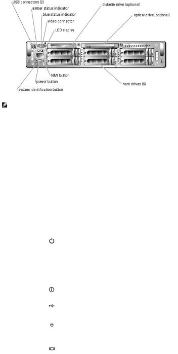
NOTE: Hard drives bays are numbered 0 through 5 starting at the lower leftmost drive bay.
Table 2-2. Front-Panel LED Indicators, Buttons, and Connectors
Indicator, Button, |
Icon |
Description |
or Connector |
|
|
|
|
|
blue system status |
|
Does not operate when the optional bezel is removed. The LCD display indicates the status. |
indicator |
|
|
|
|
|
amber system |
|
Does not operate when the optional bezel is removed. The LCD display indicates the status. |
status indicator |
|
|
|
|
|
LCD display |
|
Provides system ID, status information, and system error messages. |
|
|
The LCD display lights up during normal system operation. Both the systems management software and the identification |
|
|
buttons located on the front and back of the system can cause the LCD to flash blue to identify a particular system. |
|
|
The LCD display flashes amber when the system needs attention due to a problem with power supplies, fans, system |
|
|
temperature, or hard drives. |
|
|
NOTE: If the system is connected to AC power and an error has been detected, the LCD display flashes amber regardless of |
|
|
whether the system has been powered on. |
|
|
|
power-on indicator, |
|
The power-on indicator lights when the system power is on. The power-on indicator blinks when power is available to the |
power button |
|
system, but the system is not powered on. |
|
|
The power button controls the DC power supply output to the system. |
|
|
NOTE: If you turn off the system using the power button and the system is running an ACPI-compliant operating system, the |
|
|
system performs a graceful shutdown before the power is turned off. If the system is not running an ACPI-compliant |
|
|
operating system, the power is turned off immediately after the power button is pressed. |
|
|
|
system |
|
The identification buttons on the front and back panels can be used to locate a particular system within a rack. When one of |
identification button |
|
these buttons is pushed, the blue system status indicator on the front and back blinks until one of the buttons is pushed |
|
|
again. |
|
|
|
USB connectors |
|
Connects USB 2.0-compliant devices to the system. |
|
|
|
NMI button |
|
Used to troubleshoot software and device driver errors when using certain operating systems. This button can be pressed |
|
|
using the end of a paper clip. |
|
|
Use this button only if directed to do so by qualified support personnel or by the operating system's documentation. |
|
|
|
video connector |
|
Connects a monitor to the system. |
|
|
|
|
|
|
SCSI Hard-Drive Indicator Codes
If RAID is activated, two indicators on each of the hard-drive carriers provide information on the status of the SCSI hard drives. RAID can be enabled either by using ROMB on the optional riser card or by using a RAID card connected to the backplane. See Figure 2-2 and Table 2-3. The SCSI backplane firmware controls the drive power-on/fault indicator.
Figure 2-2. SCSI Hard-Drive Indicators

Table 2-3 lists the drive indicator patterns. Different patterns are displayed as drive events occur in the system. For example, if a hard-drive fails, the "drive failed" pattern appears. After the drive is selected for removal, the "drive being prepared for removal" pattern appears, followed by the "drive ready for insertion or removal" pattern. After the replacement drive is installed, the "drive being prepared for operation" pattern appears, followed by the "drive online" pattern.
NOTE: If RAID is not activated, only the "drive online" indicator pattern appears. The drive-activity indicator also blinks when the drive is being accessed.
Table 2-3. Hard-Drive Indicator Patterns
Condition |
Indicator Pattern |
|
Identify drive |
The green power-on/fault indicator blinks four times per second. |
|
|
|
|
Drive being prepared for removal |
The green power-on/fault indicator blinks two times per second. |
|
|
|
|
Drive ready for insertion or removal |
Both drive indicators are off. |
|
|
|
|
Drive being prepared for operation |
The green power-on/fault indicator is on. |
|
|
|
|
Drive predicted failure |
The power-on/fault indicator slowly blinks green, amber, and off. |
|
|
|
|
Drive failed |
The amber power-on/fault indicator blinks four times per second. |
|
|
|
|
Drive rebuilding |
The green power-on/fault indicator blinks slowly. |
|
|
|
|
Drive online |
The green power-on/fault indicator is on. |
|
|
|
|
Back-Panel Indicators and Features
Figure 2-3 shows the back-panel features of the system. Table 2-4 describes the back-panel features.
Figure 2-3. Back-Panel Features
Table 2-4. Back-Panel Features
Component |
Description |
|
|
Power supply indicators |
Provides information on power status. See "Power Indicator Codes." |
|
|
NIC indicators |
Provides information on NIC status. See "NIC Indicator Codes." |
|
|
|
|
System status indicator |
Connects to an indicator that can signify when the system is operating correctly or when the system needs attention. See |
connector |
"Indicators on the Optional Bezel." |
|
|
System identification |
Signifies when the system is operating correctly or when the system needs attention, and can identify a particular system. |
indicator |
|
System identification button |
Can be used to identify a particular system. |
|
|
|
|
Power Indicator Codes
The system has indicators on the front panel and the power supplies that signify system power status.
Power-Button Indicator Codes
The power button on the front panel controls the power input to the system's power supplies. The power indicator can provide information on power status. See Figure 2-1. Table 2-5 lists the power button indicator codes.
Table 2-5. Power-Button Indicator Codes
Indicator |
Indicator Code |
|
|
On |
Indicates that power is supplied to the system, and the system is operational. |
|
|
Off |
Indicates that no power is supplied to the system. |
|
|
Blinking |
Indicates that power is supplied to the system, but the system is in a standby state. For more information on standby states, see your operating |
|
system documentation. |
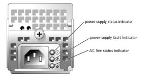
Redundant Power-Supply Indicator Codes
The indicators on the optional redundant power supplies show whether power is present or whether a power fault has occurred. See Figure 2-4. Table 2-6 lists the power-supply indicator codes.
Figure 2-4. Redundant Power-Supply Indicators
Table 2-6. Power-Supply Indicator Codes
Indicator |
Indicator Code |
|
|
|
|
Power-on |
Green indicates that the power supply is operational. |
|
|
|
|
Fault |
Red indicates a problem with the power supply (fan failure, voltage error, etc.). |
|
|
|
|
Power present |
Green indicates that power is present at the power supply and that the system is connected to a power source. |
|
|
|
|
|
|
|
NIC Indicator Codes
Each NIC on the back panel has an indicator that provides information on network activity and link status. See Figure 2-5. Table 2-7 lists the NIC indicator codes on the back panel.
Figure 2-5. NIC Indicators
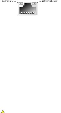
Table 2-7. NIC Indicator Codes
Indicator |
Indicator Code |
|
|
|
|
Link and activity indicators are off |
The NIC is not connected to the network. |
|
|
|
|
Link indicator is green |
The NIC is connected to a valid link partner on the network. |
|
|
|
|
Activity indicator is amber blinking |
Network data is being sent or received. |
|
|
|
|
LCD Status Messages
The system's bezel indictor can signify when the system is operating correctly or when the system needs attention. When the bezel indicator signifies an error condition, remove the bezel to see further information provided by the status LCD.
The LCD can display two lines of alphanumeric characters. The display codes are presented in two color combinations:
•White characters on a blue background — Information only; no action is required.
•Amber characters on a black background — The system needs attention.
Table 2-8 lists the LCD status messages that can occur and the probable cause for each message. The LCD messages refer to events recorded in the SEL. For information on the SEL and configuring system management settings, see the systems management software documentation.
CAUTION: Only trained service technicians are authorized to remove the system cover and access any of the components inside the system. See your Product Information Guide for complete information about safety precautions, working inside the computer, and protecting against electrostatic discharge.
Table 2-8. LCD Status Messages
Line 1 |
Line 2 |
Causes |
Corrective Actions |
Message |
Message |
|
|
|
|
|
|
SYSTEM |
SYSTEM NAME |
SYSTEM ID is a unique name, five characters or |
This message is for information only. |
ID |
|
less, defined by the user. |
|
|
|
|
You can change the system ID and name in the System Setup program. See |
|
|
SYSTEM NAME is a unique name, 16 characters or |
your system's User's Guide for instructions. |
|
|
less, defined by the user. |
|
|
|
The system ID and name display under the |
|
|
|
following conditions: |
|
|
|
• The system is powered on. |
|
|
|
• The power is off and active POST errors are |
|
|
|
displayed. |
|
|
|
|
|
E0000 |
OVRFLW CHECK |
LCD overflow message. |
Check the SEL for details on the events. |
|
LOG |
|
|
|
|
A maximum of three error messages can display |
|
|
|
sequentially on the LCD. The fourth message |
|
|
|
displays as the standard overflow message. |
|
|
|
|
|
E0119 |
TEMP AMBIENT |
Ambient system temperature is out of acceptable |
See "Troubleshooting System Cooling Problems" in "Troubleshooting Your |
|
|
range. |
System." |
|
|
|
|
E0119 |
TEMP BP |
Backplane board is out of acceptable temperature |
|
|
|
range. |
|
E0119 |
TEMP CPU n |
Specified microprocessor is out of acceptable |
See "Troubleshooting System Cooling Problems" in "Troubleshooting Your |
|
|
temperature range. |
System." If the problem persists, ensure that the microprocessor heat sinks |
|
|
|
are properly installed (see "Processors" in "Installing System Options"). |
|
|
|
|
E0119 |
TEMP SYSTEM |
System board is out of acceptable temperature |
See "Troubleshooting System Cooling Problems" in "Troubleshooting Your |
|
|
range. |
System." |
|
|
|
|
E0212 |
VOLT 3.3 |
System power supply is out of acceptable voltage |
See "Troubleshooting Power Supplies" in "Troubleshooting Your System." |
|
|
range; faulty or improperly installed power supply. |
|
E0212 |
VOLT 5 |
|
|
|
|
||
E0212 |
VOLT 12 |
|
|
|
|
|
|
E0212 |
VOLT BATT |
Faulty battery; faulty system board. |
See "Troubleshooting the System Battery" in "Troubleshooting Your |
|
|
|
System." |
|
|
|
|
E0212 |
VOLT BP 12 |
Backplane board is out of acceptable voltage |
Ensure that the power cables are securely connected to the backplane |
|
|
range. |
board (see "Installing Drives"). If the problem persists, see |
|
E0212 |
VOLT BP 3.3 |
|||
|
"Troubleshooting Power Supplies" in "Troubleshooting Your System." |
|||
E0212 |
VOLT BP 5 |
|
|
|
|
|
|
|
|
E0212 |
VOLT CPU VRM |
Microprocessor VRM voltage is out of acceptable |
This message is not applicable to this system. |
|
|
|
range; faulty or improperly installed microprocessor |
|
|
|
|
VRM; faulty system board. |
|
|
|
|
|
|
|
E0212 |
VOLT NIC 1.8V |
Integrated NIC voltage is out of acceptable range; |
See "Troubleshooting Power Supplies" in "Troubleshooting Your System." |
|
|
|
faulty or improperly installed power supply; faulty |
|
|
|
|
|
||
E0212 |
VOLT NIC 2.5V |
system board. |
|
|
|
|
|
|
|
E0212 |
VOLT PLANAR |
System board is out of acceptable voltage range; |
|
|
|
REG |
faulty or improperly installed system board. |
|
|
|
|
|
|
|
E0276 |
CPU VRM n |
Specified microprocessor VRM is faulty, |
These messages are not applicable to this system. |
|
|
|
unsupported, improperly installed, or missing. |
|
|
E0276 |
MISMATCH VRM |
|
||
|
|
|||
|
n |
|
|
|
|
|
|
|
|
E0280 |
MISSING VRM n |
|
|
|
|
|
|
|
|
E0319 |
PCI OVER |
Faulty or improperly installed expansion card. |
See "Troubleshooting Expansion Cards" in "Troubleshooting Your System." |
|
|
CURRENT |
|
|
|
|
|
|
|
|
E0412 |
RPM FAN n |
Specified cooling fan is faulty, improperly installed, |
See "Troubleshooting a Fan" in "Troubleshooting Your System." |
|
|
|
or missing. |
|
|
E0780 |
MISSING CPU 1 |
Microprocessor is not installed in socket PROC_1. |
Install a microprocessor in socket PROC_1 (see "Processors" in "Installing |
|
|
|
|
System Options"). To identify microprocessor socket PROC_1, see Figure A- |
|
|
|
|
3. |
|
|
|
|
|
|
E07F0 |
CPU IERR |
Faulty or improperly installed microprocessor. |
See "Troubleshooting the Microprocessors" in "Troubleshooting Your |
|
|
|
|
System." |
|
E07F1 |
TEMP CPU n |
Specified microprocessor is out of acceptable |
See "Troubleshooting System Cooling Problems" in "Troubleshooting Your |
|
|
HOT |
temperature range and has halted operation. |
System." If the problem persists, ensure that the microprocessor heat sinks |
|
|
|
|
are properly installed (see "Processors" in "Installing System Options"). |
|
E07F4 |
POST CACHE |
Faulty or improperly installed microprocessor. |
See "Troubleshooting the Microprocessors" in "Troubleshooting Your |
|
|
|
|
System." |
|
E07F4 |
POST CPU REG |
|
||
|
|
|||
|
|
|
|
|
E07F4 |
POST CPU SMI |
SMI handler failed to initialize; faulty system board. |
See "Getting Help." |
|
E07FA |
TEMP CPU n |
Specified microprocessor is out of acceptable |
See "Troubleshooting System Cooling Problems" in "Troubleshooting Your |
|
|
THERM |
temperature range and is operating at a reduced |
System." If the problem persists, ensure that the microprocessor heat sinks |
|
|
|
speed, or frequency. |
are properly installed (see "Processors" in "Installing System Options"). |
|
E0876 |
POWER PS n |
No power available from the specified power |
See "Troubleshooting Power Supplies" in "Troubleshooting Your System." |
|
|
|
supply; specified power supply is improperly |
|
|
|
|
installed or faulty. |
|
|
|
|
|
|
|
E0880 |
INSUFFICIENT |
Insufficient power is being supplied to the system; |
See "Troubleshooting Power Supplies" in "Troubleshooting Your System." |
|
|
PS |
power supplies are improperly installed, faulty, or |
|
|
|
|
missing. |
|
|
E0CB2 |
MEM SPARE ROW |
Correctable errors threshold was met in a memory |
See "Troubleshooting System Memory" in "Troubleshooting Your System." |
|
|
|
bank: errors were remapped to the spare row. |
|
|
|
|
|
|
|
E0CF1 |
MBE DIMM Bank |
Memory modules installed in the specified bank are |
Ensure that all banks contain memory modules of the same type and size |
|
|
n |
not the same type and size; faulty memory module |
and that they are properly installed. If the problem persists, see |
|
|
|
(s). |
"Troubleshooting System Memory" in "Troubleshooting Your System." |
|
E0CF1 |
POST MEM 64K |
Parity failure in the first 64 KB of main memory. |
See "Troubleshooting System Memory" in "Troubleshooting Your System." |
|
|
|
|
|
|
E0CF1 |
POST NO |
Main-memory refresh verification failure. |
Ensure that all banks contain memory modules of the same type and size |
|
|
MEMORY |
|
and that they are properly installed. If the problem persists, see |
|
|
|
|
"Troubleshooting System Memory" in "Troubleshooting Your System." |
|
E0CF5 |
LOG DISABLE |
Multiple single-bit errors on a single memory |
See "Troubleshooting System Memory" in "Troubleshooting Your System." |
|
|
SBE |
module. |
|
|
|
|
|
|
|
E0D76 |
DRIVE FAIL |
Faulty or improperly installed hard drive or RAID |
See "Troubleshooting SCSI Hard Drives" and "Troubleshooting a RAID |
|
|
|
controller. |
Controller Card" in "Troubleshooting Your System." |
|
|
|
|
|
|
E0F04 |
POST CMOS |
CMOS write/read failure; faulty system board. |
See "Getting Help." |
|
|
|
|
|
|
E0F04 |
POST CPU |
Microprocessor speed control sequence failure. |
See "Getting Help." |
|
|
SPEED |
|
|
|
E0F04 |
POST DMA INIT |
DMA initialization failure; DMA page register |
See "Troubleshooting System Memory" in "Troubleshooting Your System." |
|
|
|
write/read failure. |
|
|
|
|
|
|
|
E0F04 |
POST DMA REG |
Faulty system board. |
See "Getting Help." |
|
|
|
|
|
|
E0F04 |
POST KYB |
Faulty keyboard controller; faulty system board. |
See "Getting Help." |
|
|
CNTRL |
|
|
|
|
|
|
|
|
E0F04 |
POST MEM RFSH |
Main-memory refresh verification failure. |
See "Troubleshooting System Memory" in "Troubleshooting Your System." |
|
E0F04 |
POST PIC REG |
Master or slave PIC register test failure. |
See "Getting Help." |
|
|
|
|
|
|
E0F04 |
POST SHADOW |
BIOS-shadowing failure. |
See "Troubleshooting System Memory" in "Troubleshooting Your System." |
|
|
|
|
|
|
E0F04 |
POST SHD TEST |
Shutdown test failure. |
|
|
|
|
|
|
|
E0F04 |
POST SIO |
Super I/O chip failure; faulty system board. |
See "Getting Help." |
|
|
|
|
|
|
E0F04 |
POST TIMER |
Programmable interval timer test failure; faulty |
See "Getting Help." |
|
|
|
system board. |
|
|
E0F0B |
POST ROM |
Faulty or improperly installed expansion card. |
See "Troubleshooting Expansion Cards" in "Troubleshooting Your System." |
|
|
CHKSUM |
|
|
|
|
|
|
|
|
E0F0C |
VID MATCH CPU |
Specified microprocessor is faulty, unsupported, |
See "Troubleshooting the Microprocessors" in "Troubleshooting Your |
|
|
n |
improperly installed, or missing. |
System." |
|
|
|
|
|
|
|
|
|
|

E10F3 |
LOG DISABLE |
BIOS disabled logging errors. |
Check the SEL for details on the errors. |
|
BIOS |
|
|
E13F2 |
IO CHANNEL |
Faulty or improperly installed expansion card; faulty |
See "Troubleshooting Expansion Cards" in "Troubleshooting Your System." |
|
CHECK |
system board. |
|
|
|
|
|
E13F4 |
PCI PARITY |
|
|
|
|
|
|
E13F5 |
PCI SYSTEM |
|
|
|
|
|
|
E13F8 |
CPU BUS INIT |
Faulty or improperly installed microprocessor or |
See "Troubleshooting the Microprocessors" in "Troubleshooting Your |
|
|
system board. |
System." If the problem persists, see "Getting Help." |
E13F8 |
CPU BUS |
Faulty system board. |
See "Getting Help." |
|
PARITY |
|
|
|
|
|
|
E13F8 |
CPU MCKERR |
Machine check error; faulty or improperly installed |
See "Troubleshooting the Microprocessors" in "Troubleshooting Your |
|
|
microprocessor; faulty system board. |
System." |
E13F8 |
HOST BUS |
Faulty system board. |
See "Getting Help." |
|
|
|
|
E13F8 |
HOST TO PCI |
|
|
|
BUS |
|
|
|
|
|
|
E13F8 |
MEM |
Faulty or improperly installed memory module; |
See "Troubleshooting System Memory" in "Troubleshooting Your System." |
|
CONTROLLER |
faulty system board. |
|
|
|
|
|
E1580 |
POWER CONTROL |
Faulty system board. |
See "Getting Help." |
|
|
|
|
E20F1 |
OS HANG |
Operating system watchdog timer timed out. |
Restart your system. If the problem persists, see your operating system |
|
|
|
documentation. |
EFFF0 |
RAC ERROR |
Remote access controller firmware failure; faulty |
See "Getting Help." |
|
|
system board. |
|
EFFF1 |
POST ERROR |
BIOS error. |
Update the BIOS firmware (see "Getting Help"). |
|
|
|
|
EFFF2 |
BP ERROR |
Faulty or improperly installed backplane board. |
Ensure that the interface cables are securely connected to the backplane |
|
|
|
board (see "Installing Drives"). If the problem persists, see "Getting Help." |
|
|
|
|
NOTE: For the full name of an abbreviation or acronym used in this table, see the "Glossary" in the User's Guide.
Solving Problems Described by LCD Status Messages
When a single message appears on the status LCD, locate the code in Table 2-8 and perform the suggested corrective action. The code on the LCD can often specify a very precise fault condition that is easily corrected. For example, if the code E0780 MISSING CPU 1 appears, you know that a microprocessor is not installed in socket 1.
In contrast, you might be able to determine the problem if multiple related errors occur. For example, if you receive a series of messages indicating multiple voltage faults, you might determine that the problem is a failing power supply.
Removing LCD Status Messages
For faults associated with sensors, such as temperature, voltage, fans, and so on, the LCD message is automatically removed when that sensor returns to a normal state. For example, if temperature for a component goes out of range, the LCD displays the fault; when the temperature returns to the acceptable range, the message is removed from the LCD. For other faults, you must take action to remove the message from the display:
•Clear the SEL — You can perform this task remotely, but you will lose the event history for the system.
•Chassis intrusion — When you remove the cover, the system assumes that you are servicing the bad component; the LCD clears when you replace the cover.
•Power cycle — Turn off the system and disconnect it from the electrical outlet; wait approximately ten seconds, reconnect the power cable, and restart the system.
Any of these actions will remove fault messages, and return the status indicators and LCD colors to the normal state. Messages will reappear under the following conditions:
•The sensor returns to a normal state but fails again, resulting in a new SEL entry.
•The system is reset and new error events are detected.
•A failure is recorded from another source that maps to the same display entry.
System Messages
System messages appear on the screen to notify you of a possible problem with the system. Table 2-9 lists the system messages that can occur and the probable cause and corrective action for each message.
NOTE: If you receive a system message that is not listed in Table 2-9, check the documentation for the application that is running when the message appears or the operating system's documentation for an explanation of the message and recommended action.
CAUTION: Only trained service technicians are authorized to remove the system cover and access any of the components inside the system. See your Product Information Guide for complete information about safety precautions, working inside the computer, and protecting against electrostatic discharge.
Table 2-9. System Messages
Message |
Causes |
Corrective Actions |
|
|
|
|
|
Address mark not found |
Faulty optical/diskette drive subsystem |
See "Troubleshooting a Diskette Drive," "Troubleshooting |
|
|
or hard-drive subsystem; faulty system |
an Optical Drive," and "Troubleshooting SCSI Hard Drives" |
|
|
board. |
in "Troubleshooting Your System." |
|
|
|
|
|
Alert! Current configuration does not support |
Memory modules installed are not the |
Ensure that all banks contain memory modules of the same |
|
redundant memory. Redundant memory is disabled. |
same type and size in all banks; faulty |
type and size and that they are properly installed. If the |
|
|
memory module(s). |
problem persists, see "Troubleshooting System Memory" in |
|
|
|
"Troubleshooting Your System." |
|
Amount of available memory limited to 256 MB! |
OS Install Mode is enabled in the |
Disable OS Install Mode in the System Setup program. See |
|
|
System Setup program. |
"Using the System Setup program" in the User's Guide. |
|
|
|
|
|
Auxiliary device failure |
Loose or improperly connected mouse |
See "Troubleshooting the Mouse" and "Troubleshooting the |
|
|
or keyboard cable; faulty mouse or |
Keyboard" in "Troubleshooting Your System." |
|
|
keyboard. |
|
|
BIOS Update Attempt Failed! |
Remote BIOS update attempt failed. |
Retry the BIOS update. If problem persists, see "Getting |
|
|
|
Help." |
|
CD-ROM drive not found |
IDE CD-ROM Controller option is |
If the system does not have an optical drive, disable the |
|
|
enabled in the System Setup program, |
IDE CD-ROM Controller option in the System Setup |
|
|
but the optical drive is not detected. |
program. See "Using the System Setup program" in the |
|
|
|
User's Guide. |
|
|
|
If the system has an optical drive, ensure that it is properly |
|
|
|
connected. See "Troubleshooting an Optical Drive" in |
|
|
|
"Troubleshooting Your System. |
|
|
|
|
|
CPUs with different cache sizes detected |
Microprocessors with different cache |
Ensure that all microprocessors have the same cache size |
|
|
sizes are installed. |
and that they are properly installed. See "Processors" in |
|
|
|
"Installing System Options." |
|
Decreasing available memory |
Faulty or improperly installed memory |
See "Troubleshooting System Memory" in "Troubleshooting |
|
|
modules. |
Your System." |
|
|
|
|
|
Diskette drive n seek failure |
Incorrect configuration settings in the |
Run the System Setup program to correct the settings. See |
|
|
System Setup program. |
"Using the System Setup Program" in the User's Guide. |
|
|
|
|
|
|
Faulty or improperly installed diskette |
See "Troubleshooting a Diskette Drive" in "Troubleshooting |
|
|
drive. |
Your System." |
|
|
|
|
|
Diskette read failure |
Faulty or improperly inserted diskette. |
Replace the diskette. |
|
|
|
|
|
Diskette subsystem reset failed |
Faulty or improperly installed diskette |
See "Troubleshooting a Diskette Drive" in "Troubleshooting |
|
|
drive. |
Your System." |
|
ECC memory error |
Faulty or improperly installed memory |
See "Troubleshooting System Memory" in "Troubleshooting |
|
|
modules. |
Your System." |
|
|
|
|
|
Embedded RAID error |
Embedded RAID firmware responds |
See "Getting Help." |
|
|
with an error. |
|
|
|
|
|
|
Embedded RAID Firmware is not present |
Embedded RAID Firmware does not |
See "Getting Help." |
|
|
respond. |
|
|
|
|
|
|
Error: Incorrect memory configuration. |
Unmatched DIMM pairs are detected. |
Ensure that the memory modules are installed in matched |
|
|
|
pairs. See "General Memory Module Installation Guidelines" |
|
Ensure memory in slots DIMM1_A and DIMM1_B, |
|
in "Installing System Components." |
|
|
|
||
DIMM2_A and DIMM2_B, DIMM3_A and DIMM3_B match |
|
|
|
identically in size, speed, and rank. |
|
|
|
|
|
|
|
Error: Incorrect memory configuration. |
Dual-rank memory modules are |
Remove the memory modules from slots DIMM3_A and |
|
|
installed in memory slots DIMM3_A and |
DIMM3_B. See "General Memory Module Installation |
|
Memory slots DIMM3_A and DIMM3_B only support |
DIMM3_B. These memory slots do not |
Guidelines" in "Installing System Components." |
|
support dual-rank memory modules. |
|
||
single rank DIMMs. Remove the dual rank DIMMs |
|
||
|
|
||
from slots DIMM3_A and DIMM3_B. |
|
|
|
|
|
|
|
Error: Incorrect memory configuration. |
Memory modules are installed in |
Remove the memory modules from slots DIMM3_A and |
|
|
memory slots DIMM3_A and DIMM3_B. |
DIMM3_B. See "General Memory Module Installation |
|
Memory slots DIMM3_A and DIMM3_B must be empty if |
These memory slots must be empty if |
Guidelines" in "Installing System Components." |
|
dual rank DIMMs are installed in |
|
||
Dual Rank memory DIMMs are in slots DIMM2_A and |
|
||
memory slots DIMM2_A and DIMM2_B. |
|
||
DIMM2_B. |
|
||
|
|
||
|
|
|
|
Error: Incorrect memory configuration. |
Memory modules are not populated |
Move memory modules from memory slots DIMM3_A and |
|
|
from lowest-number bank to highest- |
DIMM3_B into memory slots DIMM2_A and DIMM2_B. See |
|
Move DIMM3_A and DIMM3_B into DIMM2_A and |
number bank. |
"General Memory Module Installation Guidelines" in |
|
|
"Installing System Components." |
||
DIMM2_B. |
|
||
|
|
||
|
|
|
|
Error: Incorrect memory configuration. |
Memory slots DIMM1_A and DIMM1_B |
Swap the memory modules in DIMM1_A and DIMM1_B with |
|
|
must be populated with dual-rank |
the memory modules in slots DIMM2_A and DIMM2_B. See |
|
Swap the DIMMs in slots DIMM1_A and DIMM1_B with |
DIMMs if dual-rank DIMMs are |
"General Memory Module Installation Guidelines" in |
|
populated in the system. |
"Installing System Components." |
||
DIMMs in slots DIMM2_A and DIMM2_B. |
|||
|
|
||
|
|
|
|
Error: Maximum PCI option ROM count exceeded! |
Too many expansion cards have ROM |
Disable ROM for some of the expansion cards. See "Using |
|
|
enabled in the System Setup program. |
the System Setup Program" in the User's Guide. |
|
|
|
|
|
Gate A20 failure |
Faulty keyboard controller; faulty |
See "Getting Help." |
|
|
system board. |
|
|
Hard disk controller failure |
Incorrect configuration settings in |
Run the System Setup program to correct the drive type. |
|
|
System Setup program; improperly |
See "Using the System Setup Program" in the User's Guide. |
|
|
installed hard drive, or loose interface |
If the problem persists, see "Troubleshooting SCSI Hard |
|
|
|||
Hard disk read failure |
or power cable; faulty hard-drive |
Drives" in "Troubleshooting Your System." |
|
|
controller subsystem. |
|
|
|
|
|
|
|
|
|
I/O parity interrupt at address |
Faulty or improperly installed |
See "Troubleshooting Expansion Cards" in |
|
|
expansion card. |
"Troubleshooting Your System." |
|
|
|
|
|
Invalid configuration information - please run |
Incorrect configuration settings in |
Check the System Setup configuration settings. See "Using |
|
SETUP program |
System Setup program; NVRAM_CLR |
the System Setup Program" in the User's Guide. Remove |
|
|
jumper is installed; faulty system |
the NVRAM_CLR jumper. See Figure A-2 for jumper location. |
|
|
battery. |
If the problem persists, see "Troubleshooting the System |
|
|
|
Battery" in "Troubleshooting Your System." |
|
|
|
|
|
Invalid NVRAM configuration, resource re- |
System configuration data has been |
Check the System Setup configuration settings. See "Using |
|
allocated |
ignored. |
the System Setup Program" in the User's Guide. |
|
|
|
|
|
Invalid SCSI configuration |
A SCSI cable is connected to the |
If a cable is connected to the SCSIB backplane board |
|
|
channel B connector on the SCSI |
connector, the SCSI backplane daughter card must be |
|
SCSI cable detected on connector SCSIB of the |
backplane board; SCSI backplane |
installed. Install the backplane daughter card. See |
|
daughter card is not installed. |
"Installing a SCSI Backplane Daughter Card" in "Installing |
||
SCSI backplane, daughter card not present |
|||
|
Drives." |
||
|
|
||
|
|
|
|
Keyboard controller failure |
Faulty keyboard controller; faulty |
See "Getting Help." |
|
|
system board. |
|
|
Keyboard clock line failure |
Loose or improperly connected |
See "Troubleshooting the Keyboard" in "Troubleshooting |
|
|
keyboard cable; faulty keyboard; faulty |
Your System." |
|
Keyboard data line failure |
|||
keyboard controller. |
|
||
Keyboard failure |
|
|
|
|
|
|
|
Keyboard stuck key failure |
|
|
|
|
|
|
|
Memory address line failure at address, read |
Faulty or improperly installed memory |
See "Troubleshooting System Memory" in "Troubleshooting |
|
value expecting value |
modules. |
Your System." |
|
|
|
|
|
Memory double word logic failure at address, read |
|
|
|
value expecting value |
|
|
|
|
|
|
|
Memory high address line failure at start address |
|
|
|
to end address |
|
|
|
|
|
|
|
Memory high data line failure at start address to |
|
|
|
end address |
|
|
|
|
|
|
|
Memory odd/even logic failure at start address to |
|
|
|
end address |
|
|
|
|
|
|
|
Memory write/read failure at address, read value |
|
|
|
expecting value |
|
|
|
|
|
|
|
Memory parity failure at start address to end |
Faulty or improperly installed memory |
See "Troubleshooting System Memory" in "Troubleshooting |
|
address |
modules. |
Your System." |
|
|
|
|
|
Memory parity error at address |
|
|
|
|
|
|
|
No boot device available |
Faulty or missing optical/diskette drive |
Use a bootable diskette, CD, or hard drive. If the problem |
|
|
subsystem, hard drive, or hard-drive |
persists, see "Troubleshooting a Diskette Drive," |
|
|
subsystem. |
"Troubleshooting an Optical Drive," and "Troubleshooting |
|
|
|
SCSI Hard Drives" in "Troubleshooting Your System." |
|
No boot sector on hard-disk |
No operating system on hard drive. |
Check the hard-drive configuration settings in the System |
|
|
|
Setup program. See "Using the System Setup Program" in |
|
|
|
the User's Guide. |
|
|
|
|
|
No PXE-capable device available |
<F12> pressed during POST and no |
Check the configuration settings in the System Setup |
|
|
PXE devices are detected. |
program for the NICs. See "Using the System Setup |
|
|
|
Program" in the User's Guide. If the problem persists, see |
|
|
|
"Troubleshooting a NIC" in "Troubleshooting Your System." |
|
No timer tick interrupt |
Faulty system board. |
See "Getting Help." |
|
|
|
|
|
Not a boot diskette |
No operating system on diskette. |
Use a bootable diskette. |
|
|
|
|
|
PCI BIOS failed to install |
Loose cables to expansion card(s); |
Ensure that all appropriate cables are securely connected |
|
|
faulty or improperly installed |
to the expansion cards. If the problem persists, see |
|
|
expansion card. |
"Troubleshooting Expansion Cards" in "Troubleshooting |
|
|
|
Your System." |
|
|
|
|
|
PCIe Degraded Link Width Error: Embedded |
Faulty or improperly installed PCIe card |
Reseat the PCIe cards and the expansion-card cage. See |
|
Bus#nn/Dev#nn/Funcn |
or expansion-card cage. |
"Expansion-Card Cage" and "Expansion Cards." If the |
|
|
|
problem persists, see "Getting Help." |
|
Expected Link Width is n |
|
|
|
Actual Link Width is n |
|
|
|
|
|
|
|
PCIe Degraded Link Width Error: Slot n |
Faulty or improperly installed PCIe card |
Reseat the PCIe card in the specified slot number. See |
|
|
in the specified slot number. |
"Expansion Cards." If the problem persists, see "Getting |
|
Expected Link Width is n |
|
Help." |
|
|
|
||
Actual Link Width is n |
|
|
|
|
|
|
|
PCIe Training Error: Embedded Bus#nn/Dev#nn/Funcn |
Faulty or improperly installed PCIe card |
Reseat the PCIe cards and the expansion-card cage. See |
|
|
or expansion-card cage. |
"Expansion-Card Cage" and "Expansion Cards." If the |
|
|
|
problem persists, see "Getting Help." |
|
|
|
|
|
PCIe Training Error: Slot n |
Faulty or improperly installed PCIe card |
Reseat the PCIe card in the specified slot number. See |
|
|
in the specified slot number. |
"Expansion Cards." If the problem persists, see "Getting |
|
|
|
Help." |
|
Plug & Play Configuration Error Embedded xxx |
Error encountered in initializing PCI |
Install the NVRAM_CLR jumper and reboot the system. See |
|
|
device; faulty system board. |
Figure A-2 for jumper location. If the problem persists, see |
|
|
|
"Troubleshooting Expansion Cards" in "Troubleshooting |
|
Plug & Play Configuration Error PCI_n |
Error encountered in initializing PCI |
||
Your System." |
|||
|
adapter. |
|
|
Primary backplane is not present |
Faulty or improperly installed SCSI |
See "Getting Help." |
|
|
backplane board. |
|
Processor n internal error |
Faulty microprocessor; faulty system |
See "Troubleshooting the Microprocessors" in |
|
|
board. |
"Troubleshooting Your System." |
|
Processor bus parity error |
|||
|
|
||
|
|
|
|
Processor in socket 1 not installed! |
No microprocessor installed in primary |
Install a microprocessor in the primary microprocessor |
|
|
microprocessor socket. |
socket. See "Processors" in "Installing System Options." |
|
Remote access controller error |
Embedded remote access memory may |
To clear the embedded remote access memory, shut down |
|
|
be temporarily corrupted. |
the system, disconnect the power cords, wait |
|
|
|
approximately 30 seconds, reconnect the power cords, and |
|
|
|
||
Remote access controller is not present |
|
restart the system. If the problem persists, see "Getting |
|
|
|
Help." |
|
|
|
|
|
SCSI cable not present on connector A or B of the |
SCSI cable is loose, improperly |
Check the SCSI cable connection. If problem persists, add |
|
primary backplane |
connected, or faulty. |
or replace SCSI cable. See "Getting Help". |
|
|
|
|
|
Shutdown failure |
Shutdown test failure. |
See "Troubleshooting System Memory" in "Troubleshooting |
|
|
|
Your System." |
|
Spare bank enabled |
Memory spare bank enabled |
You can enable memory spare bank using the System |
|
|
|
Setup program if the memory is configured to support this |
|
|
|
feature. For more information, see "General Memory Module |
|
|
|
Installation Guidelines" in "Installing System Components," |
|
|
|
and Using the System Setup Program" in your User's Guide. |
|
|
|
|
|
System backplane error |
Faulty or improperly installed SCSI |
See "Getting Help." |
|
|
backplane board. |
|
|
System halted! Must power down |
Wrong password entered too many |
Information only. |
|
|
times. |
|
|
|
|
|
|
The amount of system memory has changed |
Memory has been added or removed |
If memory has been added or removed, this message is |
|
|
or a memory module may be faulty. |
informative and can be ignored. If memory has not been |
|
|
|
added or removed, check the SEL to determine if single-bit |
|
|
|
or multi-bit errors were detected and replace the faulty |
|
|
|
memory module. See "Troubleshooting System Memory" in |
|
|
|
"Troubleshooting Your System." |
|
|
|
|
|
Time-of-day clock stopped |
Faulty battery. |
See "Troubleshooting the System Battery" in |
|
|
|
"Troubleshooting Your System." |
|
Time-of-day not set - please run SETUP program |
Incorrect Time or Date settings; faulty |
Check the Time and Date settings. See "Using the System |
|
|
system battery. |
Setup Program" in the User's Guide. If the problem persists, |
|
|
|
replace the system battery. See "Replacing the System |
|
|
|
Battery" in "Installing System Options." |
|
|
|
|
|
Timer chip counter 2 failed |
Faulty system board. |
See "Getting Help." |
|
Unsupported CPU combination |
Microprocessor(s) is not supported by |
Install a supported microprocessor combination. See |
|
|
the system. |
"Processors" in "Installing System Options." |
|
Unsupported CPU stepping detected |
|||
|
|
||
|
|
|
|
Unsupported DIMM detected in the RAID DIMM slot! |
RAID memory module is not supported |
Install a correct version of the RAID memory module. See |
|
|
by the system. |
"Activating the Integrated RAID Controller" in "Installing |
|
|
|
Drives." |
|
|
|
|
|
Unsupported RAID key detected! |
RAID hardware key is not supported |
Install the RAID hardware key for your specific system. See |
|
|
by the system. |
"Activating the Integrated RAID Controller" in "Installing |
|
|
|
Drives." |
|
Utility partition not available |
The <F10> key was pressed during |
Create a utility partition on the boot hard drive. See "Using |
|
|
POST, but no utility partition exists on |
the Dell OpenManage Server Assistant CD" in your User's |
|
|
the boot hard drive. |
Guide." |
|
|
|
|
|
The VRM for the processor in socket n is not |
Specified microprocessor VRM is faulty, |
This message is not applicable to this system. |
|
installed. |
unsupported, improperly installed, or |
|
|
|
missing. |
|
|
Warning: Detected mode change from RAID to SCSI x |
Type of controller has changed from |
Back up information on the hard drives before changing the |
|
of the embedded RAID subsystem. |
optional RAID (when available) to SCSI |
type of controller used with the drives. |
|
|
since previous system boot. |
|
|
Warning: Detected mode change from SCSI to RAID x |
Type of controller has changed from |
Back up information on the hard drives before changing the |
|
of the embedded RAID subsystem. |
SCSI to optional RAID (when available) |
type of controller used with the drives. |
|
|
since previous system boot. |
|
|
Warning: Detected missing RAID hardware for the |
Type of controller has changed since |
Back up information on the hard drives before changing the |
|
embedded RAID subsystem. Data loss will occur! |
previous system boot. |
type of controller used with the drives. |
|
Press Y to switch mode to SCSI, press any other |
|
|
|
key to disable both channels. Press Y to confirm |
|
|
|
the change; press any other key to cancel. |
|
|
|
|
|
|
|
Warning: Firmware is out-of-date, please update. |
Firmware error. |
Update the firmware. See "Getting Help." |
|
|
|
|
|
Warning! No microcode update loaded for processor |
BIOS error. |
Update the BIOS firmware. See "Getting Help." |
|
X |
|
|
|
Write fault |
Faulty diskette, optical/diskette drive |
See "Troubleshooting a Diskette Drive," "Troubleshooting |
|
|
assembly, hard drive, or hard-drive |
an Optical Drive," and "Troubleshooting SCSI Hard Drives" |
|
|
|||
Write fault on selected drive |
subsystem. |
in "Troubleshooting Your System." |
|
|
|
|
NOTE: For the full name of an abbreviation or acronym used in this table, see the "Glossary" in the User's Guide.
System Beep Codes
If an error that cannot be reported on the screen occurs during POST, the system may emit a series of beeps that identifies the problem.
NOTE: If the system boots without a keyboard, mouse, or monitor attached, the system does not issue beep codes related to those peripherals.

If a beep code is emitted, write down the series of beeps and then look it up in Table 2-10. If you are unable to resolve the problem by looking up the meaning of the beep code, use system diagnostics to identify the possible cause. If you are still unable to resolve the problem, see "Getting Help."
CAUTION: Only trained service technicians are authorized to remove the system cover and access any of the components inside the system. See your Product Information Guide for complete information about safety precautions, working inside the computer, and protecting against electrostatic discharge.
Table 2-10. System Beep Codes
Code |
Cause |
Corrective Action |
|
|
|
1-1-2 |
CPU register test failure. |
Replace microprocessor 1. See "Processors" in "Installing System Board Options." If the problem |
|
|
persists, replace microprocessor 2. |
1-1-3 |
CMOS write/read failure; faulty system |
See "Getting Help." |
|
board. |
|
1-1-4 |
BIOS error. |
Reflash the BIOS firmware. See "Getting Help." |
|
|
|
1-2-1 |
Programmable interval-timer failure; faulty |
See "Getting Help." |
|
system board. |
|
|
|
|
1-2-2 |
DMA initialization failure. |
See "Troubleshooting System Memory" in "Troubleshooting Your System." |
|
|
|
1-2-3 |
DMA page register write/read failure. |
|
|
|
|
1-3-1 |
Main-memory refresh verification failure. |
|
|
|
|
1-3-2 |
No memory installed. |
|
|
|
|
1-3-3 |
Chip or data line failure in the first 64 KB of |
|
|
main memory. |
|
1-3-4 |
Odd/even logic failure in the first 64 KB of |
|
|
main memory. |
|
1-4-1 |
Address line failure in the first 64 KB of main |
|
|
memory. |
|
1-4-2 |
Parity failure in the first 64 KB of main |
|
|
memory. |
|
1-4-3 |
Fail-safe timer test failure. |
|
|
|
|
1-4-4 |
Software NMI port test failure. |
|
|
|
|
2-1-1 |
Bit failure in the first 64 KB of main memory. |
|
through |
|
|
2-4-4 |
|
|
|
|
|
3-1-1 |
Slave DMA-register failure. |
See "Getting Help." |
|
|
|
3-1-2 |
Master DMA-register failure. |
|
|
|
|
3-1-3 |
Master interrupt-mask register failure. |
|
3-1-4 |
Slave interrupt-mask register failure. |
|
|
|
|
3-2-2 |
Interrupt vector loading failure. |
|
|
|
|
3-2-4 |
Keyboard-controller test failure. |
See "Troubleshooting the Keyboard" in "Troubleshooting Your System." |
|
|
|
3-3-1 |
CMOS failure. |
See "Getting Help." |
3-3-2 |
System configuration check failure. |
|
|
|
|
3-3-3 |
Keyboard controller not detected. |
|
|
|
|
3-3-4 |
Video memory test failure. |
|
|
|
|
3-4-1 |
Screen initialization failure. |
|
3-4-2 |
Screen-retrace test failure. |
|
|
|
|
3-4-3 |
Video ROM search failure. |
|
|
|
|
4-2-1 |
No timer tick. |
|
|
|
|
4-2-2 |
Shutdown test failure. |
|
|
|
|
4-2-3 |
Gate A20 failure. |
|
|
|
|
4-2-4 |
Unexpected interrupt in protected mode. |
See "Troubleshooting Expansion Cards" in "Troubleshooting Your System." |
|
|
|
4-3-1 |
Improperly installed or faulty memory |
See "Troubleshooting System Memory" in "Troubleshooting Your System." |
|
modules. |
|
|
|
|
4-3-2 |
No memory modules installed in bank 1. |
Install memory modules in bank 1 of the same type and size. See "Installing Memory Modules" in |
|
|
"Installing System Options." |
4-3-3 |
Faulty system board. |
See "Getting Help." |
|
|
|
4-3-4 |
Time-of-day clock stopped. |
See "Troubleshooting the System Battery" in "Troubleshooting Your System." |
|
|
|
4-4-1 |
Super I/O chip failure; faulty system board. |
See "Getting Help." |
|
|
|
4-4-2 |
BIOS-shadowing failure. |
See "Troubleshooting System Memory" in "Troubleshooting Your System." |
|
|
|
4-4-3 |
Microprocessor speed control sequence |
See "Troubleshooting the Microprocessors" in "Troubleshooting Your System." |
|
failure. |
|
4-4-4 |
Cache test failure; faulty microprocessor. |
|
|
|
|
NOTE: For the full name of an abbreviation or acronym used in this table, see the "Glossary" in the User's Guide.
Warning Messages
A warning message alerts you to a possible problem and prompts you to respond before the system continues a task. For example, before you format a diskette, a message will warn you that you may lose all data on the diskette. Warning messages usually interrupt the task and require you to respond by typing y (yes) or n (no).
NOTE: Warning messages are generated by either the application or the operating system. For more information, see "Finding Software Solutions" and the documentation that accompanied the operating system or application.
Diagnostics Messages
When you run system diagnostics, an error message may result. Diagnostic error messages are not covered in this section. Record the message on a copy of the Diagnostics Checklist in "Getting Help," and then follow the instructions in that section for obtaining technical assistance.
Alert Messages
Systems management software generates alert messages for your system. Alert messages include information, status, warning, and failure messages for drive, temperature, fan, and power conditions. For more information, see the systems management software documentation.
Back to Contents Page
 Loading...