


 Loading...
Dell Networking S6000
Installation Guide
Publication Date: April 2014

Notes, Cautions, and Warnings
NOTE: A NOTE indicates important information that helps you make better use of your computer.
 CAUTION: A CAUTION indicates either potential damage to hardware or loss of data and tells you how to avoid the problem.
 WARNING: A WARNING indicates a potential for property damage, personal injury, or death.
Information in this publication is subject to change without notice. © 2014 Dell Networking. All rights reserved.
Copyright © 2014 Dell Inc. All rights reserved. This product is protected by U.S. and international copyright and intellectual property laws. Dell and the Dell logo are trademarks of Dell Inc. in the United States and/or other jurisdictions. All other marks
and names mentioned herein may be trademarks of their respective companies.
April 2014
1 About this Guide
Related Publications . . . . . . . . . . . . . . . . . . . . . . . . . . . . . . . . . . . . . . . . . . . . . . . . . . 7
2 The S6000 Switch
Introduction . . . . . . . . . . . . . . . . . . . . . . . . . . . . . . . . . . . . . . . . . . . . . . . . . . . . . . . . . 9
Features . . . . . . . . . . . . . . . . . . . . . . . . . . . . . . . . . . . . . . . . . . . . . . . . . . . . . . . . . . 10
Physical Dimensions. . . . . . . . . . . . . . . . . . . . . . . . . . . . . . . . . . . . . . . . . . . . . . . . . 11
Switch Ports . . . . . . . . . . . . . . . . . . . . . . . . . . . . . . . . . . . . . . . . . . . . . . . . . . . . . . . 11
Determine Switch Status. . . . . . . . . . . . . . . . . . . . . . . . . . . . . . . . . . . . . . . . . . . . . . 11
LED Displays. . . . . . . . . . . . . . . . . . . . . . . . . . . . . . . . . . . . . . . . . . . . . . . . . . . . . . . 11
Basic Installation Requirements . . . . . . . . . . . . . . . . . . . . . . . . . . . . . . . . . . . . . . . . 14
Orderable S6000 Components . . . . . . . . . . . . . . . . . . . . . . . . . . . . . . . . . . . . . . . . . 14
3 Site Location and Preparation
Site Selection . . . . . . . . . . . . . . . . . . . . . . . . . . . . . . . . . . . . . . . . . . . . . . . . . . . . . . 18
Cabinet Placement . . . . . . . . . . . . . . . . . . . . . . . . . . . . . . . . . . . . . . . . . . . . . . . . . . 18
Rack Mount. . . . . . . . . . . . . . . . . . . . . . . . . . . . . . . . . . . . . . . . . . . . . . . . . . . . . . . . 18
Ground . . . . . . . . . . . . . . . . . . . . . . . . . . . . . . . . . . . . . . . . . . . . . . . . . . . . . . . . . . . 18
Fans and Airflow . . . . . . . . . . . . . . . . . . . . . . . . . . . . . . . . . . . . . . . . . . . . . . . . . . . . 18
Switch . . . . . . . . . . . . . . . . . . . . . . . . . . . . . . . . . . . . . . . . . . . . . . . . . . . . . . . . 19
Power . . . . . . . . . . . . . . . . . . . . . . . . . . . . . . . . . . . . . . . . . . . . . . . . . . . . . . . . . . . . 19
Storing Components . . . . . . . . . . . . . . . . . . . . . . . . . . . . . . . . . . . . . . . . . . . . . . . . . 19
4 Install the S6000
Unpack the S6000 Switch. . . . . . . . . . . . . . . . . . . . . . . . . . . . . . . . . . . . . . . . . . . . . 21 Package Contents . . . . . . . . . . . . . . . . . . . . . . . . . . . . . . . . . . . . . . . . . . . . . . . 21 Unpacking Steps . . . . . . . . . . . . . . . . . . . . . . . . . . . . . . . . . . . . . . . . . . . . . . . . 22 Install Rack or Cabinet Hardware . . . . . . . . . . . . . . . . . . . . . . . . . . . . . . . . . . . . . . . 22 Rack Mount Safety Considerations . . . . . . . . . . . . . . . . . . . . . . . . . . . . . . . . . . 22 Installing the Dell ReadyRails Switch. . . . . . . . . . . . . . . . . . . . . . . . . . . . . . . . . 23 Configuring a Two-Post Flush-Mount . . . . . . . . . . . . . . . . . . . . . . . . . . . . . . . . 24 Configuring a Two-Post Center-Mount . . . . . . . . . . . . . . . . . . . . . . . . . . . . . . . 25 Configure a Four-Post Thread . . . . . . . . . . . . . . . . . . . . . . . . . . . . . . . . . . . . . . 26 Installing the S6000 Switch. . . . . . . . . . . . . . . . . . . . . . . . . . . . . . . . . . . . . . . . . . . . 27 Installing a 1U Front-Rack . . . . . . . . . . . . . . . . . . . . . . . . . . . . . . . . . . . . . . . . . 27 Attaching the Ground Cable. . . . . . . . . . . . . . . . . . . . . . . . . . . . . . . . . . . . . . . . 28 Installing an AC or DC Power Supply . . . . . . . . . . . . . . . . . . . . . . . . . . . . . . . . 29 Installing QSFP+ Optics . . . . . . . . . . . . . . . . . . . . . . . . . . . . . . . . . . . . . . . . . . . . . . 31 Remove QSFP+ Optics . . . . . . . . . . . . . . . . . . . . . . . . . . . . . . . . . . . . . . . . . . . 31 Split QSFP+ Ports to SFP+ Ports . . . . . . . . . . . . . . . . . . . . . . . . . . . . . . . . . . . 31
| 3
w w w . d e l l . c o m | s u p p o r t . d e l l . c o m
Important Points to Know: . . . . . . . . . . . . . . . . . . . . . . . . . . . . . . . . . . . . . . . . . 31 Power Up the S6000 Switch . . . . . . . . . . . . . . . . . . . . . . . . . . . . . . . . . . . . . . . . . . . 32 Power Up Sequence . . . . . . . . . . . . . . . . . . . . . . . . . . . . . . . . . . . . . . . . . . . . . 32
5 Power Supplies
Components . . . . . . . . . . . . . . . . . . . . . . . . . . . . . . . . . . . . . . . . . . . . . . . . . . . . . . . 33 Installing an AC or DC Power Supply . . . . . . . . . . . . . . . . . . . . . . . . . . . . . . . . . . . . 34 Replacing an AC or DC Power Supply . . . . . . . . . . . . . . . . . . . . . . . . . . . . . . . . . . . 35 Connecting a DC Power Supply to the Power Source . . . . . . . . . . . . . . . . . . . . . . . 35 Removing Power Connector from an S6000 DC Power Supply . . . . . . . . . . . . 36
6 Fans
Components . . . . . . . . . . . . . . . . . . . . . . . . . . . . . . . . . . . . . . . . . . . . . . . . . . . . . . . 37
Installing a Fan Module. . . . . . . . . . . . . . . . . . . . . . . . . . . . . . . . . . . . . . . . . . . . . . . 38
Replacing a Fan Module . . . . . . . . . . . . . . . . . . . . . . . . . . . . . . . . . . . . . . . . . . . . . . 38
7 Management Ports
Accessing the RS-232 Console Port. . . . . . . . . . . . . . . . . . . . . . . . . . . . . . . . . . . . . 39
Accessing the USB-B Console Port . . . . . . . . . . . . . . . . . . . . . . . . . . . . . . . . . . . . . 40
Default Configuration . . . . . . . . . . . . . . . . . . . . . . . . . . . . . . . . . . . . . . . . . . . . . . . . 41
8 Specifications
Switch Physical Design. . . . . . . . . . . . . . . . . . . . . . . . . . . . . . . . . . . . . . . . . . . . . . . 43 Environmental Parameters . . . . . . . . . . . . . . . . . . . . . . . . . . . . . . . . . . . . . . . . . . . . 43 Power Requirements. . . . . . . . . . . . . . . . . . . . . . . . . . . . . . . . . . . . . . . . . . . . . . . . . 44 AC Input Specification . . . . . . . . . . . . . . . . . . . . . . . . . . . . . . . . . . . . . . . . . . . . 44 DC Input Specification. . . . . . . . . . . . . . . . . . . . . . . . . . . . . . . . . . . . . . . . . . . . 44 IEEE Standards. . . . . . . . . . . . . . . . . . . . . . . . . . . . . . . . . . . . . . . . . . . . . . . . . . . . . 44 Agency Compliance . . . . . . . . . . . . . . . . . . . . . . . . . . . . . . . . . . . . . . . . . . . . . . . . . 45 Network Equipment Building Switch (NEBS) Compliance . . . . . . . . . . . . . . . . . 45 USA Federal Communications Commission (FCC) Statement . . . . . . . . . . . . . 45 Canadian Department of Communication Statement . . . . . . . . . . . . . . . . . . . . 46 European Union EMC Directive Conformance Statement . . . . . . . . . . . . . . . . . 46 Japan: VCCI Compliance for Class A Equipment . . . . . . . . . . . . . . . . . . . . . . . 46 Korean Certification of Compliance . . . . . . . . . . . . . . . . . . . . . . . . . . . . . . . . . . 47 Safety Standards and Compliance Agency Certifications . . . . . . . . . . . . . . . . . 47 Electromagnetic Compatibility (EMC) . . . . . . . . . . . . . . . . . . . . . . . . . . . . . . . . 48 Product Recycling and Disposal . . . . . . . . . . . . . . . . . . . . . . . . . . . . . . . . . . . . 48
9 Technical Support
4 |
The iSupport Website . . . . . . . . . . . . . . . . . . . . . . . . . . . . . . . . . . . . . . . . . . . . . . . . 51
Accessing iSupport Services . . . . . . . . . . . . . . . . . . . . . . . . . . . . . . . . . . . . . . . 51
Contacting the Technical Assistance Center . . . . . . . . . . . . . . . . . . . . . . . . . . . . . . 52
Requesting a Hardware Replacement . . . . . . . . . . . . . . . . . . . . . . . . . . . . . . . . . . . 53
| 5
w w w . d e l l . c o m | s u p p o r t . d e l l . c o m
| 6
1
About this Guide
This guide provides site preparation recommendations, step-by-step procedures for rack mounting and desk mounting, and connecting to a power source.
After you have completed the hardware installation and power-up of the S6000, for software configuration information, refer to the Dell Networking OS Configuration Guide for the S6000 Switch and for Command line interface (CLI) information, refer to the Dell Networking OS Command Line Reference Guide for the S6000 Switch.
NOTE: For information about upgrading the S6000 switch, refer to the Dell Networking OS Release Notes for the S6000 switch. If you have any questions regarding Dell Networking OS versions and switch upgrades, contact Dell Technical Support.
 CAUTION: To avoid electrostatic discharge (ESD) damage, wear grounding wrist straps when handling this equipment.
 WARNING: Only trained and qualified personnel can install this equipment. Read this guide before you install and power up this equipment. This equipment contains two power cords. Disconnect both power cords before servicing.
 WARNING: This equipment contains optical transceivers, which comply with the limits of Class 1 laser radiation.
 WARNING: When no cable is connected, visible and invisible laser radiation may be emitted from the aperture of the optical transceiver ports. Avoid exposure to laser radiation and do not stare into open apertures.
Related Publications
For more information about the S6000 switch, refer to the following documents:
•Dell Networking OS Configuration Guide for the S6000 Switch
•Dell Networking OS Command Line Reference Guide for the S6000 Switch
•Dell Networking OS Release Notes for the S6000 Switch
NOTE: For the most recent documentation and software, visit iSupport (registration for access to some sections is required): http://www.dell.com/support/manuals.
About this Guide |
| |
7 |
w w w . d e l l . c o m | s u p p o r t . d e l l . c o m
Guide this About | 8
2
The S6000 Switch
This chapter contains general features, capabilities, and physical configurations the S6000 supports.
Introduction
The S6000 is a fully featured switch/router one rack unit (RU) switch that you can deploy as a spine, leaf, or top of rack (ToR) device where you require 10Gb and/or 40Gb connections. It contains 32 ports of 40G that you can use to create a configuration of 104 ports of 10G small form-factor pluggable plus (SFP+)
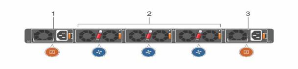
(using breakout cables). The S6000 power supply unit (PSU) side (Figure 2-1) contains the PSU and fan modules.
Figure 2-1. S6000 PSU-Side View
1 - PSU 0
2 - Fan Modules 0-2
3 - PSU 1
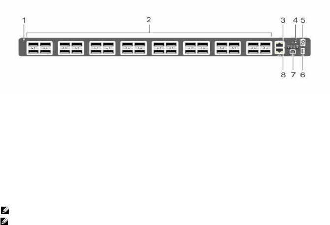
The S6000 input/output (I/O) side (Figure 2-2) includes:
•Thirty-two fixed QSFP+ ports
•One USB 2.0 port
•One USB-B serial console port
•One RS-232 serial console port
•One 10/100/1000BaseT (RJ-45) Ethernet management port
The S6000 Switch |
| |
9 |
w w w . d e l l . c o m | s u p p o r t . d e l l . c o m
Figure 2-2. S6000 I/O-Side View
1 - System LED
2 - 32 QSFP+ Ports
3 - Serial Console
4 - Reset
5 - Stack ID
6 - USB-A
7 - USB-B Console
8 - Management
NOTE: For more information about LEDs, refer the Determine Switch Status section.
NOTE: The system light emitting diodes (LEDs) are on the I/O side. The fan tray power indicators are on the PSU side.
The S6000 switch runs the Dell Networking operating system, providing switching, bridging, and routing functionality for transmitting data, storage, and server traffic.
In a data center network, the S6000 switch provides converged network support and inter-operates with Dell and third-party network devices. The switch supports data center bridging (DCB) features and optimizes connectivity between servers using Fibre Channel over Ethernet (FCoE) and internet small computer system interface (iSCSI) links.
By providing increased 40GbE bandwidth for device interconnection in a shared network storage environment (with the possibility of splitting 40GbE QSFP+ uplinks into four 10GbE SFP+ connections), the S6000 switch is perfectly positioned to help transition a data center with multiple speed requirements.
Features
The S6000 has the following features:
•One universal serial bus (USB-A) port
•One USB-B console port
•Thirty-two 40Gbps QSFP ports for 40Gbps transceivers
•On-board high-performance central processing unit (CPU) system with large memory
10 |
| |
The S6000 Switch |
•Temperature monitoring
•Software-readable thermal monitor
•Real time clock (RTC) support
•Hot-plugging redundant power supply
•Current monitoring for power management
•Removable fan that you can manage
•Standard 1U switch high
Physical Dimensions
The S6000 has the following physical dimensions:
•434 x 460 x 43.5 mm (W x D x H)
•17.09 x 18.11 x 1.71 inches (W x D x H)
Switch Ports
The following is a list of the standard ports located on each S6000 switch:
•Serial RS-232 port (RJ-45 type)
•Out of band (OOB) Ethernet management port (RJ-45 type)
•Thirty-two 40Gbps QSFP+ ports
•One universal serial bus port (USB Type-A)
Determine Switch Status
You can view S6000 status information in several ways, including LEDs and boot menu options. Also, you can view status information through the CLI show commands and with simple network management protocol (SNMP) traps. For more information about these options, refer to the Dell Networking OS Command Line Reference Guide for the S6000 Switch and the Dell Networking OS Configuration Guide for the S6000 Switch.
LED Displays
As shown in Figure 2-3, the S6000 includes LED displays on both the I/O and PSU side of the switch. Table 2-1 through Table 2-3 list the LED definitions for the S6000 switch. This includes the system, PSU, and fan status.
The S6000 Switch |
| |
11 |

w w w . d e l l . c o m | s u p p o r t . d e l l . c o m
Figure 2-3. PSU and Fan Tray LEDs
1- Fan Tray 0-2 LEDs
2 - PSU 0-1 LEDs
1 - Serial Console
2 - Master LED
3 - Power LED
4 - Fan Status LED
5 - Locator LED
6 - Stack ID
7 - USB-A
8 - USB-B Console
9 - Management
12 |
| |
The S6000 Switch |

Table 2-1. System LED Displays
Feature |
Detailed Description |
Comment |
|
|
|
System LED |
• Solid green — Normal operation. The CLI prompt is available. |
I/O side |
|
• Blinking green — Boot-up in progress. |
|
|
• Solid yellow — Major Fault. Displays summary of all major faults |
|
|
within the system; the faults affect traffic. |
|
|
• Blinking yellow — Minor Fault. Displays summary of all minor |
|
|
faults within the system; the faults do not affect traffic. |
|
|
|
|
Power LED |
• Off — No power. |
I/O side |
|
• Solid Yellow — POST in progress. |
|
|
• Solid green — Normal operation (dual or single supply). |
|
|
• Blinking yellow — One of the power supplies has failed. |
|
|
|
|
FAN LED |
• Solid green — Fan powered and running at the expected rpm. |
I/O side |
|
• Solid yellow — Fan failed including incompatible airflow direction |
|
|
when PSU or fan trays of differing airflows are inserted in the same |
|
|
switch. |
|
|
|
|
MASTER LED |
• Solid green — System in stacking Master mode. |
I/O side |
|
• Off — Switch in Slave mode. |
|
|
|
|
LOCATOR LED |
• Off — No power. |
I/O side |
|
• Blinking blue — Locator function is enabled. |
|
|
• Off — Locator function is disabled. |
|
|
|
|
7-DIGIT Stack LED |
• Indicates a number for stacking. |
I/O side |
|
|
|
NOTE: When one of the FAN LEDs on the utility side indicates failure, the fan LED on the I/O panel displays yellow.
The S6000 supports splitting a single 40G QSFP+ port into four 10G SFP+ ports using one of the supported breakout cables. A maximum of 13 ports can be made fanout in each of the ranges from 0 to 63 and from 64 to 127, thereby making the other three ports disabled after reload. You can enable the fanout feature by using the stack-unit port mode command in CONFIGURATION mode.
 Starting with Dell Networking OS version 9.4(0.0), you can configure up to a maximum of one-hundred four10G ports on an S6000.
QSFP+ ports have eight LEDs associated with each stack of two ports; four for the top and four for the bottom ports. You can configure each port as a single 40G port or four 10G ports. When configured as a 40G port, only the first of the four LEDs is used. When configured as four 10G ports, all four LEDs are used to indicate the status. Table 2-2 lists the LED status and Table 2-3 lists the management port LED status.
The S6000 Switch |
| |
13 |

w w w . d e l l . c o m | s u p p o r t . d e l l . c o m
Table 2-2. 40G QSFP+/ 4x10G SFP+ Ethernet Port LEDs
Feature |
Detailed Description |
|
|
Link/Activity LED |
• Off — No Link. |
|
• Blinking green — Transmit/Receive is active. |
|
• Solid green — Link up at 40Gbps/10Gbps speed. |
|
|
Table 2-3. Management Ethernet Port LEDs
Feature |
Detailed Description |
|
|
Link LED |
• Off — No Link. |
|
• Solid green — Link on 10/100M/1G speed. |
|
|
Activity LED |
• Off — No Link. |
|
• Blinking green — Transmit/Receive is active. |
|
|
Basic Installation Requirements
Detailed installation instructions for the S6000 are provided in Chapter 3, Site Location and Preparation and Chapter 4, Install the S6000. However, here is an initial list of components required for a successful installation of the S6000:
•S6000 switch
•If you ordered AC units, cables to connect the AC power source to each of the switch's AC power supplies (country/regional configured)
•If you ordered DC units, cables to connect the DC power source to each of the switch's DC power supplies
•Mounting brackets for rack installation (included)
•Screws for rack installation and #1 and #2 Phillips screwdrivers (not included)
•Ground cable (not included)
•Ground cable screws (included)
•Copper/fiber cables
Optional components for installation:
•Additional power supply units
•Additional fan modules
•Additional mounting brackets (if installing in a 4-post rack or cabinet)
Orderable S6000 Components
You can order the S6000 switch in several different configurations. Also, you can order optional modules and optics separately.
The following is a list of different configurations and modules:
14 |
| |
The S6000 Switch |
•S6000 AC Normal Airflow: Thirty two 40Gbps QSFP+ ports, Two AC power supply and Three fan subsystems (airflow from the I/O side to the PSU side)
•S6000 AC Reverse Airflow: Thirty two 40Gbps QSFP+ ports, Two AC power supply and Three fan subsystems (airflow from the PSU side to the I/O side)
•S6000 AC Normal Airflow: Thirty two 40Gbps QSFP+ ports, Two AC power supply and Three fan subsystems (airflow from the I/O side to the PSU side)
•S6000 AC Reverse Airflow: Thirty two 40Gbps QSFP+ ports, Two AC power supply and Three fan subsystems (airflow from the PSU side to the I/O side)
•Fan with airflow from the I/O side to the PSU side
•Fan with airflow from the PSU side to the I/O side
•AC Power supply with airflow from the I/O side to the PSU side
•AC Power supply with airflow from the PSU side to the I/O side
•DC Power supply with airflow from the I/O side to the PSU side
•DC Power supply with airflow from the PSU side to the I/O side
The S6000 Switch |
| |
15 |
Switch S6000 The | 16
w w w . d e l l . c o m | s u p p o r t . d e l l . c o m

3
Site Location and Preparation
The S6000 is suitable for installation as part of a common bond network (CBN). It can be installed in:
•Network telecommunication facilities
•Data centers
•Other locations where the national electric code (NEC) applies
This chapter contains the following sections regarding where and how you can install the S6000:
•Site Selection
•Cabinet Placement
•Rack Mount
•Ground
•Fans and Airflow
•Power
•Storing Components
NOTE: Install the S6000 switch into a rack or cabinet before installing any optional components.
Site Location and Preparation |
| |
17 |
Loading...