


PowerConnect J-EX4200-48t
Table of contents
 Loading...
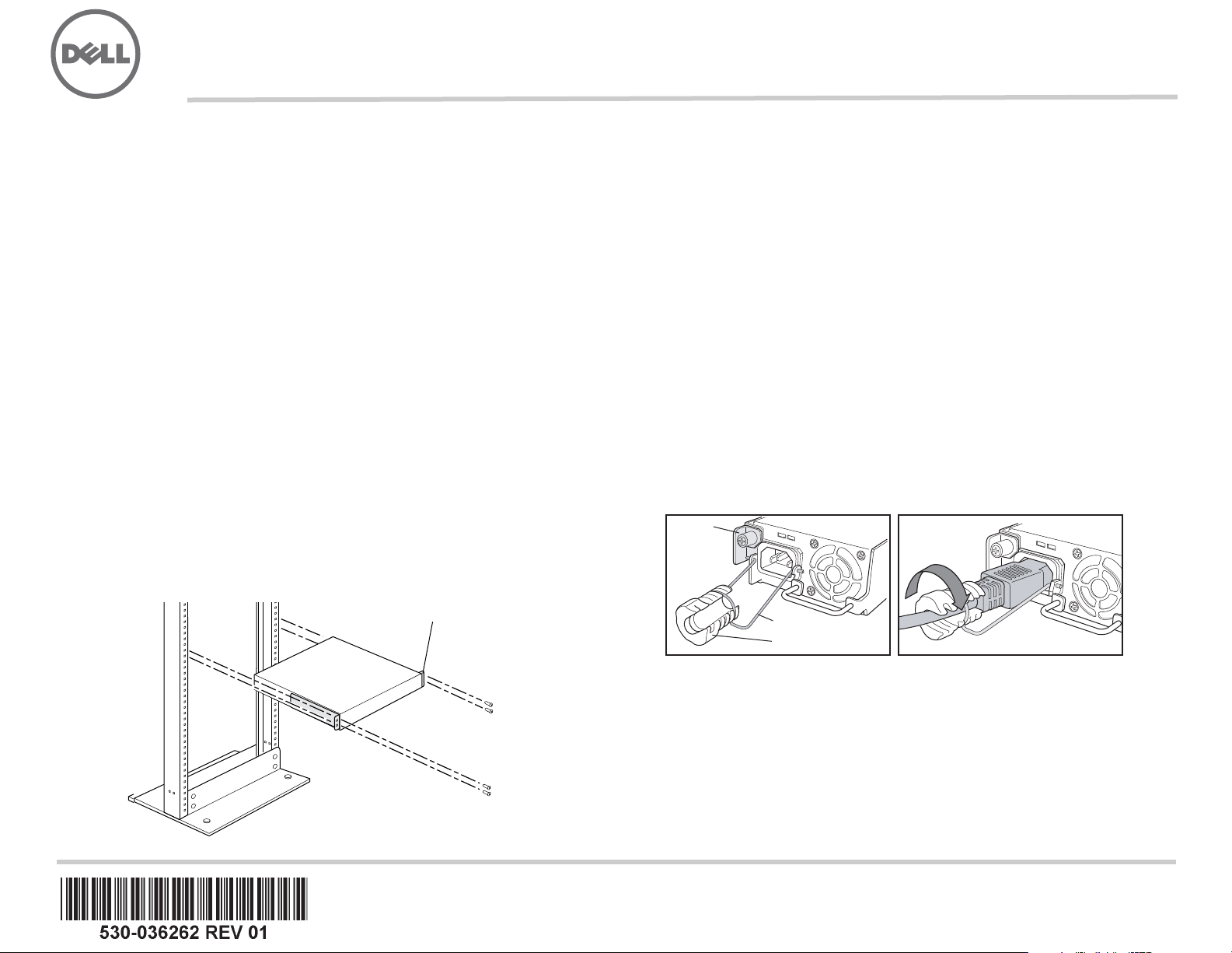
Dell PowerConnect J-Series J-EX4200 Ethernet Switch Quick Start
To install and configure a Dell PowerConnect J-Series J-EX4200 Ethernet Switch
(regulatory model numbers EX4200-24T, EX4200-24F, and EX4200-48T), you need:
z Two mounting brackets and eight mounting screws (provided)
z Phillips (+) screwdriver number 2 to remove and tighten screws
z Hardware to secure the chassis to the rack (provided)
z Jumper cord and cord retainer (provided)
z Grounding cable—minimum 14 AWG (2 mm²), minimum 90°C wire—with Panduit
LCD6-14BH-L grounding lug or equivalent attached by a licensed electrician
z Two 10-32x.25-in. screws with split washers to secure the grounding lug to the switch
z Management host, such as a PC, with an Ethernet port
z Ethernet cable (provided)
NOTE: A Virtual Chassis cable and two cable connector retainers are provided, but their
use is not covered here. These instructions are for two-post rack installation only. For
four-post rack or wall installation, Virtual Chassis configuration, and other tasks, see the
PowerConnect J-EX4200 switch documentation at
http://www/support.dell.com/manuals.
NOTE: Four-post rack-mount and wall-mount kits are available separately.
Part 1: Install a Power Supply in the Switch (If It Is Not Installed)
1. Remove the power supply from the bag. Take care not to touch power supply
components, pins, leads, or solder connections.
2. Push down on the locking lever on the left front of the power supply until it is in its
lowest position (see the figure in Part 4 for the location of the locking lever). You
might need to loosen the locking lever screw to move the lever.
3. Using both hands, place the power supply in the power supply slot on the rear panel
of the switch and slide it in until it is fully seated.
4. Push the locking lever up to its highest position (this action might pull the power
supply in). Tighten the locking lever screw using the screwdriver.
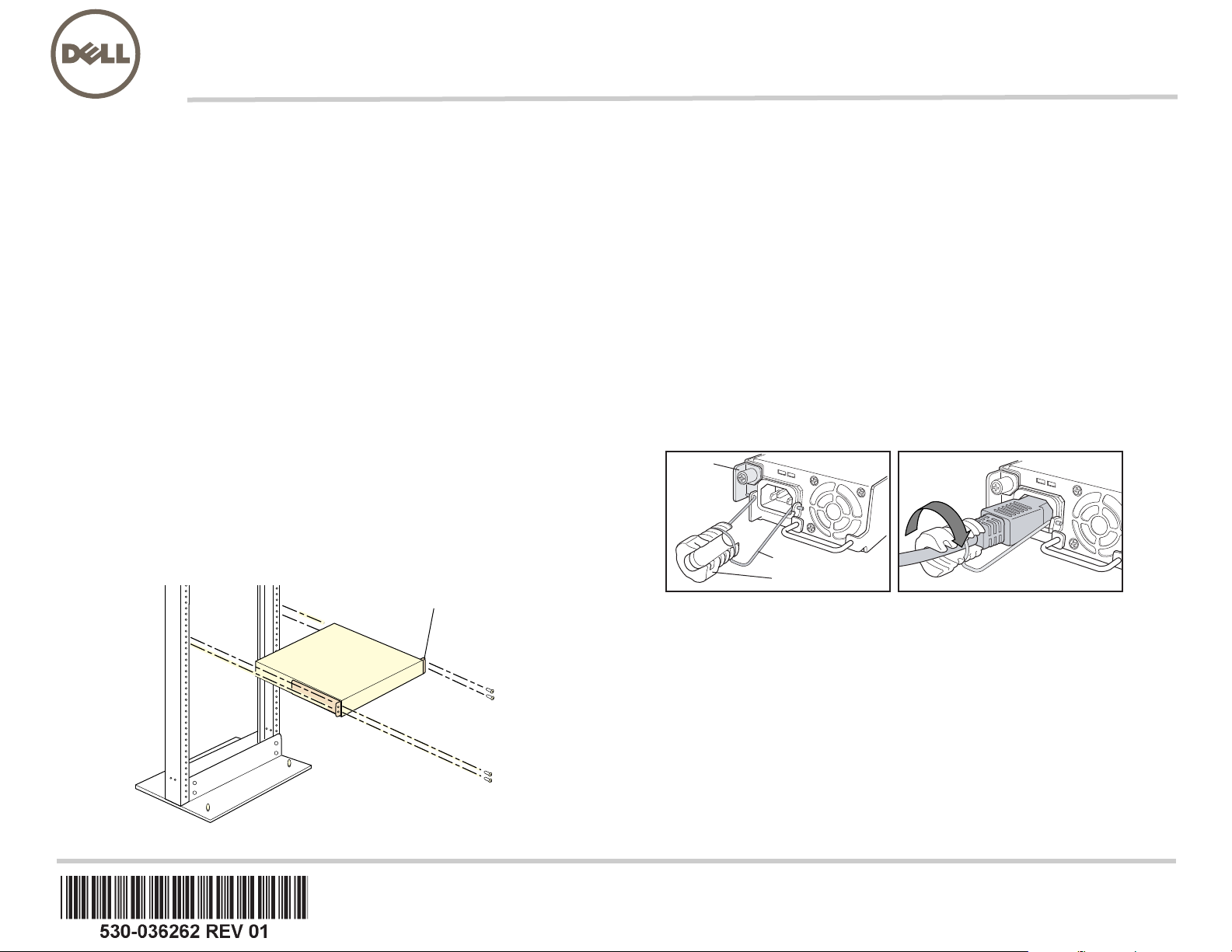
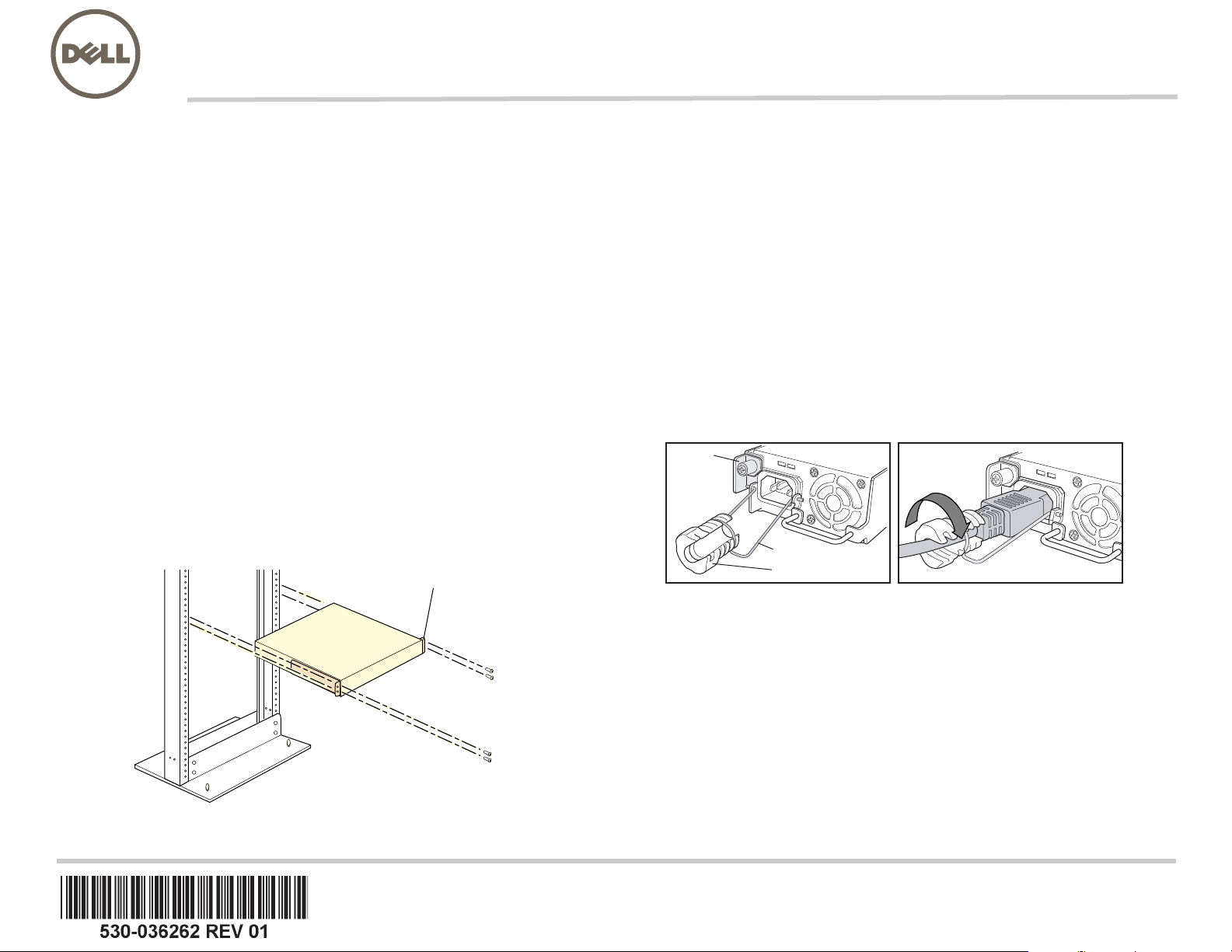
Part 2: Mount the Switch
1. Place the switch on a flat, stable surface.
2. Attach the mounting brackets to the switch chassis with the eight mounting screws.
3. Make sure the rack is properly secured to the building in its permanent location.
4. Have one person grasp both sides of the switch, lift it, and position it in the rack,
aligning the bracket holes with the holes in the rack.
5. Have a second person install a rack-mount screw—and cage nut and washer if your
rack requires them—in each of the four bracket holes to secure the switch to the rack.
Part 3: Connect the Switch to Earth Ground
1. Connect one end of the grounding cable to a proper earth ground, such as the rack in
which the switch is mounted.
2. Place the grounding lug attached to the grounding cable over the protective earthing
terminal on the left side of the chassis, and secure the lug to the terminal with the
screws and washers.
Part 4: Connect AC Power to the Switch
NOTE: If you are interconnecting multiple switches as a Virtual Chassis, power on only
one switch—the one you will use as the master.
1. Squeeze the two sides of the cord retainer clip, and insert the L-shaped ends of the
wire clip into the holes in the bracket on each side of the AC appliance inlet on the
power supply faceplate.
2. Insert the coupler end of the jumper cord into the AC appliance inlet.
3. Push the cord into the slot in the adjustment nut of the cord retainer. Turn the nut until
it is tight against the base of the coupler and the slot in the nut is turned 90° from the
top of the switch.
4. If the AC power source outlet has a power switch, set it to the OFF (0) position.
5. Insert the jumper cord plug into the power source outlet.
6. Repeat these steps for each AC power supply.
7. If the AC power source outlet has a power switch, set it to the ON (|) position.
NOTE: When you connect power to the switch, the Alarm (ALM) LED lights red (major
alarm) to indicate that the network is disconnected. This behavior is normal. Plugging an
active Ethernet cable into the management (MGMT) port on the switch completes the
network link and turns the ALM LED to amber (minor alarm).
The ALM LED turns off when you create a backup rescue configuration.
G
-OUNTINGBRACKET
G
-OUNTINGBRACKET
AC
DC
Locking
lever
Tighten
adjustment nut.
Retainer clip
Adjustment nut
AC
DC
g020063

Information in this document is subject to change without notice. Trademarks used in this text: Dell™, the DELL™ logo, and PowerConnect™ are trademarks of Dell Inc. Juniper Networks® and Junos® are registered trademarks of
Juniper Networks, Inc. in the United States and other countries. All other trademarks, service marks, registered trademarks, or registered service marks are the property of their respective owners. Juniper Networks assumes no
responsibility for any inaccuracies in this document. Juniper Networks reserves the r ight t o change, modif y, transfer, or oth erwise re vi se th is p ublication with out not ice. Pro ducts made or sold by Juniper Networks or components thereof
might be covered by one or more of the following patents that are owned by or licensed to Juniper Networks: U.S. Patent Nos. 5,473,599, 5,905,725, 5,909,440, 6,192,051, 6,333,650, 6,359,479, 6,406,312, 6,429,706, 6,459,579,
6,493,347, 6,538,518, 6,538,899, 6,552,918 , 6,567,902, 6,578,186, and 6,590,785.
Copyright © 2010, Juniper Networks, Inc. All rights reserved. Reproduction of these materials in any manner whatsoever without the written permission of Juniper Networks is strictly forbidden. Printed in USA.
Juniper Networks Part Number: 530-06262. Revision 01, 15 August 2010.
Part 5: Perform Initial Configuration
NOTE: To obtain an IP address dynamically, you must enable a DHCP client on the
management PC you connect to the switch.
NOTE: Read the following steps before you begin the configuration. Complete the initial
configuration using EZSetup within 10 minutes. The LCD panel displays a count-down
timer when the switch is in initial setup mode. The switch exits EZSetup after 10 minutes
and reverts to the factory configuration, and the PC loses connectivity to the switch.
1. Transition the switch into initial setup mode using the Menu and Enter buttons to the
right of the LCD panel. To do this:
− Press Menu until you see MAINTENANCE MENU. Then press Enter.
− Press Menu until you see ENTER EZSetup. Then press Enter .
If EZSetup does not appear as an option in the me nu , select Factory Default to
return the switch to the factory default configuration. EZSetup is displayed in the
menu only when the switch is set to the factory default configuration.
− Press Enter to confirm setup and continue with EZSetup.
2. Connect the Ethernet cable from the Ethernet port on the PC to port 0 (ge-0/0/0) on
the front panel of the switch.
The ge-0/0/0 interface is now configured as the DHCP server with the default IP
address,
192.168.1.1. The switch can assign an IP address to the management PC
in the IP address range
192.168.1.2 through 192.168.1.253.
3. From the PC, open a Web browser, type http://192.168.1.1 in the address field, and
press the Enter key.
4. On the J-Web Login page, enter root as the username, leave the password field
blank, and click Login.
5. On the Introduction page, click Next.
6. On the Basic Settings page, enter the hostname, enter and reenter a password,
specify the time zone, and synchronize the switch date and time settings with the
management PC or set them manually.
7. Click Next.
8. Use the Management Options page to select the management scenario:
− In-band Management—Use VLAN ‘default’ for management
Select this option to configure all data interfaces as members of the default VLAN.
Click Next. Specify the management IP address and the default gateway.
− In-band Management—Create new VLAN for management
Select this option to create a management VLAN. Click Next. Specify the VLAN
name, VLAN ID, member interfaces, and management IP address and default
gateway for the new VLAN.
− Out-of-band Management—Configure management port
Select this option to configure only the management interface. Click Next. Specify
the IP address and default gateway for the management interface.
9. Click Next.
10. On the Manage Access page, you may select options to enable Telnet, SSH, and
SNMP services. For SNMP, you can configure the read community, location, and
contact.
11. Click Next. The Summary page displays the settings you have selected.
12. Click Finish. The configuration is committed as the active switch configuration. You
can now log in with the CLI or the J-Web interface to continue configuring the switch.
NOTE: After the configuration is committed, the connectivity between the PC and the
switch might be lost. To reconnect, release and renew the IP address by executing the
appropriate commands on the PC or by removing and reinserting the Ethernet cable.
Safety Warnings Summary
This is a summary of safety warnings. For a complete list of warnings, including
translations, see the see the PowerCon nect J-EX4200 switch documentation at
http://www.suppport.dell.com/manuals.
WARNING: Failure to observe these safety warnings can result in personal injury
or death.
z Permit only trained and qualified personnel to install or replace switch components.
z Perform only the procedures described in this quick start and the J-EX4200 switch
documentation. Only authorized service personnel must perform other services.
z Before installing the switch, read the planning instructions in the J-EX4200 switch
documentation to make sure that the site meets power, environmental, and clearance
requirements for the switch.
z Before connecting the switch to a power source, read the installation instructions in the
J-EX4200 switch documentation.
z A fully loaded J-EX4200 switch weighs approximately 22 lb (10 kg). Manually installing
the switch in a rack requires one person to lift the switch and a second person to install
mounting screws. To prevent injury, keep your back straight and lift with your legs, not
your back.
z If the rack has stabilizing devices, install them in the rack before mounting or servicing
the switch in the rack.
z Before installing or after removing an electrical component, always place it
component-side up on a flat antistatic surface or in an electrostatic bag.
z Do not work on the switch or connect or disconnect cables during electrical storms.
z Before working on equipment that is connected to power lines, remove jewelry,
including rings, necklaces, and watches. Metal objects heat up when connected to
power and ground and can cause serious burns or become welded to the terminals.
Power Cable Warning (Japanese)
The power cable is only for this product. Do not use the cable for another product.
Contacting Dell Inc.
For technical support, see http://www.support.dell.com.
g040300
Dell PowerConnect J 系列 J-EX4200 乙太網路交換機快速入門
若要安裝及組態 「Dell PowerConnect J 系列 J-EX4200 乙太網路交換機」 (
管理型號為
EX4200-24T
、
EX4200-24F
與
EX4200-48T),您需要 :
z 2 個裝載托架和 8 個裝載螺絲 ( 已提供 )
z 用於鬆開和旋緊螺絲的 2 號十字 (+) 螺絲起子
z 用於將機箱固定在機架上的硬體 ( 已提供 )
z 跳線與跳線固定器 ( 已提供 )
z 接地纜線—最小 14 AWG (2 mm²),最小 90°C 的電線—由授權電工將纜線與 Panduit
LCD6-14BH-L 接地接線片或同型接線片連接
z 用於將接地接線片固定至交換機的兩顆 10-32x.25-in. 螺絲與開口墊圈
z 管理含乙太網路連接埠的主機,如 PC
z 乙太網路纜線 ( 已提供 )
注意: 提供一條 「虛擬機箱」纜線和兩個纜線連接器固定器,但此處不會說明其使用方
式。以下說明僅適用於雙柱式機架的安裝。如需四柱式機架或牆上安裝、「虛擬機箱」組
態和其他工作的資訊,請參閱 PowerConnect J-EX4200 交換機文件,網址為
http://www/support.dell.com/manuals。
注意: 四柱式機架裝載套件與牆上裝載套件分別提供。
第 1 部分:在交換機中安裝電源供應器 ( 若尚未安裝 )
1. 從袋子中取出電源供應器。注意不要碰到電源供應器元件、接腳、導線或焊錫連
接處。
2. 將電源供應器左前方的鎖定桿向下拉,直到其最低位置為止 ( 請參閱 「第 4 部分」中
的圖,來查看鎖定桿的位置 )。您可能需要鬆開鎖定桿螺絲,才能移動鎖定桿。
3. 用兩隻手將電源供應器放到交換機後面板上的電源供應器插槽中,然後將其滑入,直
到完全固定住為止。
4. 向上推動鎖定桿,直到其最高位置為止 ( 此動作可能會將電源供應器拉進去 )。使用
螺絲起子鎖緊鎖定桿的螺絲。
第 2 部分:安裝交換機
1. 將交換機放置在平坦且穩固的表面上。
2. 使用 8 個裝載螺絲將裝載托架連接至交換機機箱。
3. 確保將機架正確固定至其在建築物上的永久位置。
4. 讓一個人握住交換機的兩側抬起交換機,然後將其放在機架中,使托架孔與機架孔
對齊。
5. 讓另一個人將機架裝載螺絲 ( 機架需要時可使用鎖緊螺帽和墊圈 ) 安裝於四個機架
孔,以將交換機固定至機架。
第 3 部分:將交換機連接至地面
1. 將接地纜線的一端適當接地,例如裝載交換機的所在機架。
2. 將連接接地纜線的接地接線片置於機箱左側的保護接地終端,然後使用螺絲和墊圈將
接線片固定到終端。
第 4 部分:將 AC 電源連接至交換機
注意: 如果要將多個交換機互連在一起作為 「虛擬機箱」,則只能開啟一個交換機的電
源,即要作為主裝置使用的交換機的電源。
1. 擠壓電源纜線固定夾的兩側,將接線夾的 L 形端點插入至電源供應器面板上 AC 設備
插座兩側托架上的插孔中。
2. 將跳線的耦合器端插入至 AC 設備插座中。
3. 將電源纜線推入電源纜線固定器調整螺帽的插槽中。旋轉螺帽,直到其牢牢固定在耦
合器基座上為止,且螺帽中的插槽已從交換機頂部旋轉 90°。
4. 如果 AC 電源插座有電源開關,請將其設定為 OFF (0) 位置。
5. 將跳線插頭插入至電源插座中。
6. 對每個 AC 電源供應器都重複這些步驟。
7. 如果 AC 電源插座有電源開關,請將其設定為 ON (|) 位置。
注意: 將電源連接至交換機時,紅色 Alarm (ALM) LED 指示燈 ( 重要警示 ) 表示網路未連
線。
此為正常行為。
將作用中的乙太網路纜線插入交換機上的管理 (MGMT) 連接埠以完
成網路連結,而 ALM LED 會轉為琥珀黃色 ( 輕微警示 )。
建立備份救援組態時,會關閉 ALM LED。
J
孬憘㓧㩅
AC
DC
春⸩㬎 㝿偙
嵎㠃婉ヌᇭ
⦉⸩⯍
嵎㠃婉ヌ
AC
DC
g020063

本文件中的資訊如有變更,恕不另行通知。 本文中所使用的商標: Dell™、DELL™ 標誌和 PowerConnect™ 為 Dell Inc. 的商標。Juniper Networks® 和 Junos® 為 Juniper Networks, Inc. 在美國與其他國家 / 地區的註冊商標。 所有其他
商標、服務標記、註冊商標或註冊服務標記都屬於其個別擁有者的財產。 Juniper Networks 對本文件中的任何錯誤,不承擔任何責任。 Juniper Networks 保留對本出版物進行變更、修改、轉印或其他修訂而不另行通知的權利。
Juniper Networks 製造或銷售的產品或其中的元件可能涵蓋於下列一或多個由 Juniper Networks 所有或 Juniper Networks 已獲授權的專利: 美國專利號 5,473,599、5,905,725、5,909,440、6,192,051、6,333,650、6,359,479、
6,406,312、6,429,706、6,459,579、6,493,347、6,538,518、6,538,899、6,552,918、6,567,902、6,578,186 和 6,590,785。
版權所有 © 2010,Juniper Networks, Inc. 保留所有權利。 未經 Juniper Networks 書面許可,嚴格禁止以任何方式複製這些資料。 美國印刷。
Juniper Networks 產品編號: 530-036262-ZH-HANT. 修訂本 01,2010 年 8 月 15 日
。
第 5 部分:執行初始組態
注意: 若要動態獲取 IP 位址,必須在連接至交換機的管理 PC 上啟用 DHCP 用戶端。
注意: 在開始組態之前,請先閱讀以下步驟。使用 EZSetup 在 10 分鐘內完成初始組態。
交換機處於初始設定模式時,LCD 面板會顯示倒數計時器。交換機在 10 分鐘後會退出
EZSetup,然後便會回復為出廠組態,同時 PC 會失去與交換機的連線。
1. 使用 LCD 面板右側的 Menu 與 Enter 按鈕,將交換機轉變為初始設定模式。若要進
行此操作:
− 按 Menu,直到看見 MAINTENANCE MENU 為止。然後按 Enter。
− 按 Menu,直到看見 ENTER EZSetup 為止。然後按 Enter。
若 EZSetup 未顯示為功能表中的選項,請選擇 Factory Default 將交換機恢復為出
廠預設組態。只有在交換機設定為出廠預設組態之後,才會在功能表中顯示
EZSetup。
− 按 Enter 確認設定,然後繼續執行 EZSetup。
2. 將乙太網路纜線從 PC 上的乙太網路連接埠,連接至交換機前面板上的連接埠 0
(
ge-0/0/0)。
ge-0/0/0 介面現會組態為 DHCP 伺服器,其預設 IP 位址為 192.168.1.1。交換機可以
將
192.168.1.2 到 192.168.1.253 之間的 IP 位址指派給管理 PC。
3. 從 PC 中,開啟 Web 瀏覽器,在位址欄位中鍵入 http://192.168.1.1,然後按
Enter 鍵。
4. 在 J-Web 登入 頁面上,輸入 root 作為使用者名稱,將密碼欄位保留空白,然後按一
下 Login。
5. 在 Introduction 頁面上,按一下 Next。
6. 在 Basic Settings 頁面上,輸入主機名稱、輸入密碼、再次輸入密碼、指定時區,然
後將交換機的日期與時間設定與管理 PC 同步化,或是進行手動設定。
7. 按一下 Next。
8. 使用 Management Options 頁面,選擇管理方案 :
− In-band Management—Use VLAN ‘default’ for management
選擇此選項可將所有資料介面組態為預設 VLAN 的成員。按一下 Next。指定管理
IP 位址與預設閘道。
− In-band Management—Create new VLAN for management
選擇此選項可建立管理 VLAN。按一下 Next。為新 VLAN 指定 VLAN 名稱、
VLAN ID、成員介面、管理 IP 位址以及預設閘道。
− Out-of-band Management—Configure management port
選擇此選項可以僅組態管理介面。按一下 Next。指定管理介面的 IP 位址與預設
閘道。
9. 按一下 Next。
10. 在 Manage Access 頁面上,可以選擇選項來啟用 Telnet、SSH 與 SNMP 等服務。可
以針對 SNMP 組態讀取社群、位置與聯絡資訊。
11. 按一下 Next。Summary 頁面會顯示已選擇的設定。
12. 按一下 Finish。組態已認可,並作為活動中的交換機組態。現在,可以使用 CLI 或
J-Web 介面登入來繼續組態交換機。
注意: 在認可組態後,可能會失去 PC 與交換機之間的連線。若要重新連線,請在 PC 上
執行適當的指令,或拔下乙太網路纜線然後重新插入,以釋放及更新 IP 位址。
安全警告摘要
這是安全警告摘要。如需完整警告清單 ( 含解釋 ),請參閱 PowerConnect J-EX4200 交
換機文件,網址為
http://www.support.dell.com/manuals。
警告: 若未能注意到這些安全警告,可能會導致人身傷害或死亡。
z 只有受過訓練的合格人員才能安裝或更換交換機元件。
z 請僅執行此快速入門與 J-EX4200 交換機文件中所述的步驟。只有授權的服務人員才能
執行其他服務。
z 在安裝交換機之前,請先閱讀 J-EX4200 交換機文件中的計劃說明,確保場地符合交換
機的電源、環境和周圍空間需求。
z 在將交換機連接至電源之前,請先閱讀 J-EX4200 交換機文件中的安裝說明。
z 完整裝載的 J-EX4200 交換機重量約為 22 磅 (10 公斤 )。手動將交換機安裝到機架時,
需要一個人抬起交換機,另一個人安裝裝載螺絲。為了避免受傷,請將背部挺直並用腿
部力量抬起,而不是靠背部力量。
z 若機架配有穩定裝置,請先將其安裝到機架上,然後再裝載或維修機架中的交換機。
z 安裝電氣元件之前或移除電氣元件之後,請務必讓元件面朝上,並放在平坦的防靜電表
面或靜電袋中。
z 在電暴期間,請勿使用交換機,或連接或中斷連接纜線。
z 在使用連接至電源線的設備之前,請先取下首飾,包括戒指、項鍊和手錶。當連接到電
源或接地時,金屬物件會變熱,可能會導致嚴重灼傷或與終端相熔接。
電源線警告 ( 日文 )
此電源線只可用於本產品。請勿將纜線用於其他產品。
請與 Dell Inc 聯絡。
如需技術支援,請造訪 http://www.support.dell.com。
g040300
Dell PowerConnect J 系列 J-EX4200 以太网交换机快速入门
要安装和配置 Dell PowerConnect J 系列 J-EX4200 以太网交换机 (
规范型号为
EX4200-24T
、
EX4200-24F
与
EX4200-48T),需要 :
z 2 个安装托架和 8 个安装螺钉 (提供)
z 2 号十字 (+) 螺钉起子,用于卸下和拧紧螺钉
z 用于将机箱固定在机架上的硬件 (提供)
z 跳接线与接线器 (提供)
z 接地电缆—最小 14 AWG (2 mm²),最小 90°C 的电线—由授权电工将电缆与 Panduit
LCD6-14BH-L 接地片或同型接线片连接
z 用于将接地片固定至交换机的两颗 10-32x.25-in. 螺钉与开口垫圈
z 具有以太网端口的管理主机 (例如 PC)
z 以太网电缆 (提供)
注意: 提供一条虚拟机箱电缆和两个电缆连接器接线器,但此处不会说明其使用方式。以
下说明仅适用于双柱式机架的安装。有关四柱式机架或墙上安装、虚拟机箱配置和其他任
务的信息,请参阅 PowerConnect J-EX4200 交换机文档,网址为
http://www/support.dell.com/manuals。
注意: 四柱式机架安装套件与墙上安装套件分别提供。
第 1 部分:在交换机中安装电源 (若尚未安装)
1. 从袋中取出电源。注意不要碰到电源组件、针脚、导线或焊接处。
2. 将电源左前方的锁定杆向下拉,直到其最低位置为止 (请参阅第 4 部分中的图查看锁
定杆的位置 )。可能需要松开锁定杆螺钉,才能移动锁定杆。
3. 用两只手将电源放到交换机后面板上的电源插槽中,然后将其滑入,直到完全固定住
为止。
4. 向上推动锁定杆,直到其最高位置为止 (此动作可能会将电源拉进去)。使用螺钉起
子拧紧锁定杆的螺钉。
第 2 部分:安装交换机
1. 将交换机置于平整、稳定的平面上。
2. 使用八个安装螺钉将安装托架安装到交换机机箱。
3. 请确保机架在其固定位置与建筑物牢牢固定。
4. 由一个人紧握交换机两侧,将其抬起并放入机架中,并使托架孔与机架孔对齐。
5. 让另一个人将机架安装螺钉 (机架需要时可使用卡式螺母和垫圈)安装于四个机架
孔,以将交换机固定至机架。
第 3 部分:将交换机接地
1. 将接地电缆的一端适当接地,例如安装交换机的所在机架。
2. 将连接接地电缆的接地片置于机箱左侧的保护性接地端子上,然后使用螺钉和垫圈将
接线片固定到端子。
第 4 部分:将 AC 电源连接至交换机
注意: 如果要将多个交换机互连在一起作为虚拟机箱,则只能开启一个交换机的电源,即
要作为主设备使用的交换机的电源。
1. 挤压接线夹的两侧,将接线夹的 L 形端点插入至电源面板上 AC 设备插座两侧托架上
的插孔中。
2. 将跳接线的耦合器端插入 AC 设备插座。
3. 将电源线推入接线器调整螺母的插槽中。旋转螺母,直到其牢牢顶到耦合器的底座,
而且螺母中的插槽从交换机顶部旋转 90°。
4. 如果 AC 电源插座具有电源开关,请将其设置到 OFF (0) 位置。
5. 将跳接线插头插入电源插座。
6. 对每个 AC 电源均重复这些步骤。
7. 如果 AC 电源插座具有电源开关,请将其设置到 ON (|) 位置。
注意: 将电源连接至交换机时,红色 报警 (ALM) LED 指示灯 (重要警告)表示网络未联
机。
此为正常行为。
将作用中的以太网电缆插入交换机上的管理 (MGMT) 端口以完成网
络链接,而 ALM LED 会转为琥珀黄色 (轻微警示)。
创建备份救援配置时, ALM LED 会关闭。
J
⸘孔㓧㩅
AC
DC
析⸩㧕
㕶侶
庒㠃婉㹜ᇭ
㘴兎⯈
庒㠃婉㹜
AC
DC
g020063

本文档中的信息如有更改,恕不另行通知。 本文中使用的商标:Dell™、 DELL™ 标志和 PowerConnect™ 为 Dell Inc. 的商标。 Juniper Networks® 和 Junos® 为 Juniper Networks, Inc. 在美国与其他国家 / 地区的注册商标。 所有其他商
标、服务标志、注册商标或注册服务标志均属其各自所有者的资产。 Juniper Networks 对本文档中的任何错误不承担任何责任。 Juniper Networks 保留变更、修改、转印或另外修订本出版物而不另行通知的权利。 Juniper Networks 制造
或销售的产品或者相关组件可能受到以下 Juniper Networks 拥有或得到授权的一项或多项专利的保护: 美国专利编号 5,473,599、 5,905,725、 5,909,440、 6,192,051、 6,333,650、 6,359,479、 6,406,312、 6,429,706、 6,459,579、
6,493,347、 6,538,518、 6,538,899、 6,552,918、 6,567,902、 6,578,186 和 6,590,785。
版权所有 © 2010, Juniper Networks, Inc. 保留所有权利。 未经 Juniper Networks 书面许可,严禁以任何方式复制这些材料。 美国印刷。
Juniper Networks 产品编号:530-036262-ZH-HANS. 修订本 01, 2010 年 8 月 15 日
。
第 5 部分:执行初始配置
注意: 要动态获取 IP 地址,必须在连接至交换机的管理 PC 上启用 DHCP 客户端。
注意: 开始配置之前请阅读以下步骤。使用 EZSetup 在 10 分钟之内完成初始配置。交换
机处于初始设置模式时, LCD 面板会显示倒数计时器。交换机在 10 分钟后会退出
EZSetup,然后便会恢复为出厂配置,同时 PC 会失去与交换机的连接。
1. 使用 LCD 面板右侧的 Menu 和 Enter 按钮将交换机转换到初始设置模式。要执行此
操作:
− 按 Menu,直到显示 MAINTENANCE MENU。然后按 Enter。
− 按 Menu,直到显示 ENTER EZSetup。然后按 Enter。
如果 EZSetup 未显示为菜单中的选项,请选择 Factory Default 将交换机恢复为出
厂缺省配置。只有将交换机设置为出厂缺省配置,菜单中才会显示 EZSetup。
− 按 Enter 确认设置并继续 EZSetup 操作。
2. 将以太网电缆从 PC 上的以太网端口连接至交换机前面板上的端口 0 (ge-0/0/0)。
ge-0/0/0 接口现会配置为 DHCP 服务器,其缺省 IP 地址为 192.168.1.1。交换机可以
将
192.168.1.2 到 192.168.1.253 之间的 IP 地址分配给管理 PC。
3. 在 PC 上打开 Web 浏览器,在地址字段中键入 http://192.168.1.1,然后按 Enter 键。
4. 在 J-Web 登录 页面上,输入 root 作为用户名,将密码字段保留空白,然后按一下
Login。
5. 在 Introduction 页面中单击 Next。
6. 在 Basic Settings 页面上输入主机名、输入并再次输入密码、指定时区,然后使交换
机日期和时间与管理 PC 同步或对交换机时间和日期进行手动设置。
7. 单击 Next。
8. 使用 Management Options 页面,选择管理方案 :
− In-band Management—Use VLAN ‘default’ for management
选择此选项可将所有数据接口配置为缺省 VLAN 的成员。单击 Next。指定管理 IP
地址与缺省网关。
− In-band Management—Create new VLAN for management
选择此选项可创建管理 VLAN。单击 Next。为新的 VLAN 指定 VLAN 名称、
VLAN ID、成员接口和管理 IP 地址以及缺省网关。
− Out-of-band Management—Configure management port
选择此项以仅配置管理接口。单击 Next。指定管理接口的 IP 地址和缺省网关。
9. 单击 Next。
10. 在 Manage Access 页面上,您可以选择启用 Telnet、 SSH 和 SNMP 服务的选项。对
于 SNMP,您可配置读取公共组、位置和联系。
11. 单击 Next。 Summary 页面将显示您所选择的设置。
12. 单击 Finish。该配置已成功设置为活动交换机配置。您现在可使用 CLI 或 J-Web 接
口登录,以继续对交换机进行配置。
注意: 完成配置后, PC 与交换机之间的连接可能会断开。要重新连接,可通过对 PC 执
行相应的命令或拔掉并重新插上以太网电缆来释放并更新 IP 地址。
安全警告汇总
本部分为安全警告的汇总。如需完整警告列表 (含解释),请参阅 PowerConnect
J-EX4200 交换机文档,网址为
http://www.support.dell.com/manuals。
警告:违反这些安全警告可能会造成人身伤害或死亡。
z 只允许经过培训并取得资格认证的人员安装或更换交换机组件。
z 只可以执行本快速入门及 J-EX4200 交换机文档中所介绍的操作。只有授权的服务人员
才能执行其他服务。
z 在安装交换机之前,请阅读 J-EX4200 交换机文档中的规划说明,以确保安装场所符合
交换机的电源、环境和空间要求。
z 交换机接通电源之前,请阅读 J-EX4200 交换机文档中的安装说明。
z 安装全部组件后的 J-EX4200 交换机重量约为 22 磅 (10 公斤 )。手动将交换机安装到机
架时,需要一个人抬起交换机,另一个人安装安装螺钉。为防止受伤,请将后背挺直,
用腿而不是后背的力量来抬设备。
z 如果机架具有稳定装置,请首先安装这些装置,然后再在机架中安装或维修交换机。
z 在安装电子组件之前或将电子组件卸下之后,请务必让组件一侧朝上,并将其放置在平
坦的防静电表面上或静电袋中。
z 切勿在雷暴期间对开关进行操作或者连接 / 断开电缆。
z 在操作连接到电源线的设备之前,请先摘下珠宝饰物,包括戒指、项链和手表。金属体
在连接到电源和地面时会发热,可能会导致严重的烧焦或与接线端相熔接。
电源线警告 (日语)
电源线只适用于本产品。请勿将此电源线用于其他产品。
请联系 Dell Inc.
要获取技术支持,请访问 http://www.support.dell.com。
g040300

Commutateur Ethernet Dell PowerConnect J-Series J-EX4200 -
Guide de mise en route
Pour installer et configurer un commutateur Ethernet Dell PowerConnect J-Series J-EX4200
(
numéros de modèle réglementaires EX4200-24T, EX4200-24F et EX4200-48T
), vous
avez besoin des accessoires suivants :
z Deux supports de montage et huit vis de montage (fournis)
z Tournevis cruciforme (+) n° 2 pour retirer et serrer les vis
z Vis pour fixer solidement le châssis à la baie (fournies)
z Un câble de raccordement et son clip de fixation (fournis)
z Un câble de mise à la terre — 14 AWG minimum (2 mm²), fil résistant à 90 °C
minimum
— avec œillet de mise à la terre Panduit LCD6-14BH-L ou équivalent fixé
par un électricien professionnel
z Deux vis 10-32x0,25 po. avec rondelles élastiques pour fixer l’œillet de mise à la terre
au commutateur
z Un hôte de gestion, tel qu’un ordinateur, doté d’un port Ethernet
z Un câble Ethernet (fourni)
REMARQUE : un câble Virtual Chassis et deux clips de fixation de connecteur de câble
sont fournis, mais leur utilisation n’est pas décrite ici. Les présentes instructions ne
concernent que les installations dans une baie à deux montants. Pour obtenir les
instructions d’une installation à quatre montants ou murale, la configuration Virtual
Chassis et d’autres tâches, consultez la documentation du commutateur PowerConnect
J-EX4200 sur le site Internet http://www/support.dell.com/manuals.
REMARQUE : les kits de montage en baie à quatre montants ou muraux sont
disponibles séparément.
Partie 1 : Installation du bloc d’alimentation du commutateur (si nécessaire)
1. Sortez le bloc d’alimentation de son emballage. Veillez à ne pas toucher les
composants, broches, fils ou connexions soudées du bloc d’alimentation.
2. Sur la partie avant gauche du bloc d’alimentation, abaissez le levier de verrouillage
en position inférieure (voir la figure proposée à la partie 4 pour le repérer). Pour
libérer ce levier et le déplacer, vous devrez éventuellement desserrer sa vis.
3. Manipulez le bloc d’alimentation à deux mains. Déposez-le dans son emplacement à
l’arrière du commutateur et faites-le glisser jusqu’à ce qu’il soit correctement installé.
4. Relevez le levier de verrouillage en position supérieure (cela peut repousser le bloc
d’alimentation). Resserrez la vis du levier à l’aide d’un tournevis.
Partie 2 : Montage du commutateur
1. Posez le commutateur sur une surface plane et stable.
2. Fixez les supports de montage au châssis du commutateur à l’aide des huit vis de
montage.
3. Vérifiez que la baie est solidement fixée dans son local d’installation définitif.
4. Une première personne doit saisir le commutateur par ses deux côtés, le soulever et
le placer dans la baie, en alignant les trous des supports sur les trous de la baie.
5. Une deuxième personne doit installer une vis de montage en baie — ainsi qu’un
écrou à cage et une rondelle si la baie les requiert — dans chacun des quatre trous
des supports pour fixer solidement le commutateur à la baie.
Partie 3 : Raccordement du commutateur à la terre
1. Connectez une extrémité du câble de mise à la terre à une terre correcte, telle que la
baie dans laquelle le commutateur est monté.
2. Placez l’œillet de mise à la terre fixé au câble de mise à la terre sur la borne de mise
à la terre de protection du côté gauche du châssis, puis fixez l’œillet à la borne avec
les vis et les rondelles.
Partie 4 : Raccordement du commutateur à une source d’alimentation en courant
alternatif (CA)
REMARQUE : si vous interconnectez plusieurs commutateurs en tant que système
Virtual Chassis, ne mettez sous tension qu’un seul commutateur (celui jouant le rôle de
maître).
1. Appuyez sur les deux côtés du clip de fixation du câble et insérez les fiches en L du
clip dans les trous du support de chaque côté du connecteur d’alimentation CA sur la
façade du bloc d’alimentation.
2. Branchez la fiche de couplage du câble de raccordement sur le connecteur
d’alimentation CA.
3. Poussez le câble dans le logement qui lui est réservé dans l’écrou de réglage du clip
de fixation. Serrez bien l’écrou contre la base du système de couplage, l’ouverture de
son logement intérieur étant tournée à 90° par rapport à la face du dessus du
commutateur.
4. Si la prise électrique CA est dotée d’un interrupteur, mettez ce dernier en position
d’arrêt (OFF - 0).
5. Branchez le câble de raccordement sur la prise électrique.
6. Répétez cette procédure sur chaque bloc d’alimentation CA.
7. Si la prise électrique CA est dotée d’un interrupteur, mettez ce dernier en position de
marche (ON - |).
REMARQUE : lorsque vous connectez le commutateur à une source d’alimentation
électrique, les LED d’alarme (ALM) s’allument en rouge (alarme majeure) pour indiquer
que le réseau est déconnecté. Ce comportement est normal. Le branchement d’un câble
Ethernet actif dans le port de gestion (MGMT) du commutateur complète la liaison
réseau et allume la LED ALM en orange (alarme mineure).
La LED ALM s’éteint lorsque vous créez une configuration de sauvegarde.
G
-OUNTINGBRACKET
G
-OUNTINGBRACKET
J
6XSSRUWGHPRQWDJH
CA
CC
Levier de
verrouillage
Serrer l’écrou
de réglage.
Clip de fixation
Écrou de réglage
CA
CC
g020063

Les informations présentées dans ce document sont susceptibles d’être modifiées sans avis préalable. Dans le présent texte, Dell™, le logo DELL™ et PowerConnect™ sont des marques commerciales de Dell Inc. Juniper Networks® et
Junos® sont des marques déposées de Juniper Networks, Inc. aux États-Unis et dans d’autres pays. Toutes les autres marques commerciales, marques de service, marques déposées ou marques de service déposées sont la propriété de
leurs détenteurs respectifs. Juniper Networks décline toute responsabilité quant à la présence éventuelle d’imprécisions dans ce document. Juniper Networks se réserve le droit de modifier, transférer ou réviser de toute autre manière cette
publication sans préavis. Les produits fabriqués ou vendus par Juniper Networks ou les composants de ces produits peuvent être protégés par l’un ou plusieurs des brevets suivants qui appartiennent à Juniper Networks ou font l’objet d’une
licence Juniper Networks : n° de brevets aux États-Unis : 5,473,599, 5,905,725, 5,909,440, 6,192,051, 6,333,650, 6,359,479, 6,406,312, 6,429,706, 6,459,579, 6,493,347, 6,538,518, 6,538,899, 6,552,918, 6,567,902, 6,578,186 et 6,590,785.
Copyright © 2010, Juniper Networks, Inc. Tous droits réservés. Toute reproduction de ces matériaux, quelle que soit la méthode utilisée, est formellement interdite sans l’accord écrit préalable de Juniper Networks. Imprimé aux
États-Unis.
Référence Juniper Networks : 530-036262-FR. Révision 01, 15 août 2010.
Partie 5 : Exécution de la configuration initiale
REMARQUE : pour obtenir une adresse IP de manière dynamique, vous devez activer
un client DHCP sur l’ordinateur de gestion auquel le commutateur est relié.
REMARQUE : avant de commencer la configuration, lisez la totalité de la procédure
suivante. Vous disposez de 10 minutes pour procéder à la configuration initiale à l’aide
de la fonction EZSetup. L’écran LCD affiche un compte à rebours lorsque le
commutateur est en mode de configuration initiale. Le commutateur désactive la fonction
EZSetup au bout de 10 minutes et revient à sa configuration définie en usine. La
communication entre l’ordinateur et le commutateur est alors interrompue.
1. À l’aide des touches Menu et Enter à droite de l’écran LCD, passez le commutateur
en mode de configuration initiale. Pour ce faire :
− Appuyez sur Menu jusqu’à ce que MAINTENANCE MENU apparaisse. Appuyez
ensuite sur Enter.
− Appuyez sur Menu jusqu’à ce que ENTER EZSetup apparaisse. Appuyez ensuite
sur Enter.
Si l’option EZSetup n’apparaît pas dans le menu, sélectionnez Factory Default pour
rétablir la configuration par défaut définie en usine du commutateur. L’option
EZSetup n’est répertoriée dans ce menu que si le commutateur est paramétré
conformément à sa configuration par défaut définie en usine.
− Appuyez sur Enter pour valider la configuration et poursuivre avec la fonction
EZSetup.
2. Branchez le câble Ethernet sur le port Ethernet de l’ordinateur et sur le port 0
(ge-0/0/0) du panneau avant du commutateur.
L’interface ge-0/0/0 est maintenant configurée en tant que serveur DHCP, avec
l’adresse IP par défaut 192.168.1.1. Le commutateur peut attribuer une adresse IP à
l’ordinateur de gestion dans la plage d’adresses 192.168.1.2 à 192.168.1.253.
3. Sur l’ordinateur, ouvrez un navigateur Web, saisissez http://192.168.1.1 dans le
champ de l’adresse et appuyez sur Enter.
4. Dans la page de connexion à l’interface J-Web, saisissez le nom d’utilisateur root,
n’indiquez aucun mot de passe et cliquez sur Login.
5. Dans la page Introduction, cliquez sur Next.
6. Dans la page Basic Settings, saisissez le nom de l’hôte, indiquez deux fois votre mot
de passe, précisez votre fuseau horaire, puis synchronisez les paramètres de date et
d’heure du commutateur avec l’ordinateur de gestion ou définissez-les manuellement.
7. Cliquez sur Next.
8. Dans la page Management Options, sélectionnez un scénario de gestion :
− In-band Management — Use VLAN ‘default’ for management
Sélectionnez cette option pour configurer toutes les interfaces de données en tant
que membres du réseau local virtuel (VLAN) par défaut. Cliquez sur Next.
Indiquez l’adresse IP de gestion et la passerelle par défaut.
− In-band Management — Create new VLAN for management
Sélectionnez cette option pour créer un VLAN de gestion. Cliquez sur Next.
Indiquez le nom du nouveau VLAN, son ID, ses interfaces membres, ainsi que
son adresse IP de gestion et sa passerelle par défaut.
− Out-of-band Management — Configure management port
Sélectionnez cette option pour ne configurer que l’interface de gestion. Cliquez
sur Next. Indiquez l’adresse IP et la passerelle par défaut de l’interface de
gestion.
9. Cliquez sur Next.
10. Dans la page Manage Access, vous pouvez sélectionner différentes options pour activer
des services Telnet, SSH et SNMP. Pour les services SNMP, vous pouvez configurer leur
communauté disposant de droits en lecture, leur emplacement et leur contact.
11. Cliquez sur Next. La page Summary récapitule les paramètres que vous avez
sélectionnés.
12. Cliquez sur Finish. Cette configuration est validée en tant que configuration du
commutateur actif. Pour poursuivre la configuration du commutateur, vous pouvez
désormais vous connecter via l’interface de ligne de commande ou via l’interface J-Web.
REMARQUE : une fois la configuration validée, il est possible que la connexion entre
l’ordinateur et le commutateur soit interrompue. Pour la rétablir, libérez l’adresse
IP et
renouvelez son attribution en exécutant les commandes appropriées à partir de
l’ordinateur, ou en débranchant puis rebranchant le câble Ethernet.
Récapitulatif des messages de sécurité
Vous trouverez ci-dessous un récapitulatif des messages de sécurité. Pour en obtenir la
liste complète, traduction comprise, consultez la documentation du commutateur
PowerConnect J-EX4200 disponible sur le site Internet
http://www.suppport.dell.com/manuals.
AVERTISSEMENT : le non-respect de ces messages de sécurité expose
l’utilisateur à de graves blessures, voire mortelles.
z Seules les personnes dûment formées et qualifiées doivent installer ou remplacer les
composants des commutateurs.
z Bornez-vous aux seules procédures décrites dans le présent guide de mise en route et
dans la documentation du commutateur
J-EX4200. Seul un personnel d’entretien
autorisé peut exécuter d’autres opérations.
z Avant d’installer le commutateur, reportez-vous aux instructions de planification
fournies dans la documentation du commutateur
J-EX4200 afin de vérifier que le site
est conforme aux exigences électriques, environnementales et spatiales définies pour
ce commutateur.
z Avant de brancher le commutateur sur une source d’alimentation électrique, lisez les
instructions d’installation fournies dans la documentation du commutateur
J-EX4200.
z Un commutateur J-EX4200 complètement équipé pèse 10 kg environ. Pour installer
manuellement le commutateur dans une baie, deux personnes sont nécessaires
: une
pour soulever le commutateur et une autre pour insérer les vis de montage. Afin
d’éviter toute blessure, gardez le dos bien droit et soulevez l’appareil en forçant sur
vos jambes, et non sur votre dos.
z Si la baie est équipée de stabilisateurs, installez ces derniers avant de procéder au
montage ou à l’entretien du commutateur dans la baie.
z Avant d’installer ou de retirer un composant électrique, placez-le toujours face du dessus
tournée vers le haut sur une surface plane antistatique ou dans un sac électrostatique.
z N’intervenez pas sur le commutateur et ne branchez ou ne débranchez pas les câbles
électriques de celui-ci pendant un orage.
z Avant d’intervenir sur des équipements raccordés à une ligne électrique, ôtez vos
bijoux (notamment vos bagues, colliers et montre). Les objets métalliques s’échauffent
lorsqu’ils sont raccordés à une alimentation électrique et à la terre, et peuvent ainsi
provoquer de graves brûlures ou se souder aux bornes.
Avertissement relatif au câble d’alimentation (japonais)
Le câble d’alimentation est prévu uniquement pour ce produit. Ne l’utilisez pas pour un
autre produit.
Contacter Dell Inc.
Pour obtenir une assistance technique, consultez le site Web http://www.support.dell.com.
g040300
Loading...