


PowerConnect B-MLXE16
Table of contents
 Loading...
53-1001995-01
August 31, 2010
PowerConnect™ B-MLXe
Series
Getting Started Guide
入门指南
使用說明指南
Guide de mise en route
Handbuch zum Einstieg
Panduan Pengaktifan
Guida introduttiva
はじめに
시작 안내서
Guia de Noções Básicas
Guía de introducción
53-1001995-01
*53-1001995-01*


53-1001995-01
August 31, 2010
PowerConnect™ B-MLXe
Series
Getting Started Guide
53-1001995-01
*53-1001995-01*
Notes, Cautions, and Warnings
NOTE
CAUTION
DANGER
A NOTE indicates important information that helps you make better use of your computer.
A CAUTION indicates potential damage to hardware or loss of data if instructions are not followed.
A DANGER indicates a potential for property damage, personal injury, or death.
____________________
Information in this document is subject to change without notice.
© 2010 Dell Inc. All rights reserved.
Reproduction of these materials in any manner whatsoever without the written permission of Dell Inc. is strictly forbidden.
Trademarks used in this text: Dell, the DELL logo, Inspiron, Dell Precision, Dimension, OptiPlex, Latitude, PowerEdge, PowerVault, PowerApp,
PowerConnect, and Dell OpenManage are trademarks of Dell Inc.; Intel, Pentium, and Celeron are registered trademarks of Intel Corporation in
the U.S. and other countries; Microsoft, Windows, Windows Server, MS-DOS and Windows Vista are either trademarks or registered trademarks of
Microsoft Corporation in the United States and/or other countries.
Other trademarks and trade names may be used in this document to refer to either the entities claiming the marks and names or their products.
Dell Inc. disclaims any proprietary interest in trademarks and trade names other than its own.
Regulatory Model Codes: MLXe-4, MLXe-8, MLXe-16
2 PowerConnect B-MLXe Getting Started Guide
53-1001995-01

In this guide
•
Introduction. . . . . . . . . . . . . . . . . . . . . . . . . . . . . . . . . . . . . . . . . . . . . . . . . . . . 3
•
Items required for installation. . . . . . . . . . . . . . . . . . . . . . . . . . . . . . . . . . . . . 7
•
Site planning and safety guidelines . . . . . . . . . . . . . . . . . . . . . . . . . . . . . . . . 8
•
Unpacking the PowerConnect B-MLXe Series . . . . . . . . . . . . . . . . . . . . . . . 11
•
Lifting guidelines for the 8-slot and 16-slot chassis . . . . . . . . . . . . . . . . . . 12
•
Mounting a chassis in a rack. . . . . . . . . . . . . . . . . . . . . . . . . . . . . . . . . . . . . 13
•
Installing modules . . . . . . . . . . . . . . . . . . . . . . . . . . . . . . . . . . . . . . . . . . . . . 14
•
Installing power supplies . . . . . . . . . . . . . . . . . . . . . . . . . . . . . . . . . . . . . . . . 18
•
Connecting AC power . . . . . . . . . . . . . . . . . . . . . . . . . . . . . . . . . . . . . . . . . . . 21
•
Connecting DC Power. . . . . . . . . . . . . . . . . . . . . . . . . . . . . . . . . . . . . . . . . . . 22
•
Managing cables . . . . . . . . . . . . . . . . . . . . . . . . . . . . . . . . . . . . . . . . . . . . . . 24
•
Attaching a management station . . . . . . . . . . . . . . . . . . . . . . . . . . . . . . . . . 24
•
Activating the power source. . . . . . . . . . . . . . . . . . . . . . . . . . . . . . . . . . . . . . 25
•
Verifying proper operation . . . . . . . . . . . . . . . . . . . . . . . . . . . . . . . . . . . . . . . 26
•
Assigning passwords . . . . . . . . . . . . . . . . . . . . . . . . . . . . . . . . . . . . . . . . . . . 27
•
Configuring IP addresses. . . . . . . . . . . . . . . . . . . . . . . . . . . . . . . . . . . . . . . . 28
•
Connecting the PowerConnect B-MLXe Series to a network device . . . . . . 30
Introduction
This guide provides instructions for unpacking, installing, and setting up a PowerConnect B-MLXe Series 4-slot,
8-slot, and 16-slot chassis as a standalone unit. Note the following additional documentation:
•
For detailed installation and configuration instructions, refer to the appropriate hardware installation guide for
this product.
•
For rack-specific installation instructions, refer to the appropriate rack mount installation procedures.
The PowerConnect B-MLXe Series 4-slot chassis (Figure 1 on page 4) and 8-slot chassis (Figure 2 on page 5) can be
installed in the following ways:
•
As standalone units on a flat surface.
•
In a 19-in. Electronic Industries Association cabinet (EIA310-D). The B-MLXe Series units have built-in mounting
brackets for installing in racks.
•
In a mid-mount telecommunications (Telco) rack. A mid-mount kit can be ordered separately from your
PowerConnect supplier to center mount the PowerConnect unit in the rack. It contains two L-shaped mounting
brackets and instructions for installing the brackets and mounting the unit.
The PowerConnect B-MLXe Series 16-slot chassis (Figure 3 on page 6) can be installed in the following ways:
•
In a 19-in. Electronic Industries Association cabinet (EIA310-D). The B-MLXe Series units have built-in mounting
brackets for installing in racks.
•
In a mid-mount telecommunications (Telco) rack. A mid-mount kit can be ordered separately from your
PowerConnect supplier to center mount the PowerConnect unit in the rack. It contains two L-shaped mounting
brackets and instructions for installing the brackets and mounting the unit.
PowerConnect B-MLXe Getting Started Guide 3
53-1001995-01
The basic configuration steps required to set up the PowerConnect B-MLXe Series are listed in this guide. Additional
7
6
5
1324
8910
configuration information is provided in the hardware installation guide.
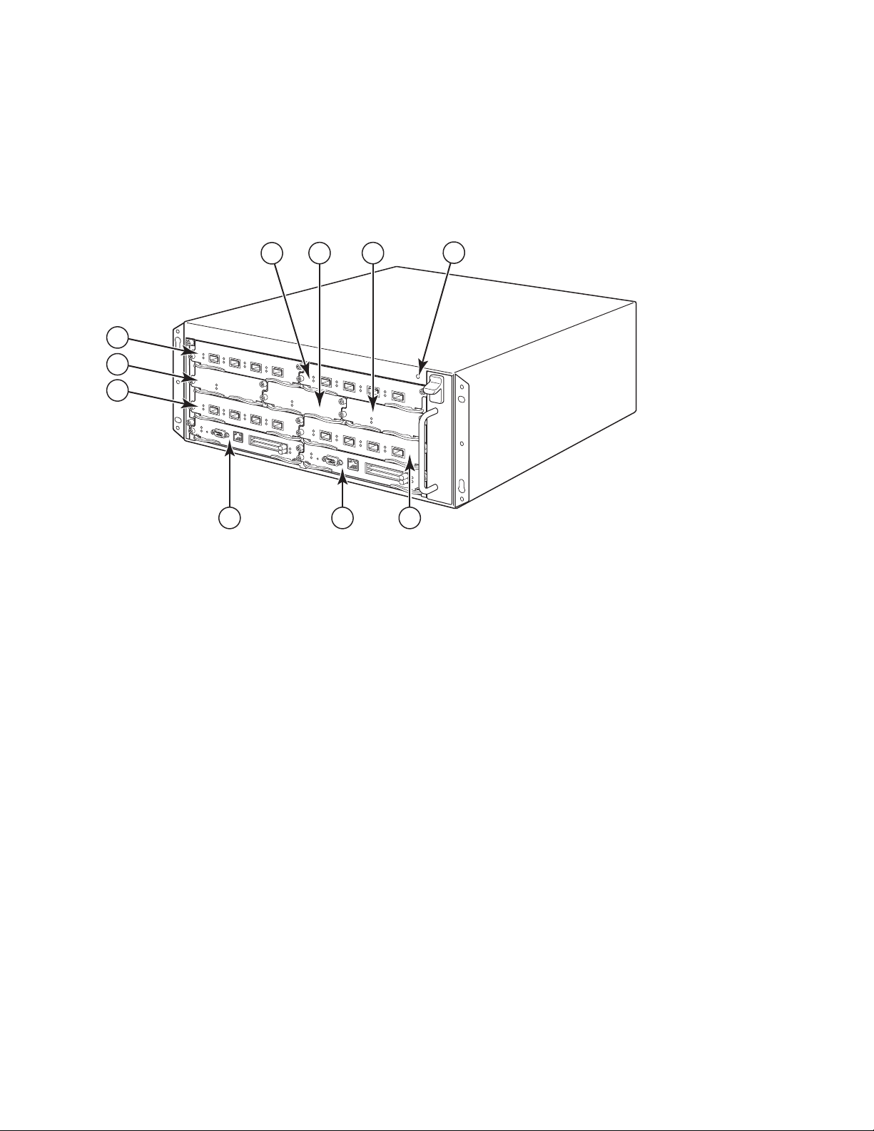
Figure 1 illustrates the PowerConnect B-MLXe Series 4-slot chassis and components location.
FIGURE 1
1 Interface slot 2 4 ESD connector 7 Interface slot 3 10 Interface slot 4
2 Switch fabric slot 2 5 Interface slot 1 8 Management slot 1
3 Switch fabric slot 3 6 Switch fabric slot 1 9 Management slot 2
PowerConnect B-MLXe 4-slot chassis
4 PowerConnect B-MLXe Getting Started Guide
53-1001995-01
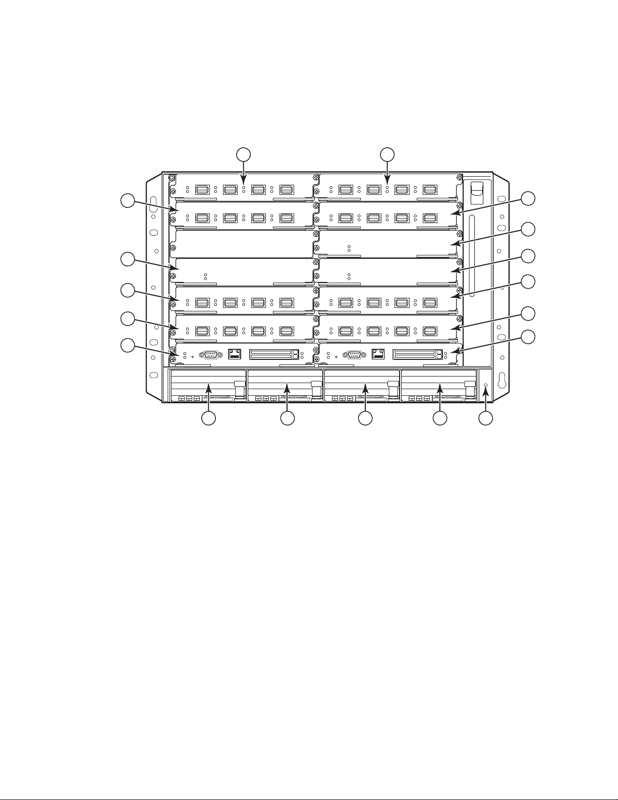
Figure 2 illustrates the PowerConnect B-MLXe Series 8-slot chassis and components location.
8
10
12
6
9
7
5
4
3
14 15
11
16 17
1 2
13
18
FIGURE 2
PowerConnect B-MLXe 8-slot chassis
1 Interface slot 1 6 Switch fabric slot 2 11 Interface slot 8 16 Power supply slot 3
2 interface slot 2 7 Switch fabric slot 3 12 Management slot 1 17 Power supply slot 4
3 Interface slot 3 8 Interface slot 5 13 Management slot 2 18 ESD connector
4 Interface slot 4 9 Interface slot 6 14 Power Supply slot 1
5 Switch Fabric slot 1 10 Interface slot 7 15 Power Supply slot 2
PowerConnect B-MLXe Getting Started Guide 5
53-1001995-01

Figure 3 illustrates the PowerConnect B-MLXe Series 16-slot chassis and components location.and components
12
13
14
15
16
17
18
19
20
21
22
23
1
2
3
4
5
6
7
8
91011
location.
FIGURE 3
PowerConnect B-MLXe 16-slot chassis
1-16 Interface slots 1-16 20 Switch fabric slot 4
17 Switch fabric slot 1 21 Management slot 1
18 Switch fabric slot 2 22 Management slot 2
19 Switch fabric slot 3 23 ESD connector
6 PowerConnect B-MLXe Getting Started Guide
53-1001995-01

Items required for installation
NOTE
This document describes how to set up the PowerConnect B-MLXe Series 4-slot, 8-slot, and 16-slot chassis and
mount them into 19-inch equipment racks using the brackets built onto each chassis. To center-mount the chassis
in a rack, order the mid-mount rack kit from your PowerConnect supplier. Installation instructions are provided with
the rack kit. This section describes items shipped with the PowerConnect B-MLXe Series and items you will need for
installation.
Items shipped with units
The following items are shipped:
•
The 4-slot chassis ships with the following components installed:
-
Two high-speed switch fabric modules.
-
A slot blank in each empty module slot. The slot blank covers a slot that does not currently have a module
installed in it, ensuring proper airflow.
-
A fan tray assembly, which is located in the front right side of the router. For more information about fans,
refer to your hardware installation guide.
-
One power supply (AC or DC).
•
The 8-slot chassis ships with the following components installed:
-
Two high-speed switch fabric modules.
-
A slot blank in each empty module slot. The slot blank covers a slot that does not currently have a module
installed in it, ensuring proper airflow.
-
A fan tray assembly, which is located in the front right side of the router. For more information about fans,
refer to your hardware installation guide.
-
Two power supplies (AC or DC).
•
The 16-slot chassis ships with the following components installed:
-
Three high-speed switch fabric modules.
-
A slot blank in each empty module slot. The slot blank covers a slot that does not currently have a module
installed in it, ensuring proper airflow.
-
A fan tray assembly, located in the front right side of the chassis, and two fan assemblies located at the rear
of the chassis. For more information about fans, refer to your hardware installation guide.
-
Four power supplies (AC or DC).
•
Warranty card.
•
A 115V AC power cable for each AC power supply that you purchase from Dell.
•
Web pointer card containing software images and user documentation (including this guide).
If any items are missing, contact the place of purchase.
Items that you must provide
•
Assembled 19-inch Electronic Industries Association cabinet (EIA310-D) equipment rack.
•
Standard #12-24 pan-head screws for mounting the chassis to equipment racks.
PowerConnect B-MLXe Getting Started Guide 7
53-1001995-01
•
NOTE
DANGER
DANGER
#2 Phillips-head screwdriver.
•
A large flat-blade screwdriver.
•
Mid-mount rack kit (optional). Order from your PowerConnect supplier.
•
An ESD wrist strap with a plug for connection to the ESD connector on the chassis.
Site planning and safety guidelines
The following steps and safety precautions are required to ensure correct installation and operation.
Site planning
Follow these steps to ensure your site is ready for installation.
Cabling infrastructure
Ensure that the proper cabling is installed in the site. For information on cabling, see your hardware installation
guide.
Installation location
Before installing the chassis, plan its location and orientation relative to other devices and equipment. For cooling
purposes, allow a minimum of 15.24 cm (6 in.) of space between the sides, front, and the back of the chassis and
walls or other obstructions. If a chassis is installed within a perforated enclosure, the perforations must have
openings of at least 60 percent of the surface.
The PowerConnect B-MLXe series chassis is suitable for installation in a Network Telecommunication facility and
where NEC requirements apply. Additionally it may be installed in either a Common Bonding Network (CBN) or Isolated
Bonding Network (IBN). It is not intended for Outside Plant installations (OSP).
Safety guidelines
Before proceeding with installation, read the cautions and warnings that apply to the PowerConnect B-MLXe Series.
General precautions
The procedures in this manual are for qualified service personnel.
All fiber-optic interfaces use Class 1 Lasers.
8 PowerConnect B-MLXe Getting Started Guide
53-1001995-01
CAUTION
Do not install the chassis in an environment where the operating ambient temperature might
CAUTION
CAUTION
CAUTION
CAUTION
DANGER
DANGER
DANGER
exceed 40οC (104οF).
Make sure the air flow around the front, sides, and back of the chassis is not restricted.
If you do not install a module in a slot, you must keep the slot blank in place. If you operate
the chassis with an uncovered slot, the system may overheat.
Never leave tools inside the chassis.
Power precautions
Use a separate branch circuit for each AC power cord for redundancy in case one of the
circuits fails.
Make sure to choose the appropriate circuit device, depending on the number of AC power
supplies installed in the chassis.
Disconnect the power cord from all power sources to completely remove power from the
chassis.
Make sure that the power source circuits are properly grounded, then use the power cord
supplied with the chassis to connect it to the power source.
PowerConnect B-MLXe Getting Started Guide 9
53-1001995-01

DANGER
If the installation requires a different power cord than the one supplied with the chassis,
DANGER
DANGER
CAUTION
CAUTION
CAUTION
make sure you use a power cord displaying the mark of the safety agency that defines the
regulations for power cords in your country. The mark is your assurance that the power cord
can be used safely with the chassis.
Make sure the rack or cabinet housing the chassis is adequately secured to prevent it from
becoming unstable or falling over.
Mount the chassis in a rack or cabinet as low as possible. Place the heaviest chassis at the
bottom and progressively place lighter units above.
Ensure that the chassis does not overload the power circuits, wiring, and over-current
protection. To determine the possibility of overloading the supply circuits, add the ampere
(amp) ratings of all devices installed on the same circuit as the chassis. Compare this total
with the rating limit for the circuit. The maximum ampere ratings are usually printed on the
chassis near the input power connectors.
B-MLXe series products with DC power sources are intended for installation in restricted
access areas only. A restricted access area is where access can be gained only by service
personnel through the use of a special tool, lock and key, or other means of security, and is
controlled by the authority responsible for the location.
B-MLXe series products with AC power sources are intended for installation in restricted
access areas only. A restricted access area is a location where access can be gained only by
service personnel through the use of a special tool, lock and key, or other means of security.
10 PowerConnect B-MLXe Getting Started Guide
53-1001995-01
CAUTION
For the DC input circuit to the system of a 16-slot chassis (1800W supply), make sure there
CAUTION
is a UL-Listed 60 amp circuit breaker, minimum -48VDC, double pole, on the input lugs to the
power supply. The input wiring for connection to the product should be copper wire, 6 AWG,
marked VW-1, and rated minimum 90οC.
For the NEBS-compliant installation of 16-slot chassis with AC and DC systems, use a ground
wire of at least 6 American Wire Gauge (AWG). The ground wire should have an
agency-approved crimped connector (provided with the device) attached to one end, with the
other end attached to building ground. The connector must be crimped with the proper tool,
allowing it to be connected to both ground screws on the enclosure. Before crimping the
ground wire into the provided ground lug, ensure the bare copper wire has been cleaned and
antioxidant is applied to the bare wire.
Unpacking the PowerConnect B-MLXe Series
The PowerConnect B-MLXe Series ships with several items. Review the items listed under “Items shipped with units”
on page 7, and verify the contents. If any items are missing, contact the place of purchase.
Remove your B-MLXe chassis from the shipping carton. Save the shipping carton and packing materials in case you
need to move or ship the chassis at a later time.
Installing a PowerConnect B-MLXe Series chassis in a rack
This section describes the following tasks:
•
“Preparing to mount a chassis in a rack”
•
“Removing shipping screws from the 4-slot and 8-slot chassis”
•
“Lifting guidelines for the 8-slot and 16-slot chassis”
•
“Mounting a chassis in a rack”
Preparing to mount a chassis in a rack
Because of the weight of a fully loaded PowerConnect B-MLXe Series chassis, Dell recommends mounting a chassis
in a rack before installing modules and AC power supplies if necessary.
In a standard 19-inch (EIA310-D) rack, you can install
•
Up to ten PowerConnect B-MLXe Series 4-slot chassis.
•
Up to six PowerConnect B-MLXe Series 8-slot chassis.
•
Up to three PowerConnect B-MLXe Series 16-slot chassis.
PowerConnect B-MLXe Getting Started Guide 11
53-1001995-01
For each PowerConnect B-MLXe Series chassis that you install in a rack, you must provide four standard #12-24
NOTE
DANGER
3
1
2
pan-head screws with which to mount and secure the chassis. Before performing this task, you should have an
assembled rack and a #2 Phillips-head screwdriver.
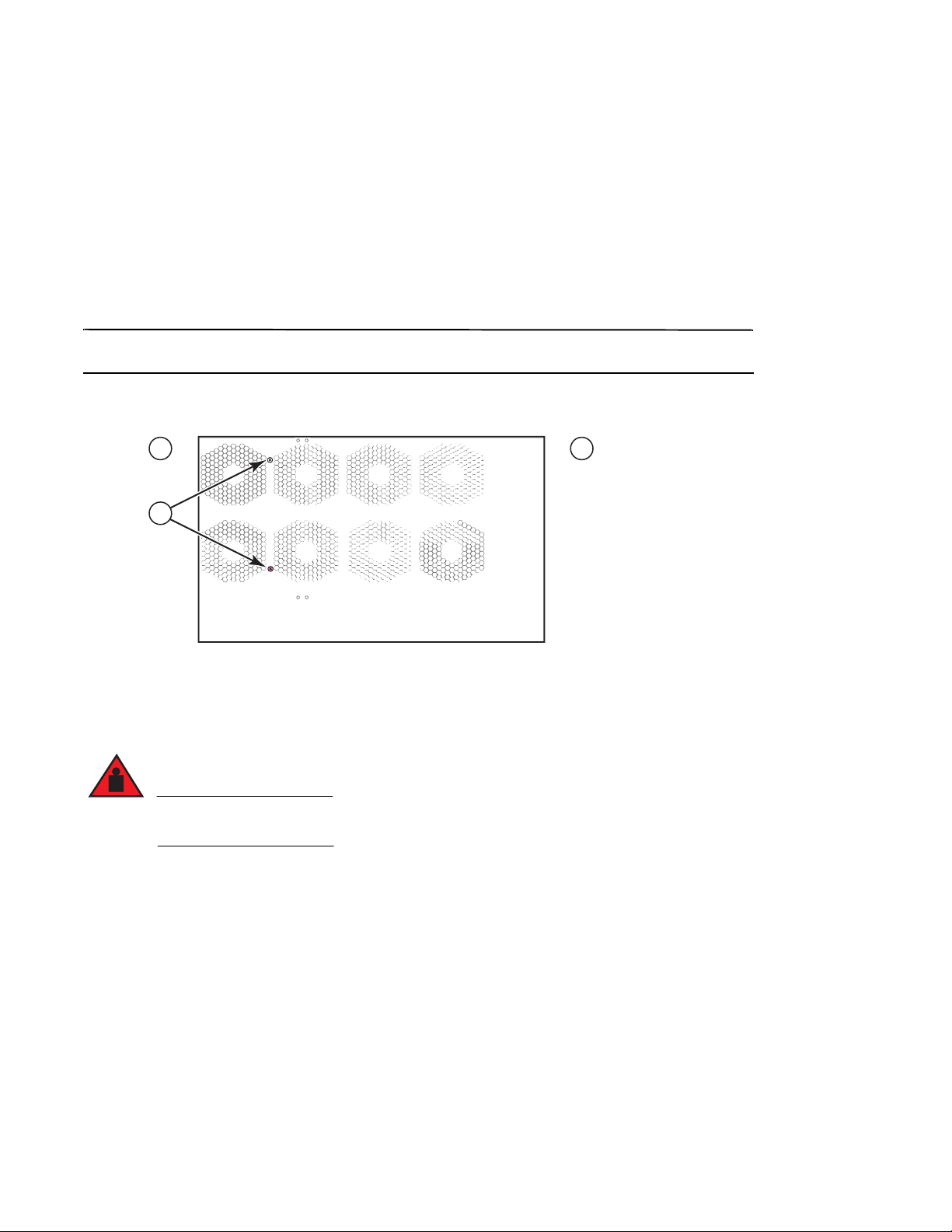
Removing shipping screws from the 4-slot and 8-slot chassis
The PowerConnect B-MLXe Series 4-slot and 8-slot units ship with two screws installed in the right side of the
chassis. These screws secure the fan tray and protect it from damage during shipment. You must remove these
screws before installing the router. Figure 4 on page 12 shows the location of these screws.
You will need a #2 Phillips screwdriver to remove these screws.
FIGURE 4
1 Front 2 Rear 3 Shipping screws
Removing the shipping screws from 4-slot and 8-slot chassis
Lifting guidelines for the 8-slot and 16-slot chassis
A fully-populated B-MLXe 16-slot chassis is heavy. TWO PEOPLE ARE REQUIRED WHEN LIFTING,
HANDLING, OR MOUNTING THESE DEVICES.
Follow these guidelines for lifting and moving the 8-slot or 16-slot chassis:
•
Before lifting or moving the chassis, disconnect all external cables.
•
Do not attempt to lift a fully configured chassis by yourself. Use two people to lift the chassis.
•
It is recommended that you remove chassis components before installing the chassis in a rack.
12 PowerConnect B-MLXe Getting Started Guide
53-1001995-01
Mounting a chassis in a rack
NOTE
5"
3"
1 2
Follow these steps to mount a PowerConnect B-MLXe Series chassis in a rack.
You must provide standard #12-24 pan-head screws to mount each chassis in a rack. You will need a Phillips
screwdriver to perform this task.
1. Determine the position of each chassis in the rack. For example, place units with the fewest modules near the
top of the rack, units with more modules near the middle of the rack, and fully populated units near the bottom
of the rack.
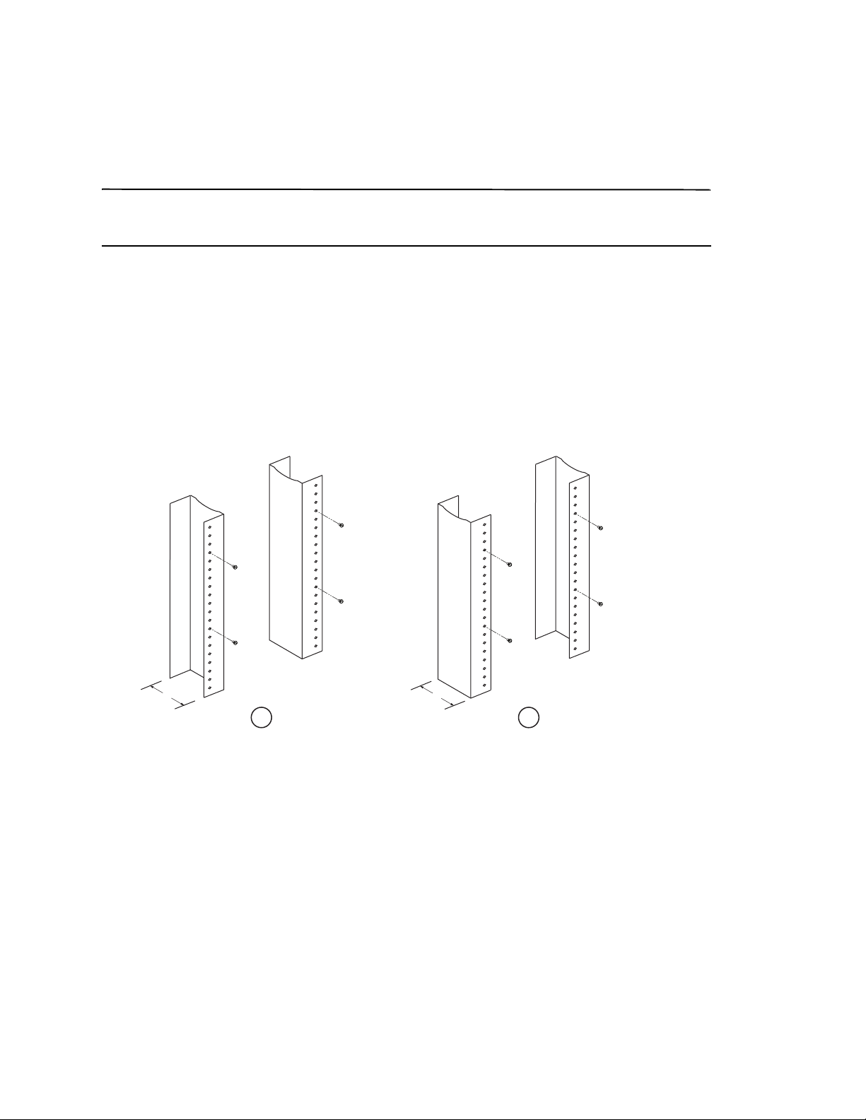
2. Using the keyhole slots in the chassis mounting brackets as a guide, align one screw per rack post, as shown in
Figure 5 on page 13. On one side of the rack, the screw should align with the top hole in the mounting bracket.
On the other side of the rack, the screw should align with the bottom hole of the mounting bracket. When
tightening these screws, leave approximately 1/4-inch of clearance between the back of the screw head and the
rack post.
FIGURE 5
1 Unequal flange equipment rack 2 Network equipment rack
Positioning the mounting screws in the rack posts
3. Starting with the chassis that will be in the lowest position in the rack, mount the chassis in the rack as shown in
the example of the 8-slot chassis in Figure 6. With two or more people lifting the chassis, slip the wide portion of
each keyhole slot over the corresponding mounting screw in the rack post.
PowerConnect B-MLXe Getting Started Guide 13
53-1001995-01
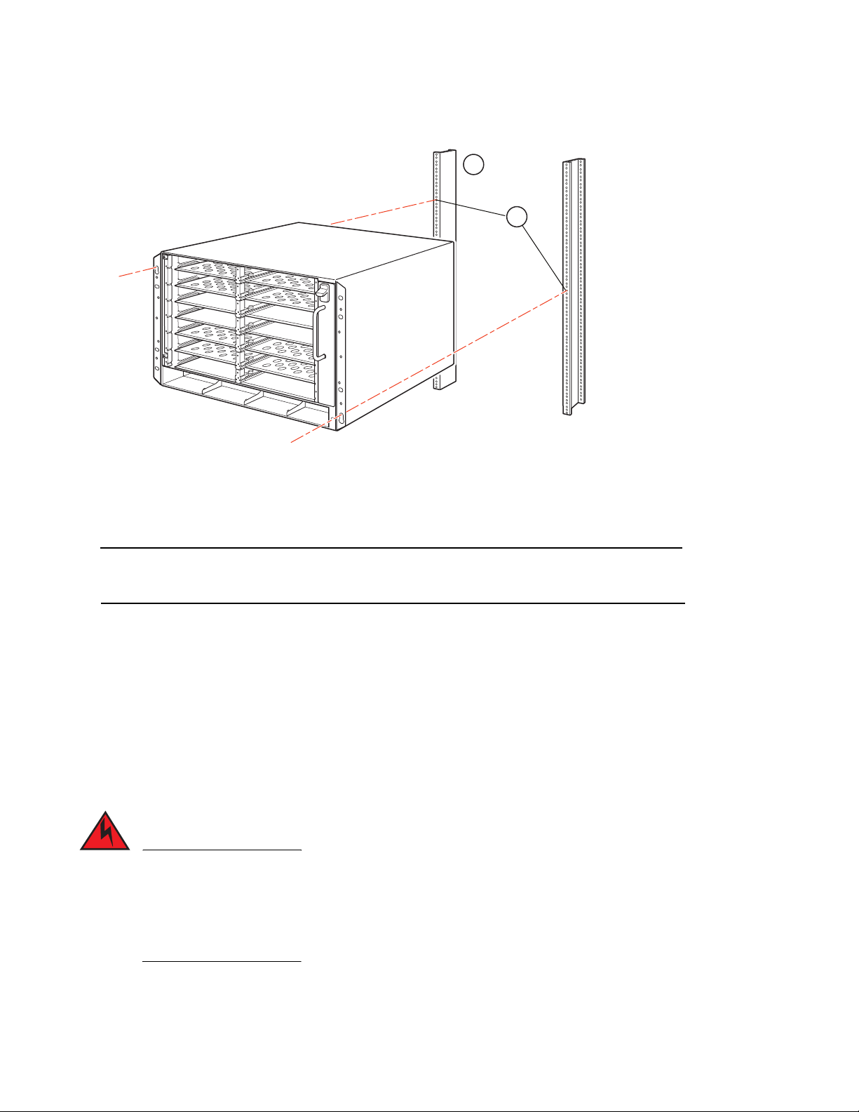
FIGURE 6
NOTE
DANGER
1
2
1 Equipment rack 2 Mounting holes
4. Slide the chassis down so that the mounting screw heads are in the narrow portion of the keyhole slots.
5. Tighten the screws to secure the chassis in place. For extra support, use additional screws.
Mounting the B-MLXe 8-slot chassis in a rack
For better grounding of the chassis to the rack, attach the chassis using star washers. You should also use star
washers with any single-hole grounding lugs to keep the lugs from rotating.
6. Repeat step 2 through step 5 to mount each chassis in the rack.
Installing modules
Use these procedures to install modules into empty slots. The same procedure applies to all modules.
The following sequence for installing multiple modules is important to ensure proper fit:
•
For the 4-slot and 8-slot chassis, install modules right-to-left, beginning with the lowest row and moving up.
•
For the 16-slot chassis, begin by filling the slots from the left side of the router, and work towards the right side.
The intra-building ports of the equipment or subassembly is suitable for connection to intra-building or
unexposed wiring or cabling only. The intra-building ports of the equipment or subassembly MUST NOT
be metallically connected to interfaces that connect to the outside plant (OSP) or its wiring. These
interfaces are designed for use as intra-building interfaces only (Type 2 or Type 4 ports as described in
GR-1089-CORE, Issue 4) and require isolation from the exposed OSP cabling. The addition of Primary
Protectors is not sufficient protection in order to connect these interfaces metallically to OSP wiring.
14 PowerConnect B-MLXe Getting Started Guide
53-1001995-01
NOTE
The PowerConnect B-MLXe Series modules are dedicated, which means that you must install them in the
CAUTION
CAUTION
CAUTION
PowerConnect B-MLXe Series chassis only. For example, if you attempt to install the PowerConnect B-MLXe Series
management module in another Dell chassis or a management module intended for another Dell chassis in the
PowerConnect B-MLXe Series chassis, the chassis and module will not function properly.
Tab le 1 provides the chassis slot numbers into which you must install the modules. Markings for the chassis slots
appear at the base of the slots.
Each PowerConnect B-MLXe Series chassis ships with the required switch fabric modules installed.
TAB LE 1
PowerConnect B-MLXe Series module Chassis slot number
Management modules for 4-slot and 8-slot chassis
Management modules for 16-slot chassis
Interface modules for 4-slot chassis
Interface modules for 8-slot chassis
Interface modules for 16-slot chassis
Switch fabric modules for 4-slot and 8-slot chassis
Switch fabric modules for 16-slot chassis
PowerConnect B-MLXe module installation
Active module – M1 (left)
Redundant module – M2 (right)
Active module – M1 (upper)
Redundant module – M2 (lower)
1 – 4
1 – 8
1 – 16
SF1 – SF3
SF1 – SF4
Use of a power screwdriver may twist the heads from the screws and is not recommended.
If you do not install a module in a slot, you must keep the slot blank in place. If you operate
the chassis with an uncovered slot, the system may overheat. Tighten the screws that secure
the slot blanks so that they remain in place when removing adjacent panels or modules.
If you are hot-swapping a module, allow a minimum of two seconds after a module (or power
supply or fan tray) has been removed before inserting a module in the same slot.
If you are installing a redundant management module, refer to the appropriate configuration guide for your product
for information about how the redundant module works, optional software configurations that you can perform, and
how to manage the redundancy feature.
PowerConnect B-MLXe Getting Started Guide 15
53-1001995-01

Before installing a module in the PowerConnect B-MLXe Series chassis, have the following on hand:
DANGER
NOTE
•
An ESD wrist strap with a plug for connection to the ESD connector on the PowerConnect B-MLXe Series chassis.
For safety reasons, the ESD wrist strap should contain a 1 megohm series resistor.
•
A large flat-head screwdriver.
Follow the steps given below to install a module in the PowerConnect B-MLXe Series chassis:
1. If you are installing a module in an empty slot that was not previously configured for a different module, go on to
step 2. If you are installing a module in a slot which may have been previously configured for a different module
type, remove the old configuration information using this procedure.
a. Use the show running-config command in config mode to determine the current configuration of the slot.
PowerConnect(config)# show running-config
Current configuration:
!
ver V5.0.0T163
module 1 ni-mlx-24-port-1g-copper
!
This example shows that slot 1 is currently configured for a 20-port 1 Gbps copper interface module.
b. With the module designation from show running-config command output, use the no module
<slot-number> <module-type> command to remove the configuration from slot 1.
PowerConnect(config)# no module 1 ni-mlx-20-port-1g-copper
This command removes the configuration from slot 1, leaving it ready for a new module.
2. Put on the ESD wrist strap and ground yourself by inserting the plug into the ESD connector on the chassis.
3. Remove the module from the packaging.
4. Insert the module into the slot, and slide the module along the card guide until the ejectors on either side of the
module rotate towards the module front panel.
When inserting a module in the chassis, make sure that the module faceplate does not overlap the faceplate of
an adjacent module.
5. Rotate the ejectors flush with the module faceplate. This action will fully seat the module in the backplane.
6. Tighten the two screws on the module faceplate by pushing them in and turning them clockwise. Complete the
tightening process using the flat-blade screwdriver.
7. E nt e r t he write memory command to ensure that the slot will be correctly configured for the new module after a
reboot.
PowerConnect(config)# write memory
Write startup-config done.
16 PowerConnect B-MLXe Getting Started Guide
53-1001995-01
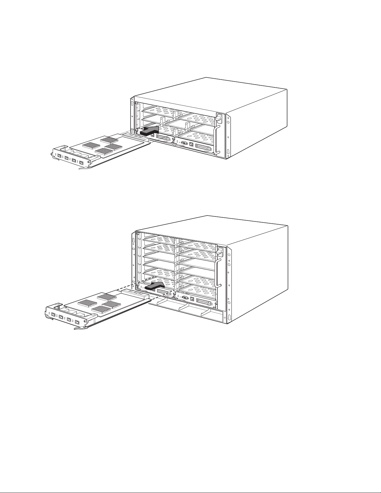
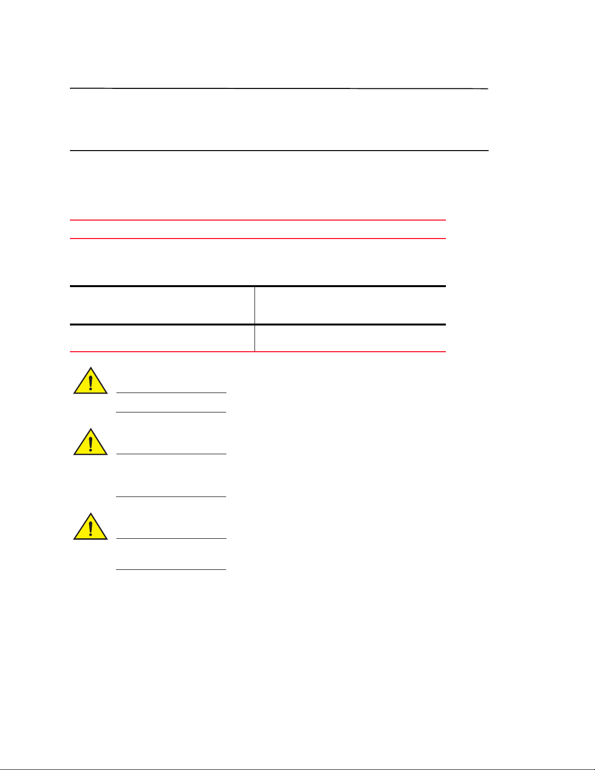
FIGURE 7
s
Installing a module in 4-slot chassis
FIGURE 8
Installing a module in an 8-slot chassis
PowerConnect B-MLXe Getting Started Guide 17
53-1001995-01
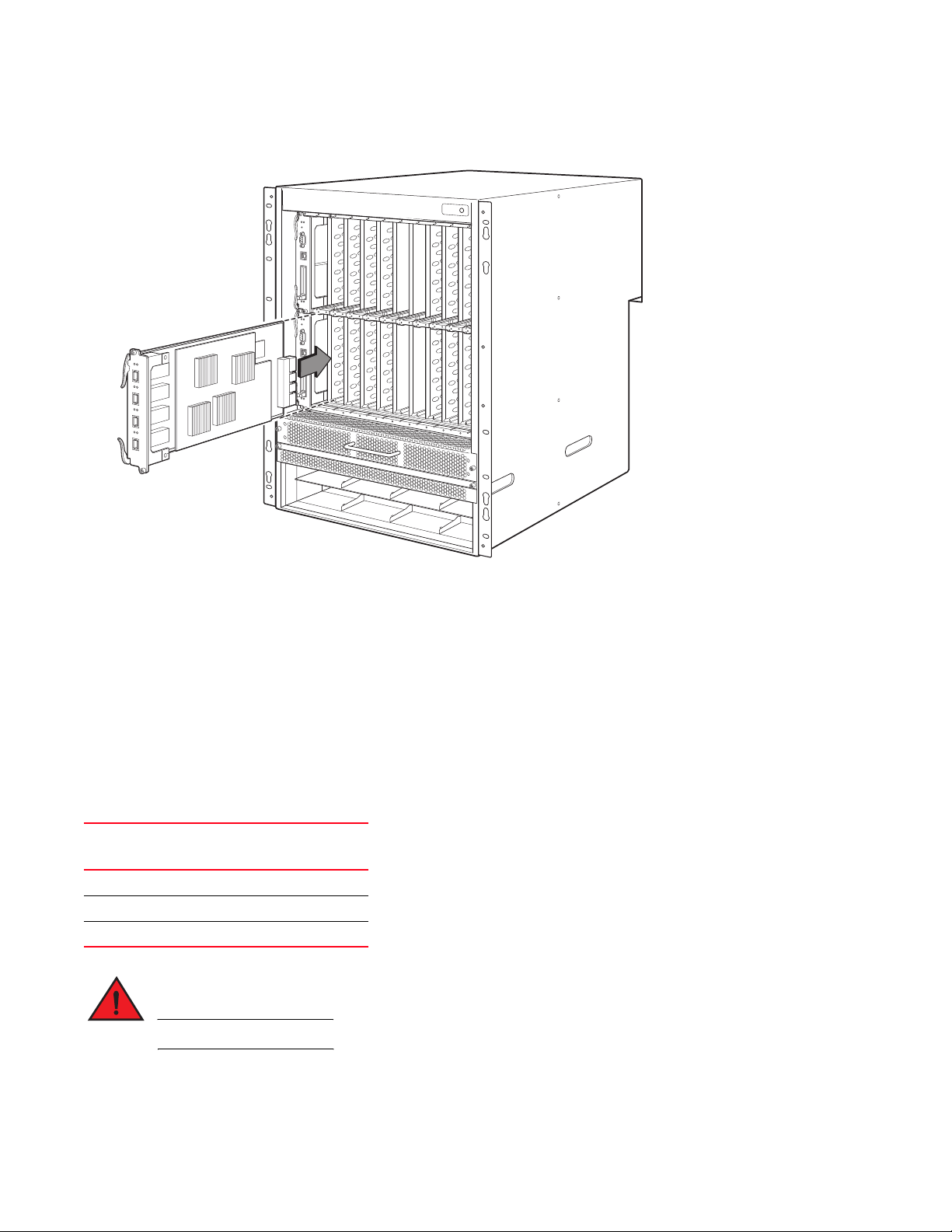
FIGURE 9
DANGER
Installing a module in a B-MLXe-16 chassis
Power supply, switch fabric, and fan requirements
For details on power supply, switch fabric, and fan requirements for modules installed in PowerConnect B-MLXe
Series units, refer to your hardware installation guide.
Installing power supplies
Tabl e 2 lists the number of power supplies (AC or DC) installed in the PowerConnect B-MLXe Series at the factory and
the maximum that you can install in each unit to add redundancy.
TABLE 2
Chassis Type Installed Power
4-slot 1 3
8-slot 2 4
16-slot 4 8
Power supplies for B-MLXe Series
Maximum
Supplies
High Touch Current. Earth connection is essential before connecting supply.
Power Supplies
Power supply installation steps
Follow these steps to install a power supply. You need a small Phillips or flat-head screwdriver to perform this task.
18 PowerConnect B-MLXe Getting Started Guide
53-1001995-01
1. Remove the power supply slot blank.
CAUTION
CAUTION
Empty power supply slots must be covered with slot blanks.
2. Remove the power supply from the packaging.
3. Insert the power supply into the slot, using the guides on each side of the slot. Refer to Figure .
Carefully follow the mechanical guides on each side of the power supply slot and make sure the power
supply is properly inserted in the guides. Never insert the power supply upside down.
4. For the 4-slot chassis, follow these steps, then continue with step 6.
a. Push the power supply front panel into the router until it engages the backplane connector.
b. Rotate the ejector levers towards the front of the power supply to secure it in place.
c. Tighten the two screws on the power supply front panel by pushing them in and turning them clockwise.
Finish tightening the screws using the flat-blade screwdriver.
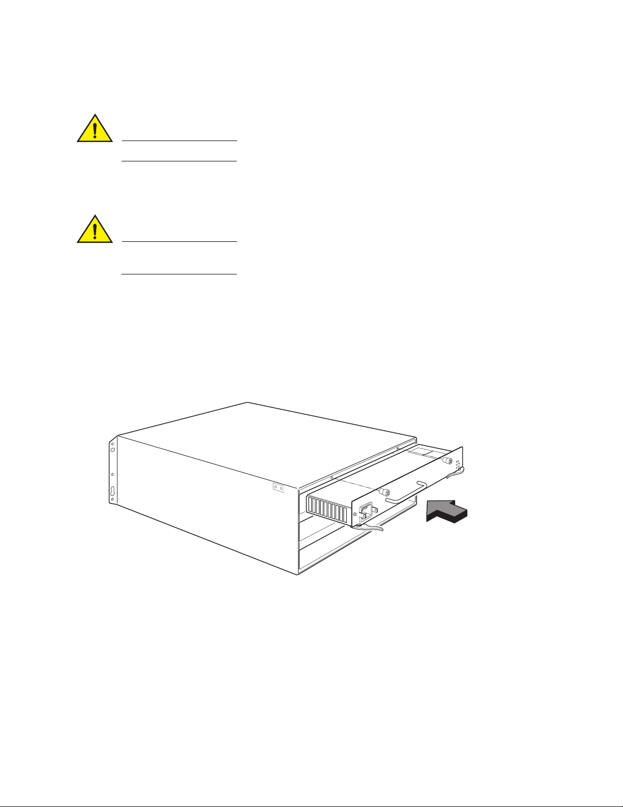
FIGURE 10
Installing a power supply in a 4-slot chassis
5. For the 8-slot and 16-slot chassis, follow these steps, then continue with step 6.
d. Slide the card along the card guide until fully inserted, then push the power supply front panel toward the
back of the chassis. This action causes the power supply connector to latch into the backplane connector.
e. Gently pull the handle on the power supply front panel upward and toward the top of the power supply front
panel. This action locks the power supply in place.
PowerConnect B-MLXe Getting Started Guide 19
53-1001995-01
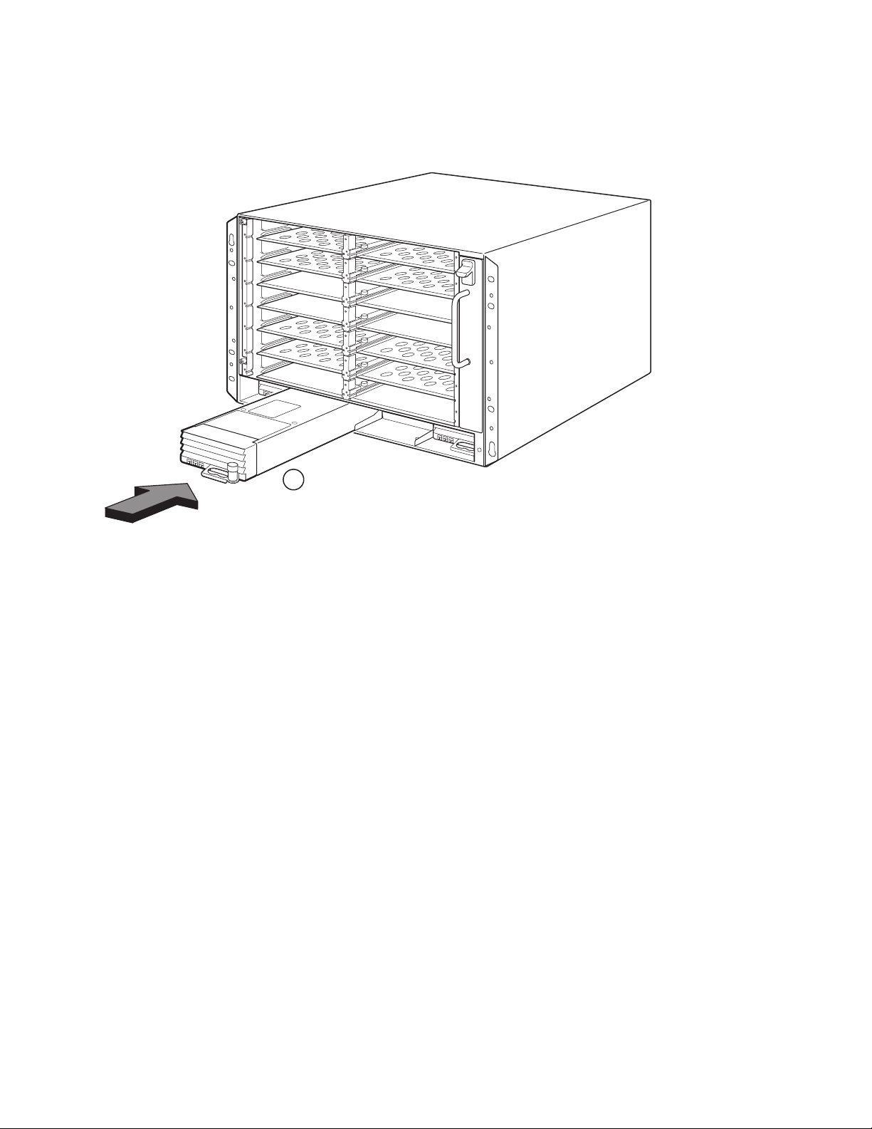
FIGURE 11
1
1 Power supply
Installing a power supply in an 8-slot chassis
20 PowerConnect B-MLXe Getting Started Guide
53-1001995-01

FIGURE 12
1
2
Installing a power supply in a 16-slot chassis
1 Power supply 2 Release latch
6. For information about connecting power to the router, refer to “Connecting AC power” on page 21 or “Connecting
DC Power” on page 22.
7. For information about powering on the system, refer to “Activating the power source” on page 25.
Connecting AC power
AC power connection steps
1. Locate the power receptacles on the power supplies in the back panel of the B-MLXe chassis.
2. Lift the cord retainer and connect an AC power cord to the receptacle.
3. Snap the cord retainer over the power plug to hold it in place.
PowerConnect B-MLXe Getting Started Guide 21
53-1001995-01
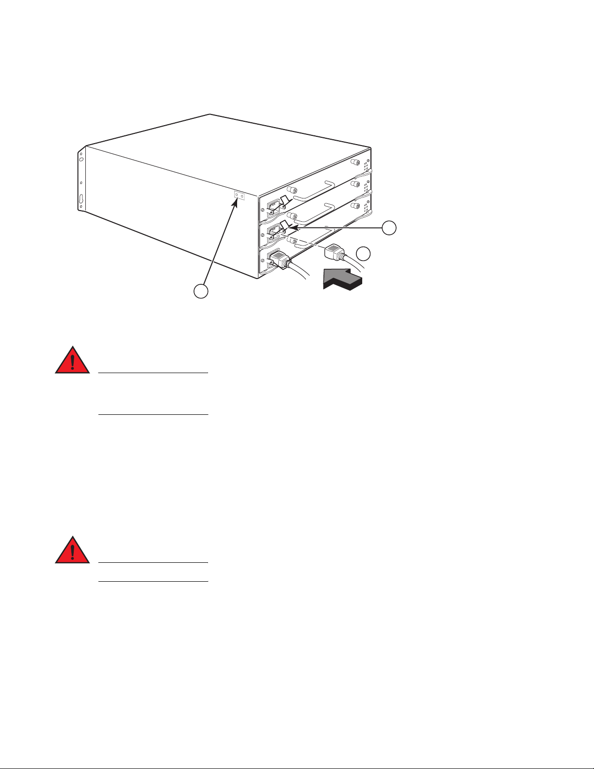
FIGURE 13
DANGER
DANGER
1
2
3
1 Ground point 2 Power Cord 3 Cord retainer
Example of connecting a power cord to an AC power supply installed in B-MLXe 4-slot chassis
If the installation requires a different power cord than the one supplied with the chassis, make sure you
use a power cord displaying the mark of the safety agency that defines the regulations for power cords in
your country. The mark is your assurance that the power cord can be used safely with the chassis.
4. For information about powering on the system, see “Activating the power source” on page 25.
Connecting DC Power
You can use a DC power source for the PowerConnect B-MLXe Series chassis. This is supported through use of a
DC-to-DC power supply. DC power must be supplied at 48 V and 30 A. The DC-to-DC supply provides the DC power to
the chassis at 12 V and 100 A.
The procedure in this section is for qualified service personnel.
Follow the steps given below to connect a DC power source.
1. Use a flat-blade screwdriver to remove the two screws holding the plastic cover over the power supply lugs.
22 PowerConnect B-MLXe Getting Started Guide
53-1001995-01
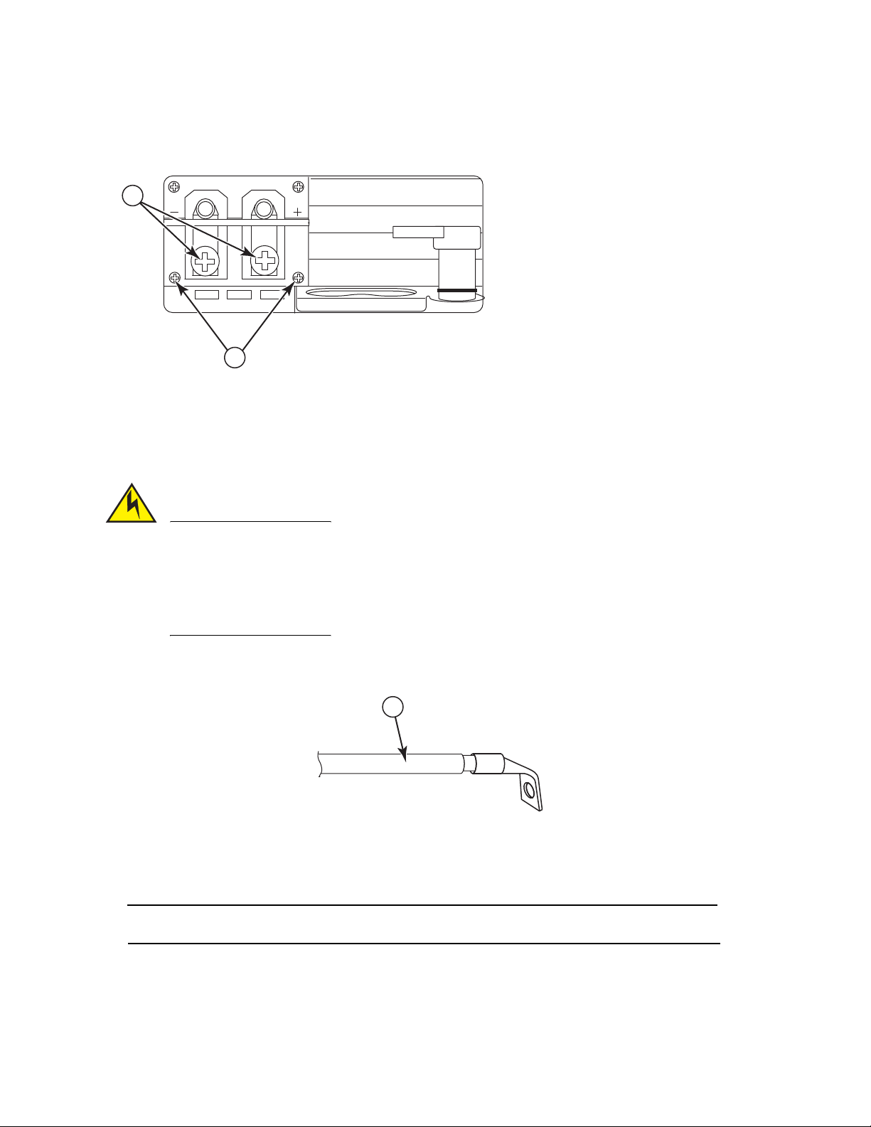
FIGURE 14
CAUTION
NOTE
1
DC power supply for the 8-slot and 16-slot chassis
2
DC IN
DC OUT
ALM
1
1 Screws holding plastic cover 2 Screws holding power lugs
2. Use a Phillips head screwdriver to remove each of the power lugs.
3. Crimp #8 AWG power supply wire into the power lugs and reconnect the power lugs to the power supply unit.
Refer to Figure 15.
For the NEBS compliant installation of a PowerConnect B-MLXe Series with AC and DC system use a
ground wire of at least 6 American Wire Gauge (AWG). The ground wire should have an agency-approved
crimped connector (provided with the chassis) attached to one end, with the other end attached to
building ground. The connector must be crimped with the proper tool, allowing it to be connected to both
ground screws on the enclosure. Before crimping the ground wire into the provided ground lug, ensure
the bare copper wire has been cleaned and antioxidant is applied to the bare wire.
FIGURE 15
1 #8 AWG power supply wire
Crimping the power supply wire in the lug
4. Re-attach the cover over the power supply lugs that was removed in step 1.
5. Connect the -48V cable to the negative terminal and the 0V cable to the positive terminal on the power supply.
DC return must be isolated from the router ground (DC-I) when connecting to the power supply.
This equipment installation must meet NEC/CEC code requirements. Consult local authorities for regulations.
PowerConnect B-MLXe Getting Started Guide 23
53-1001995-01

Managing cables
NOTE
For information on managing cables attached to the PowerConnect B-MLXe Series, refer to your hardware
installation guide.
Attaching a management station
You can manage the PowerConnect B-MLXe Series system in the following ways:
•
You can connect a PC or terminal to the management module’s serial (Console) port for a direct connection.
From this interface, you can configure the 10BaseT/100BaseTX/1000BaseTX Ethernet (management) port with
an IP address and either Telnet or SSH. This enables you to manage the device through the
10BaseT/100BaseTX/1000BaseTX Ethernet (management) port using either Telnet or SSH.
•
You can connect the PowerConnect B-MLXe Series chassis to your existing management network and manage
the chassis, along with other network devices, from a management station. To do this, you can connect a
chassis to the management module’s 10BaseT/100BaseTX/1000BaseTX Ethernet (management) port.
The existing management network into which you can connect the 10/100 Ethernet port must be separate and
isolated from the network over which user packets are switched and routed.
For information about connecting a PC or terminal to the management module’s Console port or management port,
see “Attaching a PC or terminal to the Console port or Ethernet port,” next. For information about connecting a
management port to a network, see “Attaching the management module’s Ethernet Port to a network” on page 25.
Attaching a PC or terminal to the Console port or Ethernet port
The management module’s Console port (which has a male DB-9 serial connector), and 10BaseT/100Base TX
Ethernet port (which has an RJ-45 UTP connector) allow you to attach a PC or terminal. From the Console port, you
can access the PowerConnect B-MLXe Series chassis CLI directly from the PC or terminal or via a Telnet connection
to the PC or terminal. From the Ethernet port, you can access the PowerConnect B-MLXe Series CLI or Web
management interface directly from the PC or terminal or via a Telnet connection to the PC or terminal.
Before performing this task, you need the following items:
•
PC running a terminal emulation application or a terminal.
•
If connecting the PC or terminal to the Console port, a straight-through EIA/TIA DB-9 serial cable with one end
terminated in a female DB-9 connector and the other end terminated in a male or female DB-9 or DB-25
connector, depending on the specifications of your PC or terminal. You can order the serial cable separately from
Dell or build your own cable. If you prefer to build your own, see the pinout information in your hardware
installation guide.
•
If connecting the PC or terminal to the Ethernet port, a Category 5 UTP crossover cable, which you must supply.
For information about the management port pin assignments, refer to your hardware installation guide.
Follow the steps given below to attach a PC or terminal to the Console port or Ethernet port.
1. Connect a PC or terminal to the Console port or Ethernet port using the appropriate cable.
24 PowerConnect B-MLXe Getting Started Guide
53-1001995-01
2. Open the terminal emulation program, and set the session parameters as follows:
CAUTION
DANGER
NOTE
NOTE
•
Baud: 9600 bps
•
Data bits: 8
•
Parity: None
•
Stop bits: 1
•
Flow control: None
Attaching the management module’s Ethernet Port to a network
The management module’s 10BaseT/100BaseTX/1000BaseTX Ethernet (management) port (RJ-45 UTP connector)
allows you to connect the management port to a network. A management station in your existing management
network can then access a PowerConnect B-MLXe Series chassis using the management application.
To attach the management module’s Ethernet port to a network, you need a Category 5 UTP straight-through cable
(not supplied by Dell). Connect one end of the straight-through cable to the management port and the other end to
the network.
Activating the power source
After you complete the hardware installation, you can power-on your power source.
1. Verify that all modules and power supplies are fully and properly installed and no module slots are uncovered.
If you do not install a module in a slot, you must keep the slot blank in place. If you run the chassis with
an uncovered slot, the system may overheat.
2. If your power source is AC, attach one end of a Dell-supplied AC power cord to the AC power supply as described
in “Connecting AC power” on page 21.
Insert the other end into a 115V or 120V wall outlet. Repeat this step for each installed AC power supply.
If the installation requires a different power cord than the one supplied with the device, make sure you
use a power cord displaying the mark of the safety agency that defines the regulations for power cords in
your country. The mark is your assurance that the power cord can be used safely with the device.
The PowerConnect B-MLXe Series chassis is designed to provide uninterrupted service even when you insert or
remove the management modules and the interface modules. Therefore, the system does not have a separate
on/off power switch. To turn the system off, simply unplug the power cords.
The wall outlet should be installed near the equipment and should be easily accessible.
PowerConnect B-MLXe Getting Started Guide 25
53-1001995-01

3. If you are supplying a DC power source to a PowerConnect B-MLXe Series chassis, attach the power cables to
PowerConnect# show module
Module Status Ports Starting MAC
M1 (upper): NI-MLX-MR Mgmt Module Active
M2 (lower):
F0: NI-MLX-MR Switch Fabric Module Active
S1:
S2:
S3:
S4: NetIron 4-Port 10Gig Module CARD_STATE_UP 4 000c.db80.0000
S5: NetIron 4-Port 10Gig Module CARD_STATE_UP 4 000c.db80.0000
S6: NetIron 4-Port 10Gig Module CARD_STATE_UP 4 000c.db80.0000
S7:
the DC power supply as described in “Connecting DC Power” on page 22.
Connect the other end of the cables to the DC power source. Repeat this step for each installed DC power
supply. Then switch on the power source.
4. Verify that the PowerConnect B-MLXe Series chassis has initialized successfully. For information, see “Verifying
proper operation,” below.
Verifying proper operation
To verify the proper operation of the PowerConnect B-MLXe Series chassis after power on, you can do the following:
•
Observe the LEDs.
•
Display the status of the modules using the CLI.
Observing the LEDs
After a PowerConnect B-MLXe Series chassis powers on, you can observe its LEDs to verify that it initialized
successfully. Refer to your hardware installation guide for a complete description of LED operation and status
messages displayed through the CLI show module command.
If a problem persists, contact technical support.
Displaying the module status
After you have attached a PC or terminal to the management module’s Console or Ethernet port and the
PowerConnect B-MLXe Series chassis has initialized successfully, press Enter to display the following CLI prompt in
the terminal emulation window:
PowerConnect>
If you do not see this prompt, do the following:
1. Make sure the cable is securely connected to your PC or terminal and the Console port or Ethernet port.
2. Check the settings in your terminal emulation program. In addition to the session settings listed in “Attaching a
PC or terminal to the Console port or Ethernet port” on page 24, make sure the terminal emulation session is
running on the same serial port you attached to the Console port.
If you see this prompt (PowerConnect>), you are now connected to the system and can display the status of the
modules using the CLI. Enter the following command at any CLI level:
26 PowerConnect B-MLXe Getting Started Guide
53-1001995-01

Assigning passwords
NOTE
NOTE
NOTE
By default, the PowerConnect B-MLXe Series CLI is not protected by passwords. To secure CLI access, Dell strongly
recommends assigning passwords.
The CLI contains the following access levels:
•
Privileged EXEC – This level is also called the Enable level and can be secured by a password. From this level you
can manage files on the management module flash memory or a PCMCIA flash card in the management module
slots 1 or 2, save the system configuration to flash memory, and clear caches.
•
CONFIG – The configuration level. This level lets you configure the system’s IP address and configure routing
features. To access the CONFIG mode, you must already be logged into the Privileged level of the EXEC mode.
You can set the following levels of Enable passwords:
•
Super User – Allows complete read-and-write access to the system. This is generally for system administrators
and is the only password level that allows you to configure passwords.
You must set a super user password before you can set other types of passwords.
•
Port Configuration – Allows read-and-write access for specific ports but not for global (system-wide) parameters.
•
Read Only – Allows access to the Privileged EXEC mode and CONFIG mode but only with read access.
To set passwords:
1. At the opening CLI prompt, enter the following command to change to the Privileged level of the EXEC mode:
PowerConnect> enable
PowerConnect#
2. Access the CONFIG level of the CLI by entering the following command:
PowerConnect# configure terminal
PowerConnect(config)#
3. Enter the following command to set the super-user password:
PowerConnect(config)# enable super-user-password <text>
You must set the super-user password before you can set other types of passwords.
4. Enter the following commands to set the port configuration and read-only passwords:
PowerConnect(config)# enable port-config-password <text>
PowerConnect(config)# enable read-only-password <text>
If you forget your super-user password, see the Release Notes.
The read-only--password and the port-config password should be difference from the super-user password.
Passwords can be up to 48 characters long.
PowerConnect B-MLXe Getting Started Guide 27
53-1001995-01

Configuring IP addresses
The PowerConnect B-MLXe Series implement separate data and control planes. This architecture affects how you
assign IP addresses. Tabl e 3 outlines the interfaces to which you can assign IP addresses.
In this table, “in band” refers to an interface over which user packets are routed, while “out of band” refers to an
interface over which control packets related to system management are forwarded.
TABLE 3
Interface Associated physical port Out of band or in band
Assigning IP addresses
Management interface Ethernet 10/100/1000 port on active
or redundant management module
Any interface over which user packets are routed Any interface module port In band
Any virtual interface over which user packets are routed Any interface port In band
Loopback interface – In band
This section describes the following:
•
PowerConnect B-MLXe Series support of sub-net masks
•
How to assign an IP address to a management interface
•
How to assign an IP address to an interface or virtual interface over which user packets are routed
Out of band
Support of subnet masks
The PowerConnect B-MLXe Series supports both classical IP network masks (Class A, B, and C subnet masks, and so
on) and Classless Interdomain Routing (CIDR) network prefix masks.
•
To enter a classical network mask, enter the mask in IP address format. For example, enter
“209.157.22.99 255.255.255.0” for an IP address with a Class-C subnet mask.
•
To enter a prefix number for a network mask, enter a forward slash (/) and the number of bits in the mask
immediately after the IP address. For example, enter “209.157.22.99/24” for an IP address that has a network
mask with 24 significant (“mask”) bits.
Assigning an IP address to a management interface
Instead of assigning a global IP address to the B-MLXe for system management purposes, you must assign an IP
address to the active management module. If the active management module becomes unavailable and the
redundant module becomes the active module, the IP address is automatically assigned to the new active
management module.
For example, to assign the IP address 10.0.1.1 to the management interface, do the following:
1. At the opening CLI prompt, enter enable:
PowerConnect> enable
2. Enter the following command at the Privileged EXEC level prompt (for example, PowerConnect#), then press
Enter. This command erases the factory test configuration if still present:
PowerConnect# erase startup-config
28 PowerConnect B-MLXe Getting Started Guide
53-1001995-01
Loading...