


 Loading...
Dell™ PowerConnect™ 27XX
Systems
User’s Guide
w w w . d e l l . c o m | s u p p o r t . d e l l . c o m

Notes, Notices, and Cautions
NOTE: A NOTE indicates important information that helps you make better use of your computer.
NOTICE: A NOTICE indicates either potential damage to hardware or loss of data and tells you how to avoid the problem.
 CAUTION: A CAUTION indicates a potential for property damage, personal injury, or death.
___________________
Information in this document is subject to change without notice. © 2006 Dell Inc. All rights reserved.
Reproduction in any manner whatsoever without the written permission of Dell Inc. is strictly forbidden.
Trademarks used in this text: Dell, Dell OpenManage, the DELL logo, and PowerConnect are trademarks of Dell Inc. Microsoft is a registered trademark of Microsoft Corporation.
Other trademarks and trade names may be used in this document to refer to either the entities claiming the marks and names or their products. Dell Inc. disclaims any proprietary interest in trademarks and trade names other than its own.
Models PC2708, PC2716, PC2724, PC2748
October 2006

Contents
1 |
Introduction |
|
|
System Description . . . . . . . . . . . . . . . . . . . . . . . . . . . . |
7 |
|
8 1-Gigabit Ethernet Ports . . . . . . . . . . . . . . . . . . . . . . . |
7 |
|
16 1-Gigabit Ethernet Ports . . . . . . . . . . . . . . . . . . . . . . |
8 |
|
24 1-Gigabit Ethernet Ports + 2 SFP Combo ports . . . . . . . . . . . . |
8 |
|
48 1-Gigabit Ethernet Ports . . . . . . . . . . . . . . . . . . . . . . |
8 |
|
Features. . . . . . . . . . . . . . . . . . . . . . . . . . . . . . . . . . |
9 |
|
General Features . . . . . . . . . . . . . . . . . . . . . . . . . . . |
9 |
|
MAC Address Supported Features . . . . . . . . . . . . . . . . . . . |
11 |
|
Layer 2 Features . . . . . . . . . . . . . . . . . . . . . . . . . . . |
11 |
|
VLAN Supported Features . . . . . . . . . . . . . . . . . . . . . . . |
12 |
|
Class of Service (CoS) Features . . . . . . . . . . . . . . . . . . . . |
12 |
|
Ethernet Switch Management Features . . . . . . . . . . . . . . . . |
13 |
|
Port Default Settings . . . . . . . . . . . . . . . . . . . . . . . . . |
13 |
2 Hardware Description
Switch Port Configurations. . . . . . . . . . . . . . . . . . . . . . . . . |
15 |
PowerConnect 2708/2716/2724/2748 Front Panel Port Description . . . . |
15 |
Physical Dimensions. . . . . . . . . . . . . . . . . . . . . . . . . . . . |
19 |
LED Definitions . . . . . . . . . . . . . . . . . . . . . . . . . . . . . . |
19 |
Power LED . . . . . . . . . . . . . . . . . . . . . . . . . . . . . . |
19 |
Managed Mode LED. . . . . . . . . . . . . . . . . . . . . . . . . . |
19 |
Fan LED (2748 only) . . . . . . . . . . . . . . . . . . . . . . . . . . |
20 |
Port LEDs . . . . . . . . . . . . . . . . . . . . . . . . . . . . . . . |
20 |
Managed Mode Button . . . . . . . . . . . . . . . . . . . . . . . . |
21 |
Switch Ventilation Fan. . . . . . . . . . . . . . . . . . . . . . . . . |
22 |
Cables, Port Connections, and Pinout Information . . . . . . . . . . . . . . |
22 |
1000BASE-T Cable Requirements . . . . . . . . . . . . . . . . . . . |
22 |
RJ-45 Connections for 10/100/1000BASE-T Ports . . . . . . . . . . . . |
22 |
SFP Ports . . . . . . . . . . . . . . . . . . . . . . . . . . . . . . . |
23 |
Pin Connections for SFP Interfaces . . . . . . . . . . . . . . . . . . |
24 |
Contents 3

Power Connectors . . . . . . . . . . . . . . . . . . . . . . . . . . . . . |
24 |
Internal Power Supply Connector . . . . . . . . . . . . . . . . . . . |
24 |
3 Installing the Dell™ PowerConnect™ 27XX
Installation Precautions . . . . . . . . . . . . . . . . . . . . . . . . . . |
25 |
Overview . . . . . . . . . . . . . . . . . . . . . . . . . . . . . . . . . |
25 |
Site Requirements . . . . . . . . . . . . . . . . . . . . . . . . . . . . . |
26 |
Unpacking. . . . . . . . . . . . . . . . . . . . . . . . . . . . . . . . . |
26 |
Safety . . . . . . . . . . . . . . . . . . . . . . . . . . . . . . . . |
26 |
Handling Static Sensitive Devices . . . . . . . . . . . . . . . . . . . |
27 |
Package Contents. . . . . . . . . . . . . . . . . . . . . . . . . . . |
27 |
Unpacking the Device . . . . . . . . . . . . . . . . . . . . . . . . . |
27 |
Mounting the Device. . . . . . . . . . . . . . . . . . . . . . . . . . . . |
28 |
Installation Precautions . . . . . . . . . . . . . . . . . . . . . . . . . . |
28 |
Installing the Device . . . . . . . . . . . . . . . . . . . . . . . . . . . . |
29 |
Installing the Device in a Rack . . . . . . . . . . . . . . . . . . . . . |
29 |
Installing the Device on a Flat Surface . . . . . . . . . . . . . . . . . |
30 |
Connecting the Device to AC Power Supply . . . . . . . . . . . . . . |
31 |
Connecting the Device to the Network . . . . . . . . . . . . . . . . . . . |
32 |
4 |
Starting and Configuring the Dell™ PowerConnect™ 27XX |
|
|
Viewing Switch Operation . . . . . . . . . . . . . . . . . . . . . . . . . |
33 |
|
Initial Configuration . . . . . . . . . . . . . . . . . . . . . . . . . . . . |
33 |
5 |
Using the Dell™ OpenManage™ Switch Administrator |
|
|
Understanding the Interface . . . . . . . . . . . . . . . . . . . . . . . . |
37 |
|
Using the OpenManage Switch Administrator Buttons . . . . . . . . . . . |
39 |
|
Information Buttons . . . . . . . . . . . . . . . . . . . . . . . . . . |
39 |
|
PowerConnect Switch Management Buttons . . . . . . . . . . . . . . |
39 |
|
Starting the Application . . . . . . . . . . . . . . . . . . . . . . . . . . |
40 |
4 Contents

|
Resetting the Device . . . . . . . . . . . . . . . . . . . . . . . . . . . . |
41 |
|
Displaying Configuration on Demand . . . . . . . . . . . . . . . . . . . . |
42 |
6 |
Configuring System Information |
|
|
Defining Switch Information . . . . . . . . . . . . . . . . . . . . . . . . |
43 |
|
Viewing the Switch Status . . . . . . . . . . . . . . . . . . . . . . . |
43 |
|
Viewing System IP Address . . . . . . . . . . . . . . . . . . . . . . |
44 |
|
Defining Interface Configuration . . . . . . . . . . . . . . . . . . . . |
47 |
|
Viewing Jumbo Frames . . . . . . . . . . . . . . . . . . . . . . . . |
49 |
|
Creating VLAN Membership . . . . . . . . . . . . . . . . . . . . . . |
50 |
|
Defining VLAN Interface Settings . . . . . . . . . . . . . . . . . . . |
51 |
|
Configuring LAG Membership . . . . . . . . . . . . . . . . . . . . . |
52 |
|
Managing System Files . . . . . . . . . . . . . . . . . . . . . . . . . . |
54 |
|
Downloading Files From Server . . . . . . . . . . . . . . . . . . . . |
55 |
|
Downloading Files From Server . . . . . . . . . . . . . . . . . . . . |
55 |
|
Local User Database . . . . . . . . . . . . . . . . . . . . . . . . . |
60 |
|
Integrated Cable Test for Copper Cables . . . . . . . . . . . . . . . . |
61 |
|
Optical Transceivers Diagnostics . . . . . . . . . . . . . . . . . . . |
63 |
|
Port Mirroring. . . . . . . . . . . . . . . . . . . . . . . . . . . . . |
64 |
|
Enabling Storm Control . . . . . . . . . . . . . . . . . . . . . . . . |
65 |
7 Configuring Quality of Service |
|
|
|
Quality of Service (QoS) Overview . . . . . . . . . . . . . . . . . . . . . |
69 |
|
CoS Services . . . . . . . . . . . . . . . . . . . . . . . . . . . . . |
70 |
|
Defining CoS Settings . . . . . . . . . . . . . . . . . . . . . . . . . . . |
71 |
|
Configuring QoS Settings . . . . . . . . . . . . . . . . . . . . . . . |
71 |
|
Mapping CoS Values to Queues . . . . . . . . . . . . . . . . . . . . |
72 |
|
Mapping DSCP Values to Queues . . . . . . . . . . . . . . . . . . . |
73 |
8 |
Viewing Statistics |
|
|
RMON Statistics . . . . . . . . . . . . . . . . . . . . . . . . . . . . . . |
75 |
Contents 5

6 Contents
1
Introduction
This User’s Guide contains the information needed for installing, configuring and maintaining the PowerConnect 2708, PowerConnect 2716, PowerConnect 2724, and PowerConnect 2748 Webmanaged Gigabit Ethernet switches.
These switches can be used to connect workstations and other network devices, such as:
•Servers
•Hubs (Wireless LAN Access Points)
•Routers
The PowerConnect devices are primarily for the Small Office/Home Office (SOHO) that require high performance edge connectivity. These PowerConnect devices are ideal for the small to medium business that requires high performance network connectivity along with advanced web management features.The PowerConnect management features are designed to minimize administrative management effort, while enhancing and improving network traffic control.
System Description
This section describes the hardware configurations of the PowerConnect 2708, PowerConnect 2716, PowerConnect 2724, and PowerConnect 2748. The switches are managed by Dell’s OpenManage Switch Administrator.
8 1-Gigabit Ethernet Ports
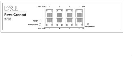
The following figure illustrates the PowerConnect 2708 front panel.
Figure 1-1. PowerConnect 2708 Front Panel
The PowerConnect 2708 switch supports 8 GbE copper ports.
7
16 1-Gigabit Ethernet Ports
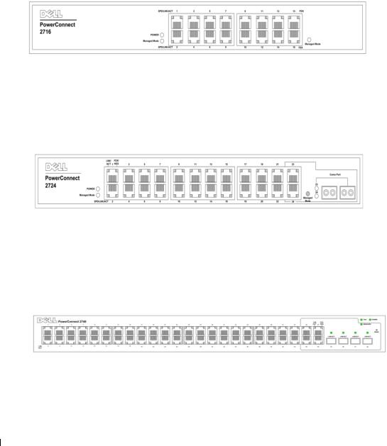
The following figure illustrates the PowerConnect 2716 front panel.
Figure 1-2. PowerConnect 2716 Front Panel
The PowerConnect 2716 switch supports 16 GbE copper ports.
24 1-Gigabit Ethernet Ports + 2 SFP Combo ports
The following figure illustrates the PowerConnect 2724 front panel.
Figure 1-3. PowerConnect 2724 Front Panel
The PowerConnect 2724 switch supports 24 GbE copper ports and has two SFP combo ports (1000BASE-SX or 1000BASE-LX).
48 1-Gigabit Ethernet Ports
The following figure illustrates the PowerConnect 2748 front panel.
Figure 1-4. PowerConnect 2748 Front Panel
8

Features
General Features
Head of Line Blocking Prevention
Head of Line (HOL) blocking results in traffic delays and frame loss caused by traffic competing for the same egress port resources. HOL blocking queues packets, and the packets at the head of the queue are forwarded before packets at the end of the queue. By default, the device is configured so that the HOL blocking prevention mechanism is active at all times, except when QoS (Quality of Service), Flow Control or Back Pressure is active on a port where the HOL blocking prevention mechanism is disabled on the whole system.
Management Modes
•Unmanaged Mode — Operates independent of user-configuration. The switch does not have an IP address, nor is there a web management interface and thus cannot be managed. This is the system default. From Unmanaged Mode, when the Managed Mode button is pressed, the switch enters Managed Mode with the default IP address of 192.168.2.1.
•Managed Mode — Provides switch management through a web interface, and maintains the device configuration through power cycles. From Managed Mode, when the Managed Mode button is pressed, the switch enters Unmanaged Mode.
•Secure Mode (PowerConnect 2748 only) — Secure Mode works by the user configuring the switch in Managed Mode and then enabling Secure Mode. Once enabled, it prevents users from making any further configuration changes to the switch. This is done by removing the IP address to the switch so that it becomes inaccessible. In Secure Mode the switch retains configuration through power cycles just like Managed Mode. To use Secure Mode, the user puts the switch in Managed Mode, configures the switch as desired, and then switches to Secure Mode via the web interface. To exit Secure Mode, the user presses the Managed Mode button. From Secure Mode when the Managed Mode button is pressed, the switch enters Managed Mode default configuration with the default IP address of 192.168.2.1.
Back Pressure Support
On half-duplex links, the receiving port prevents buffer overflows by occupying the link so that it is unavailable for additional incoming traffic. The user may enable or disable this feature on a per-port basis. The default status on all ports is set to OFF. However, this applies to links operating at Half Duplex only.
9

Auto Negotiation
Auto negotiation allows an Ethernet switch to advertise modes of operation. The auto negotiation function provides the means to exchange information between two Ethernet switches that share a point-to-point link segment, and to automatically configure both Ethernet switches to take maximum advantage of their transmission capabilities. Port advertisement allows the system administrator to configure the port speeds advertised.
Jumbo Frames Support
Jumbo frames are frames with an MTU (Maximum Transmission Unit) size of up to 10K bytes. The Jumbo Frames Support feature, utilizes the network optimally by transporting the same data using less frames.
The main benefits of this facility are reduced transmission overhead and reduced host processing overhead. Jumbo frames are used for server-to-server transfers.
AutoMDI/MDIX Support
The switch automatically detects whether the cable connected to an RJ-45 port is crossed or straight through.
Standard wiring for end stations is Media-Dependent Interface (MDI) and the standard wiring for hubs and switches is known as Media-Dependent Interface with Crossover (MDIX).
Auto MDI/MDIX works on 10/100/1000BASE-T Ethernet ports. This feature is automatically enabled for the entire system and cannot be turned off by the user.
Flow Control Support (IEEE802.3X)
On Full Duplex links (FDX), the flow control mechanism allows the receiving side to signal to the sending side that transmission must be halted temporarily, in order to prevent buffer overflows.
Virtual Cable Testing (VCT)
VCT technology provides the mechanism to detect and report potential cabling issues, such as cable opens and cable shorts on copper links.
Cable analysis is available on Copper Cables (10BASE-T/100BASE-T/1000BASE-T), and is only done when the link is down. When the system initiates a cable-testing operation, upon explicit user action, the following parameters are detected:
•Cable Type and Status
•Cable Length
•Fault-Distance
10
MAC Address Supported Features
MAC Address Capacity Support
The PowerConnect 2708, 2716, and 2724 switches support a total of 8K MAC addresses, and the PowerConnect 2748 supports a total of 16K MAC addresses.
Auto-Learning MAC Addresses
The switch enables MAC address auto-learning from incoming packets. The MAC addresses are stored in the Bridging Table.
Automatic Aging for MAC Addresses
MAC addresses from which no traffic is received for a given period of time are aged out. This prevents the Bridging Table from overflowing.
Managed and Secure Modes VLAN-aware MAC-based Switching
In Managed or Secure mode, the switch system always performs VLAN-aware bridging. Classic bridging (IEEE802.1D) is not performed (where frames are forwarded based only on their destination MAC address). However, a similar functionality may be configured for untagged frames. Addresses are associated with ports by learning them from the incoming frames source address.
Unmanaged Mode Classic Bridging
In Unmanaged Mode, the switch performs classic bridging. Frames are forwarded based on their destination MAC address only, regardless of the VLAN tag.
Layer 2 Features
Port Mirroring
The port mirroring mechanism monitors and mirrors network traffic by forwarding copies of incoming and outgoing packets from a monitored port to a monitoring port. Users can specify which target port receives copies of all traffic passing through one or more source ports.
Storm Control
Storm Control enables limiting the amount of Multicast and Broadcast frames accepted and forwarded by the switch. When Layer 2 frames are forwarded, Broadcast and Multicast frames are flooded to all ports on the relevant VLAN. All nodes connected to these ports accept and attempt to process these frames, thus placing load on both the network links and the host operating system.
11

VLAN Supported Features
VLAN Support
VLANs are collections of switching ports that comprise a single broadcast domain. Packets are classified as belonging to a VLAN based on either the VLAN tag or based on a combination of the ingress port and package contents. Packets sharing common attributes can be grouped in the same VLAN.
Port Based Virtual LANs (VLANs)
Port-based VLANs classify incoming packets to VLANs based on their ingress port.
Link Aggregation
The PowerConnect 2708/2716/2724/2748 switches support up to six aggregated links. Each of the six aggregated links may be defined with up to four member ports to form a single Link Aggregated Group (LAG).
The benefits of this facility are:
•Fault tolerance protection from physical link disruption
•Higher bandwidth connections
•Improved bandwidth granularity
•High bandwidth server connectivity
A LAG is composed of ports with the same speed set to full-duplex operation.
BootP and DHCP Clients
DHCP (Dynamic Host Configuration Protocol) enables additional setup parameters to be received from a network server upon system startup. DHCP service is an on-going process. DHCP is an extension to BootP.
The BootP client is operational if there is a corrupted or invalid software image. The BootP client then continuously attempts to find a BootP server, by sending BootP requests to all ports on the default VLAN, until a BootP server replies. The information replied is then used to provide the switch system with a TFTP server IP address and a download file name. The switch can then configure these values to the TFTP client and try to download a valid runtime image.
Class of Service (CoS) Features
The PowerConnect 2708/2716/2724/2748 system enables users to define various services for traffic classes of service. The underlying mechanism for supporting bandwidth management and control is based on the use of multiple priority queues for classifying traffic. The switches support four queues per port.
12

A CoS is defined by the user, whereby packets are related to the same Class of Service. After a packet has been classified, it is assigned to one of the queues. The PowerConnect 2708/2716/2724/2748 system can classify according to IPv4 information (DSCP).
Class Of Service 802.1p Support
The IEEE 802.1p signaling technique is an OSI Layer 2 standard for marking and prioritizing network traffic at the data link/MAC sub-layer. 802.1p traffic is classified and sent to the destination. No bandwidth reservations or limits are established or enforced. The 802.1p is a spinoff of the 802.1Q (VLANs) standard.
Ethernet Switch Management Features
Web-Based Management
With a Web-based management interface, the Ethernet Switches’ system can be managed from any Web browser. The system contains an Embedded Web Server (EWS), which serves HTML pages, through which the system can be monitored and configured.
TFTP Trivial File Transfer Protocol
The PowerConnect 2708/2716/2724/2748 switches support software boot image and software download through TFTP.
Remote Monitoring
Remote Monitoring (RMON) is an extension to the Simple Network Management Protocol (SNMP), which provides network traffic statistics. RMON defines current and historical MAClayer statistics and control objects, allowing real-time information to be captured across the entire network. The switches support one RMON group for Ethernet statistics. The system provides a means to collect the statistics defined in RMON and to view the results, using the Web management interface in the system.
Port Default Settings
The PowerConnect 2708/2716/2724/2748 devices’s port default settings are as follows:
Function |
Default Setting |
Flow Control (user-configurable) |
Off (disabled on ingress) |
|
|
Backpressure (user-configurable) |
Off (disabled on ingress) |
|
|
Auto Negotiation Speed (user-configurable) |
Enabled (1000 Mbps) |
|
|
Auto Negotiation Duplex (user-configurable) |
Enabled (Full Duplex) |
|
|
MDIX (not user-configurable) |
On (relevant to copper ports only) |
|
|
13

14
2
Hardware Description
Switch Port Configurations
PowerConnect 2708/2716/2724/2748 Front Panel Port Description
The Dell™ PowerConnect™ 2708, 2716, 2724 and 2748 switches use 10/100/1000BASE-T ports on the front panel for connecting to a network.
The Gigabit Ethernet ports can operate at 10, 100 or 1000 Mbps. These ports support autonegotiation, duplex mode (Half or Full duplex), and flow control. The combo 1000 Mbps optical ports can only operate at 1000 Mbps, full-duplex mode.
The following figures illustrate the front panels and back panels of the PowerConnect 2708/2716/2724/2748 switches.
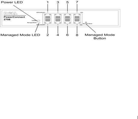
Figure 2-1. PowrConnect 2708 Front Panel
On the front panel there are eight ports which are numbered 1 to 8, top down and left to right. On each port there are LEDs (Light Emitting Diode) to indicate the port status.
On the left side of the front panel is the Managed Mode LED which indicates the Ethernet switch operational status. The Power LED on the front panel indicates whether the device is powered on or not. A Managed Mode push-button, located on the right side on the front panel, restores the device’s default settings configuration.
15
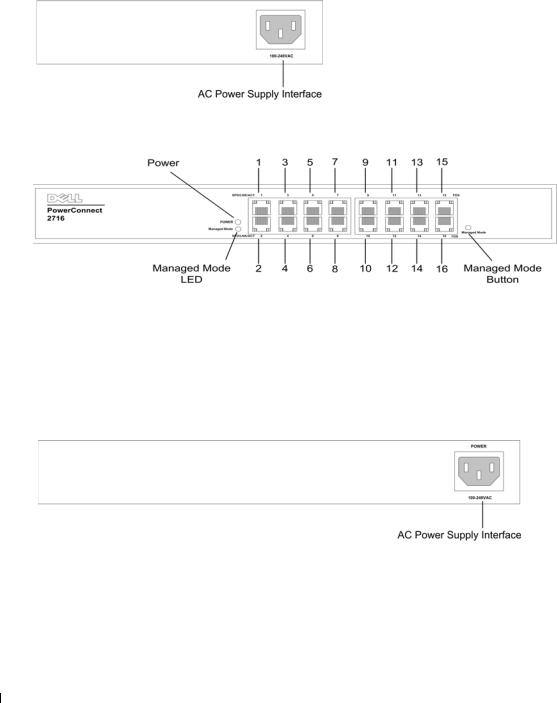
Figure 2-2. PowerConnect 2708 Back Panel
Figure 2-3. PowerConnect 2716 Front Panel
On the front panel, there are 16 ports, which are numbered 1 to 16, top down and left to right. On each port there are LEDs to indicate the port status.
On the left side of the front panel is the Managed Mode LED which indicates the Ethernet switch operational status. The Power LED on the front panel indicates whether the device is powered on or not. A Managed Mode push-button, located on the right side on the front panel, restores the device’s default settings configuration.
Figure 2-4. PowerConnect 2716 Back Panel
16

Figure 2-5. PowerConnect 2724 Front Panel
On the front panel there are 24 ports which are numbered 1 to 24, top down and left to right. On each port there are LEDs to indicate the port status. There are two SFP (Small Form-Factor Plugable) ports, designated as ports 23 and 24, for fiber connection. The two combo ports are logical ports with two physical connections:
•An RJ-45 connection for Twisted Pair (TP) copper cabling
•An SFP port for swappable optical transceiver, which offers high-speed 1000BASE-SX or 1000BASE-LX connection.
NOTE: Only one of the two physical connections of a combo port can be used at any one time. Port features and port controls are determined by the physical connection used. The system automatically detects the media used on a combo port, and utilizes the information in all the control interfaces.
NOTE: The system can switch from the RJ-45 to the SFP (or vice versa) without resetting the device. If both RJ-45 and SFP ports are present, the SFP port will be the active port, whereas the RJ-45 port will be disabled.
On the left side of the front panel is the Managed Mode LED which indicates the Ethernet switch operational status. The Power LED on the front panel indicates whether the device is powered on or not. A Managed Mode push-button, located on the far right side on the front panel, restores the device’s default settings configuration.
Figure 2-6. PowerConnect 2724 Back Panel
17
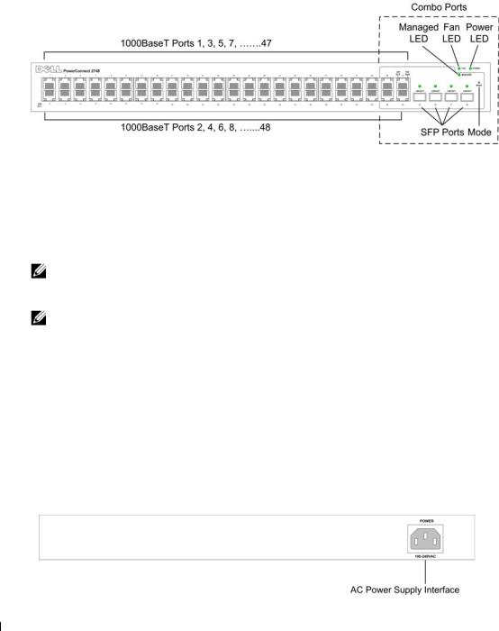
Figure 2-7. PowerConnect 2748 Front Panel
On the front panel, there are 48 ports, which are numbered 1 to 48, top down and left to right. On each port, there are LEDs to indicate the port status. There are four SFP (Small FormFactor Plugable) ports, designated as ports 45, 46, 47 and 48, for fiber connection. The four combo ports are logical ports with two physical connections:
•An RJ-45 connection for Twisted Pair (TP) copper cabling.
•An SFP port for swappable optical transceiver, which offers high-speed 1000BASE-SX or 1000BASE-LX connection.
NOTE: Only one of the two physical connections of a combo port can be used at any one time. Port features and port controls are determined by the physical connection used. The system automatically detects the media used on a combo port, and utilizes the information in all the control interfaces.
NOTE: The system can switch from the RJ-45 to the SFP (or vice versa) without resetting the device. If both RJ-45 and SFP ports are present, the SFP port will be the active port, whereas the RJ-45 port will be disabled.
On the top right side of the front panel is the Managed Mode LED, which indicates the Ethernet switch operational status. The Fan LED indicates the device fan operations status and the Power LED on the front panel indicates whether the device is powered on or not. A Managed Mode push-button, located on the far right side on the front panel, sets the device management mode.
The back panel contains an AC Power Supply Interface.
The following figure illustrates the back panel of the PowerConnect 2748 device.
Figure 2-8. PowerConnect 2748 Back Panel
18

Physical Dimensions
The PowerConnect 2708 switch has the following physical dimensions:
•Height — 43.2 mm (1.7008 in.)
•Width — 256 mm (10.079 in.)
•Depth — 161.7 mm (6.366 in.)
The PowerConnect 2716 and PowerConnect 2724 switches have the following physical dimensions:
•Height — 43.2 mm (1.7008 in.)
•Width — 330 mm (12.992 in.)
•Depth — 230.50 mm (9.075 in.)
The PowerConnect 2748 switch has the following physical dimensions:
•Height — 43.2 mm (1.70 in.)
•Width — 440 mm (17.32 in)
•Depth — 255 mm (10.04 in.)
LED Definitions
The front panel contains LEDs that indicate the status of links, power supply, fan status, and Managed Mode status.
Power LED
On the PowerConnect 2708/2716/2724/2748 front panel there is a Power LED. The following table describes the Power Supply status LED indications.
Table 2-1. Power LED Indications
LED Color |
Description |
|
|
Green Solid |
The switch is turned on. |
Off |
The switch is not turned on. |
|
|
Managed Mode LED
On the PowerConnect 2708/2716/2724/2748 front panel there is a Managed Mode LED monitoring the switch node as well as indicating diagnostic test results. The following table describes the Managed Mode LED indications.
19
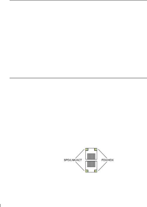
Table 2-2. Managed Mode LED Indications
LED Color |
Description |
|
|
Green Flashing |
Indicates diagnostics in progress, firmware loading, or Managed Mode |
|
transition. |
Green Solid |
Indicates the switch is in Managed Mode. |
Amber Solid |
Diagnostics has failed. |
Amber Flashing |
No valid image. |
Off |
Indicates Unmanaged mode or Secure mode (2748 only). |
|
|
Fan LED (2748 only)
On the PowerConnect 2748 front panel there is a fan LED. The following table describes the fan status LED indications.
Table 2-3. Fan LED Indications
LED Color |
Description |
|
|
Green Solid |
All fans are operating correctly. |
Red Solid |
One or more fans have failed. |
|
|
Port LEDs
10/100/1000BASE-T Port LEDs
Each 10/100/1000BASE-T port has two LEDs. Speed/Link/Activity is indicated on the left LED and the duplex mode is indicated on the right LED.
The following figure illustrates the RJ-45 10/100/1000BASE-T LEDs.
Figure 2-9. RJ-45 Copper-based 10/100/1000BASE-T LEDs
The RJ-45 LED indications are described in the following table:
20
Table 2-4. RJ-45 Copper based 10/100/ 1000BASE-T LED Indications
LED |
Color |
Description |
|
|
|
Left LED |
Green Static |
The port is linked at 1000 Mbps. |
|
Green Flashing |
The port is transmitting or receiving data at 1000 Mbps. |
|
Amber Static |
The port is linked at either 10 or 100 Mbps. |
|
Amber Flashing |
The port is transmitting or receiving data at 10 or 100 Mbps. |
|
Off |
The port is currently not operating |
Right LED |
Green Static |
The port is currently transmitting in Full Duplex mode. |
|
Off |
The port is operating in Half Duplex mode. |
|
|
|
SFP Port LED
The following table describes the SFP LED indications.
Table 2-5. SFP LED Indications
LED Color |
Description |
|
|
Green Static |
Link is established. |
Green Flashing |
Activity is occurring. |
Off |
No link is established. |
|
|
Managed Mode Button
The PowerConnect 2708/2716/2724/2748 has a Managed Mode push button on the front panel. The Managed Mode button is for changing between Managed Mode and Unmanaged (or Secure) Mode. After a change from Unmanaged (or Secure) Mode to Managed Mode, the switch restores the configuration values to factory default settings.
From Unmanaged or Secure Mode (2748 only), pressing the Managed Mode button causes:
•Factory default configuration (192.168.2.1) is set as the switch IP address.
•Subnet mask changes to 255.255.255.0
•Graphical User Interface (GUI) login user name changes to Admin, and the password is not configured (appears blank), with Read/Write privilege.
•The DHCP client is set off.
•The device is rebooted.
21
Switch Ventilation Fan
The PowerConnect 2748 switch has three fans and the PowerConnect 2724 switch has one fan for system ventilation. The PowerConnect 2708 and PowerConnect 2716 devices have no internal fans.
Cables, Port Connections, and Pinout Information
This section explains the switch physical interfaces, and provides information about cables and port connections. Copper cable diagnostics are supported. High-speed workstations, hubs, routers, or other switches are connected through standard RJ-45 connectors to the switch physical interface ports, located on the front panel. For each device, the supported mode is set to Half Duplex, Full Duplex, and Auto.
1000BASE-T Cable Requirements
All Category 5 UTP cables that are used for 100BASE-TX connections also operate with 1000BASE- T, provided if all four wire pairs are connected. However, it is recommended that enhanced Category 5 (Category 5e)cable is used for all critical connections or any new cable installations. The Category 5e specification includes test parameters that are only recommendations for Category 5, and comply with the IEEE 802.3ab standards.
RJ-45 Connections for 10/100/1000BASE-T Ports
The 10/100/1000BASE-T ports are copper Twisted-Pair ports.
Table 2-6. Ports, Connectors and Cables
Connector |
Port/Interface |
Cable |
|
|
|
RJ-45 |
10/100/1000BASE-T Port |
Cat.5 |
|
|
|
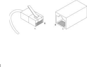
The following figure illustrates the RJ-45 pin connector pin numbers.
Figure 2-10. RJ-45 Pin Numbers
The RJ-45 pin number allocation for the 10/100/1000BASE-T ports is listed in the following table.
22

Table 2-7. |
RJ-45 Pin Number Allocation for 10/100/ 1000BASE-T Ethernet Port |
Pin No |
Function |
1TxRx 1+
2TxRx 1-
3TxRx 2+
4TxRx 2-
5TxRx 3+
6TxRx 3-
7TxRx 4+
8TxRx 4-
SFP Ports
The PowerConnect 2724 switch supports two SFP transceivers combo ports, and the PowerConnect 2748 switch supports four SFP transceivers combo ports for various fiber-based modules (1000BASE-SX or 1000BASE-LX). Only one of the two physical connections of a combo port can be used at any time. The system can switch from the RJ-45 to the SFP (or vice versa) without a system reset. The system automatically detects the media used on a combo port, and utilizes this information in the control interfaces.
PowerConnect 2724 switch supports SFP diagnostics. The optical transceiver provides access to a set of parameters that can be monitored and displayed to the system administrator.
NOTE: If both RJ-45 and SFP ports are present, the SFP port will be the active port, whereas the RJ-45 port will be disabled and ignored.
23

Pin Connections for SFP Interfaces
Table 2-8. SFP Pin Connections
Pin No |
Use |
|
|
1 |
Transmitter ground (common with receiver ground) |
|
|
2 |
Transmitter fault |
|
|
3 |
Transmitter disable; laser output disabled on high or open. |
|
|
4 |
Module definition 2; data line for serial ID. |
|
|
5 |
Module definition 1; clock line for serial ID. |
|
|
6 |
Module definition 0; grounded within the module. |
|
|
7 |
Rate select; no connection required. |
|
|
8 |
Loss of signal indication; logic 0 indicates normal operation. |
|
|
9 |
Receiver ground (common with transmitter ground) |
|
|
10 |
Receiver ground (common with transmitter ground) |
|
|
11 |
Receiver ground (common with transmitter ground) |
|
|
12 |
Receiver inverted data out; AC coupled. |
|
|
13 |
Receiver non-inverted data out; AC coupled. |
|
|
14 |
Receiver ground (common with transmitter ground) |
|
|
15 |
Receiver power supply |
|
|
16 |
Transmitter power supply |
|
|
17 |
Transmitter ground (common with receiver ground) |
|
|
18 |
Transmitter non-inverted data in |
|
|
19 |
Transmitter inverted data in |
|
|
20 |
Transmitter ground (common with receiver ground) |
|
|
Power Connectors
The PowerConnect 2708/2716/2724/2748 switches are powered by using the AC internal power supply.
Internal Power Supply Connector
The PowerConnect 2708, PowerConnect 2716, PowerConnect 2724 and PowerConnect 2748 switch systems supports a single internal power supply to provide power for switching operations. The internal power supply supports input voltages between 100 and 240 VAC. The AC power connector is located on the back panel of the switch.
24

3
Installing the Dell™ PowerConnect™ 27XX
This chapter contains information about unpacking, installation procedures, and how to make cable and port connections for the PowerConnect 2708, 2716, 2724, and 2748 devices.
Installation Precautions
 CAUTION: Before performing any of the following procedures, read and follow the safety instructions located in the Product Information Guide.
 CAUTION: Observe the following points before performing the procedures in this section:
•Observe and follow the service markings. Do not service any Ethernet device except as explained in the system documentation. Opening or removing covers marked with a triangular symbol with a lighting bolt may cause electrical shock. These components are to be serviced by trained service technicians only.
•Ensure that the Ethernet device is not exposed to water.
•Ensure that the Ethernet device is not exposed to radiators or heat sources.
•Do not push foreign objects into the device’s hardware enclosure, as it may cause a fire or electric shock.
•Use the Ethernet device only with approved equipment.
•Allow the Ethernet device to cool before removing covers or touching internal equipment.
•Ensure that the airflow around the front, sides, and back of the device chassis is not restricted.
Overview
The PowerConnect 2708/2716/2724/2748 are standard 1U chassis high, 19-inch rack-mountable devices.
The process of installing the PowerConnect switch consists of both hardware and software instructions. The process consists of physically installing these devices and configuring them.
The switch is delivered from the factory in Unmanaged Mode. If the user wishes to use the switch as an unmanaged switch, they can simply plug the switch in and start using it. No configuration is necessary. If the user wishes to use the switch as a managed switch, they need to change the switch
25
to Managed Mode. The chapter "Starting and Configuring the Dell™PowerConnect™ 2708/2716/2724/2748 for Managed Mode Operation" explains how to set the switch to Managed Mode.
Site Requirements
The PowerConnect 2708/2716/2724/2748 devices can be mounted in a standard equipment rack, placed on a tabletop, or mounted on the wall.
Before installing the unit, verify that the site selected for the device meets the following site requirements:
•Power — The device is installed within 1.5 m (5 feet) of a grounded, easily accessible outlet 220/110 VAC, 50/60 Hz. If the device has two power supplies, the site should have two power outlets with different power feeders.
•General — Ensure that the power supply is correctly installed.
•Clearance — There is adequate frontal clearance for operator access. Allow clearance for cabling, power connections, and ventilation.
•Cabling — Cabling is routed to avoid sources of electrical noise such as radio transmitters, broadcast amplifiers, power lines, and fluorescent lighting fixtures.
•Ambient Requirements — The ambient unit operating temperature range is 0 to 45C (32 to 113F) at a relative humidity of up to 95%, non-condensing. Verify that water or moisture cannot enter the device case.
Unpacking
NOTE: Before unpacking the device, inspect the packaging and report any evidence of damage immediately to Dell.
Safety
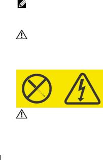
CAUTION: Never remove the cover on a power supply or any part that has the following label attached.
Figure 3-1. Caution Label
CAUTION: Hazardous voltage, current, and energy levels are present inside any component that has this label attached. There are no serviceable parts inside these components. If you suspect a problem with one of these parts, contact a service technician.
26
Loading...