


 Loading...
Dell™ PowerEdge™
1950 Systems
Information Update

Notes, Cautions, and Warnings
NOTE: A NOTE indicates important information that helps you make better use of your computer.
CAUTION: A CAUTION indicates potential damage to hardware or loss of data if instructions are not followed.
WARNING: A WARNING indicates a potential for property damage, personal injury, or death.
____________________
Information in this document is subject to change without notice. ©2006–2009 Dell Inc. All rights reserved.
Reproduction of these materials in any manner whatsoever without the written permission of Dell Inc. is strictly forbidden.
Trademarks used in this text: Dell, the DELL logo, and PowerEdge are trademarks of Dell Inc.; Intel and Xeon are registered trademarks of Intel Corporation; Microsoft, Windows, and Windows Server are either trademarks or registered trademarks of Microsoft Corporation in the United States and/or other countries; Red Hat and Red Hat Enterprise Linux are registered trademarks of Red Hat, Inc.; SUSE is a registered trademark of Novell Inc.
Other trademarks and trade names may be used in this document to refer to either the entities claiming the marks and names or their products. Dell Inc. disclaims any proprietary interest in trademarks and trade names other than its own.
November 2009 |
Rev. A09 |

Contents
Non-Optimal Memory Configurations . . . . . . . . . . . |
5 |
PowerEdge 1950 III – New System Features . . . . . . . |
5 |
New Performance Features . . . . . . . . . . . . . |
5 |
New High-Efficiency Power Supply |
|
and Power Monitoring Features . . . . . . . . . . . |
5 |
New I/O and Storage Features . . . . . . . . . . . . |
6 |
New Security Features . . . . . . . . . . . . . . . . |
6 |
Optional Internal USB Memory Key . . . . . . . . . . . . |
6 |
Installing the Optional Internal USB Memory Key . . 8 |
|
Support for 8-GB Memory Modules – |
|
PowerEdge 1950 III Systems . . . . . . . . . . . . . . . . |
9 |
Processor Upgrades – PowerEdge 1950 II |
|
and PowerEdge 1950 III Systems . . . . . . . . . . . . . |
9 |
System Board Replacement – |
|
Safeguarding Encrypted Data . . . . . . . . . . . . . . |
10 |
System Message Update. . . . . . . . . . . . . . . . . |
10 |
LCD Status Messages Update . . . . . . . . . . . . . . |
15 |
Contents 3

System Setup Program Update. . . . . . . . . . . . . . |
21 |
Memory Screen . . . . . . . . . . . . . . . . . . . |
21 |
CPU Information Screen . . . . . . . . . . . . . . |
22 |
Integrated Devices Screen . . . . . . . . . . . . . |
22 |
System Security Screen . . . . . . . . . . . . . . |
23 |
Operating System Information . . . . . . . . . . . . . . |
25 |
Enumeration of NICs . . . . . . . . . . . . . . . . |
25 |
RHEL – Incorrect Processor Information . . . . . . |
25 |
System Support for Microsoft Windows 2000 . . . |
25 |
Hardware Owner’s Manual Updates . . . . . . . . . . |
26 |
Installing the Processor. . . . . . . . . . . . . . . |
26 |
System Diagnostics Custom Test Options . . . . . |
26 |
4 Contents

Non-Optimal Memory Configurations
The POST may halt when a non-optimal memory configuration is detected and the following message is displayed:
Non-Optimal Memory Configuration
Press F1 to continue or F2 for Setup
NOTE: Mixing DIMMs of different speeds renders the memory configuration non6Hoptimal. The system clocks down the performance to the slowest speed in the DIMM set for the channel.
PowerEdge 1950 III – New System Features
New Performance Features
•Two dual-core or quad-core Intel® Xeon® 5400 Series and 5300 Series processors.
•8-GB memory module support.
New High-Efficiency Power Supply and Power Monitoring Features
•Higher system efficiency on power conversion across workloads.
•Baseboard Management Control (BMC) power monitoring monitors current, voltage, and power utilization in the system.
Information Update |
5 |
New I/O and Storage Features
•Optional Intel quad-port Gigabit Ethernet NIC, capable of supporting 10-Mbps, 100-Mbps, and 1000-Mbps data rates and iSCSI remote boot.
•Support for 10-Gb Ethernet cards.
•One internal USB 2.0-compliant connector supporting an optional bootable USB flash drive or USB memory key.
•Support for optional SAS 6i/R and PERC 6/i adapters.
New Security Features
•Trusted Program Module (TPM) support for improved security.
•Optional support for iSCSI boot.
Optional Internal USB Memory Key
The PowerEdge 1950 III system provides an internal USB connector located on the system board for use with a USB flash memory key (see Figure 1-1). The USB memory key can be used as a boot device, security key, or mass storage device. To use the internal USB connector, the Internal USB Port option must be enabled in the Integrated Devices screen of the System Setup program. See "Integrated Devices Screen" on page 22.
6 |
Information Update |
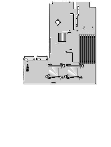
Figure 1-1. Internal USB Connector Location
 1
1
2 
|
|
|
|
|
|
|
|
|
|
|
|
|
|
|
|
|
|
|
|
|
|
|
|
|
|
|
|
|
|
|
|
|
|
|
|
|
|
|
|
|
|
|
|
|
|
|
|
|
|
|
|
|
|
|
|
|
|
|
|
|
|
|
|
|
|
|
|
|
|
|
|
|
|
|
|
|
|
|
|
|
|
|
|
|
|
|
|
|
|
|
|
|
|
|
|
|
|
|
|
|
|
|
|
|
|
|
|
|
|
|
|
|
|
|
|
|
|
|
|
|
|
|
|
|
|
|
|
|
|
|
|
|
|
|
|
|
|
|
|
|
|
|
|
|
|
|
|
|
|
|
|
|
|
|
|
|
|
|
|
|
|
|
|
|
|
|
|
|
|
|
|
|
|
|
|
|
|
|
|
|
|
|
|
|
|
|
|
|
|
|
|
|
|
|
|
|
|
|
|
|
|
|
|
|
|
|
|
|
|
|
|
|
|
|
|
|
|
|
|
|
|
|
|
|
|
|
|
|
|
|
|
|
|
|
|
|
|
|
|
|
|
|
|
|
|
|
|
|
|
|
|
|
|
|
|
|
|
|
|
|
|
|
|
|
|
|
|
|
|
|
|
|
|
|
|
|
|
|
|
|
|
|
|
|
|
|
|
|
|
|
|
|
|
|
|
|
|
|
|
|
|
|
|
|
|
|
|
|
|
|
|
|
|
|
|
|
|
|
|
|
|
|
|
|
|
|
|
|
|
|
|
|
|
|
|
|
|
|
|
|
|
|
|
|
|
|
|
|
|
|
|
|
|
|
|
|
|
|
|
|
|
|
|
|
|
|
|
1 |
system board |
2 |
|
internal USB connector location |
||||||||||||||||||
To boot from the USB memory key, you must configure the USB memory key with a boot image and then specify the USB memory key in the boot sequence in the System Setup program. See "Using the System Setup Program" in the Hardware Owner’s Manual. For information on creating
a bootable file on the USB memory key, see the user documentation that accompanied the USB memory key.
NOTE: USB keys that contain multiple LUNs (Logical Unit Numbers) must be formatted using the format utility provided by the key manufacturer.
NOTE: To avoid interference with components inside the system, the USB key must conform to the following maximum dimensions: 11.68mm thick (0.46") x 24.89mm width (0.98") x 66.8mm length (2.63").
Information Update |
7 |

Installing the Optional Internal USB Memory Key
WARNING: Only trained service technicians are authorized to remove the system cover and access any of the components inside the system. See your Product Information Guide for complete information about safety precautions,
working inside the computer, and protecting against electrostatic discharge.
1Turn off the system, including any attached peripherals, and disconnect the system from its electrical outlet.
2Open the system. See "Opening the System" in the Hardware Owner’s Manual.
3Remove the memory cooling shroud. See "Removing the Memory Cooling Shroud" in the Hardware Owner’s Manual.
4Locate the USB connector on the system board and insert the USB memory key into the USB connector. See Figure 1-2.
Figure 1-2. Installing an Internal USB Key
1
2
1 USB memory key |
2 internal USB connector |
8 |
Information Update |

5Replace the memory cooling shroud.
6Close the system. See "Closing the System" in the Hardware Owner’s Manual.
7Reconnect the system to power and restart the system.
8Enter the System Setup program and verify that the USB key has been detected by the system. See "Using the System Setup Program" in the
Hardware Owner’s Manual.
Support for 8-GB Memory Modules –
PowerEdge 1950 III Systems
PowerEdge 1950 III systems have added support for the following approved 8-GB memory configurations:
•64 GB — 8 x 8-GB quad-rank memory modules
•48 GB — 4 x 8-GB quad-rank and 4 x 4-GB dual-rank memory modules
If 64 GB of memory is installed, the system only recognizes and displays 63.75 GB during POST.
NOTE: Prior to upgrading your system, verify that the latest system BIOS version is on your system. Loading the latest BIOS version ensures that your system is fully supported.
NOTE: Some operating systems cannot support more than 4 GB of physical memory. For more information on memory support requirements and restrictions, refer to the operating system documentation that ships with your system.
Processor Upgrades – PowerEdge 1950 II and PowerEdge 1950 III Systems
•If the front of your system chassis is labeled with a "II," your system is upgradeable to the 5100 series of dual-core Intel Xeon processors and the 5300 series of quad-core Intel Xeon processors.
•If the front of your system chassis is labeled with a "III," your system is upgradeable to the 5100 and 5200 series of dual-core Intel Xeon processors and the 5300 and 5400 series of quad-core Intel Xeon processors.
See support.dell.com for information on the latest processor upgrade options for your system.
Information Update |
9 |

System Board Replacement – Safeguarding
Encrypted Data
On PowerEdge 1950 III systems using Windows Server® 2008, you can use encryption programs, such as the BitLocker utility, to secure the contents of the hard drive.
If you are using the TPM with an encryption application, you are prompted to create a recovery key during system setup. Be sure to store this recovery key. If you replace the system board, you must supply the recovery key when you restart your system before you can access the encrypted files on your hard drive(s).
System Message Update
Table 1-1 lists new system messages for the PowerEdge 1950 III system and the probable cause and corrective action when the message appears.
WARNING: Only trained service technicians are authorized to remove the system cover and access any of the components inside the system. See your Product Information Guide for complete information about safety precautions,
working inside the computer, and protecting against electrostatic discharge
10 |
Information Update |
Table 1-1. System Messages
Message |
Causes |
Corrective Actions |
|
|
|
Alert! Node |
The memory configuration |
Ensure that the memory |
Interleaving |
does not support node |
modules are installed in a |
disabled! Memory |
interleaving, or the |
configuration that supports |
configuration does |
configuration has changed |
node interleaving. Check |
not support Node |
(for example, a failed |
other system messages for |
Interleaving. |
DIMM) so that node |
additional information |
|
interleaving cannot be |
for possible causes. For |
|
supported. The system |
memory configuration |
|
runs but with reduced |
information, see "General |
|
functionality. |
Memory Module |
|
|
Installation Guidelines" |
|
|
in the Hardware Owner’s |
|
|
Manual. If the problem |
|
|
persists, see |
|
|
"Troubleshooting System |
|
|
Memory" in the Hardware |
|
|
Owner’s Manual. |
!!*** Error: Remote |
Remote Access Controller |
Ensure that the Remote |
Access Controller |
initialization failure. |
Access Controller is |
initialization |
|
properly installed. See |
failure *** RAC |
|
"Installing a RAC Card" |
virtual USB devices |
|
in the Hardware Owner’s |
may not be |
|
Manual. |
available... |
|
|
Invalid PCIe card |
The system halted because |
found in the |
an invalid PCIe expansion |
Internal_Storage |
card is installed in the |
slot! |
dedicated storage |
|
controller slot. |
No boot device |
Faulty or missing optical |
available |
drive subsystem, hard |
|
drive, or hard-drive |
|
subsystem, or no bootable |
|
USB key installed. |
Remove the PCIe expansion card and install the internal SAS controller in the dedicated slot.
Use a bootable USB key, CD, or hard drive. See "Using the System Setup Program" in the Hardware Owner’s Manual for information on setting the order of boot devices.
Information Update |
11 |

Table 1-1. System Messages (continued)
Message |
Causes |
Corrective Actions |
|
|
|
PCI BIOS failed to |
PCIe device BIOS (Option |
Reseat the expansion |
install |
ROM) checksum failure |
card(s). Ensure that all |
|
detected during shadowing. |
appropriate cables are |
|
Cables to expansion card(s) |
securely connected to the |
|
loose; faulty or improperly |
expansion card(s). If the |
|
installed expansion card(s). problem persists, see |
|
|
|
"Troubleshooting System |
|
|
Expansion Cards" in the |
|
|
Hardware Owner’s Manual. |
PCIe Degraded Link |
Faulty system board or riser |
See "Getting Help" in the |
Width Error: |
board. |
Hardware Owner’s Manual. |
Embedded device |
|
|
Expected Link Width |
|
|
is n |
|
|
Actual Link Width |
|
|
is n |
|
|
PCIe Degraded Link |
The specified PCIe device |
For a SAS controller |
Width Error: |
is faulty or improperly |
daughter card, reseat the |
Integrated device |
installed. |
card in the dedicated PCIe |
Expected Link Width |
|
connector. See "Installing a |
|
|
|
is n |
SAS Controller Daughter |
|
Card" in the Hardware |
||
Actual Link Width |
||
Owner’s Manual. If the |
||
is n |
||
problem persists, see |
||
|
||
|
"Getting Help" in the |
|
|
Hardware Owner’s Manual. |
PCIe Degraded Link |
Faulty or improperly |
Width Error: Slot n |
installed PCIe card in |
Expected Link Width |
the specified slot. |
is n |
|
Actual Link Width |
|
is n |
|
PCIe Training |
Faulty system board |
Error: Embedded |
or riser board. |
device |
|
Reseat the PCIe card in the specified slot number. See "Expansion Cards" in the
Hardware Owner’s Manual. If the problem persists, see "Getting Help" in the
Hardware Owner’s Manual.
See "Getting Help" in the
Hardware Owner’s Manual.
12 |
Information Update |

Table 1-1. System Messages (continued)
Message |
Causes |
Corrective Actions |
|
|
|
PCIe Training |
The specified PCIe device |
For a SAS controller |
Error: Integrated |
is faulty or improperly |
daughter card, reseat the |
device |
installed. |
card in the dedicated PCIe |
|
|
connector. See "Installing |
|
|
a SAS Controller Daughter |
|
|
Card" in the Hardware |
|
|
Owner’s Manual. If the |
|
|
problem persists, see |
|
|
"Getting Help" in the |
|
|
Hardware Owner’s Manual. |
PCIe Training |
Faulty or improperly |
Error: Slot n |
installed PCIe card in the |
|
specified slot. |
Reseat the PCIe card in the specified slot number. See "Expansion Cards" in the
Hardware Owner’s Manual. If the problem persists, see "Getting Help" in the
Hardware Owner’s Manual.
Remote Access |
RAC cables not connected, |
Controller cable |
or RAC card installed in |
error or incorrect |
wrong expansion slot. |
card in the RAC |
|
slot. |
|
Check that the RAC cables are connected, and that the RAC card is installed in the correct expansion slot. See "Installing a RAC Card" in the Hardware Owner’s Manual.
NOTE: All TPM information messages appear after the BMC option ROM has been loaded during POST.
TPM configuration |
System now resets. |
Information only. |
operation honored. |
|
|
TPM Failure |
A Trusted Platform Module |
See "Getting Help" in the |
|
(TPM) function has failed. |
Hardware Owner’s Manual. |
Information Update |
13 |

Table 1-1. System Messages (continued)
Message |
Causes |
Corrective Actions |
|
|
|
TPM operation is |
Configuration change has |
Press I to continue system |
pending. Press I to |
been requested. |
boot. Press M to modify |
Ignore or M to |
|
the TPM setting and |
Modify to allow |
|
restart. |
this change and |
|
|
reset the system. |
|
|
WARNING: Modifying |
|
|
could prevent |
|
|
security. |
|
|
Warning: Following |
Faulty or improperly seated |
|
faulty DIMMs are |
memory module(s). |
|
disabled: |
DIMMs are disabled in |
|
DIMM n1 n2 |
pairs, as indicated by the n1 |
|
and n2. Check both |
||
Total memory size |
||
DIMMs for a possible fault. |
||
is reduced. |
||
|
||
Warning: A fatal |
A fatal system error |
|
error has caused |
occurred and caused the |
|
system reset! |
system to restart. |
|
Please check the |
|
|
system event log! |
|
See "Troubleshooting
System Memory" in the
Hardware Owner’s Manual.
Check the SEL for information that was logged during the error. See the applicable troubleshooting section in See "Troubleshooting Your System" in the Hardware Owner’s Manual. for any faulty components specified in the SEL.
Warning! No |
micro |
Micro code update failed. Update the BIOS firmware. |
code update |
loaded |
See "Getting Help" in the |
for processor n |
Hardware Owner’s Manual. |
|
14 |
Information Update |

Table 1-1. System Messages (continued)
Message |
Causes |
Corrective Actions |
|
|
|
Warning: The |
Invalid memory |
Ensure that the memory |
installed memory |
configuration. The system |
modules are installed in a |
configuration is |
runs but with reduced |
valid configuration. See |
not optimal. For |
functionality. |
"General Memory Module |
more information on |
|
Installation Guidelines" |
valid memory |
|
in the Hardware Owner’s |
configurations, |
|
Manual. If the problem |
please see the |
|
persists, see |
system |
|
"Troubleshooting System |
documentation on |
|
Memory" in the Hardware |
the technical |
|
Owner’s Manual. |
support web site. |
|
|
Write fault
Write fault on selected drive
Faulty USB device, USB medium, optical drive assembly, hard drive, or hard-drive subsystem.
Replace the faulty media. Reseat the USB device or USB cable. For hard drive problems, see "Troubleshooting a Hard Drive" in the Hardware Owner’s Manual.
LCD Status Messages Update
Table 1-2 lists updates to the LCD status messages that can occur on the PowerEdge 1950 III system and the probable cause for each message.
The LCD messages refer to events recorded in the system event log (SEL). For information on the SEL and configuring system management settings, see your systems management software documentation.
Information Update |
15 |

Table 1-2. LCD Status Messages
Code |
Text |
Causes |
Corrective Actions |
|
|
|
|
N/A |
SYSTEM NAME |
A 62-character |
This message is for |
|
|
string that can be |
information only. |
|
|
defined by the user |
You can change the |
|
|
in the System Setup |
system ID and |
|
|
program. |
name in the System |
|
|
|
|
|
|
The SYSTEM NAME |
Setup program. See |
|
|
is displayed under |
"Using the System |
|
|
the following |
Setup Program" in |
|
|
conditions: |
the Hardware |
|
|
• The system is |
Owner’s Manual. |
|
|
|
|
|
|
powered on. |
|
|
|
• The power is off |
|
|
|
and active errors |
|
|
|
are displayed. |
|
E1000 |
FAILSAFE, Call |
Check the system |
See "Getting Help" |
|
Support |
event log for critical |
in the Hardware |
|
|
failure events. |
Owner’s Manual. |
E1118 |
CPU Temp |
The BMC is unable |
Turn off power to |
|
Interface |
to determine |
the system and |
|
|
the CPU(s) |
restart the system. |
|
|
temperature status. |
If the problem |
|
|
Consequently, the |
persists, see |
|
|
BMC increases |
"Getting Help" |
|
|
the CPU fan speed |
in the Hardware |
|
|
to maximum |
Owner’s Manual. |
|
|
as a precautionary |
|
|
|
measure. |
|
E1211 |
ROMB Batt |
RAID battery is |
Reseat the RAID |
|
|
either missing, bad, |
battery connector. |
|
|
or unable to |
See the "RAID |
|
|
recharge due to |
Battery" and see |
|
|
thermal issues. |
"Troubleshooting |
|
|
|
System Cooling |
Problems" in the
Hardware Owner’s
Manual.
16 |
Information Update |

Table 1-2. LCD Status Messages (continued)
Code |
Text |
Causes |
Corrective Actions |
|
|
|
|
E1625 |
PS AC Current |
Power source is out |
Check the AC |
|
|
of acceptable range. |
power source. |
E1711 |
PCI PERR B## |
The system BIOS |
Remove and reseat |
|
D## F## |
has reported a PCI |
the PCIe expansion |
|
|
parity error on a |
cards. If the |
|
|
component that |
problem persists, |
|
|
resides in PCI |
see |
|
|
configuration space |
"Troubleshooting |
|
|
at bus ##, device |
an Expansion Card" |
|
|
##, function ##. |
in the Hardware |
|
|
|
Owner’s Manual. |
|
PCI PERR Slot |
The system BIOS |
Reinstall the |
|
# |
has reported a PCI |
expansion-card riser. |
|
|
parity error on a |
See "Expansion |
|
|
component that |
Card Risers" in the |
|
|
resides in the |
Hardware Owner’s |
|
|
specified PCIe slot. |
Manual. |
If the problem persists, the riser card or system board is faulty. See "Getting Help"
in the Hardware Owner’s Manual.
Information Update |
17 |

Table 1-2. LCD Status Messages (continued)
Code |
Text |
Causes |
Corrective Actions |
|
|
|
|
E1712 |
PCI SERR B## |
The system BIOS |
Remove and reseat |
|
D## F## |
has reported a PCI |
the PCIe expansion |
|
|
system error on a |
cards. If the |
|
|
component that |
problem persists, |
|
|
resides in PCI |
see |
|
|
configuration space |
"Troubleshooting |
|
|
at bus ##, device |
Expansion Cards" |
|
|
##, function ##. |
in the Hardware |
|
|
|
Owner’s Manual. |
|
PCI SERR |
The system BIOS |
Reinstall the |
|
Slot # |
has reported a PCI |
expansion-card riser. |
|
|
system error on a |
See "Expansion |
|
|
component that |
Card Risers" in the |
|
|
resides in the |
Hardware Owner’s |
|
|
specified slot. |
Manual. |
|
|
|
If the problem |
|
|
|
persists, the riser |
|
|
|
card or system board |
|
|
|
is faulty. See |
|
|
|
"Getting Help" |
|
|
|
in the Hardware |
|
|
|
Owner’s Manual. |
18 |
Information Update |

Table 1-2. LCD Status Messages (continued)
Code |
Text |
Causes |
Corrective Actions |
|
|
|
|
E171F |
PCIE Fatal Err |
The system BIOS |
Remove and reseat |
|
B## D## F## |
has reported a PCIe |
the PCIe expansion |
|
|
fatal error on a |
cards. If the |
|
|
component that |
problem persists, |
|
|
resides in PCIe |
see |
|
|
configuration space |
"Troubleshooting |
|
|
at bus ##, device |
Expansion Cards" |
|
|
##, function ##. |
in the Hardware |
|
|
|
Owner’s Manual. |
|
PCIE Fatal Err |
The system BIOS |
Reinstall the |
|
Slot # |
has reported a PCIe |
expansion-card riser. |
|
|
fatal error on a |
See "Expansion |
|
|
component that |
Card Risers" in the |
|
|
resides in the |
Hardware Owner’s |
|
|
specified slot. |
Manual. |
|
|
|
If the problem |
|
|
|
persists, the riser |
|
|
|
card or system board |
|
|
|
is faulty. See |
|
|
|
"Getting Help" |
|
|
|
in the Hardware |
|
|
|
Owner’s Manual. |
E1914 |
DRAC5 Conn2 |
DRAC 5 cable is |
Reconnect the |
|
Cbl |
missing or |
cable. See |
|
|
disconnected. |
"Installing a RAC |
|
|
|
Card" in the |
|
|
|
Hardware Owner’s |
|
|
|
Manual. |
E1B01 |
USB# |
Device plugged in |
Reseat the device |
|
Overcurrent |
the specified USB |
cable. If the |
|
|
port caused an |
problem persists, |
|
|
overcurrent |
replace or remove |
|
|
condition. |
the device. |
Information Update |
19 |

Table 1-2. LCD Status Messages (continued)
Code |
Text |
Causes |
Corrective Actions |
|
|
|
|
E2110 |
MBE DIMM # & # One of the two |
See |
|
|
|
indicated DIMMs |
"Troubleshooting |
|
|
has had a memory |
System Memory" |
|
|
multi-bit error |
in the Hardware |
|
|
(MBE). |
Owner’s Manual. |
E2111 |
SBE Log |
The system BIOS |
See |
|
Disable DIMM # has disabled |
"Troubleshooting |
|
|
|
memory single-bit |
System Memory" |
|
|
error (SBE) logging, |
in the Hardware |
|
|
and does not |
Owner’s Manual. |
|
|
resume logging |
|
|
|
further SBEs until |
|
|
|
the system is |
|
|
|
restarted. "#" |
|
|
|
represents the |
|
|
|
DIMM implicated |
|
|
|
by the BIOS. |
|
E2112 |
Mem Spare |
The system BIOS |
See |
|
DIMM # |
has spared the |
"Troubleshooting |
|
|
memory because it |
System Memory" |
|
|
has determined that |
in the Hardware |
|
|
the memory had too |
Owner’s Manual. |
|
|
many errors. "# & |
|
|
|
#" represents the |
|
DIMM pair implicated by the BIOS.
I1915 |
Video Off |
|
(LCD lights with |
|
a blue or amber |
|
background.) |
I1916 |
Video Off |
|
in ## |
(LCD lights with a blue or amber background.)
The video has been |
Information only. |
turned off by the |
|
RAC remote user. |
|
The video was |
Information only. |
turned off in xx |
|
seconds by the RAC |
|
remote user. |
|
20 |
Information Update |
System Setup Program Update
Memory Screen
Table 1-3 lists the descriptions for the information fields that appear on the Memory Information screen.
Table 1-3. Memory Information Screen Options
Option |
Description |
|
|
System Memory Size |
Displays the amount of system memory. |
System Memory Type |
Displays the type of system memory. |
System Memory Speed |
Displays the system memory speed. |
Video Memory |
Displays the amount of video memory. |
System Memory Testing |
Specifies whether system memory tests are run at system |
|
boot. Options are Enabled and Disabled. |
Redundant Memory |
Enables or disables the redundant memory feature. |
(Disabled default) |
When set to Spare Mode, the first rank of memory on |
|
each DIMM is reserved for memory sparing. Redundant |
|
memory feature is disabled if the Node Interleaving field |
|
is enabled. |
Node Interleaving |
If this field is set to Enabled, memory interleaving is |
(Disabled default) |
supported if a symmetric memory configuration is |
|
installed. If this field is set to Disabled, the system can |
|
support Non-Uniform Memory architecture (NUMA) |
|
(asymmetric) memory configurations. |
|
NOTE: The Node Interleaving field must be set to Disabled |
|
when using the redundant memory feature. |
Low Power Mode |
Enables or disables the low power mode of the memory. |
(Disabled default) |
When set to Disabled, the memory runs at full speed. |
|
When set to Enabled, the memory runs at a reduced |
|
speed to conserve energy. |
|
|
Information Update |
21 |

CPU Information Screen
Table 1-4 updates the description for the Demand-Based Power Management option.
Table 1-4. CPU Information Screen
Option |
Description |
|
|
Demand-Based Power |
NOTE: Check your operating system documentation to |
Management |
verify if the operating system supports this feature. |
(Enabled default) |
Enables or disables demand-based power management. |
|
|
|
When enabled, the CPU Performance State tables are |
|
reported to the operating system; when disabled, the |
|
CPU Performance State tables are not reported to the |
|
operating system. If any of the CPUs do not support |
|
demand-based power management, the field becomes |
|
read-only, and is automatically set to Disabled. |
|
|
Integrated Devices Screen
Table 1-5 lists new Integrated Devices screen options.
Table 1-5. Integrated Devices Screen Options
Option |
Description |
|
|
Internal USB Port |
Enables or disables the system’s internal USB port. |
(On default) |
NOTE: You can only enable the internal USB port if the User |
|
|
|
Accessible USB Ports option on this screen is set to All ports |
|
On (the default value). |
OS Watchdog |
NOTE: This feature is usable only with operating systems that |
Timer |
support WDAT implementations of the Advanced Configuration |
(Disabled default) |
and Power Interface (ACPI) 3.0b specification. Microsoft® |
|
Windows Server® 2008 supports this feature, but Windows |
|
Server 2003 does not. |
|
Sets a timer that monitors the operating system for activity |
|
and aids in recovery if the system stops responding. When |
|
this field is set to Enabled, the operating system is allowed |
|
to initialize the timer. When set to Disabled, the timer is |
|
not initialized. |
22 |
Information Update |

Table 1-5. Integrated Devices Screen Options (continued)
Option |
Description |
|
|
I/OAT DMA |
Enables or disables the I/O Acceleration Technology (I/OAT) |
Engine |
option. When set to Enabled, I/OAT reduces system CPU |
(Disabled default) |
usage for applications that use TCP by offloading part of TCP |
|
receive operation to the DMA engine. |
System Interrupts |
This field controls the interrupt assignment for PCI devices |
Assignment |
in the system. When set to Distributed, interrupt routing is |
(Standard default) |
swizzled to minimize IRQ sharing among devices. |
|
|
System Security Screen
Table 1-6 lists new options for the PowerEdge 1950 III system.
NOTE: Systems that are shipping in China are not equipped with TPM.
CAUTION: Before enabling the TPM Security option, ensure that the operating system supports TPM.
Table 1-6. New System Security Screen Options
Option |
Description |
|
|
TPM Security |
Sets the reporting of the Trusted Platform Module |
(Off default) |
(TPM) in the system. |
|
When set to Off (default), presence of the TPM is |
|
not reported to the operating system. |
|
When set to On with Pre-boot Measurements, the |
|
system reports the TPM to the operating system and |
|
stores the pre-boot measurements (compliant with |
|
Trusted Computing Group standards) to the TPM during |
|
POST. |
|
When set to On without Pre-boot Measurements, the |
|
system reports the TPM to the operating system and |
|
bypasses pre-boot measurements. |
Information Update |
23 |

Table 1-6. New System Security Screen Options (continued)
Option |
Description |
|
|
TPM Activation |
Changes the operational state of the TPM. |
|
When set to Activate, the TPM is enabled and activated |
|
at default settings. |
|
When set to Deactivate, the TPM is disabled and |
|
deactivated. |
|
The No Change state initiates no action. The operational |
|
state of the TPM remains unchanged (all user settings for |
|
the TPM are preserved). |
|
NOTE: This field is read-only when TPM Security is set |
|
to Off. |
TPM Clear |
CAUTION: Clearing the TPM causes loss of all |
(No default) |
encryption keys in the TPM. This prevents booting to |
|
the operating system and results in loss of data if the |
|
encryption keys cannot be restored. Be sure to back |
|
up the TPM keys prior to enabling this option. |
|
When set to Yes, all the contents of the TPM are cleared. |
|
NOTE: This field is read-only when TPM Security is set |
|
to Off. |
|
|
Table 1-7 lists the updated information on the default Failsafe Baud Rate.
Table 1-7. Serial Communication Screen Option
Option |
Description |
|
|
Failsafe Baud |
Displays the failsafe baud rate used for console redirection when |
Rate (115200 |
the baud rate cannot be negotiated automatically with the remote |
default) |
terminal. This rate should not be adjusted. |
|
|
24 |
Information Update |
Operating System Information
Enumeration of NICs
Linux operating system versions that use the udev kernel device manager enumerate the NICs differently than earlier Linux versions that used the devfs device manager. Although this does not affect system functionality, when using Red Hat® Enterprise Linux® (version 4 or version 5) or SUSE® Linux Enterprise Server 9 or 10 operating systems, the NICs are enumerated in reverse: NIC1 is configured as eth1 instead of eth0, and NIC2 is configured as eth0 instead of eth1. For information on how to change the default device enumerations, see the "Network Interface Card Naming" white paper available at linux.dell.com.
RHEL – Incorrect Processor Information
•If an Intel Xeon 54xx processor is installed in a system running RHEL Version 4 Update 5 and Demand-Based Switching is enabled in the BIOS, cat/proc/cpuinfo and cat/sys/devices/system/cpu/cpuxx/cpufreq/scaling_ cur_freq displays an incorrect processor frequency. (The actual processor speed is not affected.)
•If an Intel Xeon 54xx processor is installed in a system running RHEL Version 3 Update 9, incorrect processor information is displayed in /proc/cpuinfo. (The actual processor speed is not affected.)
This behavior will be corrected in a future RHEL 4 Update.
System Support for Microsoft Windows 2000
If you run the System Build and Update Utility, Microsoft® Windows® 2000 is included in the list of operating systems on the Server OS Install tab. This operating system is supported by the PowerEdge 1950 and 1950 II systems, but not by the PowerEdge 1950 III system.
Information Update |
25 |
Hardware Owner’s Manual Updates
Installing the Processor
When installing the processor, the processor shield must be closed before securing the processor with the socket release lever.
System Diagnostics Custom Test Options
In the Customize window of the system diagnostics, the Log output file pathname option enables you to specify the diskette drive or USB memory key where the test log file is saved. You cannot save the file to a hard drive.
26 |
Information Update |

Dell™ PowerEdge™
1950
 “ ”
“ ”
 “ ”
“ ”
 “ ”
“ ”
____________________
© 2006 – 2009 Dell Inc.
Dell Inc.
Dell DELL PowerEdge Dell Inc. Intel Xeon Intel
Corporation Microsoft Windows Windows Server Microsoft Corporation/ / Red Hat Red Hat Enterprise Linux Red Hat, Inc.
SUSE Novell Inc.
产品。Dell Inc.
2009 11 |
Rev. A09 |

. . . . . . . . . . . . . . . . . . .
PowerEdge 1950 III – . . . . . . . . . .
. . . . . . . . . . . . . . . . . . . . . .
. . . . . . .
I/O . . . . . . . . . . . . . . . .
. . . . . . . . . . . . . . . .
USB . . . . . . . . . . . . . . .
USB . . . . . . . . .
8 GB – PowerEdge 1950 III . . . .
– PowerEdge 1950 II
PowerEdge 1950 III . . . . . . . . . . . . . . . .
– . . . . . . . . . . . . . .
. . . . . . . . . . . . . . . . . . . . . .
LCD . . . . . . . . . . . . . . . . . . .
31
31
31
31
31
32
32
33
35
35
35
36
41
29

. . . . . . . . . . . . . . . . . . . |
45 |
. . . . . . . . . . . . . . . . . . . . . . |
45 |
CPU Information CPU . . . . . . . |
46 |
Integrated Devices . . . . . . |
46 |
System Security . . . . . |
47 |
. . . . . . . . . . . . . . . . . . . . . . |
49 |
NIC . . . . . . . . . . . . . . . . . . . . . . |
49 |
RHEL – . . . . . . . . . . . . |
49 |
Microsoft Windows 2000 . . . . . . . |
49 |
. . . . . . . . . . . . . . . . . |
50 |
. . . . . . . . . . . . . . . . . . . . . |
50 |
. . . . . . . . . . 50
30
Loading...