


 Loading...
Installing the S4820T System
April 2014

Notes, Cautions, and Warnings
NOTE: A NOTE indicates important information that helps you make better use of your computer.
CAUTION: A CAUTION indicates either potential damage to hardware or loss of data and tells you how to avoid the problem.
WARNING: A WARNING indicates a potential for property damage, personal injury, or death.
Copyright © 2014 Dell Inc. All rights reserved. This product is protected by U.S. and international copyright and intellectual property laws. Dell™ and the Dell logo are trademarks of Dell Inc. in the United States and/or other jurisdictions. All other marks and names mentioned herein may be trademarks of their respective companies.
2014 - 04
Rev. A00
Contents |
|
1 About this Guide........................................................................................................ |
5 |
Information Symbols and Warnings..................................................................................................... |
5 |
Related Documents............................................................................................................................... |
6 |
2 The S4820T Switch................................................................................................... |
7 |
Introduction........................................................................................................................................... |
7 |
Prerequisites.......................................................................................................................................... |
8 |
Features................................................................................................................................................. |
9 |
Physical Dimensions.............................................................................................................................. |
9 |
Chassis Ports.......................................................................................................................................... |
9 |
Determine System Status...................................................................................................................... |
9 |
LED Displays........................................................................................................................................ |
10 |
Orderable S4820T Components........................................................................................................ |
12 |
3 Site Preparations..................................................................................................... |
13 |
Site Selection....................................................................................................................................... |
13 |
Cabinet Placement.............................................................................................................................. |
13 |
Rack Mounting..................................................................................................................................... |
14 |
Grounding............................................................................................................................................ |
14 |
Fans and Airflow.................................................................................................................................. |
14 |
Power................................................................................................................................................... |
14 |
Storing Components........................................................................................................................... |
15 |
4 Install the Hardware............................................................................................... |
17 |
Unpacking the Switch.......................................................................................................................... |
17 |
Install the Chassis................................................................................................................................ |
18 |
Rack Mounting Safety Considerations................................................................................................ |
18 |
Install the Dell ReadyRails System...................................................................................................... |
19 |
Installing ReadyRails — Tool-less Method................................................................................... |
20 |
Installing ReadyRails — Two-Post Flush-Mount Configuration.................................................. |
21 |
Installing ReadyRails — Two-Post Center-Mount Configuration............................................... |
23 |
Installing ReadyRails — Four-Post Threaded Configuration....................................................... |
23 |
Attaching Switch Rails to the Switch and Mounting the Chassis...................................................... |
25 |
Attaching the Ground Cable............................................................................................................... |
25 |
Installing the SFP+ and QSFP+ Optics............................................................................................... |
26 |
Removing QSFP+ Optics.................................................................................................................... |
26 |
Important Points to Remember.......................................................................................................... |
27 |
Splitting QSFP+ Ports to SFP+ or RJ-45 Ports................................................................................... |
27 |
5 Power Supplies........................................................................................................ |
29 |
Important Points to Remember.......................................................................................................... |
29 |
Installing AC or DC Power Supplies................................................................................................... |
30 |
Replacing an AC or DC Power Supply................................................................................................ |
31 |
Connecting a DC Power Supply to the Power Source...................................................................... |
31 |
6 Install Fans................................................................................................................ |
35 |
Installing a Fan Module....................................................................................................................... |
36 |
Replacing a Fan Module...................................................................................................................... |
36 |
7 Supply Power and Power Up the System.......................................................... |
37 |
8 Connecting the Stacking Ports (Optional)....................................................... |
39 |
Important Points to Remember.......................................................................................................... |
39 |
Connecting Two S4820T Systems..................................................................................................... |
40 |
Connecting Three S4820T Systems................................................................................................... |
41 |
Hot-Swap Units in a Stack.................................................................................................................. |
42 |
9 Console Ports.......................................................................................................... |
45 |
Accessing the RJ-45 Console Port (RS-232)..................................................................................... |
45 |
Default Configuration......................................................................................................................... |
46 |
10 Technical Specifications..................................................................................... |
47 |
IEEE Standards..................................................................................................................................... |
48 |
11 Agency Compliance.............................................................................................. |
51 |
Network Equipment Building Systems (NEBS) Compliance.............................................................. |
51 |
USA Federal Communications Commission (FCC) Statement.......................................................... |
51 |
Canadian Department of Communication Statement...................................................................... |
52 |
European Union EMC Directive Conformance Statement................................................................ |
52 |
European Community Contact.................................................................................................... |
52 |
Japan: VCCI Compliance for Class A Equipment.............................................................................. |
52 |
Korean Certification of Compliance................................................................................................... |
53 |
Safety Standards and Compliance Agency Certifications................................................................. |
53 |
Electromagnetic Compatibility (EMC)................................................................................................ |
54 |
Product Recycling and Disposal......................................................................................................... |
54 |
12 Technical Support................................................................................................. |
57 |
The iSupport Website.......................................................................................................................... |
57 |
Accessing iSupport Services.......................................................................................................... |
57 |
Contacting the Technical Assistance Center..................................................................................... |
57 |
Requesting a Hardware Replacement................................................................................................ |
59 |
1
About this Guide
This guide provides site preparation recommendations, step-by-step procedures for rack mounting and desk mounting, inserting optional modules, and connecting to a power source.
After you have completed the hardware installation and powered up the S4820T refer to the FTOS Configuration Guide for the S4820T System for software configuration information. For command line interface (CLI) information, refer to the FTOS Command Line Reference Guide for the S4820T System.
NOTE: User port stacking requires Dell Networking operating system (FTOS) version 8.3.19.0
NOTE: For information about upgrading the S4820T system, refer to the FTOS Release Notes for the S4820T System. If you have any questions regarding FTOS versions and system upgrades, contact Dell Networking Technical Support.
CAUTION: To avoid electrostatic discharge (ESD) damage, wear grounding wrist straps when handling this equipment.
WARNING: Only trained and qualified personnel can install this equipment. Read to this guide before you install and power up this equipment. This equipment may contain two power cords. Disconnect both power cords before servicing.
WARNING: This equipment contains optical transceivers, which comply with the limits of Class 1 laser radiation.
WARNING: When no cable is connected, visible and invisible laser radiation may be emitted from the aperture of the optical transceiver ports. Avoid exposure to laser radiation and do not stare into open apertures.
Information Symbols and Warnings
This book uses the following information symbols:
NOTE: The Note icon signals important operational information.
CAUTION: The Caution icon signals information about situations that could result in equipment damage or loss of data.
WARNING: The Warning icon signals information about hardware handling that could result in injury.
WARNING: The ESD Warning icon requires that you take electrostatic precautions when handling the device.
About this Guide |
5 |

Related Documents
This document provides detailed hardware installation and power-up instructions to get new systems up and running and ready for configuration.
For more information about the S4820T system, refer to the following documents:
Table 1. S4820T Documents
Information |
Documentation |
|
|
Software configuration |
FTOS Configuration Guide for the S4820T System |
Command line interface |
FTOS Command Line Reference Guide for the |
|
S4820T System |
Latest updates |
FTOS Release Notes for the S4820T System |
6 |
About this Guide |
2
The S4820T Switch
This chapter contains general features, capabilities, and physical configurations that the S4820T supports. This chapter also contains a list of optional parts available for purchase.
Introduction
The S4820T system is a top-of-rack (ToR) switch/router product for copper connections to 10Gbps servers and 40Gbps optical uplinks to the 40Gbps switching fabric in the core. The S4820T has 48 ports of RJ-45 10GBase-T and four ports of 40Gbps with features and functions similar to the S4810 product.
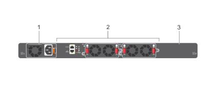
The S4820T power supply unit (PSU) side, shown in the following figure, contains the PSU, fan modules, and console ports.
Figure 1. S4820T PSU-Side View
1. |
PSU 1 |
2. Fan Modules |
3.PSU 2
The S4820T input/output (I/O) side, shown in the following figure, contains the 48 10Gbps RJ-45 autosensing ports, four 40Gbps QSPFP+ ports, a universal serial bus port (USB), and stacking identification light emitting diodes (LEDs).
The S4820T Switch |
7 |
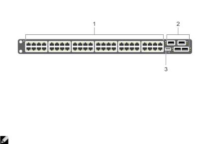
Figure 2. S4820T I/O-Side View
1. |
10GBase-T Ports |
2. QSFP+ Ports |
3.USB Port
NOTE: The RJ-45 ports on the I/O side are labeled 0-47. When you cable these ports, be sure not to interfere with the airflow from the small vent holes above and below the ports.
The S4820T switch runs the Dell Networking operating system (FTOS), providing switching, bridging, and routing functionality for transmitting data, storage, and server traffic.
In a data center network, the S4820T switch provides converged network support and inter-operates with Dell and third-party ToR devices. The switch supports data center bridging (DCB) features and optimizes connectivity between servers and storage devices using Fibre Channel over Ethernet (FCoE) and internet small computer system interface (iSCSI) links.
By providing increased 40GbE bandwidth for device interconnection in a shared network storage environment (with the possibility of splitting 40GbE quad small form-factor pluggable plus (QSFP+) uplinks into four 10GbE SFP+ or RJ-45 connections), the S4820T switch is perfectly positioned to help transition a data center with multiple speed requirements.
Additionally, the S4820T solution is optimized to provide 10Gbps throughput for distances of up to:
•330 feet (100 meters) over Cat6, 6A, and 7 shielded copper cable and Cat6A UTP copper cable
•181.5 feet (55 meters) over Cat6 UTP copper cable
Prerequisites
Detailed installation instructions for the S4820T are provided in Site Preparationsand in Install the Hardware sections. To successfully install the S4820T, ensure that you have the following:
•S4820T chassis (or multiple chassis, if stacking)
•At least one grounded AC or DC power source per chassis
•Cable to connect the AC or DC power source to the chassis (US AC power cables included)
•Mounting brackets for rack installation (included)
•Screws for rack installation and #1 and #2 Phillips screwdrivers (not included)
•Ground cable (not included)
•Ground cable screws (included)
•Copper/fiber cables
8 |
The S4820T Switch |
Other optional components are:
•Additional power supply unit
•Additional fan module
•Additional mounting brackets (if installing in a four-post rack or cabinet)
Features
The S4820T offers the following:
•Forty-eight 1/10Gbps RJ-45 ports
•Four fixed 40Gbps QSFP+ ports for 40Gbps transceivers
•One universal serial bus (USB Type-A) port for additional file storage
•On-board high-performance central processing unit (CPU) system with large memory, P2020/128 MB NOR Flash/2GB DDR III RAM.
•Temperature monitoring (TMP75)
•Software-readable thermal monitor
•Real time clock (RTC) support
•Hot-plugging redundant power supply
•Current monitoring for Power management
•Removable fan that you can manage
•Standard 1U chassis high
Physical Dimensions
The S4820T has the following physical dimensions:
•434 x 460 x 43.5 mm (W x D x H).
•17.09 x 18.11 x 1.71 inches (W x D x H).
Chassis Ports
The following is a list of the standard ports located on each S4820T chassis:
•Serial RS-232 port (RJ-45 type)
•Out of band Ethernet management port (RJ-45 type)
•Forty-eight 1/10Gbps RJ-45 ports
•Four 40Gbps QSFP+ ports for four 40Gbps transceivers
•One universal serial bus port (USB Type-A)
Determine System Status
You can view S4820T status information in several ways, including light emitting diodes (LEDs) and boot menu options.
You can also view status information through the command line interface (CLI) show commands and with simple network management protocol (SNMP) traps. For more information about these options,
The S4820T Switch |
9 |

refer to the FTOS Command Line Reference Guide for the S4820T System and the FTOS Configuration Guide for the S4820T System.
LED Displays
As shown in the following figures, the S4820T includes LED displays on the front and back of the chassis. The tables provide a detailed description of each LED’s meaning.
Figure 3. Port LEDs |
|
|
|
1. |
Diag LED (Green) |
2. |
Temp LED (Red) |
3. |
Stack LED (Blue/Green) |
4. |
Locator LED (Blue) |
5. |
FAN LED (Green/Red) |
6. |
System LED |
7. |
Link LED (Green/Yellow) |
8. |
Activity LED (Blinking Green) |
Table 1 provides a detailed description of each LED for the S4820T system.
Table 2. System LED Displays
Feature |
LED Color/Display |
Comment |
|
|
|
System LED |
• Solid blue –— Normal |
I/O side |
|
Operation |
|
|
• Blinking blue –— Booting |
|
|
• Solid red –— Critical system |
|
|
error |
|
|
• Blinking red –— Non-critical |
|
|
system error (fan fail, power |
|
|
supply fail) |
|
TEMP LED |
• Off –— Normal temperature |
PSU side |
|
• Solid red–Overtemp (Refer to |
|
|
the NOTE that follows this |
|
|
table.) |
|
10 |
The S4820T Switch |
Feature |
LED Color/Display |
Comment |
|
|
|
DIAG LED |
• Off –— Normal operating |
PSU side |
|
• Solid green –— System |
|
|
Booting or Diagnostics |
|
FAN LED |
• Solid green –— Fan powered |
PSU side |
|
and running at the expected |
|
|
rpm |
|
|
• Solid red –— Fan failed |
|
STACK LED |
• Solid blue –— Switch in |
PSU side |
|
stacking master mode |
|
|
• Solid green –— Switch in |
|
|
stacking slave mode |
|
|
• Off –— Switch in stand-alone |
|
|
mode |
|
LOCATOR LED |
• Blinking blue –— Locator |
PSU side |
|
function is enabled |
|
|
• Solid blue –— Locator |
|
|
function is disabled |
|
NOTE: The system temperature threshold is 75°C. When one of the thermal sensors exceeds this |
||
temperature, the TEMP LED turns RED. |
|
|
Table 3. 10GBT Ethernet Port LEDs |
|
|
|
|
|
Feature |
LED Color/Display |
|
|
|
|
Link LED |
• Off –— No Link |
|
|
• Solid green –— Link on 10Gbps speed |
|
|
• Solid Amber –— Link on 100M or 1Gbps speeds |
|
Activity LED |
• Off –— No Link |
|
|
• Blinking green –— Transmit/Receive is active |
|
Table 4. QSFP+ Port LEDs |
|
|
|
|
|
Feature |
LED Color/Display |
|
|
|
|
Link LED |
• Off –— No Link |
|
|
• Solid green –— Link on 40Gbps speed |
|
|
• Solid amber –— Link on other speeds |
|
Activity LED |
• Off –— No Link |
|
|
• Blinking green –— Transmit/Receive is active |
|
Table 5. OOB Ethernet Port LEDs |
|
|
|
|
|
Feature |
LED Color/Display |
|
|
|
|
Link LED |
• Off –— No Link |
|
|
• Solid green –— Link on 1Gbps speed |
|
The S4820T Switch |
11 |

Feature |
LED Color/Display |
|
|
|
|
|
• Solid amber –— Link on 100M or 10M speeds |
|
Activity LED |
• |
Off –— No Link |
|
• |
Blinking green –— Transmit/Receive is active |
Orderable S4820T Components
You can order the S4820T system in several different configurations. You can also order optional modules and optics separately.
You can order the following supported hardware components.
•S4820T AC Normal Airflow: 48 port 10G RJ-45 ports with 4 QSFP+ 40G ports, 1 AC power supply and 2 fan subsystems (airflow from I/O side to power supply side)
•S4820T AC Reverse Airflow: 48 port 10G RJ-45 ports with 4 QSFP+ 40G ports, 1 AC power supply and 2 fan subsystems (airflow from power supply side to I/O side)
•S4820T AC Normal Airflow: 48 port 10G RJ-45 ports with 4 QSFP+ 40G ports, 1 DC power supply and 2 fan subsystems (airflow from I/O side to power supply side)
•S4820T AC Reverse Airflow: 48 port 10G RJ-45 ports with 4 QSFP+ 40G ports, 1 DC power supply and 2 fan subsystems (airflow from power supply side to I/O side)
•S4820T Series — Fan with airflow from the I/O side to the PSU side
•S4820T Series — Fan with airflow from the PSU side to the I/O side
•S4820T Series — AC Power supply with airflow from the I/O side to the PSU side
•S4820T Series — AC Power supply with airflow from the PSU side to the I/O side
•S4820T Series — DC Power supply with airflow from the I/O side to the PSU side
•S4820T Series — DC Power supply with airflow from the PSU side to the I/O side
12 |
The S4820T Switch |

3
Site Preparations
The S4820T is suitable for installation as part of a common bond network (CBN). You can install the system in:
•network telecommunication facilities
•data centers
•other locations where the National Electric Code (NEC) applies
For S4820T specifications, refer to Technical Specifications.
NOTE: Install the S4820T system into a rack or cabinet before installing any optional components.
Site Selection
Install Dell Networking equipment in restricted access areas. A restricted access area is one in which access can only be gained by service personnel by using a special tool, lock, key or other means of security and access is controlled by the authority responsible for the location.
Ensure that the area where you install your S4820T system meets the following safety requirements:
•Near an adequate power source. Connect the system to the appropriate branch circuit protection as defined by your local electrical codes.
•Environmental temperature between 32° to 104°F (from 0° to 40°C).
•Relative humidity that does not exceed 85% noncondensing.
•In a dry, clean, well-ventilated and temperature-controlled room, away from heat sources such as hot air vents or direct sunlight.
•Away from sources of severe electromagnetic noise.
•Positioned in a rack or cabinet, or on a desktop with adequate space in the front, rear, and sides of the S4820T for proper ventilation and access.
Cabinet Placement
Install the S4820T only in indoor cabinets designed for use in a controlled environment.
Do not install the S4820T in outside plant cabinets. For cabinet placement requirements, refer to Site Selection.
The cabinet must be a minimum cabinet size. Airflow must be according to the Electronic Industries Alliance (EIA) standard.
Site Preparations |
13 |

Rack Mounting
When you prepare your equipment rack, ensure that the rack is earth ground.
Ground the equipment rack to the same ground point the power service in your area uses. The ground path must be permanent.
Grounding
Use the S4820T in a common bond network (CBN).
Connect the grounding cables as described in Attaching the Ground Cable.
Fans and Airflow
The S4820T fans support two airflow options.
Be sure to order the fans suitable to support your site’s ventilation. Use a single type of airflow fan in your system. Do not mix reverse and normal airflows in a single S4820T chassis.
•Normal — airflow is from the I/O panel to the power supply
•Reversed — airflow is from the power supply to the I/O panel
For proper ventilation, position the S4820T in an equipment rack (or cabinet) with a minimum of five inches (12.7cm) of clearance around the exhaust vents. When you install two S4820T systems near each other, position the two chassis at least five inches (12.7cm) apart to permit proper airflow. The acceptable ambient temperature ranges are listed in Technical Specifications.
The fan speed increases when the internal temperature reaches 72°C and decreases to normal speed when the temperature falls to 58°C. The switch never intentionally turns off the fans.
To see the log messages, use the show logging command. For more information, refer to the System Logs chapters of the FTOS Command Line Reference Guide for the S4820T System and FTOS Configuration Guide for the S4820T System.
NOTE: Power Supplies and Fan Modules are field replaceable units. Dell Networking does not support a mix of power supply types (such as, AC and DC) in the same switch. If a power supply is added or replaced, it MUST match the existing type of power supply (such as, AC and AC or DC and DC).
Power
To connect the chassis to the applicable power source, use the appropriate power cord with the S4820T system.
A country/region-specific AC or DC power cord is included with the system.
When installing AC systems, follow the requirements of the National Electrical Code, ANSI/NFPA 70 where applicable.
The system is powered-up as soon as the power cord is connected between the system and the power source.
14 |
Site Preparations |

CAUTION: Always disconnect the power cable before you service the power supply slots.
CAUTION: Use the power supply cord as the main disconnect device on the AC system. Ensure that the socket-outlet is located/installed near the equipment and is easily accessible.
Storing Components
If you do not install your S4820T and components immediately, Dell Networking recommends properly storing the system and all optional components until you are ready to install them.
WARNING: Electrostatic discharge (ESD) damage can occur when components are mishandled. Always wear an ESD-preventive wrist or heel ground strap when handling the S4820T and its accessories. After you remove the original packaging, place the S4820T and its components on an antistatic surface.
Follow these storage guidelines:
•Storage temperature must remain constant ranging from -4° to 158°F (-20°C to 70°C).
•Store on a dry surface or floor, away from direct sunlight, heat, and air conditioning ducts.
•Store in a dust-free environment.
Site Preparations |
15 |
16

4
Install the Hardware
Always handle the S4820T and its components with care. Avoid dropping the system or its field replaceable units (FRUs). Dell Networking recommends completing the installation procedures in the order presented in this document.
Before installing the switch, verify that you meet these guidelines:
•You have enough clearance to the front of the switch so you can read the light emitting diodes (LEDs).
•The AC/DC power cord reaches from the power outlet to the Utility-panel connector.
•The switch is rack-mounted before you power it up.
•Cabling is away from sources of electrical noise, such as radios, power lines, and fluorescent lighting. Ensure the cabling is safely away from other devices that might damage the cables. If needed, allow one rack unit (RU) space between devices to provide room for cabling.
•Airflow around the switch and through the vents is unrestricted.
•Temperature around the unit does not exceed 104°F (40°C). If the switch is in a closed or multirack assembly, the temperature might be higher than normal room temperature.
•Humidity around the switch does not exceed 85 percent.
•Altitude at the installation site is below 6600 feet.
•You install the switch in an environment as free as possible from dust and foreign conductive material (such as metal flakes from construction activities). Cooling mechanisms, such as fans and blowers in the switch, can draw dust and other particles causing contaminant buildup inside the chassis, which can result in system malfunction.
Unpacking the Switch
The S4820T and its accessories are shipped in multiple boxes.
Before unpacking the switch, inspect the container and immediately report any evidence of damage. Verify that you have received your ordered items. For example, if you order one S4820T switch, the following items are included.
WARNING: If any item is missing or damaged, contact your Dell Networking representative or reseller for instructions.
WARNING: Electrostatic discharge (ESD) damage can occur if components are mishandled. Always wear an ESD-preventive wrist or heel ground strap when handling the S4820T and its components.
•One S4820T switch
•One power supply (either AC or DC)
•Two sets of rail kits (no tools required)
•One RJ-45 to DB-9 female cable
•One AC or DC power cord for AC or DC units (country/region specific)
•Getting Started Guide
•Safety and Regulatory Information
Install the Hardware |
17 |

•Warranty and Support Information
•Software License Agreement
1.Place the container on a clean, flat surface and cut all straps securing the container.
2.Open the container or remove the container top.
3.Carefully remove all components from the container and place it on a secure and clean surface.
4.Remove all packing material.
5.Inspect the switch and accessories for damage.
Install the Chassis
To install the S4820T system, Dell Networking recommends completing the installation procedures in the order presented in this document.
You can install the S4820T switch on a rack shelf or mount it directly into a 19–inch wide, EIA-310-E- compliant rack (four-post, two-post, or threaded methods). Dell Networking provides the Dell ReadyRails™ system for 1U front-rack and two-post installations. The ReadyRails system includes two separately packaged rail assemblies and two rails that are shipped attached to the sides of the switch.
NOTE: Always handle the system and its components with care. Avoid dropping the S4820T chassis or its field replaceable units.
NOTE: For proper ventilation, position the S4820T chassis in an equipment rack (or cabinet) with a minimum of 5 inches (12.7 cm) of clearance around exhaust vents. The acceptable ambient temperature ranges are listed in the Technical Specifications section under Environmental Parameters.
NOTE: The illustrations in this document are not intended to represent a specific switch.
CAUTION: Always wear an electrostatic discharge (ESD)-preventive wrist or heel ground strap when handling the S4820T and its components. As with all electrical devices of this type, take necessary safety precautions to prevent injury when installing this system. ESD damage can occur if components are mishandled.
WARNING: This is a condensed reference. Read the safety instructions in your Safety, Environmental, and Regulatory information booklet before you begin.
Rack Mounting Safety Considerations
You can install the S4820T switch on a rack shelf or mount it directly into a 19" wide, EIA-310-E- compliant rack.
•Rack loading — Overloading or uneven loading of racks may result in shelf or rack failure, which may damage the equipment and cause personal injury. Stabilize the racks in a permanent location before loading begins. Mount the components beginning at the bottom of the rack, then work to the top. Do not exceed your rack load rating.
•Power considerations — Connect only to the power source specified on the unit. When you install multiple electrical components in a rack, ensure that the total component power ratings do not exceed the circuit capabilities. Overloaded power sources and extension cords present fire and shock hazards.
•Elevated ambient temperature — If you install the equipment in a closed rack assembly, the operating temperature of the rack environment may be greater than the room ambient temperature. Use care not to exceed the 40°C maximum ambient temperature of the switch.
•Reduced air flow — Install the equipment in the rack so that you do not compromise the amount of airflow required for safe operation of the equipment.
18 |
Install the Hardware |
Loading...