


 Loading...
Dell EMC PowerEdge M640 for VRTX enclosure
Installation and Service Manual
Regulatory Model: HHB Series
Regulatory Type: HHB006
July 2020
Rev. A07

Notes, cautions, and warnings

 NOTE: A NOTE indicates important information that helps you make better use of your product.
 CAUTION: A CAUTION indicates either potential damage to hardware or loss of data and tells you how to avoid the problem.
 WARNING: A WARNING indicates a potential for property damage, personal injury, or death.
© 2017 -2020 Dell Inc. or its subsidiaries. All rights reserved. Dell, EMC, and other trademarks are trademarks of Dell Inc. or its subsidiaries. Other trademarks may be trademarks of their respective owners.

Contents
Chapter 1: Dell EMC PowerEdge M640 overview................................................................................ |
7 |
Front view of the system...................................................................................................................................................... |
7 |
Health status indicator.................................................................................................................................................... |
8 |
Hard drive indicator codes.............................................................................................................................................. |
8 |
iDRAC Direct LED indicator codes................................................................................................................................ |
9 |
Locating the Service Tag of your system..................................................................................................................... |
9 |
System information label..................................................................................................................................................... |
10 |
Chapter 2: Documentation resources............................................................................................... |
11 |
Chapter 3: Technical specifications................................................................................................. |
13 |
System dimensions............................................................................................................................................................... |
13 |
System weight...................................................................................................................................................................... |
13 |
Processor specifications...................................................................................................................................................... |
14 |
Supported operating systems............................................................................................................................................. |
14 |
System battery specifications............................................................................................................................................ |
14 |
Memory specifications......................................................................................................................................................... |
14 |
Mezzanine card specifications........................................................................................................................................... |
14 |
Storage controller specifications........................................................................................................................................ |
14 |
Drive specifications.............................................................................................................................................................. |
14 |
Hard drives...................................................................................................................................................................... |
15 |
Ports and connectors specifications................................................................................................................................. |
15 |
USB ports........................................................................................................................................................................ |
15 |
Internal Dual SD Module ............................................................................................................................................... |
15 |
Micro SD vFlash connector........................................................................................................................................... |
15 |
Video specifications ............................................................................................................................................................ |
15 |
Environmental specifications.............................................................................................................................................. |
15 |
Particulate and gaseous contamination specifications ............................................................................................. |
16 |
Standard operating temperature.................................................................................................................................. |
17 |
Expanded operating temperature................................................................................................................................. |
17 |
Expanded operating temperature restrictions............................................................................................................ |
18 |
Thermal Restriction matrix............................................................................................................................................ |
18 |
Chapter 4: Initial system setup and configuration............................................................................ |
20 |
Setting up your system....................................................................................................................................................... |
20 |
iDRAC configuration............................................................................................................................................................ |
20 |
Options to set up iDRAC IP address........................................................................................................................... |
20 |
Log in to iDRAC.............................................................................................................................................................. |
21 |
Options to install the operating system............................................................................................................................. |
21 |
Methods to download firmware and drivers............................................................................................................... |
21 |
Downloading drivers and firmware.............................................................................................................................. |
22 |
Chapter 5: Pre-operating system management applications............................................................. |
23 |
Options to manage the pre-operating system applications........................................................................................... |
23 |
Contents 3
System Setup....................................................................................................................................................................... |
23 |
Viewing System Setup.................................................................................................................................................. |
23 |
System Setup details..................................................................................................................................................... |
24 |
System BIOS.................................................................................................................................................................. |
24 |
iDRAC Settings utility.................................................................................................................................................... |
43 |
Device Settings.............................................................................................................................................................. |
43 |
Dell Lifecycle Controller...................................................................................................................................................... |
43 |
Embedded system management................................................................................................................................. |
43 |
Boot Manager...................................................................................................................................................................... |
43 |
Viewing Boot Manager.................................................................................................................................................. |
43 |
Boot Manager main menu............................................................................................................................................ |
44 |
One-shot UEFI boot menu........................................................................................................................................... |
44 |
System Utilities.............................................................................................................................................................. |
44 |
PXE boot.............................................................................................................................................................................. |
44 |
Chapter 6: Installing and removing system components................................................................... |
45 |
Safety instructions.............................................................................................................................................................. |
45 |
Before working inside your system................................................................................................................................... |
45 |
After working inside your system...................................................................................................................................... |
46 |
Recommended tools........................................................................................................................................................... |
46 |
Removing the system from the enclosure....................................................................................................................... |
46 |
Installing the system into the enclosure........................................................................................................................... |
48 |
Inside the system................................................................................................................................................................. |
49 |
System cover....................................................................................................................................................................... |
50 |
Removing the system cover........................................................................................................................................ |
50 |
Installing the system cover............................................................................................................................................ |
51 |
Air shroud............................................................................................................................................................................. |
53 |
Removing the air shroud............................................................................................................................................... |
53 |
Installing the air shroud................................................................................................................................................. |
53 |
Drives.................................................................................................................................................................................... |
54 |
Removing a drive blank................................................................................................................................................. |
54 |
Installing a drive blank................................................................................................................................................... |
55 |
Removing a drive carrier............................................................................................................................................... |
55 |
Installing a drive carrier................................................................................................................................................. |
56 |
Removing a drive from a drive carrier......................................................................................................................... |
57 |
Installing a drive into drive carrier................................................................................................................................ |
58 |
Removing the drive cage.............................................................................................................................................. |
59 |
Installing the drive cage................................................................................................................................................ |
60 |
Drive backplane.................................................................................................................................................................... |
61 |
Removing the drive backplane...................................................................................................................................... |
61 |
Installing the drive backplane....................................................................................................................................... |
63 |
System memory .................................................................................................................................................................. |
65 |
System memory guidelines........................................................................................................................................... |
65 |
General memory module installation guidelines......................................................................................................... |
66 |
Mode-specific guidelines.............................................................................................................................................. |
66 |
Removing a memory module........................................................................................................................................ |
68 |
Installing a memory module.......................................................................................................................................... |
69 |
Processors and heat sinks.................................................................................................................................................. |
70 |
Removing a processor and heat sink module............................................................................................................. |
70 |
Removing the processor from the processor and heat sink module....................................................................... |
71 |
4 Contents
Installing the processor into a processor and heat sink module.............................................................................. |
73 |
Installing a processor and heat sink module............................................................................................................... |
75 |
M.2 SSD module.................................................................................................................................................................. |
76 |
Removing the M.2 SSD module................................................................................................................................... |
76 |
Installing the M.2 SSD module..................................................................................................................................... |
77 |
Network Daughter Card..................................................................................................................................................... |
78 |
Removing the Network Daughter Card...................................................................................................................... |
78 |
Installing the Network Daughter Card........................................................................................................................ |
79 |
PCIe mezzanine card.......................................................................................................................................................... |
80 |
PCIe mezzanine card installation guidelines............................................................................................................... |
80 |
Removing the PCIe mezzanine card........................................................................................................................... |
80 |
Installing the PCIe mezzanine card.............................................................................................................................. |
81 |
Storage controller card ...................................................................................................................................................... |
82 |
Removing the storage controller card........................................................................................................................ |
82 |
Installing the storage controller card........................................................................................................................... |
83 |
System battery.................................................................................................................................................................... |
84 |
Replacing the NVRAM backup battery - Option A................................................................................................... |
84 |
Replacing the NVRAM backup battery - Option B................................................................................................... |
86 |
Optional internal USB memory key.................................................................................................................................... |
87 |
Replacing optional internal USB memory key............................................................................................................. |
87 |
Optional MicroSD or vFlash card....................................................................................................................................... |
88 |
Removing the internal micro SD card......................................................................................................................... |
88 |
Installing an internal micro SD card............................................................................................................................. |
88 |
IDSDM................................................................................................................................................................................... |
89 |
Removing the optional internal dual SD module ....................................................................................................... |
89 |
Installing the optional internal dual SD module.......................................................................................................... |
90 |
System board........................................................................................................................................................................ |
91 |
Removing the system board......................................................................................................................................... |
91 |
Installing the system board........................................................................................................................................... |
93 |
Trusted Platform Module................................................................................................................................................... |
96 |
Upgrading the Trusted Platform Module................................................................................................................... |
96 |
Initializing TPM for BitLocker users............................................................................................................................. |
97 |
Initializing the TPM 1.2 for TXT users......................................................................................................................... |
97 |
Initializing the TPM 2.0 for TXT users........................................................................................................................ |
97 |
rSPI card............................................................................................................................................................................... |
98 |
Removing the rSPI card................................................................................................................................................ |
98 |
Installing the rSPI card.................................................................................................................................................. |
99 |
Chapter 7: System diagnostics..................................................................................................... |
100 |
Dell Embedded System Diagnostics................................................................................................................................ |
100 |
Running the Embedded System Diagnostics from Boot Manager........................................................................ |
100 |
Running the Embedded System Diagnostics from the Dell Lifecycle Controller................................................. |
100 |
System diagnostic controls.......................................................................................................................................... |
101 |
Chapter 8: Jumpers and connectors.............................................................................................. |
102 |
System board jumpers and connectors.......................................................................................................................... |
102 |
System board jumper settings.......................................................................................................................................... |
103 |
Disabling a forgotten password........................................................................................................................................ |
103 |
Contents 5
Chapter 9: Getting help................................................................................................................ |
105 |
Contacting Dell EMC......................................................................................................................................................... |
105 |
Documentation feedback.................................................................................................................................................. |
105 |
Accessing system information by using QRL................................................................................................................. |
105 |
Quick Resource Locator for PowerEdge M640 system......................................................................................... |
106 |
Receiving automated support with SupportAssist ....................................................................................................... |
106 |
Recycling or End-of-Life service information................................................................................................................. |
106 |
6 Contents

1
Dell EMC PowerEdge M640 overview
The Dell EMC PowerEdge M640 is a half-height server module supported on the PowerEdge VRTX enclosure and supports up to:
•Two Intel Xeon scalable processors
•Two 2.5-inch hard drives/SSDs
•16 DIMMs
NOTE: All instances of SAS, SATA hard drives and SSDs are referred to as drives in this document, unless specified otherwise.
Topics:
•Front view of the system
•System information label
Front view of the system
The front view displays the features available on the front of the system.
Figure 1. Front view of the system
Table 1. Features available on the front of the system
Item |
Ports, panels, and |
Icon |
Description |
|
components |
|
|
|
|
|
|
1 |
Hard drives/SSDs |
N/A |
2.5-inch hard drive/SSDs are supported. For more information, see |
|
|
|
theTechnical specificationssection. |
2USB 3.0 port
3iDRAC Direct port
Enables you to connect USB devices to the system.
The iDRAC Direct port is micro USB 2.0-compliant. This port enables you to access the iDRAC Direct features. For more information, see the Integrated Dell Remote Access Controller User's Guide at www.dell.com/poweredgemanuals.
4 |
iDRAC Direct LED |
N/A |
The iDRAC Direct LED indicator lights up to indicate that the iDRAC |
|
indicator |
|
Direct port is actively connected to a device. For more information, |
|
|
|
see the iDRAC Direct LED indicator codessection. |
5 |
Status indicator |
|
Provides information about the status of the system. For more |
|
|
|
information, see the Health status indicator section. |
Dell EMC PowerEdge M640 overview |
7 |

Table 1. Features available on the front of the system (continued)
Item |
Ports, panels, and |
Icon |
Description |
||
|
components |
|
|
|
|
|
|
|
|
||
6 |
Power button |
|
Indicates if the system is turned on or off. Press the power button to |
||
|
|
|
manually turn on or off the system. |
||
|
|
|
|
|
NOTE: Press the power button to gracefully shut down an |
|
|
|
|
|
|
|
|
|
|
||
|
|
|
|
|
ACPI-compliant operating system. |
7 |
System handle release |
N/A |
Enables you to unlock the system from the enclosure. |
||
|
button |
|
|
|
|
|
|
|
|
|
|
Health status indicator
The Health status indicator indicates the health condition of the system.
Table 2. Health status indicator codes
Icon |
Health-status indicator |
Condition |
|
pattern |
|
|
|
|
|
|
|
|
Solid blue |
No errors are present in the system. System is in good health. |
|
|
|
|
Blinking blue |
Identify mode is enabled (regardless of system errors)—system is in |
|
|
the process of identifying the system. |
|
|
|
|
Solid amber |
System is in failsafe mode—system is not ready or available and |
|
|
cannot be turned on. |
|
|
|
|
Flashes amber |
Errors present in the system. |
|
|
|
Hard drive indicator codes
Each drive carrier has an activity LED indicator and a status LED indicator. The indicators provide information about the current status of the drive. The activity LED indicator indicates whether the drive is currently in use or not. The status LED indicator indicates the power condition of the drive.
Figure 2. Drive indicators on the drive and the mid drive tray backplane
1.Drive activity LED indicator
2.Drive status LED indicator
3.Drive capacity label
If the drive is in the Advanced Host Controller Interface (AHCI) mode, the status LED indicator does not turn on.
8 Dell EMC PowerEdge M640 overview
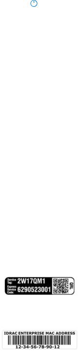
Table 3. Drive indicator codes
Drive status indicator code |
Condition |
||
|
|
||
Flashes green twice per second |
Identifying drive or preparing for removal. |
||
Off |
Drive ready for removal. |
||
|
|
|
NOTE: The drive status indicator remains off until all drives |
|
|
||
|
|
|
are initialized after the system is turned on. Drives are not |
|
|
|
ready for removal during this time. |
Flashes green, amber, and then turns off |
Predicted drive failure. |
||
Flashes amber four times per second |
Drive failed. |
||
Flashes green slowly |
Drive rebuilding. |
||
Solid green |
Drive online. |
||
Flashes green for three seconds, amber for three seconds, |
Rebuild stopped. |
||
and then turns off after six seconds |
|
|
|
|
|
|
|
iDRAC Direct LED indicator codes
The iDRAC Direct LED indicator lights up to indicate that the port is connected and is being used as a part of the iDRAC subsystem.
You can configure iDRAC Direct by using a USB to micro USB (type AB) cable, which you can connect to your laptop or tablet. The following table describes iDRAC Direct activity when the iDRAC Direct port is active:
Table 4. iDRAC Direct LED indicator codes
iDRAC Direct LED |
Condition |
indicator code |
|
|
Indicates that the laptop or tablet is connected. |
Solid green for two seconds |
|
Flashing green (on for two |
Indicates that the laptop or tablet connected is recognized. |
seconds and off for two |
|
seconds) |
|
Turns off |
Indicates that the laptop or tablet is unplugged. |
Locating the Service Tag of your system
You can identify your system using the unique Express Service Code and Service Tag. The service tag information is available on a sticker on the chassis of the system. This information is used by Dell EMC personnel to route support calls to the appropriate personnel.
The following image displays a sample service tag, which is available as a sticker on the hard drive cage.
Figure 3. Sample Service Tag
The following image displays a sample iDRAC MAC address label, which is available as a sticker at the bottom of the system.
Figure 4. Sample iDRAC MAC address
Dell EMC PowerEdge M640 overview |
9 |

System information label
Figure 5. System information label
10 Dell EMC PowerEdge M640 overview
2
Documentation resources
This section provides information about the documentation resources for your system.
To view the document that is listed in the documentation resources table:
•From the Dell EMC support site:
1.Click the documentation link that is provided in the Location column in the table.
2.Click the required product or product version.

 NOTE: To locate the product name and model, see the front of your system.
3. On the Product Support page, click Manuals & documents.
•Using search engines:
○ Type the name and version of the document in the search box.
Table 5. Additional documentation resources for your system
Task |
Document |
Location |
|
|
|
|
|
|
Setting up your system |
For information about installing the system into |
www.dell.com/poweredgemanuals |
|
the enclosure, see the Getting Started Guide |
|
|
document that is shipped with your system. |
|
|
|
|
Configuring your system |
For information about the iDRAC features, |
www.dell.com/poweredgemanuals |
|
configuring and logging in to iDRAC, and managing |
|
|
your system remotely, see the Integrated Dell |
|
|
Remote Access Controller User's Guide. |
|
|
For information about understanding Remote |
|
|
Access Controller Admin (RACADM) |
|
|
subcommands and supported RACADM |
|
|
interfaces, see the RACADM CLI Guide for iDRAC. |
|
|
For information about Redfish and its protocol, |
|
|
supported schema, and Redfish Eventing are |
|
|
implemented in iDRAC, see the Redfish API Guide. |
|
|
For information about iDRAC property database |
|
|
group and object descriptions, see the Attribute |
|
|
Registry Guide. |
|
|
|
|
|
For information about earlier versions of the |
www.dell.com/idracmanuals |
|
iDRAC documents, see the iDRAC documentation. |
|
|
To identify the version of iDRAC available on your |
|
|
system, on the iDRAC web interface, click ? > |
|
|
About. |
|
|
|
|
|
For information about installing the operating |
www.dell.com/operatingsystemmanuals |
|
system, see the operating system documentation. |
|
|
|
|
|
For information about updating drivers and |
www.dell.com/support/drivers |
|
firmware, see the Methods to download firmware |
|
|
and drivers section in this document. |
|
|
|
|
Managing your system |
For information about systems management |
www.dell.com/poweredgemanuals |
|
software offered by Dell, see the Dell |
|
|
OpenManage Systems Management Overview |
|
|
Guide. |
|
|
|
|
Documentation resources |
11 |
Table 5. Additional documentation resources for your system (continued)
Task |
Document |
Location |
|
|
|
|
|
|
|
For information about setting up, using, and |
www.dell.com/openmanagemanuals > |
|
troubleshooting OpenManage, see the Dell |
OpenManage Server Administrator |
|
OpenManage Server Administrator User’s Guide. |
|
|
|
|
|
For information about installing, using, and |
www.dell.com/openmanagemanuals > |
|
troubleshooting Dell OpenManage Essentials, see |
OpenManage Essentials |
|
the Dell OpenManage Essentials User’s Guide. |
|
|
|
|
|
For information about installing, using, and |
www.dell.com/openmanagemanuals > |
|
troubleshooting Dell OpenManage Enterprise, see |
OpenManage Enterprise |
|
the Dell OpenManage Enterprise User’s Guide. |
|
|
|
|
|
For information about installing and using Dell |
www.dell.com/serviceabilitytools |
|
SupportAssist, see the Dell EMC SupportAssist |
|
|
Enterprise User’s Guide. |
|
|
|
|
|
For information about partner programs enterprise |
www.dell.com/openmanagemanuals |
|
systems management, see the OpenManage |
|
|
Connections Enterprise Systems Management |
|
|
documents. |
|
|
|
|
|
For information about viewing inventory, |
www.dell.com/openmanagemanuals > Chassis |
|
performing configuration, and monitoring tasks, |
Management Controllers |
|
remotely turning on or off servers, and enabling |
|
|
alerts for events on servers and components using |
|
|
the Dell Chassis Management Controller (CMC), |
|
|
see the CMC User’s Guide. |
|
|
|
|
Working with the Dell |
For information about understanding the features |
www.dell.com/storagecontrollermanuals |
PowerEdge RAID controllers |
of the Dell PowerEdge RAID controllers (PERC), |
|
|
Software RAID controllers, or BOSS card and |
|
|
deploying the cards, see the Storage controller |
|
|
documentation. |
|
|
|
|
Understanding event and error |
For information about the event and error |
www.dell.com/qrl |
messages |
messages that are generated by the system |
|
|
firmware and agents that monitor system |
|
|
components, see the Error Code Lookup. |
|
|
|
|
Troubleshooting your system |
For information about identifying and |
www.dell.com/poweredgemanuals |
|
troubleshooting the PowerEdge server issues, see |
|
|
the Server Troubleshooting Guide. |
|
|
|
|
12 Documentation resources
3
Technical specifications
Topics:
•System dimensions
•System weight
•Processor specifications
•Supported operating systems
•System battery specifications
•Memory specifications
•Mezzanine card specifications
•Storage controller specifications
•Drive specifications
•Ports and connectors specifications
•Video specifications
•Environmental specifications
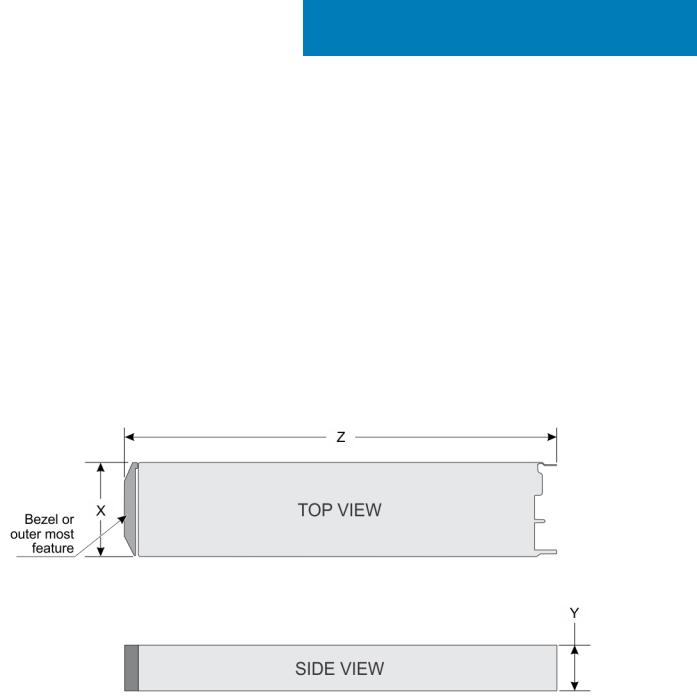
System dimensions
Figure 6. System dimensions
Table 6. System dimensions of the Dell EMC PowerEdge M640 system
System |
X |
Y |
Z (handle closed) |
|
|
|
|
|
|
|
|
Dell EMC PowerEdge M640 |
197.92 mm (7.79 inches) |
50.35 mm (1.98 inches) |
544.32 mm (21.43 inches) |
|
|
|
|
System weight
Table 7. System weight
System |
Maximum weight |
|
|
|
|
Dell EMC PowerEdge M640 |
6.4 kg (14.11 lb) |
|
|
Technical specifications |
13 |
Processor specifications
The PowerEdge M640 system supports up to two Intel Xeon Processor Scalable processors up to 28 cores per processor.
Supported operating systems
The PowerEdge FC640 supports the follow operating systems:
•RedHat Enterprise Linux Server
•SUSE Linux Enterprise Server
•Microsoft Windows Server
•VMware
•Citrix Xen Server
•Canonical Ubuntu LTS
For more information, go to www.dell.com/ossupport
System battery specifications
The PowerEdge M640 system supports CR 2032 3.0-V lithium coin cell system battery.
Memory specifications
Table 8. Memory specifications
Memory module |
DIMM |
|
DIMM |
Single processor |
Dual processors |
||
DIMM rank |
|
|
|
|
|||
|
|
|
|
||||
sockets |
type |
capacity |
Minimum |
Maximum |
Minimum RAM |
Maximum RAM |
|
|
|
|
|
RAM |
RAM |
|
|
|
|
|
|
|
|
|
|
Sixteen 288-pins |
LRDIMM |
Octa rank |
128 GB |
128 GB |
1024 GB |
256 GB |
2048 GB |
|
|
|
|
|
|
|
|
|
|
Quad rank |
64 GB |
64 GB |
512 GB |
128 GB |
1024 GB |
|
|
|
|
|
|
|
|
|
|
Single rank |
8 GB |
8 GB |
64 GB |
16 GB |
128 GB |
|
|
|
|
|
|
|
|
|
RDIMM |
Dual rank |
16 GB |
16 GB |
128 GB |
32 GB |
256 GB |
|
|
|
|
|
|
|
|
|
Dual rank |
32 GB |
32 GB |
256 GB |
64 GB |
512 GB |
|
|
|
||||||
|
|
|
|
|
|
|
|
|
|
Dual rank |
64 GB |
64 GB |
512 GB |
128 GB |
1024 GB |
|
|
|
|
|
|
|
|
Mezzanine card specifications
The PowerEdge M640 system supports two PCIe x8 Gen 3 slots mezzanine card supporting dual port 10 Gb Ethernet, quad port 1 Gb, FC8 Fibre Channel, FC16 Fibre Channel, or Infiniband mezzanine cards.
Storage controller specifications
The PowerEdge M640p system supports :
•Internal controllers:Software RAID S140, PowerEdge RAID controller(PERC)9 H330, H730P
•Boot Optimized Storage Subsystem(BOSS): HWRAID 2 x M.2 SSDs 120GB, 240 GB
•Internal Dual SD Module optional
Drive specifications
14 Technical specifications

Hard drives
The PowerEdge M640 system supports up to two 2.5-inch, hot-swappable SAS/SATA hard drives, SSDs, or PCIe NVMe drives.
Ports and connectors specifications
USB ports
The PowerEdge M640 system supports:
•One USB 3.0-compliant port on the front of the system
•One micro USB/iDRAC direct USB 2.0-compliant port on the front of the system
•One USB 3.0-compliant internal port
NOTE: The micro USB 2.0-compliant port on the front of the system can only be used as an iDRAC Direct or a management port.
Internal Dual SD Module
The PowerEdge M640 system supports two internal micro SD cards dedicated for the hypervisor. This card offers the following features:
•Dual card operation — maintains a mirrored configuration by using micro SD cards in both slots and provides redundancy.
•Single card operation — single card operation is supported, but without redundancy.
NOTE: One IDSDM card slot is dedicated for redundancy. It is recommended to use Dell branded micro SD cards associated with the IDSDM/micro SD vFlash configured systems.
Micro SD vFlash connector
The Dell EMC PowerEdge M640 system supports one dedicated micro SD card for vFlash support.
Video specifications
Table 9. Video specifications
Features |
Specifications |
|
|
|
|
Video type |
Matrox G200 graphics controller integrated with iDRAC |
|
|
Video memory |
4 GB DDR4 shared with iDRAC application memory |
|
|
|
|
Environmental specifications
NOTE: For additional information about environmental certifications, please refer to the Product Environmental Datasheet located with the Manuals & Documents on www.dell.com/poweredgemanuals
Table 10. Temperature specifications
Temperature |
Specifications |
|
|
|
|
Storage |
–40°C to 65°C (–40°F to 149°F) |
|
|
Continuous operation (for altitude less than 950 m or 3117 |
10°C to 35°C (50°F to 95°F) with no direct sunlight on the equipment. |
ft) |
|
|
|
Maximum temperature gradient (operating and storage) |
20°C/h (68°F/h) |
|
|
Technical specifications |
15 |

Table 11. Relative humidity specifications
Relative humidity |
Specifications |
|
|
|
|
Storage |
5% to 95% RH with 33°C (91°F) maximum dew point. Atmosphere must |
|
be non-condensing at all times. |
|
|
Operating |
10% to 80% relative humidity with 26°C (78.8°F) maximum dew point. |
|
|
Table 12. Maximum vibration specifications
Maximum vibration |
Specifications |
|
|
|
|
Operating |
0.26 Grms at 5 Hz to 350 Hz (all operation orientations). |
Storage |
1.87 Grms at 10 Hz to 500 Hz for 15 min (all six sides tested). |
Table 13. Maximum shock specifications
Maximum shock |
Specifications |
|
|
|
|
Operating |
Six consecutively executed shock pulses in the positive and negative x, y, |
|
and z axes of 6 G for up to 11 ms. |
|
|
Storage |
Six consecutively executed shock pulses in the positive and negative x, y, |
|
and z axes (one pulse on each side of the system) of 71 G for up to 2 ms. |
|
|
Table 14. Maximum altitude specifications
Maximum altitude |
Specifications |
|
|
|
|
Operating |
3048 m (10,000 ft) |
|
|
Storage |
12,000 m (39,370 ft) |
|
|
Table 15. Operating temperature de-rating specifications
Operating temperature de-rating |
Specifications |
|
|
|
|
Up to 35°C (95°F) |
Maximum temperature is reduced by 1°C/300 m (1°F/547 ft) above 950 m |
|
(3,117 ft). |
|
|
35°C to 40°C (95°F to 104°F) |
Maximum temperature is reduced by 1°C/175 m (1°F/319 ft) above 950 m |
|
(3,117 ft). |
|
|
40°C to 45°C (104°F to 113°F) |
Maximum temperature is reduced by 1°C/125 m (1°F/228 ft) above 950 m |
|
(3,117 ft). |
|
|
Particulate and gaseous contamination specifications
The following table defines the limitations that help avoid any equipment damage or failure from particulates and gaseous contamination. If the levels of particulates or gaseous pollution exceed the specified limitations and result in equipment damage or failure, you may need to rectify the environmental conditions. Re-mediation of environmental conditions is the responsibility of the customer.
Table 16. Particulate contamination specifications
Particulate contamination |
Specifications |
||
|
|
||
|
|
|
|
Air filtration |
Data center air filtration as defined by ISO Class 8 per ISO 14644-1 with a |
||
|
95% upper confidence limit. |
||
|
|
|
NOTE: This condition applies to data center environments only. |
|
|
||
|
|
|
Air filtration requirements do not apply to IT equipment designed |
|
|
|
to be used outside a data center, in environments such as an |
|
|
|
office or factory floor. |
|
|
|
NOTE: Air entering the data center must have MERV11 or |
|
|
|
|
|
|
|
|
|
|
|
MERV13 filtration. |
|
|
|
|
16 Technical specifications

Table 16. Particulate contamination specifications (continued)
Particulate contamination |
Specifications |
||
|
|
||
|
|
|
|
Conductive dust |
Air must be free of conductive dust, zinc whiskers, or other conductive |
||
|
particles. |
||
|
|
|
NOTE: This condition applies to data center and non-data center |
|
|
||
|
|
|
environments. |
|
|
||
Corrosive dust |
• Air must be free of corrosive dust. |
||
|
• Residual dust present in the air must have a deliquescent point less than |
||
|
|
|
60% relative humidity. |
|
|
|
NOTE: This condition applies to data center and non-data center |
|
|
|
|
|
|
|
|
|
|
|
environments. |
|
|
|
|
Table 17. Gaseous contamination specifications
Gaseous contamination |
Specifications |
|
|
|
|
Copper coupon corrosion rate |
<300 Å/month per Class G1 as defined by ANSI/ISA71.04-1985. |
|
|
Silver coupon corrosion rate |
<200 Å/month as defined by AHSRAE TC9.9. |
|
|

 NOTE: Maximum corrosive contaminant levels measured at ≤50% relative humidity.
Standard operating temperature
Table 18. Standard operating temperature specifications
Standard operating temperature |
Specifications |
|
|
|
|
Continuous operation (for altitude less than 950 m or 3117 |
10°C to 35°C (50°F to 95°F) with no direct sunlight on the equipment. |
ft) |
|
|
|
Humidity percentage range |
10% to 80% Relative Humidity with 26°C (78.8°F) maximum dew point. |
|
|
Expanded operating temperature
Table 19. Expanded operating temperature specifications
Expanded operating temperature |
Specifications |
||
|
|
||
|
|
|
|
Continuous operation |
5°C to 40°C at 5% to 85% RH with 29°C dew point. |
||
|
|
|
NOTE: Outside the standard operating temperature (10°C to |
|
|
||
|
|
|
35°C), the system can operate continuously in temperatures as |
|
|
|
low as 5°C and as high as 40°C. |
|
For temperatures between 35°C and 40°C, de-rate maximum allowable dry |
||
|
bulb temperature by 1°C per 175 m above 950 m (1°F per 319 ft). |
||
|
|
||
Less than or equal to 1% of annual operating hours |
–5°C to 45°C at 5% to 90% RH with 29°C dew point. |
||
|
|
|
NOTE: Outside the standard operating temperature (10°C to |
|
|
|
|
|
|
|
35°C), the system can operate down to –5°C or up to 45°C for a |
|
|
|
maximum of 1% of its annual operating hours. |
|
For temperatures between 40°C and 45°C, de-rate maximum allowable |
||
|
temperature by 1°C per 125 m above 950 m (1°F per 228 ft). |
||
|
|
|
|

 NOTE: When operating in the expanded temperature range, system performance may be impacted.
 NOTE: When operating in the expanded temperature range, ambient temperature warnings maybe reported in the System Event Log.
Technical specifications |
17 |
Expanded operating temperature restrictions
The expanded operating temperature restrictions for the PowerEdge M640 system are listed here:
•Do not perform a cold startup below 5°C.
•The operating temperature specified is for a maximum altitude of 3048 metres (10,000 feet ).
•NVME drives are not supported.
•AEP DIMMs are not supported.
•105 W/4 C, 115 W/6 C, 130 W/8 C, 140 W/14 C or higher wattage processor (TDP > 140 W) are not supported.
•NEBS SKU processors higher than 85 W are not supported.
•Peripheral cards and /or peripheral cards greater than 25 W, that are not verified by Dell, are not supported.
Thermal Restriction matrix
Table 20. Thermal restrictions matrix
Thermal |
|
|
|
Ambient restriction |
||
Design Power |
Core count |
Processors |
|
|
|
|
|
|
|
||||
(TDP) for the |
M1000e |
VRTX |
FX2 |
|||
|
|
|||||
processor |
|
|
||||
|
|
|
|
|
||
|
|
|
|
|
|
|
|
|
|
|
|
|
|
205W |
28/24 |
8180; 8168 |
Not supported |
C25, DIMM limit 2* |
C25, Special limit* |
|
205W |
28/26/24 |
8280; 8270;8268;8280M;8280L |
Not supported |
C25, DIMM limit 2* |
C25, Special limit* |
|
205W |
24/16/20 |
6248R;6246R;6242R |
Not |
Not supported* |
Not supported* |
|
|
|
|
supported* |
|
|
|
|
|
|
|
|
|
|
200W |
18 |
6154;6254 |
Not supported |
C25, DIMM limit 2* |
C25, Special limit* |
|
165W |
28/26/18 |
8176; 8170; 6150 |
C30, DIMM limit |
C35, DIMM limit 1* |
C30, DIMM limit 1* |
|
|
|
|
1* |
|
|
|
165W |
12 |
6246 |
C25, Special |
C30, DIMM limit 1* |
C25, Special limit* |
|
|
|
|
limit* |
|
|
|
165W |
28/24 |
6240R;6238R;6212U;8276; |
C30 |
C35 |
C30 |
|
|
|
8260;8260M;8260L;8276M;8276L |
|
|
|
|
|
|
|
|
|
|
|
150W |
26/24/20 |
8164; 8160; 6148 |
C30 |
C35 |
C30 |
|
|
|
|
|
|
|
|
150W |
16/12 |
6142; 6136; 8158 |
C30 |
C35 |
C30 |
|
|
|
|
|
|
|
|
150W |
24 |
8160T |
C25, DIMM limit |
C25, DIMM limit 2* |
C25, DIMM limit 2* |
|
2* |
||||||
|
|
|
|
|
||
150W |
8 |
6244 |
C25, Special |
C30, DIMM limit 1* |
C25, Special limit* |
|
|
|
|
limit* |
|
|
|
150W |
24/20/18/16 |
6248;6240;6242;6252;6210U;6240M |
C30 |
C35 |
C30 |
|
|
|
|
|
|
|
|
150W |
24/16/8 |
6252N |
C25, Special |
C30, DIMM limit 1* |
C25, Special limit* |
|
|
|
|
limit* |
|
|
|
150W |
16/26/16/24 |
6226R/6230R/6208U/5220R |
C30 |
C35 |
C30 |
|
|
|
|
|
|
|
|
140W |
22/8 |
6152; 6140 |
C40E45 |
C40E45 |
C35 |
|
|
|
|
|
|
|
|
140W |
14 |
6132 |
C30 |
C35 |
C30 |
|
|
|
|
|
|
|
|
140W |
22 |
6238;6238M |
C40E45 |
C40E45 |
C35 |
|
|
|
|
|
|
|
|
135W |
24 |
6262V |
C40E45 |
C40E45 |
C35 |
|
|
|
|
|
|
|
|
130W |
8 |
6234 |
C40E45 |
C40E45 |
C35 |
|
|
|
|
|
|
|
|
130W |
8 |
6134 |
C30 |
C35 |
C30 |
|
|
|
|
|
|
|
|
130W |
8 |
4215R |
C30 |
C35 |
C30 |
|
|
|
|
|
|
|
|
18 Technical specifications
Table 20. Thermal restrictions matrix (continued)
Thermal |
|
|
|
Ambient restriction |
|
|
Design Power |
Core count |
Processors |
|
|
|
|
|
|
|
|
|||
(TDP) for the |
M1000e |
VRTX |
|
FX2 |
||
|
|
|
||||
processor |
|
|
|
|||
|
|
|
|
|
|
|
|
|
|
|
|
|
|
|
|
|
|
|
|
|
125W |
20/16 |
6138; 6130; 8153 |
C40E45 |
C40E45 |
|
C35 |
|
|
|
|
|
|
|
125W |
12 |
6126 |
C40E45 |
C40E45 |
|
C35 |
|
|
|
|
|
|
|
125W |
20 |
6138T |
C30 |
C35 |
|
C30 |
|
|
|
|
|
|
|
125W |
16 |
6130T |
C30 |
C35 |
|
C30 |
|
|
|
|
|
|
|
125W |
12 |
6126T |
C30 |
C35 |
|
C30 |
|
|
|
|
|
|
|
125W |
20/18/16/12 |
6209U;6230;5220S;5218;8253;6226;5220 |
C40E45 |
C40E45 |
|
C35 |
|
|
|
|
|
|
|
125W |
20/16/4 |
6230N |
C35 |
C35 |
|
C35 |
|
|
|
|
|
|
|
125W |
20 |
5218R |
C40E45 |
C40E45 |
|
C35 |
|
|
|
|
|
|
|
115W |
6 |
6128 |
C30 |
C35 |
|
C30 |
|
|
|
|
|
|
|
115W |
8 |
5217 |
C35 |
C35 |
|
C35 |
|
|
|
|
|
|
|
115W |
20 |
6222V |
C35 |
C35 |
|
C35 |
|
|
|
|
|
|
|
105W |
4 |
5122; 8156 |
C30 |
C35 |
|
C30 |
|
|
|
|
|
|
|
105W |
14/12 |
5120; 5118 |
C40E45 |
C40E45 |
|
C40E45 |
|
|
|
|
|
|
|
105W |
14 |
5120T |
C30 |
C35 |
|
C30 |
|
|
|
|
|
|
|
105W |
4 |
5222/8256 |
C30 |
C35 |
|
C30 |
|
|
|
|
|
|
|
105W |
16 |
5218T |
C30 |
C30 |
|
C30 |
|
|
|
|
|
|
|
100W |
16 |
4216 |
C40E45 |
C40E45 |
|
C40E45 |
|
|
|
|
|
|
|
95W |
10 |
4210T |
C40E45 |
C40E45 |
|
C40E45 |
|
|
|
|
|
|
|
85W |
12/10/8/6/4 |
4116; 5115; 4114; 4110; 4108; 3106; 3104; 4112 |
C40E45 |
C40E45 |
|
C40E45 |
|
|
|
|
|
|
|
85W |
14 |
5119T |
C40E45 |
C40E45 |
|
C40E45 |
|
|
|
|
|
|
|
85W |
12 |
4116T |
C40E45 |
C40E45 |
|
C40E45 |
|
|
|
|
|
|
|
85W |
10 |
4114T |
C40E45 |
C40E45 |
|
C40E45 |
|
|
|
|
|
|
|
85W |
12/10/8/6 |
5215;4215;4214;4216; |
C40E45 |
C40E45 |
|
C40E45 |
|
|
4210;4208;3204;5215M;5215L |
|
|||
|
|
|
|
|
|
|
|
|
|
|
|
|
|
70W |
8 |
4109T |
C40E45 |
C40E45 |
|
C40E45 |
|
|
|
|
|
|
|
*DIMM limit 1 – Max 64 GB LRDIMMs. No 128 GB, No AEP(Apache Pass). This is applicable only for systems with dual processors.
*DIMM limit 2– Max 32 GB LRDIMMs. No 128 GB/ 64 GB, No AEP(Apache Pass). This is applicable only for systems with dual processors.
*Special limit – No drives, No Backplane, No PCIe, and Max 64GB LRDIMM
**C indicates that the processor is continuously operating at the specified temperature or lower.
***E indicates the expanded operating temperature specified for the processor. * Not Supported - Only supported in a 1 socket config at ambient 30C
Technical specifications |
19 |

4
Initial system setup and configuration
Topics:
•Setting up your system
•iDRAC configuration
•Options to install the operating system
Setting up your system
Complete the following steps to set up your system:
Steps
1.Unpack the system.
2.Remove the I/O connector cover from the system connectors.
 CAUTION: While installing the system, ensure that it is properly aligned with the slot on the enclosure to prevent damage to the system connectors.
3.Install the system in the enclosure.
4.Turn on the enclosure.

 NOTE: Wait for the chassis to initialize before you press the power button.
5.Press the power button on the system.
Alternatively, you can also turn on the system by using:
•The system iDRAC. For more information, see the Log in to iDRAC section.
•The enclosure Chassis Management Controller (CMC), after the system iDRAC is configured on the CMC. For more information, see the CMC User’s Guide at www.dell.com/openmanagemanuals > Chassis Management Controllers
iDRAC configuration
The Integrated Dell Remote Access Controller (iDRAC) is designed to make system administrators more productive and improve the overall availability of Dell systems. iDRAC alerts administrators about system issues and enables them to perform remote system management. This reduces the need for physical access to the system.
Options to set up iDRAC IP address
To enable communication between your system and iDRAC, you must first configure the network settings based on your network infrastructure.

 NOTE: For static IP configuration, you must request for it at the time of purchase.
This option is set to DHCP by Default. You can set up the IP address by using one of the following interfaces:
Interfaces Document/Section
iDRAC Settings Dell Integrated Dell Remote Access Controller User's Guide at www.dell.com/poweredgemanuals utility
Dell Deployment Dell Deployment Toolkit User’s Guide at www.dell.com/openmanagemanuals > OpenManage Deployment Toolkit
Toolkit
20 Initial system setup and configuration
Interfaces |
Document/Section |
Dell Lifecycle |
Dell Lifecycle Controller User’s Guide at www.dell.com/poweredgemanuals |
Controller |
|
CMC Web |
Dell Chassis Management Controller Firmware User’s Guide at www.dell.com/openmanagemanuals > Chassis |
interface |
Management Controllers |
iDRAC Direct |
See Dell Integrated Dell Remote Access Controller User's Guide at www.dell.com/poweredgemanuals |
Log in to iDRAC
You can log in to iDRAC as:
•iDRAC user
•Microsoft Active Directory user
•Lightweight Directory Access Protocol (LDAP) user
If you have opted for secure default access to iDRAC, you must use the iDRAC secure default password available on the system Information tag. If you have not opted for secure default access to iDRAC, then use the default user name and password –root and calvin. You can also log in by using your Single Sign-On or Smart Card.

 NOTE: You must have the iDRAC credentials to log in to iDRAC.

 NOTE: Ensure that you change the default username and password after setting up the iDRAC IP address.
For more information about logging in to the iDRAC and iDRAC licenses, see the latest Integrated Dell Remote Access Controller User's Guide at www.dell.com/poweredgemanuals.
You can also access iDRAC by using RACADM. For more information, see the RACADM Command Line Interface Reference Guide at www.dell.com/poweredgemanuals.
Options to install the operating system
If the system is shipped without an operating system, install a supported operating system by using one of the following resources:
Table 21. Resources to install the operating system
Resources |
Location |
|
|
|
|
iDRAC |
www.dell.com/idracmanuals |
|
|
Lifecycle Controller |
www.dell.com/idracmanuals > Lifecycle Controller |
|
|
OpenManage Deployment Toolkit |
www.dell.com/openmanagemanuals > OpenManage Deployment |
|
Toolkit |
|
|
Dell certified VMware ESXi |
www.dell.com/virtualizationsolutions |
|
|
Installation and How-to videos for supported operating systems on |
Supported Operating Systems for Dell EMC PowerEdge systems |
PowerEdge systems |
|
|
|
Methods to download firmware and drivers
You can download the firmware and drivers by using any of the following methods:
Table 22. Firmware and drivers
Methods |
Location |
|
|
|
|
From the Dell EMC support site |
www.dell.com/support/home |
|
|
Using Dell Remote Access Controller Lifecycle Controller (iDRAC |
www.dell.com/idracmanuals |
with LC) |
|
|
|
Using Dell Repository Manager (DRM) |
www.dell.com/openmanagemanuals > Repository Manager |
|
|
Initial system setup and configuration |
21 |

Table 22. Firmware and drivers (continued)
Methods |
Location |
|
|
|
|
Using Dell OpenManage Essentials |
www.dell.com/openmanagemanuals > OpenManage Essentials |
|
|
Using Dell OpenManage Enterprise |
www.dell.com/openmanagemanuals > OpenManage Enterprise |
|
|
Using Dell Server Update Utility (SUU) |
www.dell.com/openmanagemanuals > Server Update Utility |
|
|
Using Dell OpenManage Deployment Toolkit (DTK) |
www.dell.com/openmanagemanuals > OpenManage Deployment |
|
Toolkit |
|
|
Using iDRAC virtual media |
www.dell.com/idracmanuals |
|
|
Downloading drivers and firmware
Dell EMC recommends that you download and install the latest BIOS, drivers, and systems management firmware on your system.
Prerequisites
Ensure that you clear the web browser cache before downloading the drivers and firmware.
Steps
1.Go to www.dell.com/support/home.
2.In the Drivers & Downloads section, type the Service Tag of your system in the Enter a Service Tag or product ID box, and then click Submit.
 NOTE: If you do not have the Service Tag, select Detect Product to allow the system to automatically detect the Service Tag, or click View products, and navigate to your product.
3.Click Drivers & Downloads.
The drivers that are applicable to your system are displayed.
4.Download the drivers to a USB drive, CD, or DVD.
22 Initial system setup and configuration

5
Pre-operating system management applications
You can manage basic settings and features of a system without booting to the operating system by using the system firmware.
Topics:
•Options to manage the pre-operating system applications
•System Setup
•Dell Lifecycle Controller
•Boot Manager
•PXE boot
Options to manage the pre-operating system applications
Your system has the following options to manage the pre-operating system applications:
•System Setup
•Dell Lifecycle Controller
•Boot Manager
•Preboot Execution Environment (PXE)
System Setup
By using the System Setup screen, you can configure the BIOS settings, iDRAC settings, and device settings of your system.
 NOTE: Help text for the selected field is displayed in the graphical browser by default. To view the help text in the text browser, press F1.
You can access system setup by one of the following:
•Standard graphical browser—The browser is enabled by default.
•Text browser—The browser is enabled by using Console Redirection.
Viewing System Setup
To view the System Setup screen, perform the following steps:
Steps
1.Power on, or restart your system.
2.Press F2 immediately after you see the following message:
F2 = System Setup
NOTE: If your operating system begins to load before you press F2, wait for the system to finish booting, and then restart your system and try again.
Pre-operating system management applications |
23 |

System Setup details
The System Setup Main Menu screen details are explained as follows:
Option Description
System BIOS Enables you to configure BIOS settings. iDRAC Settings Enables you to configure the iDRAC settings.
The iDRAC settings utility is an interface to set up and configure the iDRAC parameters by using UEFI (Unified Extensible Firmware Interface). You can enable or disable various iDRAC parameters by using the iDRAC settings utility. For more information about this utility, see Integrated Dell Remote Access Controller User’s Guide at www.dell.com/poweredgemanuals.
Device Settings Enables you to configure device settings.
System BIOS
You can use the System BIOS screen to edit specific functions such as boot order, system password, and setup password, set the SATA and PCIe NVMe RAID mode, and enable or disable USB ports.
Viewing System BIOS
To view the System BIOS screen, perform the following steps:
Steps
1.Power on, or restart your system.
2.Press F2 immediately after you see the following message:
F2 = System Setup
 NOTE: If the operating system begins to load before you press F2, wait for the system to finish booting, and then restart the system and try again.
3. On the System Setup Main Menu screen, click System BIOS.
System BIOS Settings details
About this task
The System BIOS Settings screen details are explained as follows:
Option |
Description |
System |
Provides information about the system such as the system model name, BIOS version, and Service Tag. |
Information |
|
Memory Settings |
Provides information and options related to the installed memory. |
Processor |
Provides information and options related to the processor such as speed and cache size. |
Settings |
|
SATA Settings |
Provides options to enable or disable the integrated SATA controller and ports. |
NVMe Settings |
Provides options to change the NVMe settings. If the system contains the NVMe drives that you want to |
|
configure in a RAID array, you must set both this field and the Embedded SATA field on the SATA Settings |
|
menu to RAID mode. You might also need to change the Boot Mode setting to UEFI. Otherwise, you should set |
|
this field to Non-RAID mode. |
Boot Settings |
Provides options to specify the Boot mode (BIOS or UEFI). Enables you to modify UEFI and BIOS boot settings. |
Network Settings |
Provides options to manage the UEFI network settings and boot protocols. |
|
Legacy network settings are managed from the Device Settings menu. |
24 Pre-operating system management applications

Option Description
Integrated Devices Provides options to manage integrated device controllers and ports, specifies related features and options.
Serial |
Provides options to manage the serial ports, their related features and options. |
Communication |
|
System Profile |
Provides options to change the processor power management settings, and memory frequency. |
Settings |
|
System Security |
Provides options to configure the system security settings, such as system password, setup password, Trusted |
|
Platform Module (TPM) security, and UEFI secure boot. It also manages the power button on the system. |
Redundant OS |
Sets the redundant OS information for redundant OS control. |
Control |
|
Miscellaneous |
Provides options to change the system date and time. |
Settings |
|
System Information
You can use the System Information screen to view system properties such as Service Tag, system model name, and BIOS version.
Viewing System Information
To view the System Information screen, perform the following steps:
Steps
1.Power on, or restart your system.
2.Press F2 immediately after you see the following message:
F2 = System Setup
 NOTE: If your operating system begins to load before you press F2, wait for the system to finish booting, and then restart your system and try again.
3.On the System Setup Main Menu screen, click System BIOS.
4.On the System BIOS screen, click System Information.
System Information details
About this task
The System Information screen details are explained as follows:
Option |
Description |
System Model |
Specifies the system model name. |
Name |
|
System BIOS |
Specifies the BIOS version installed on the system. |
Version |
|
System |
Specifies the current version of the Management Engine firmware. |
Management |
|
Engine Version |
|
System Service |
Specifies the system Service Tag. |
Tag |
|
System |
Specifies the name of the system manufacturer. |
Manufacturer |
|
System |
Specifies the contact information of the system manufacturer. |
Manufacturer |
|
Pre-operating system management applications |
25 |

Option Description
Contact
Information
System CPLD Specifies the current version of the system complex programmable logic device (CPLD) firmware.
Version
UEFI Compliance Specifies the UEFI compliance level of the system firmware.
Version
Memory Settings
You can use the Memory Settings screen to view all the memory settings and enable or disable specific memory functions, such as system memory testing and node interleaving.
Viewing Memory Settings
To view the Memory Settings screen, perform the following steps:
Steps
1.Power on, or restart your system.
2.Press F2 immediately after you see the following message:
F2 = System Setup
 NOTE: If the operating system begins to load before you press F2, wait for the system to finish booting, and then restart the system and try again.
3.On the System Setup Main Menu screen, click System BIOS.
4.On the System BIOS screen, click Memory Settings.
Memory Settings details
About this task
The Memory Settings screen details are explained as follows:
Option |
Description |
||
System Memory |
Specifies the memory size in the system. |
||
Size |
|
|
|
System Memory |
Specifies the type of memory that is installed in the system. |
||
Type |
|
|
|
System Memory |
Specifies the system memory speed. |
||
Speed |
|
|
|
System Memory |
Specifies the system memory voltage. |
||
Voltage |
|
|
|
Video Memory |
Specifies the amount of video memory. |
||
System Memory |
Specifies whether the system memory tests are run during system boot. Options are Enabled and Disabled. This |
||
Testing |
option is set to Disabled by default. |
||
Memory Operating |
Specifies the memory operating mode. The options available are Optimizer Mode, Single Rank Spare Mode, |
||
Mode |
Multi Rank Spare Mode, Mirror Mode, and Dell Fault Resilient Mode. This option is set to Optimizer Mode |
||
|
by default. |
||
|
|
|
NOTE: The Memory Operating Mode option can have different default and available options based |
|
|
|
|
|
|
||
|
|
|
on the memory configuration of your system. |
|
|
|
|
26 Pre-operating system management applications

Option Description
 NOTE: The Dell Fault Resilient Mode option establishes an area of memory that is fault resilient. This mode can be used by an operating system that supports the feature to load critical applications or enables the operating system kernel to maximize system availability.
 NOTE: Only Optimizer Mode should be selected when Intel DC Optane Persistent Memory is installed.
Current State of Specifies the current state of the memory operating mode.
Memory Operating
Mode
Node Interleaving |
Specifies if Non-Uniform Memory Architecture (NUMA) is supported. If this field is set to Enabled, memory |
|
interleaving is supported if a symmetric memory configuration is installed. If this field is set to Disabled, the |
|
system supports NUMA (asymmetric) memory configurations. This option is set to Disabled by default. |
ADDDC Setting |
Enables or disables ADDDC Setting feature. When Adaptive Double DRAM Device Correction (ADDDC) is |
|
enabled, failing DRAM's are dynamically mapped out. When set to Enabled it can have some impact to system |
|
performance under certain workloads. This feature is applicable for x4 DIMMs only. This option is set to Enabled |
|
by default. |
Native tRFC |
Enables 16 Gb density DIMMs to operate at their programmed Row Refresh Cycle Time (tRFC). Enabling this |
Timing for 16Gb |
feature may improve system performance for some configurations. However, enabling this feature has no effect |
DIMMs |
on configurations with 16 Gb 3DS/TSV DIMMs. This option is set to Enabled by default. |
Opportunistic |
Enables or disables opportunistic self-refresh feature. This option is set to Disabled by default and is not |
Self-Refresh |
supported when DCPMM(s) are in the system. |
Correctable Error |
Enables or disables logging of correctable memory threshold error. This option is set to Enabled by default. |
logging |
|
Processor Settings
You can use the Processor Settings screen to view the processor settings and perform specific functions such as enabling virtualization technology, hardware prefetcher, logical processor idling.
Viewing Processor Settings
To view the Processor Settings screen, perform the following steps:
Steps
1.Power on, or restart your system.
2.Press F2 immediately after you see the following message:
F2 = System Setup
 NOTE: If your operating system begins to load before you press F2, wait for the system to finish booting, and then restart your system and try again.
3.On the System Setup Main Menu screen, click System BIOS.
4.On the System BIOS screen, click Processor Settings.
Processor Settings details
About this task
The Processor Settings screen details are explained as follows:
Pre-operating system management applications |
27 |

Option
Logical Processor
Description
Enables or disables the logical processors and displays the number of logical processors. If this option is set to Enabled, the BIOS displays all the logical processors. If this option is set to Disabled, the BIOS displays only one logical processor per core. This option is set to Enabled by default.
CPU Interconnect
Speed
Virtualization
Technology
Enables you to govern the frequency of the communication links among the processors in the system.

 NOTE: The standard and basic bin processors support lower link frequencies.
The options available are Maximum data rate, 10.4 GT/s, and 9.6 GT/s. This option is set to Maximum data rate by default.
Maximum data rate indicates that the BIOS runs the communication links at the maximum frequency that is supported by the processors. You can also select specific frequencies that the processors support, which can vary.
For best performance, you should select Maximum data rate. Any reduction in the communication link frequency affects the performance of non-local memory accesses and cache coherency traffic. Besides, it can slow access to non-local I/O devices from a particular processor.
However, if power-saving considerations outweigh performance, you might want to reduce the frequency of the processor communication links. If you do this, you should localize memory and I/O accesses to the nearest NUMA node to minimize the impact to system performance.
Enables or disables the virtualization technology for the processor. This option is set to Enabled by default.
Adjacent Cache |
Optimizes the system for applications that need high utilization of sequential memory access. This option is set to |
Line Prefetch |
Enabled by default. You can disable this option for applications that need high utilization of random memory |
|
access. |
Hardware |
Enables or disables the hardware prefetcher. This option is set to Enabled by default. |
Prefetcher |
|
Software |
Enables or disables the software prefetcher. This option is set to Enabled by default. |
Prefetcher |
|
DCU Streamer |
Enables or disables the Data Cache Unit (DCU) streamer prefetcher. This option is set to Enabled by default. |
Prefetcher |
|
DCU IP Prefetcher Enables or disables the Data Cache Unit (DCU) IP prefetcher. This option is set to Enabled by default.
Sub NUMA Cluster Sub NUMA Clustering (SNC) is a feature for breaking up the LLC into disjoint clusters based on address range, with each cluster bound to a subset of the memory controllers in the system. It improves average latency to the LLC. Enables or disables the Sub NUMA Cluster. This option is set to Disabled by default.
UPI Prefetch |
Enables you to get the memory that is read started early on DDR bus. The Ultra Path Interconnect (UPI) Rx path |
|
will spawn the speculative memory that is read to Integrated Memory Controller (iMC) directly. This option is set |
|
to Enabled by default. |
LLC Prefetch |
Enables or disables the LLC Prefetch on all threads. This option is set to Disabled by default. |
Dead Line LLC |
Enables or disables the Dead Line LLC Alloc. This option is set to Enabled by default. You can enable this option |
Alloc |
to enter the dead lines in LLC or disable the option to not enter the dead lines in LLC. |
Directory AtoS |
Enables or disables the Directory AtoS. AtoS optimization reduces remote read latencies for repeat read accesses |
|
without intervening writes. This option is set to Disabled by default. |
Logical Processor |
Enables you to improve the energy efficiency of a system. It uses the operating system core parking algorithm and |
Idling |
parks some of the logical processors in the system which in turn allows the corresponding processor cores to |
|
transition into a lower power idle state. This option can only be enabled if the operating system supports it. It is set |
|
to Disabled by default. |
Intel SST-BF |
Enable Intel SST-BF. This option is displayed if Performance Per Watt (operating system) or Custom (when |
|
OSPM is enabled) system profiles are selected. It is set to Disabled by default. |
Intel SST-CP |
Enable Intel SST-CP. This option is displayed if Performance Per Watt (operating system) or Custom (when |
|
OSPM is enabled) system profiles are selected. It is set to Disabled by default. |
Configurable TDP |
Enables you to configure the TDP level. The available options are Nominal, Level 1, and Level 2. This option is set |
|
to Nominal by default. |
28 Pre-operating system management applications

Option Description

 NOTE: This option is only available on certain stock keeping units (SKUs) of the processors.
SST-Performance Enables you to reconfigure the processor using Speed Select Technology.
Profile
x2APIC Mode Enables or disables the x2APIC mode. This option is set to Enabled by default.
Dell Controlled Controls the turbo engagement. Enable this option only when System Profile is set to Performance.
Turbo  NOTE: Depending on the number of installed processors, there might be up to two processor listings.
Number of Cores Controls the number of enabled cores in each processor. This option is set to All by default. per Processor
Processor Core Specifies the maximum core frequency of the processor.
Speed
Processor Bus Displays the bus speed of the processor.
Speed
Processor n |
NOTE: Depending on the number of processors, there might be up to two processors listed. |
|
The following settings are displayed for each processor that is installed in the system:
Option |
Description |
Family-Model- |
Specifies the family, model, and stepping of the processor as defined by Intel. |
Stepping |
|
Brand |
Specifies the brand name. |
Level 2 Cache |
Specifies the total L2 cache. |
Level 3 Cache |
Specifies the total L3 cache. |
Number of Cores |
Specifies the number of cores per processor. |
Maximum Memory |
Specifies the maximum memory capacity per processor. |
Capacity |
|
Microcode |
Specifies the microcode. |
SATA Settings
You can use the SATA Settings screen to view the settings of SATA devices and enable SATA and PCIe NVMe RAID mode on your system.
Viewing SATA Settings
To view the SATA Settings screen, perform the following steps:
Steps
1.Power on, or restart your system.
2.Press F2 immediately after you see the following message:
F2 = System Setup
 NOTE: If your operating system begins to load before you press F2, wait for the system to finish booting, and then restart your system and try again.
3.On the System Setup Main Menu screen, click System BIOS.
4.On the System BIOS screen, click SATA Settings.
Pre-operating system management applications |
29 |

SATA Settings details
About this task
The SATA Settings screen details are explained as follows:
Option |
Description |
Embedded SATA |
Enables the embedded SATA option to be set to Off, or AHCI Mode, or RAID Mode. This option is set to AHCI |
|
Mode by default. |
Security Freeze |
Enables you to send Security Freeze Lock command to the embedded SATA drives during POST. This option is |
Lock |
applicable only for AHCI mode. This option is set to Enabled by default. |
Write Cache |
Enables or disables the command for the embedded SATA drives during POST. This option is set to Disabled by |
|
default. |
Port n |
Enables you to set the drive type of the selected device. |
|
For AHCI Mode or RAID Mode, BIOS support is always enabled. |
Option |
Description |
Model |
Specifies the drive model of the selected device. |
Drive Type |
Specifies the type of drive attached to the SATA port. |
Capacity |
Specifies the total capacity of the drive. This field is undefined for removable media |
|
devices such as optical drives. |
NVMe Settings
The NVMe settings enable you to set the NVMe drives to either RAID mode or Non-RAID mode.
 NOTE: To configure these drives as RAID drives, you must set the NVMe drives and the Embedded SATA option in the SATA Settings menu to RAID mode. If not, you must set this field to Non-RAID mode.
Viewing NVMe Settings
To view the NVMe Settings screen, perform the following steps:
Steps
1.Power on, or restart your system.
2.Press F2 immediately after you see the following message:
F2 = System Setup
 NOTE: If your operating system begins to load before you press F2, wait for the system to finish booting, and then restart your system and try again.
3.On the System Setup Main Menu screen, click System BIOS.
4.On the System BIOS screen, click NVMe Settings.
NVMe Settings details
About this task
The NVMe Settings screen details are explained as follows:
Option Description
NVMe Mode |
Enables you to set the NVMe mode. This option is set to Non RAID by default. |
30 Pre-operating system management applications
Loading...