


 Loading...
Rack Installation Guide
Guide d'installation du rack
Rack-Installationsanleitung
Guía de instalación del rack
w w w . d e l l . c o m | s u p p o r t . d e l l . c o m
Rack Installation Guide

Notes, Notices, and Cautions
NOTE: A NOTE indicates important information that helps you make better use of your computer.
NOTICE: A NOTICE indicates either potential damage to hardware or loss of data and tells you how to avoid the problem.
 CAUTION: A CAUTION indicates a potential for property damage, personal injury, or death.
____________________
Information in this document is subject to change without notice. © 2007 Dell Inc. All rights reserved.
Reproduction in any manner whatsoever without the written permission of Dell Inc. is strictly forbidden.
Trademarks used in this text: Dell, the DELL logo, RapidRails, and VersaRails are trademarks of Dell Inc.
Other trademarks and trade names may be used in this document to refer to either the entities claiming the marks and names or their products. Dell Inc. disclaims any proprietary interest in trademarks and trade names other than its own.
March 2007 |
P/N TP579 |
Rev. A00 |

Contents
Safety Instructions . . . . . . . . . . . . . . . . . . . . . . . . . . . . . . . . . |
5 |
SAFETY: Rack Mounting of Systems . . . . . . . . . . . . . . . . . . . . . |
5 |
General Installation Instructions . . . . . . . . . . . . . . . . . . . . . . . . . |
6 |
Before You Begin . . . . . . . . . . . . . . . . . . . . . . . . . . . . . . . |
6 |
Important Safety Information . . . . . . . . . . . . . . . . . . . . . . . . . |
6 |
Rack Requirements for VersaRails . . . . . . . . . . . . . . . . . . . . . . |
6 |
Rack Stabilizer Feet . . . . . . . . . . . . . . . . . . . . . . . . . . . . . . |
7 |
Recommended Tools and Supplies . . . . . . . . . . . . . . . . . . . . . . |
7 |
Rack Kit Contents . . . . . . . . . . . . . . . . . . . . . . . . . . . . . . . |
7 |
Installation Tasks . . . . . . . . . . . . . . . . . . . . . . . . . . . . . . . |
8 |
Removing the Rack Doors . . . . . . . . . . . . . . . . . . . . . . . . . . . . . |
9 |
Marking the Rack . . . . . . . . . . . . . . . . . . . . . . . . . . . . . . . . . |
9 |
Configuring the Sliding Rail Assemblies . . . . . . . . . . . . . . . . . . . . |
11 |
Installing the Mounting Rails in the Rack . . . . . . . . . . . . . . . . . . . . |
12 |
Installing RapidRails Mounting Rails . . . . . . . . . . . . . . . . . . . . |
12 |
Installing the VersaRails Mounting Rails . . . . . . . . . . . . . . . . . . |
13 |
Installing the System in the Rack . . . . . . . . . . . . . . . . . . . . . . . . |
15 |
Removing the System From the Rack . . . . . . . . . . . . . . . . . . . . |
16 |
Installing the Cable-Management Arm . . . . . . . . . . . . . . . . . . . . . |
17 |
Routing Cables . . . . . . . . . . . . . . . . . . . . . . . . . . . . . . . . . . |
18 |
Attaching the Cable-Management Arm Ramp Assembly . . . . . . . . . . . . |
19 |
Replacing the Rack Doors . . . . . . . . . . . . . . . . . . . . . . . . . . . . |
21 |
Contents 3

4 Contents

Safety Instructions
Use the following safety guidelines to ensure your own personal safety and to help protect your system and working environment from potential damage. For complete safety and regulatory information, see the Product Information Guide that shipped with your system. Warranty information might be included in this document or as a separate document.
SAFETY: Rack Mounting of Systems
Observe the following precautions for rack stability and safety. Also refer to the rack installation documentation accompanying the system and the rack for specific caution statements and procedures.
Systems are considered to be components in a rack. Thus, "component" refers to any system as well as to various peripherals or supporting hardware.
CAUTION: Before installing systems in a rack, install front and side stabilizers on stand-alone racks or the front stabilizer on racks joined to other racks. Failure to install stabilizers accordingly before installing systems in
a rack could cause the rack to tip over, potentially resulting in bodily injury under certain circumstances. Therefore, always install the stabilizer(s) before installing components in the rack.
After installing system/components in a rack, never pull more than one component out of the rack on its slide assemblies at one time. The weight of more than one extended component could cause the rack to tip over and may result in serious injury.
NOTE: Your system is safety-certified as a free-standing unit and as a component for use in a Dell rack cabinet using the customer rack kit. The installation of your system and rack kit in any other rack cabinet has not been approved by any safety agencies. It is your responsibility to ensure that the final combination of system and rack complies with all applicable safety standards and local electric code requirements. Dell disclaims all liability and warranties in connection with such combinations.
•System rack kits are intended to be installed in a rack by trained service technicians. If you install the kit in any other rack, be sure that the rack meets the specifications of a Dell rack.
CAUTION: Do not move racks by yourself. Due to the height and weight of the rack, a minimum of two people should accomplish this task.
•Before working on the rack, make sure that the stabilizers are secured to the rack, extended to the floor, and that the full weight of the rack rests on the floor. Install front and side stabilizers on a single rack or front stabilizers for joined multiple racks before working on the rack.
•Always load the rack from the bottom up, and load the heaviest item in the rack first.
•Make sure that the rack is level and stable before extending a component from the rack.
•Use caution when pressing the component rail release latches and sliding a component into or out of a rack; the slide rails can pinch your fingers.
•Do not overload the AC supply branch circuit that provides power to the rack. The total rack load should not exceed 80 percent of the branch circuit rating.
•Ensure that proper airflow is provided to components in the rack.
•Do not step on or stand on any component when servicing other components in a rack.
Rack Installation Guide |
|
5 |
|

General Installation Instructions
This installation guide provides instructions for trained service technicians installing one or more systems in a rack cabinet. The RapidRails™ configuration can be installed without tools in manufacturer's rack cabinets that have square holes; the VersaRails™ configuration can be installed in most industry-standard rack cabinets that have square or round holes. One rack kit is required for each system to be installed in the rack cabinet.
Before You Begin
Before you begin installing your system in the rack, carefully read "Safety Instructions" on page 5, as well as the safety instructions found in your Product Information Guide for additional information.
CAUTION: When installing multiple systems in a rack, complete all of the procedures for the current system before attempting to install the next system.
CAUTION: Rack cabinets can be extremely heavy and move easily on their casters. They do not have brakes. Use extreme caution while moving the rack cabinet. Retract the leveling feet when relocating the rack cabinet. Avoid long or steep inclines or ramps where loss of cabinet control may occur. Extend the leveling feet for support and to prevent the cabinet from rolling.
NOTE: For instructions on installing the system itself, see "Installing the System in the Rack" on page 15.
Important Safety Information
Observe the safety precautions in the following subsections when installing your system in the rack.
CAUTION: You must strictly follow the procedures in this document to protect yourself as well as others who may be involved. Your system may be very large and heavy and proper preparation and planning are important to prevent injury to yourself and to others. This precaution becomes increasingly important when systems are installed high up in the rack.
CAUTION: Do not install rack kit components designed for another system. Use only the rack kit for your system. Using the rack kit for another system may result in damage to the system and personal injury to yourself and to others.
Rack Requirements for VersaRails
NOTICE: The VersaRails rack kit is intended to be installed by trained service technicians in a rack that meets the specifications of American National Standards Institute (ANSI)/Electronic Industries Association (EIA) standard ANSI/EIA-310-D-92, International Electrotechnical Commission (IEC) 297, and Deutsche Industrie Norm (DIN) 41494. One rack kit is required for each system that is installed in a rack.
6 Rack Installation Guide

Rack Stabilizer Feet
CAUTION: Before installing systems in a rack, install front and side stabilizers on stand-alone racks or the front stabilizer on racks joined to other racks. Failure to install stabilizers accordingly before installing systems in a rack could cause the rack to tip over, potentially resulting in bodily injury under certain circumstances. Therefore, always install the stabilizer(s) before installing components in the rack.
The stabilizer feet help prevent the rack from tipping over. See the documentation provided with the rack cabinet for instructions on installing and anchoring the stabilizer feet.
Recommended Tools and Supplies
You may need the following items to install the system in a four-post rack cabinet:
•#2 Phillips screwdriver
•Masking tape or a felt-tip pen, for use in marking the mounting holes to be used
Rack Kit Contents
•One pair of slide assemblies
•One cable-management arm
•One left cable-management arm ramp assembly
•One right cable-management arm ramp assembly
•One status indicator cable (if applicable)
•Eight 10-32 x 0.5-inch flange-head Phillips screws
NOTE: The nonmetric screws described in illustrations and in procedural steps are identified by size and number of threads per inch. For example, a #10 Phillips-head screw with 32 threads per inch is identified as a 10-32 screw.
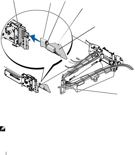
NOTE: Both the right and left cable-management arm ramp assemblies are illustrated in Figure 1-1. Depending on the orientation of the cable-management arm (CMA), you will only use one ramp assembly to secure the CMA to the back of the rack. For more information, see "Attaching the Cable-Management Arm Ramp Assembly"
on page 19.
Rack Installation Guide |
|
7 |
|
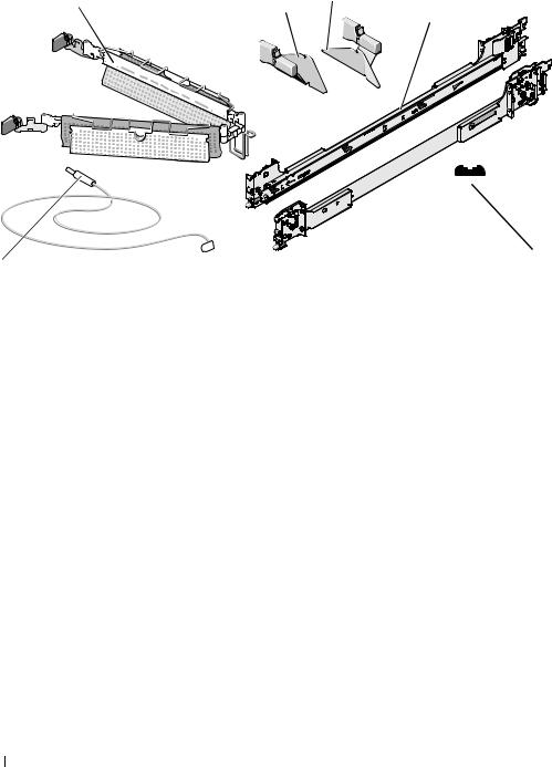
Figure 1-1. Rack Kit Contents
1 |
3 |
2 |
4
|
|
|
|
|
|
|
|
6 |
|
|
|
|
5 |
||
|
|
|
|
|
|
|
|
1 |
cable-management arm |
2 |
left cable-management arm |
3 |
right cable-management arm |
||
|
|
|
ramp assembly |
|
ramp assembly |
||
4 |
slide assemblies |
5 |
10-32 x 0.5-inch flange-head |
6 |
status indicator cable |
||
|
|
|
Phillips screws (8) |
|
(if applicable) |
||
Installation Tasks
Installing a rack kit involves performing the following tasks (described in detail in subsequent sections) in their numbered order:
1Removing the rack doors
2Marking the rack
3Configuring the sliding rail assemblies
4Installing the mounting rails in the rack
•RapidRails installation
•VersaRails installation
5Installing the system in the rack
6Installing the cable-management arm
7Routing cables
8Attaching the cable-management arm ramp assembly
9Replacing the rack doors
8 Rack Installation Guide
Removing the Rack Doors
See the procedures for removing doors in the documentation provided with your rack cabinet.
CAUTION: Because of the size and weight of the rack cabinet doors, never attempt to remove or install them by yourself.
CAUTION: Store the doors where they will not injure someone if the doors accidently fall over.
Marking the Rack
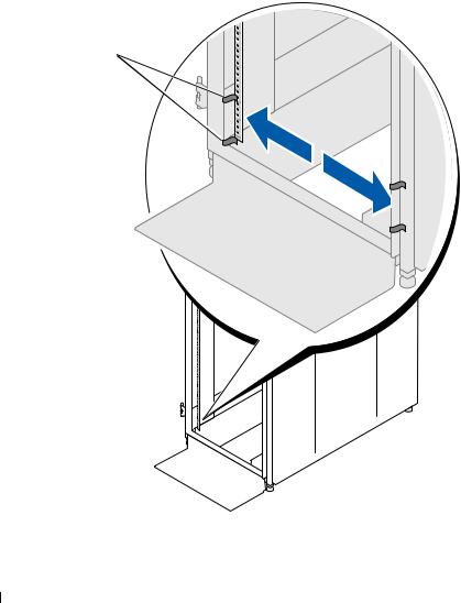
For a 2-U system, you must allow 2 U (88 mm, or 3.5 inches) of vertical space for each system you install in the rack.
Rack cabinets that meet EIA-310 standards have an alternating pattern of three holes per rack unit with center-to-center hole spacing (beginning at the top hole of a 1-U space) of 15.9 mm, 15.9 mm, and 12.7 mm (0.625 inch, 0.625 inch, and 0.5 inch) for the front and back vertical rails (see Figure 1-2). Rack cabinets may have round or square holes.
NOTE: The vertical rails may be marked by horizontal lines and numbers in 1-U increments. If you want, you can make a note of the number marking on the rack’s vertical rail. It is not necessary to mark or place tape on the rack.
Figure 1-2. One Rack Unit
12.7 mm (0.5 inch)
15.9 mm (0.625 inch)
1 U (44 mm [1.75 inches])
15.9 mm (0.625 inch)
12.7 mm (0.5 inch)
CAUTION: If you are installing more than one system, install the mounting rails so that the first system is installed in the lowest available position in the rack.
Rack Installation Guide |
|
9 |
|
To mark the rack, perform the following steps:
1Place a mark (or tape) on the rack's front vertical rails where you want to locate the bottom of the system you are installing in the rack. The bottom of each 1-U space is at the middle of the narrowest metal area between holes (marked with a horizontal line on some rack cabinets—see Figure 1-3).
2Place a mark 88 mm (3.5 inches) above the original mark you made (or count up three holes in a rack that meets EIA-310 standards) and mark the rack's front vertical rails with a felt-tipped pen or masking tape (if you counted holes, place a mark just above the top hole). This mark or piece of tape indicates where the system's upper edge will be located on the vertical rails (see Figure 1-3).
Figure 1-3. Marking the Vertical Rails
1 
1 marks on vertical rail (2)
10 Rack Installation Guide
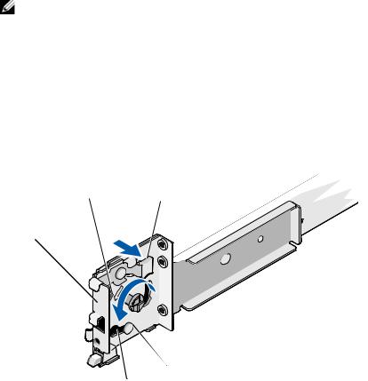
Configuring the Sliding Rail Assemblies
The sliding rail assembly has a rotating mounting bracket at each end of the rail. The position of the bracket determines whether the rail assembly is used as a RapidRail or a VersaRail. The RapidRail side of the bracket has a hook and a latch that secure it to the vertical rail. The VersaRail side of the bracket has three holes and uses screws to attach it to the vertical rail.
NOTE: The rack kit ships with the slide assemblies in the RapidRails configuration.
To change from one type of rail assembly to the other type of rail assembly:
1Lift the blue lever on the rotating mounting bracket (see Figure 1-4).
2Rotate the bracket and slide it up off of the two shoulder standoffs.
3Continue to rotate the bracket 180 degrees until you can set the notches back over the shoulder standoffs.
4Rotate the bracket in the opposite direction until the bracket clicks into place.
Figure 1-4. Changing the Position of the Rotating Mounting Bracket
1 |
2 |
|
5
3
|
4 |
|
|
|
|
1 |
mounting-bracket flange |
2 |
rotating bracket |
3 |
release lever |
|
(RapidRails version shown) |
|
|
|
|
4 |
shoulder standoffs (2) |
5 |
notches (2) |
|
|
Rack Installation Guide |
|
11 |
|

Installing the Mounting Rails in the Rack
Installing RapidRails Mounting Rails
NOTE: Ensure that the rotating mounting brackets on the slide assemblies are in the RapidRail configuration. See Figure 1-5.
1At the front of the rack cabinet, position one of the mounting rails so that its mounting-bracket flange fits between the marks or tape you placed (or numbered locations) on the vertical rails in "Marking the Rack" on page 9 (see Figure 1-5).
The top mounting hook on the front mounting-bracket flange should enter the top hole between the marks you made on the vertical rails.
Figure 1-5. Installing RapidRails Mounting Rails
1
2
3 


front of rack
1 mounting hooks (4) |
2 |
push buttons (2) |
3 |
mounting rails (2) |
12 Rack Installation Guide

2Push the mounting rail forward until the mounting hooks enter their square holes, and then push down on the mounting-bracket flange until the mounting hooks seat and the push button pops out and clicks (see Figure 1-5).
3At the back of the cabinet, pull back on the mounting-bracket flange until the mounting hooks enter their square holes, and then push down on the flange until the mounting hooks seat and the push button pops out and clicks.
4Repeat step 1 through step 3 for the mounting rail on the other side of the rack.
NOTE: Ensure that the mounting rails are mounted at the same vertical position on both sides of the rack.
Installing the VersaRails Mounting Rails
NOTE: Ensure that the rotating mounting brackets on the slide assemblies are in the VersaRail configuration. See Figure 1-6.
1At the front of the rack cabinet, position one of the mounting rails so that its mounting-bracket flange fits between the marks you placed (or numbered locations) on the vertical rails in "Marking the Rack" on page 9 (see Figure 1-6).
The three holes on the front of the mounting-bracket flange should align with the holes between the marks you made on the front vertical rail.
2Install two 10-32 x 0.5-inch flange-head Phillips screws in the upper and lower holes in the mountingbracket flange to secure the mounting rail to the front vertical rail.
3At the back of the cabinet, pull back on the mounting-bracket flange until the mounting holes align with their respective holes on the back vertical rail.
4Install two 10-32 x 0.5-inch flange-head Phillips screws in the upper and lower holes in the mountingbracket flange to secure the mounting rail to the back vertical rail.
5Repeat step 1 through step 4 for the mounting rail on the other side of the rack.
NOTE: Ensure that the mounting rails are mounted at the same position on the vertical rails on each side of the rack.
Rack Installation Guide |
|
13 |
|
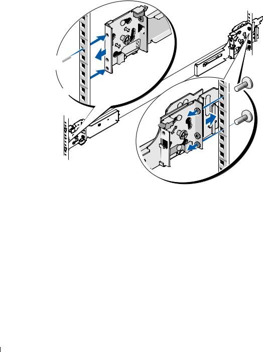
Figure 1-6. Installing VersaRails Mounting Rails
1
2
3

front of rack
1 mounting-bracket flange |
2 |
10-32 x 0.5-inch flange-head Phillips |
3 |
mounting rails (2) |
|
|
screws (4 per mounting rail) |
|
|
14 Rack Installation Guide

Installing the System in the Rack
CAUTION: If you are installing more than one system, install the first system in the lowest available position in the rack.
CAUTION: Because of the size and weight of the system, never attempt to install the system in the mounting rails by yourself.
1Pull the two inner slide rails out of the rack until they lock in the fully extended position.
2Lift the system into position above the extended slides.
The three shoulder screws on the sides of the system fit into the corresponding J-slots (see detail on Figure 1-7) on the inner slide assemblies.
3Lower the back of the system while aligning the back shoulder screws on the sides of the system with the back J-slots on the slide assemblies.
4Engage the back shoulder screws into their respective J-slots.
5Lower the front of the system and fit the middle and front shoulder screws into the J-slots in the slide assemblies.
The system release latch at the front of the inner slide rail will snap back as the shoulder screw passes into the front slot. Use this system release latch when you wish to remove the system from the slide assemblies.
6Press the slide-release latch on the outside of each inner slide, then push the system into the rack.
7Install the cable-management arm. See "Installing the Cable-Management Arm" on page 17.
8Tighten the thumbscrews on the rack front panel to secure the slide assemblies to the rack.
Rack Installation Guide |
|
15 |
|
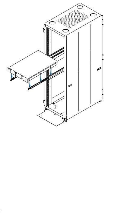
Figure 1-7. Installing the System in the Rack
 1
1
 2
2
|
|
|
|
|
3 |
|
|
|
4 |
|
|
1 |
slide-release latch |
2 |
shoulder screws (6) |
3 |
J slots (6) |
4 |
front release latch |
|
|
|
|
Removing the System From the Rack
To remove the system from the rack, perform the following procedure:
1Turn off the system and attached peripherals, and disconnect the system from the electrical outlet.
2Remove the I/O cable connectors and power cable connectors from their respective connectors on the system back panel.
3Loosen the thumbscrews on each side of the front chassis panel that secures the system to the rack.
16 Rack Installation Guide
4Pull the system out of the rack until it stops because of the safety catch.
5Pull up on the front release latch on each rail to disengage the safety catch (see Figure 1-7) and slide the system forward.
6Pull the system completely out of the rack.
Installing the Cable-Management Arm
NOTE: You can attach the cable-management arm to either side of the rack cabinet.
NOTE: Attach the cable-management arm ramp assembly to the side opposite of where you attach the cablemanagement arm.
1Fit the latch on the front end of the cable-management arm onto the bracket on the end of the mounting rail until the latch clicks (see Figure 1-8).
2Fit the latch on the unattached end of the cable-management arm onto the bracket on the end of the slide assembly until the latch clicks (see Figure 1-8).
CAUTION: Both ends of the cable-management arm must be connected before you begin routing the system cables.
Figure 1-8. Installing the Cable-Management Arm
1 2
 3
3
back of system
4
1 |
mounting rails (2) |
2 |
brackets (2) |
3 |
latches (2) |
4 |
cable-management arm |
Rack Installation Guide |
|
17 |
|
Routing Cables
1Open the wire cable basket on the top of the cable-management arm, to enable cables to be routed within the arms (see Figure 1-9).
Figure 1-9. Routing Cables on the Cable-Management Arm
1
2
|
|
|
4 |
3 |
|
|
|
|
|
1 |
tie wraps (2) |
2 |
|
system status-indicator cable connector |
3 |
cable-management arm |
4 |
|
wire cable basket |
2If applicable, connect the system status-indicator cable to its connector on the system back panel.
Route the system status-indicator cable through the cable-management arm, and press the LED end into the slot on the end of the cable-management arm until it snaps into place.
3Attach the I/O cable connectors and power cable connectors to their respective connectors on the system back panel.
For details on cable connections, see your system’s Getting Started Guide or Hardware Owner’s Manual.
NOTE: Use the retainer brackets on the back of the power supplies to provide strain relief for the power cables.
4Route the cables along the bend in the cable-management arm.
5Adjust the cable slack as needed at the hinge position and secure the cables with the tie wraps (see Figure 1-9).
6Close the cable basket.
18 Rack Installation Guide
7Slide the system in and out of the rack to verify that the cables are routed correctly and do not bind, stretch, or interfere with the movement of the cable-management arm. Adjust the cable positioning inside the cable-management arm as needed.
NOTE: If you pull the system out to its furthest extension, the slide assemblies will lock in the extended position. To release the lock, press the slide release latch on the side of each slide and then slide the system into the rack.
8 When you are satisfied that the cables are routed correctly, push the system fully into the rack.
Attaching the Cable-Management Arm Ramp Assembly
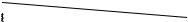
The cable-management arm ramp assembly guides the cable-management arm into a stable, level position. To attach the cable-management arm ramp assembly:
1Select only one ramp assembly, depending on the orientation of the cable-management arm.
a If the cable-management arm is attached on the right side of the rack (as shown in Figure 1-11), attach the left cable-management arm ramp assembly to the rack (see Figure 1-10).
b If the cable-management arm is attached on the left side of the rack, attach the right cablemanagement arm ramp assembly to the rack (see Figure 1-10).
CAUTION: The cable-management arm ramp assembly must be installed to prevent long-term sagging of the cable-management arm.
NOTE: Ensure that you use the cable-management arm ramp assembly with the metal ramp facing toward the center of the rack (see Figure 1-10).
NOTE: The orientation shown in Figure 1-10 presumes you are facing the back of the system.
Figure 1-10. Orientation for the Left or Right Cable-Management Arm Ramp Assembly
2
1
|
|
3 |
|
|
1 left cable-management arm |
2 |
right cable-management arm |
3 |
metal ramp |
ramp assembly |
|
ramp assembly |
|
|
Rack Installation Guide |
|
19 |
|
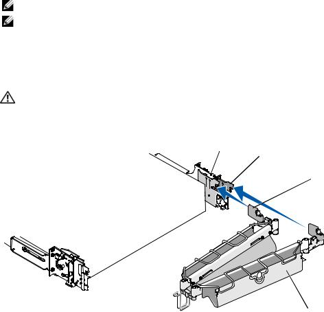
2Fit the latch of the ramp assembly on the ramp assembly bracket, located on the opposite side of the rack from where you attached the cable-management arm (see Figure 1-11).
3To slide the cable-management arm into place:
a Locate the ramp assembly wireform guide at the bend of the cable-management arm.
b Lift and slide the ramp assembly wireform guide up the ramp, stopping at the ramp assembly seating catch.
cIf you have selected the correct ramp assembly, the wireform guide will seat correctly in the catch at the top of the ramp assembly each time the system is cycled in the rack. Figure 1-11 shows the left ramp assembly installed with the cable-management arm attached on the right.
To disengage the cable-management arm ramp assembly, press the ramp assembly release button on the ramp assembly latch and pull the ramp assembly off the bracket (see Figure 1-11).
Figure 1-11. Installing the Cable-Management Arm Ramp Assembly
1 |
3 |
|
2 |
4
 5
5
|
|
|
|
6 |
|
1 |
ramp assembly bracket |
2 |
cable-management arm ramp |
3 |
ramp assembly release button |
|
|
|
assembly latch |
|
|
4 |
ramp assembly seating catch |
5 |
left cable-management arm |
6 |
ramp assembly wireform |
|
|
|
ramp assembly |
|
guide |
NOTE: In Figure 1-11, the cable-management arm is attached on the right side of the rack and the left cablemanagement arm ramp assembly is attached to the left side of the rack. Conversely, if you attach the cablemanagement arm on the left side of the rack, attach the right cable-management arm ramp assembly to the right side of the rack.
20 Rack Installation Guide

Replacing the Rack Doors
See the procedures for replacing doors in the documentation provided with your rack.
CAUTION: Because of the size and weight of the rack cabinet doors, never attempt to remove or install them by yourself.
Rack Installation Guide |
|
21 |
|

22 Rack Installation Guide
Guide d'installation du rack

Remarques, avis et précautions
REMARQUE : une REMARQUE indique des informations importantes qui peuvent vous aider à mieux utiliser votre ordinateur.
AVIS : un AVIS vous avertit d'un risque de dommage matériel ou de perte de données et vous indique comment éviter le problème.
 PRÉCAUTION : une PRÉCAUTION indique un risque potentiel d'endommagement du matériel, de blessure corporelle ou de mort.
____________________
Les informations contenues dans ce document peuvent être modifiées sans préavis. © 2007 Dell Inc. Tous droits réservés.
La reproduction de ce document de quelque manière que ce soit sans l'autorisation écrite de Dell Inc. est strictement interdite.
Marques utilisées dans ce document : Dell, le logo DELL, RapidRails et VersaRails sont des marques de Dell Inc.
Tous les autres noms de marques et marques commerciales utilisés dans ce document se rapportent aux sociétés propriétaires de ces marques et de ces noms ou à leurs produits. Dell Inc. décline tout intérêt dans l'utilisation des marques déposées et des noms de marques ne lui appartenant pas.
Mars 2007 |
P/N TP579 |
Rev. A00 |

Sommaire
Consignes de sécurité . . . . . . . . . . . . . . . . . . . . . . . . . . . . . . |
27 |
SÉCURITÉ : montage en rack des systèmes . . . . . . . . . . . . . . . . |
27 |
Consignes générales d'installation . . . . . . . . . . . . . . . . . . . . . . . |
28 |
Avant de commencer . . . . . . . . . . . . . . . . . . . . . . . . . . . . |
28 |
Informations importantes concernant la sécurité . . . . . . . . . . . . . |
28 |
Spécifications de rack requises pour les rails VersaRails . . . . . . . . . |
29 |
Pieds stabilisateurs du rack . . . . . . . . . . . . . . . . . . . . . . . . |
29 |
Outils et fournitures recommandés. . . . . . . . . . . . . . . . . . . . . |
29 |
Contenu du kit de rack . . . . . . . . . . . . . . . . . . . . . . . . . . . |
29 |
Tâches d'installation . . . . . . . . . . . . . . . . . . . . . . . . . . . . |
30 |
Retrait des portes du rack . . . . . . . . . . . . . . . . . . . . . . . . . . . . |
31 |
Marquage du rack . . . . . . . . . . . . . . . . . . . . . . . . . . . . . . . . |
31 |
Configuration des assemblages à glissière . . . . . . . . . . . . . . . . . . . |
33 |
Installation des rails de montage dans le rack . . . . . . . . . . . . . . . . . |
34 |
Installation des rails de montage RapidRails . . . . . . . . . . . . . . . . |
34 |
Installation des rails de montage VersaRails . . . . . . . . . . . . . . . . |
35 |
Installation du système dans le rack . . . . . . . . . . . . . . . . . . . . . . |
37 |
Retrait d'un système installé dans le rack . . . . . . . . . . . . . . . . . |
39 |
Installation du bras de gestion des câbles . . . . . . . . . . . . . . . . . . . |
39 |
Acheminement des câbles. . . . . . . . . . . . . . . . . . . . . . . . . . . . |
41 |
Installation de l'assemblage de fixation du bras de gestion des câbles. . . . |
42 |
Remise en place des portes du rack . . . . . . . . . . . . . . . . . . . . . . |
44 |
Sommaire 25

26 Sommaire

Consignes de sécurité
Respectez les consignes de sécurité de ce guide pour assurer votre sécurité personnelle et pour contribuer à protéger votre système et votre environnement de travail de dommages potentiels. Pour obtenir toutes les informations concernant la sécurité et les réglementations, consultez le document Product Information Guide (Guide d'informations sur le produit) fourni avec le système. Les informations sur
la garantie se trouvent soit dans ce document, soit à part.
SÉCURITÉ : montage en rack des systèmes
Pour garantir la stabilité du rack, ainsi que votre sécurité, respectez les précautions suivantes. Reportez-vous également à la documentation accompagnant le système et le rack pour connaître les mises en garde et les procédures spécifiques.
Les systèmes sont considérés comme étant les composants d'un rack. Le terme “composant” fait donc référence à un système mais aussi aux différents périphériques ou matériels associés.
PRÉCAUTION : avant d'installer des systèmes dans un rack autonome, installez d'abord les pieds stabilisateurs avant et latéraux. Pour plusieurs racks associés, installez d'abord les pieds stabilisateurs avant. L'installation de systèmes dans un rack non équipé de pieds stabilisateurs peut provoquer son basculement et entraîner des blessures. Installez toujours les pieds stabilisateurs du rack avant d'ajouter des composants dans celui-ci.
Après avoir installé un système ou des composants dans un rack, ne faites jamais coulisser hors du rack plus d'un composant à la fois. Le poids de plusieurs composants sortis du rack risquerait de le faire basculer et de blesser quelqu'un gravement.
REMARQUE : le système est certifié sur le plan de la sécurité en tant qu'unité autonome et en tant que composant destiné à être utilisé dans un rack Dell, à l'aide du kit de rack client. L'installation du système et du kit d'installation en rack dans une autre armoire n'a reçu aucune homologation des organismes de certification de la sécurité.
Il vous incombe de veiller à ce que la combinaison finale système et rack soit conforme à toutes les normes de sécurité en vigueur, ainsi qu'aux normes électriques locales. Dell décline toute responsabilité et toutes garanties liées à ce type de combinaisons.
•Les kits de rack doivent être installés par des techniciens de maintenance qualifiés. Si vous installez ce kit dans un autre rack, assurez-vous que ce dernier possède les mêmes spécifications qu'un rack Dell.
PRÉCAUTION : ne déplacez pas de rack sans aide. En raison de la hauteur et du poids du rack, cette tâche doit être réalisée par deux personnes au minimum.
•Avant de travailler sur le rack, vérifiez que les pieds stabilisateurs sont fixés au rack, qu'ils touchent le sol et que tout le poids du rack repose sur le sol. Avant d'intervenir sur un rack isolé, installez d'abord les pieds stabilisateurs avant et latéraux. Pour plusieurs racks associés, installez d'abord les pieds stabilisateurs avant.
•Chargez le rack du bas vers le haut, en plaçant toujours l'élément le plus lourd en premier.
•Assurez-vous que le rack est d'aplomb et stable avant de tirer un composant hors de son compartiment.
•Agissez avec précaution lorsque vous appuyez sur les loquets d'éjection des rails pour insérer ou retirer un composant. Veillez notamment à ne pas coincer vos doigts dans les rails coulissants.
Guide d'installation du rack |
|
27 |
|

•Ne surchargez pas le circuit d'alimentation secteur du rack. La consommation totale du rack ne doit pas dépasser 80 % de la capacité du circuit.
•Assurez-vous que les éléments installés dans le rack sont suffisamment ventilés.
•Ne montez pas sur un composant lorsque vous intervenez sur d'autres composants du rack.
Consignes générales d'installation
Ce guide d'installation s'adresse à des techniciens de maintenance qualifiés. Il contient les instructions relatives à l'installation d'un ou de plusieurs systèmes dans un rack. La configuration RapidRails™ peut être installée sans outils dans tous les racks du fabricant dotés de trous carrés ; la configuration VersaRails™ peut être installée dans la plupart des racks standard équipés de trous carrés ou ronds. Un kit d'installation est nécessaire pour chaque système.
Avant de commencer
Avant de commencer à installer le système dans le rack, lisez attentivement la section “Consignes de sécurité” à la page 27, ainsi que les consignes de sécurité figurant dans le document Product Information Guide (Guide d'informations sur le produit) pour plus d'informations.
PRÉCAUTION : si vous installez plusieurs systèmes dans un rack, terminez toutes les opérations requises sur le système en cours d'installation avant de passer au suivant.
PRÉCAUTION : les racks peuvent être extrêmement lourds, mais se déplacent assez facilement sur leurs roulettes. Cependant, les roulettes ne possèdent pas de système de freinage. Procédez avec la plus grande prudence pour déplacer un rack. Rentrez ses pieds réglables lorsque vous le changez d'emplacement. Évitez de déplacer le rack le long de rampes ou de plans inclinés trop longs ou trop abrupts, sur lesquels l'armoire pourrait vous échapper. Ressortez les pieds réglables lorsque l'armoire doit être soutenue ou pour lui éviter de glisser sur ses roulettes.
REMARQUE : pour plus d'informations sur l'installation du système proprement dit, voir “Installation du système dans le rack” à la page 37.
Informations importantes concernant la sécurité
Respectez les précautions décrites dans les sous-sections suivantes lors de l'installation du système dans le rack.
PRÉCAUTION : vous devez respecter à la lettre les procédures de ce document afin de garantir votre propre protection ainsi que celle d'autrui. Le système peut être très lourd et volumineux. Une préparation et une planification adéquates sont donc importantes afin d'éviter tout risque de blessure pour vous-même ou autrui. Ces précautions sont d'autant plus importantes lorsque les systèmes sont installés en hauteur.
PRÉCAUTION : n'installez pas de kits prévus pour un autre système. Sinon, vous risquez d'endommager le système et de vous blesser ou de blesser une autre personne.
28 Guide d'installation du rack
Loading...