


SGS Thomson Microelectronics LM334Z, LM334D, LM334, LM234Z, LM234 Datasheet
...LM134-LM234
LM334
THREE TERMINAL ADJUSTABLE CURRENT SOURCES
.
.OPERATES from 1V to 40V
.0.02% V CURRENT REGULATION
.PROGRAMMABLE from 1μA to 10mA
±3% INITIAL ACCURACY
DESCRIPTION
The LM134/LM234/LM334 are 3-terminal adjustable current sources characterized by :
-an operating current range of 10000 : 1
-an excellent current regulation
-a wide dynamic voltage range of 1V to 40V
The current is determined by an external resistor without requiring other external components. Reverse voltages of up to 20V will only draw a current of several microamperes. This enables the circuit to operate asa rectifier and as a source of current in a.c. applications.
For the LM134/LM234/LM334, the voltage on the control pin is 64mV at +25oC and is directly proportionalto the absolutetemperature (oK). The simplest external resistor connection generates a current with ≈ 0.33%/oC temperature dependence. Zero drift can be obtainedby adding an additionalresistor and a diode to the external circuit.
PIN CONNECTIONS
TO92
(Bottom view)
V+ |
ADJ |
V - |
2 |
1 |
3 |
Z
TO92
(Plastic Package)
D
SO8
(Plastic Micropackage)
ORDER CODES
Part Num- |
Temperature |
ber |
Range |
LM134 |
±55oC, +125oC |
LM234 |
±25oC, +100oC |
LM334 |
0oC, +70oC |
Example : LM134Z |
|
SO8
(Top view)
N C |
N C |
V- |
N C |
8 |
7 |
6 |
5 |
Package
ZD
••
••
••
1 |
2 |
3 |
4 |
ADJ |
NC |
NC |
V+ |
October 1997 |
1/10 |
LM134-LM234-LM334
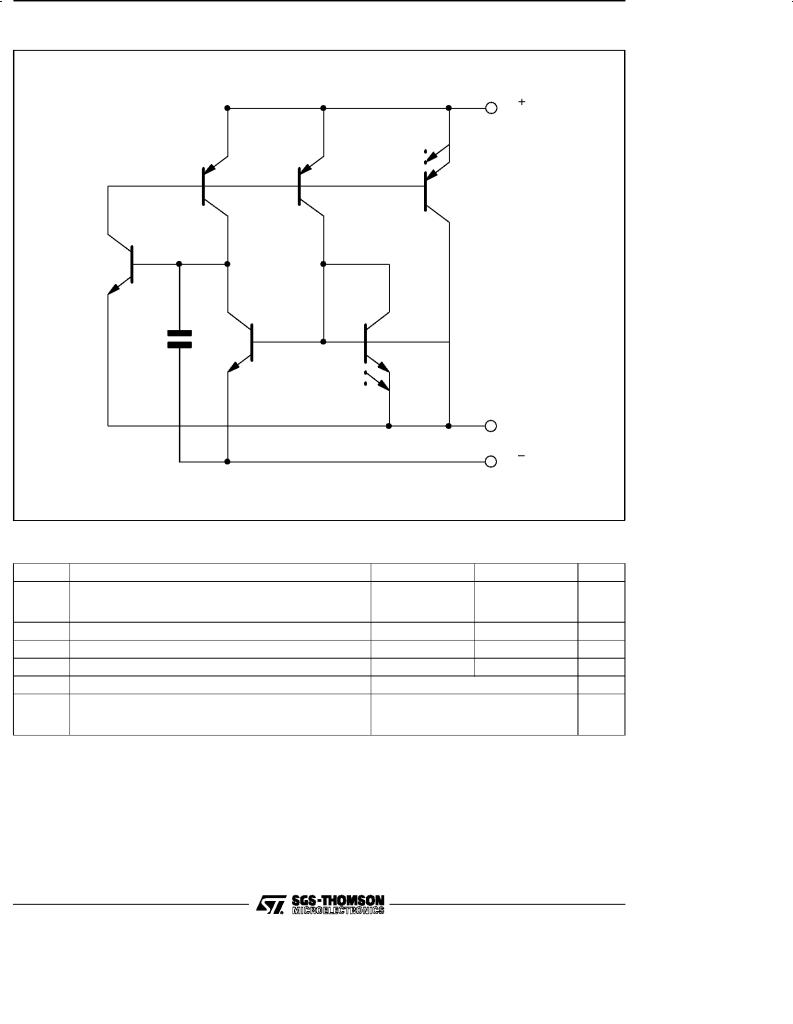
SCHEMATIC DIAGRAM
V
Q4 |
Q5 |
Q6 |
Q3
C1 Q1
Q2
50pF
ADJ
V
ABSOLUTE MAXIMUM RATING
Symbol |
|
|
Parameter |
|
LM134 - LM234 |
LM334 |
Unit |
|
Voltage V + to V ± |
|
|
|
V |
||
|
Forward |
|
|
|
40 |
30 |
|
|
Reverse |
|
|
|
20 |
20 |
|
- |
ADJ Pin to V |
± |
Voltage |
|
5 |
5 |
V |
VADJ |
|
|
|||||
ISET |
Set Current |
|
|
|
10 |
10 |
mA |
Ptot |
Power Dissipation |
|
400 |
400 |
mW |
||
Tstg |
Storage Temperature Range |
|
±65 to +150 |
|
oC |
||
Toper |
Operating Free-air Temperature Range |
LM134 |
±55 to +125 |
|
oC |
||
|
|
|
|
LM234 |
±25 to +100 |
|
|
|
|
|
|
LM334 |
0 to +70 |
|
|
2/10

LM134-LM234-LM334
ELECTRICAL CHARACTERISTICS
Tj = +25oC with pulse testing so that junction temperature does not change during testing (unless otherwise specified)
|
|
|
|
Parameter |
LM134 - LM234 |
|
LM334 |
Unit |
||
|
|
|
|
Min. |
Typ. |
Max. |
Min. |
Typ. |
||
|
|
|
|
|
Max. |
|||||
Set Current Error (V+ = +2.5V) - (note 1) |
|
|
|
|
|
% |
||||
10μA ≤ ISET ≤ 1mA |
|
|
3 |
|
|
6 |
||||
1mA |
≤ ISET ≤ |
5mA |
|
|
5 |
|
|
8 |
||
2μA |
≤ ISET ≤ |
10μA |
|
|
8 |
|
|
12 |
||
Ratio of Set Current to V± Current |
|
|
|
|
|
|
||||
10μA ≤ ISET ≤ 1mA |
14 |
18 |
23 |
14 |
18 |
26 |
||||
1mA |
≤ ISET ≤ |
5mA |
|
14 |
|
|
14 |
|
||
2μA |
≤ ISET ≤ |
10μA |
|
14 |
|
|
14 |
|
||
Minimum Operating Voltage |
|
|
|
|
|
V |
||||
2μA |
≤ ISET ≤ |
100μA |
|
0.8 |
|
|
0.8 |
|
||
100μA ≤ ISET ≤ |
1mA |
|
0.9 |
|
|
0.9 |
|
|||
1mA |
≤ ISET ≤ |
5mA |
|
1 |
|
|
1 |
|
||
Average change in set current with input voltage |
|
|
|
|
|
% / V |
||||
2μA |
≤ ISET ≤ |
1mA |
|
|
|
|
|
|
||
|
+1.5V |
≤ |
V+ |
≤ +5V |
|
0.02 |
0.05 |
|
0.02 |
0.1 |
|
+5V ≤ |
V+ ≤ |
+40V |
|
0.01 |
0.03 |
|
0.01 |
0.05 |
|
1mA ≤ ISET ≤ 5mA |
|
|
|
|
|
|
||||
|
+1.5V |
≤ V+ |
+ ≤ +5V |
|
0.03 |
|
|
0.03 |
|
|
|
+5V ≤ |
V+ ≤ |
+40V |
|
0.02 |
|
|
0.02 |
|
|
Temperature Dependence of set current - (note 2) |
|
|
|
|
|
|
||||
25μA ≤ ISET ≤ 1mA |
0.96 T |
T |
1.04 T |
0.96 T |
T |
1.04 T |
||||
Effective Shunt Capacitance |
|
15 |
|
|
15 |
pF |
||||
Notes : 1. Set current |
is the current flowing into theV+ pin. It is determined by the following formula Iset = 67.7mV/Rset |
(Tj = +25oC). |
|
Set current |
error is expressed as a percent deviation from this amount. |
2.Iset is directly proportional to absolute temperature (oK). Iset at any temperature can be calculated from Iset = IO (T/TO) where IO is Iset measured at TO (oK).
3/10
 Loading...