


Philips PCA84C640, PCA84C641, PCA84C644, PCA84C440, PCA84C441 Datasheet
...INTEGRATED CIRCUITS
DATA SHEET
84C44X; 84C64X; 84C84X
8-bit microcontrollers with OSD and VST
Product specification |
1996 Nov 29 |
Supersedes data of October 1994
File under Integrated Circuits, IC14

Philips Semiconductors |
|
Product specification |
||
|
|
|||
8-bit microcontrollers with OSD and VST |
84C44X; 84C64X; 84C84X |
|||
|
|
|
||
|
|
|
||
CONTENTS |
13 |
EMULATION MODE |
||
1 |
FEATURES |
14 |
REGISTER MAP |
|
15 |
LIMITING VALUES |
|||
1.1 |
PCF84CXXXA kernel |
|||
16 |
DC CHARACTERISTICS |
|||
1.2 |
Derivative features PCA84C640 |
|||
2 |
GENERAL DESCRIPTION |
17 |
AC CHARACTERISTICS |
|
2.1 |
Important note |
17.1 |
Characteristic curves |
|
3 |
ORDERING INFORMATION |
18 |
PACKAGE OUTLINE |
|
4 |
BLOCK DIAGRAM |
19 |
SOLDERING |
|
5 |
PINNING INFORMATION |
19.1 |
Introduction |
|
6 |
DIFFERENCES BETWEEN THE TYPES |
19.2 |
Soldering by dipping or by wave |
|
19.3 |
Repairing soldered joints |
|||
7 |
RESET |
|||
20 |
DEFINITIONS |
|||
7.1 |
Power-on-reset |
|||
21 |
LIFE SUPPORT APPLICATIONS |
|||
8 |
ANALOG CONTROL |
|||
22 |
PURCHASE OF PHILIPS I2C COMPONENTS |
|||
|
|
|||
8.16-bit PWM DACs
9 |
VST CONTROL |
9.114-bit PWM DAC
9.2Coarse adjustment
9.3Fine adjustment
10AFC INPUT
11INPUT/OUTPUT (I/O)
12ON SCREEN DISPLAY
12.1Features
12.2Horizontal display position control
12.3Vertical display position control
12.4Clock generator
12.5Display data registers
12.6Display control registers
12.7OSD display position
12.8OSD character size and colour selection
12.9Character ROM
1996 Nov 29 |
2 |
|
|
|
|
|
|
||
|
|
|
||
|
|
|
||
|
|
|
||
|
|
|

Philips Semiconductors |
Product specification |
|
|
8-bit microcontrollers with OSD and VST |
84C44X; 84C64X; 84C84X |
1 FEATURES
1.1PCF84CXXXA kernel
∙8-bit CPU, ROM, RAM, I/O in a single 42 leads shrink DIL package
∙Over 80 instructions all of 1 or 2 cycles
∙29 quasi-bidirectional standard I/O port lines
∙Configuration of I/O lines individually selected by mask
∙External interrupt INT/T0
∙2 direct testable inputs T0 and T1
∙8-bit programmable timer/event counter
∙3 single level vectored interrupts (external, timer/counter, I2C-bus)
∙Power-on-reset and low voltage detector
∙Single power supply
∙2 power reduction modes: Idle and Stop
∙Operating temperature range: −20 to +70 °C
∙Silicon gate CMOS fabrication process (SAC2).
1.2Derivative features PCA84C640
Although the PCA84C640 is specifically referred to throughout this data sheet, the information applies to all the devices. The small differences between the 84C640 and the other devices are specified in the text and also highlighted in Chapter 6.
The PCA84C640 comprises:
∙The PCF84CXXXA processor core
∙6 kbytes mask-programmable program ROM
∙128 bytes RAM
∙Multi-master I2C-bus interface
∙AFC input for Voltage Synthesized Tuning (VST; with 3-bit DAC and comparator)
∙On Screen Display (OSD) facility for two rows of 16-characters
∙On Screen Display character set of 64 types
∙Four programmable display dot sizes
∙Half dot character rounding
∙Seven colours for each character
∙One 14-bit PWM output for VST
∙Five 6-bit PWM outputs for analog controls
∙Eight port lines with 10 mA LED drive capability
∙18 general purpose bidirectional I/O lines plus 11 function-combined I/O lines
∙2 direct testable lines
∙Programmable VSYNCN and HSYNCN input polarity
∙RC oscillator for OSD function.
2 GENERAL DESCRIPTION
The 84C44X; 84C64X; 84C84X denotes the types:
∙PCA84C440; 84C441; 84C443; 84C444
∙PCA84C640; 84C641; 84C643; 84C644
∙PCA84C840; 84C841; 84C843; 84C844.
which are 8-bit microcontrollers with On Screen Display (OSD) and Voltage Synthesized Tuning (VST) functions. All are members of the 84CXXX microcontroller family.
There are two oscillator types for the OSD function in the various types, i.e.,
∙RC oscillator: PCA84C440; 84C443; 84C640; 84C643; 84C840; 84C843
∙LC oscillator: PCA84C441; 84C444; 84C641; 84C644; 84C841; 84C844.
2.1Important note
This data sheet details the specific properties of the PCA84C44X, PCA84C64X and PCA84C84X.
The shared characteristics of the PCA84CXXX family of microcontrollers are described in the PCF84CXXXA Family single-chip 8-bit Microcontroller of “Data Handbook IC14”, which should be read in conjunction with this data sheet.
3 ORDERING INFORMATION
TYPE NUMBER |
|
PACKAGE |
|
TEMPERATURE |
|
|
|
|
|||
NAME |
DESCRIPTION |
VERSION |
RANGE (°C) |
||
|
|||||
|
|
||||
|
|
|
|
|
|
PCA84C440; 84C443; 84C640; 84C643; |
|
|
|
|
|
84C840; 84C843 |
SDIP42 |
plastic shrink dual in-line |
SOT270-1 |
−20 to +70 |
|
|
|||||
PCA84C441; 84C444; 84C641; 84C644; |
package; 42 leads (600 mil) |
||||
|
|
|
|||
84C841; 84C844 |
|
|
|
|
|
|
|
|
|
|
1996 Nov 29 |
3 |

Philips Semiconductors |
Product specification |
|
|
8-bit microcontrollers with OSD and VST |
84C44X; 84C64X; 84C84X |
|
|
4 BLOCK DIAGRAM |
|
handbook, full pagewidth |
|
T1 |
INT/T0 |
|
|
|
VOB |
VOW2 |
DOSC1 VSYNCN |
|||
|
|
|
|
|
|
|
|
|
|
|||
|
|
(6) |
|
|
|
|
VOW1 |
VOW3 |
DOSC2 |
HSYNCN |
||
|
|
|
|
|
|
|
|
|
|
(3) |
|
|
|
|
|
|
|
|
|
|
|
|
|
|
|
XTAL1 (IN) |
|
|
|
|
|
|
|
|
|
|
|
|
|
8-BIT |
|
|
ROM |
RAM |
|
|
|
|
|
|
|
|
TIMER / |
CPU |
|
|
ON SCREEN DISPLAY |
|
||||||
|
|
(1) |
(2) |
|
|
|||||||
|
EVENT |
|
|
|
||||||||
XTAL2 (OUT) |
|
|
|
|
|
|
|
|
|
|
||
COUNTER |
|
|
|
|
|
|
|
|
|
|||
|
|
|
|
|
|
|
|
|
|
|||
|
|
|
|
|
|
|
|
|
|
|
8-bit internal bus |
|
RESET |
|
|
|
|
|
|
|
|
|
|
|
|
|
PARALLEL |
|
|
|
|
|
|
|
|
|
||
|
|
I/O |
84CXXX |
8-BIT |
6-BIT |
14-BIT |
3-BIT DAC + |
|
I2C |
|||
|
|
core |
|
|||||||||
TEST/EMU |
PORTS |
I/O |
DAC |
DAC |
COMPARATOR |
INTERFACE |
||||||
|
|
excluding |
PORTS |
|||||||||
|
|
|
|
|
|
|
|
|
|
|||
|
|
|
ROM/RAM |
|
|
|
|
|
|
|
|
|
|
|
8 |
5 |
8 |
8 |
|
|
|
|
|
|
MCD170 |
|
|
|
|
|
|
|
|
|
||||
|
P0 |
P1 |
|
DP0 |
DP1 |
1 2 3 4 5 |
TDAC |
|
AFC |
|
SDA |
SCL |
|
|
|
|
|
(5) |
PWM |
|
|
|
|
|
(4) |
|
|
|
|
|
|
|
|
|
|
|
||
(1) 4 kbytes for the PCA84C440; 84C441; 84C443; 84C444. |
|
|
|
|
|
|
|
|
|
|||
6 kbytes for the PCA84C640; 84C641; 84C643; 84C644.
8 kbytes for the PCA84C840; 84C841; 84C843; 84C844.
(2)128 bytes for the PCA84C440; 84C441; 84C443; 84C444; 84C640; 84C641; 84C643; 84C644. 192 bytes for the PCA84C840; 84C841; 84C843; 84C844.
(3)For use with an LC oscillator, only available with the: PCA84C441; 84C444; 84C641; 84C644; 84C841; 84C844.
(4)I2C-bus interface not available with the:
PCA84C443; 84C444; 84C643; 84C644; 84C843; 84C844.
(5)DP1.4 only available for PCA84C440; 84C443; 84C640; 84C643; 84C840; 84C843.
(6)T1 = pin 29 for PCA84C440; 84C443; 84C640; 84C643; 84C840; 84C843. T1 = pin 34 for PCA84C441; 84C444; 84C641; 84C644; 84C841; 84C844.
Fig.1 Block diagram.
1996 Nov 29 |
4 |

Philips Semiconductors |
Product specification |
|
|
8-bit microcontrollers with OSD and VST |
84C44X; 84C64X; 84C84X |
|
|
5 PINNING INFORMATION |
|
andbook, halfpage |
|
|
|
|
VDD |
|||
DP0.0/TDAC |
1 |
|
42 |
|||||
|
|
|
|
|
|
|
|
|
DP0.1/PWM1 |
2 |
|
41 |
|
DP1.0 |
|||
DP0.2/PWM2 |
|
|
|
|
|
|
|
|
3 |
|
40 |
|
DP0.6/SDA |
||||
|
|
|
|
|
|
|
|
|
DP0.3/PWM3 |
4 |
|
39 |
|
DP0.7/SCL |
|||
|
|
|
|
|
|
|
|
|
|
|
|
|
|
|
|
|
|
DP0.4/PWM4 |
5 |
|
38 |
|
DP1.1 |
|||
DP0.5/PWM5 |
|
|
|
|
|
|
|
|
6 |
|
37 |
|
DP1.2 |
||||
P1.0 |
|
|
|
|
|
|
|
|
7 |
|
36 |
|
DP1.3 |
||||
|
|
|
|
|
|
|
|
|
P1.1 |
8 |
|
|
35 |
|
INT/T0 |
||
DP1.7/AFC |
|
|
|
|
|
|
|
|
9 |
|
34 |
|
DP1.4 |
||||
P1.2 |
|
PCA84C440 |
|
|
|
|
|
|
10 |
PCA84C443 |
33 |
|
RESET |
||||
|
|
|
|
|
|
|
|
|
|
|
PCA84C640 |
|
|
|
|
|
|
P1.3 |
11 |
PCA84C643 |
32 |
|
XTAL2 |
|||
|
|
|
|
|
|
|
|
|
P1.4 |
|
PCA84C840 |
|
|
|
|
|
|
12 |
31 |
|
XTAL1 |
|||||
PCA84C843 |
|
|||||||
P0.0 |
|
|
|
|
|
|
|
|
|
|
|
|
|
|
|
|
|
13 |
|
30 |
|
TEST/EMU |
||||
|
|
|
|
|
|
|
|
|
P0.1 |
14 |
|
29 |
|
T1 |
|||
|
|
|
|
|
|
|
|
|
P0.2 |
15 |
|
28 |
|
DOSC1 |
|||
|
|
|
|
|
|
|
|
|
P0.3 |
16 |
|
|
27 |
|
VSYNCN |
||
|
|
|
|
|
|
|
|
|
P0.4 |
17 |
|
26 |
|
HSYNCN |
|||
|
|
|
|
|
|
|
|
|
P0.5 |
18 |
|
25 |
|
VOB |
|||
P0.6 |
|
|
|
|
|
|
|
|
|
|
|
|
|
|
|
|
|
19 |
|
24 |
|
VOW3 |
||||
|
|
|
|
|
|
|
|
|
|
|
|
|
|
|
|
|
|
P0.7 |
20 |
|
23 |
|
VOW2/DP1.5 |
|||
VSS |
|
|
|
|
VOW1/DP1.6 |
|||
21 |
|
|
22 |
|
||||
|
|
|
|
|
|
|
|
|
|
|
MCD172 |
|
|
|
|
|
|
handbook, halfpage |
|
|
|
|
|
VDD |
|||
DP0.0/TDAC |
1 |
|
42 |
||||||
|
|
|
|
|
|
|
DP1.0 |
||
DP0.1/PWM1 |
2 |
|
41 |
|
|||||
DP0.2/PWM2 |
|
|
|
|
|
|
|
|
|
3 |
|
40 |
|
DP0.6/SDA |
|||||
|
|
|
|
|
|
|
DP0.7/SCL |
||
DP0.3/PWM3 |
4 |
|
39 |
|
|||||
|
|
|
|
|
|
|
DP1.1 |
||
DP0.4/PWM4 |
5 |
|
38 |
|
|||||
DP0.5/PWM5 |
|
|
|
|
|
|
|
|
|
6 |
|
37 |
|
DP1.2 |
|||||
P1.0 |
|
|
|
|
|
|
DP1.3 |
||
7 |
|
36 |
|
||||||
|
|
|
|
|
|
|
|
|
|
|
|
|
|
|
|
|
|
|
|
P1.1 |
8 |
|
|
|
35 |
|
INT/T0 |
||
DP1.7/AFC |
|
|
|
|
|
|
|
|
|
|
|
|
|
|
|
|
|
|
|
9 |
|
34 |
|
T1 |
|||||
P1.2 |
|
PCA84C441 |
|
|
|
|
|
|
|
10 |
PCA84C444 |
33 |
|
RESET |
|
||||
|
|
PCA84C641 |
|
|
|
|
|
|
|
P1.3 |
11 |
PCA84C644 |
32 |
|
XTAL2 |
||||
P1.4 |
|
PCA84C841 |
|
|
|
|
|
|
|
12 |
PCA84C844 |
31 |
|
XTAL1 |
|||||
P0.0 |
|
|
|
|
|
|
|
|
|
13 |
|
30 |
|
TEST/EMU |
|||||
|
|
|
|
|
|
|
|
|
|
P0.1 |
14 |
|
29 |
|
DOSC2 |
||||
|
|
|
|
|
|
|
|
|
|
|
|
|
|
|
|
|
|
|
|
P0.2 |
15 |
|
28 |
|
DOSC1 |
||||
|
|
|
|
|
|
|
|
||
P0.3 |
16 |
|
|
27 |
|
VSYNCN |
|||
|
|
|
|
|
|
|
|
|
|
P0.4 |
17 |
|
26 |
|
HSYNCN |
||||
|
|
|
|
|
|
|
|
|
|
P0.5 |
18 |
|
25 |
|
VOB |
||||
P0.6 |
|
|
|
|
|
|
|
||
|
|
|
|
|
|
|
|
|
|
19 |
|
24 |
|
VOW3 |
|||||
|
|
|
|
|
|
|
|
|
|
P0.7 |
20 |
|
23 |
|
VOW2/DP1.5 |
||||
VSS |
|
|
|
|
VOW1/DP1.6 |
||||
21 |
|
|
22 |
|
|||||
|
|
|
|
|
|
|
|
|
|
|
|
MCD171 |
|
|
|
|
|
|
|
Fig.2 Pinning diagram for PCA84CX40; 84CX43. |
Fig.3 Pinning diagram for PCA84CX41; 84CX44. |
1996 Nov 29 |
5 |

29 Nov 1996
6
Table 1 Pin description
|
|
|
SYMBOL(1) |
PIN(1) |
DESCRIPTION |
||||
|
84CX40; 84CX43 |
|
84CX41; 84CX44 |
84CX40; 84CX43 |
|
84CX41; 84CX44 |
|||
|
|
|
|
||||||
|
|
|
|
|
|
|
|||
Deviating pinning |
|
|
|
|
|
||||
|
|
|
|
|
|
||||
DP1.0 to DP1.4 |
|
DP1.0 to DP1.3 |
41, 38, 37, 36, 34 |
|
41, 38, 37, 36 |
Derivative Port 1: quasi-bidirectional I/O lines. |
|||
|
|
|
|
|
|
|
|||
T1 |
|
T1 |
29 |
|
34 |
Direct testable pin and event counter input. |
|||
|
|
|
|
|
|
|
|||
DOSC1 |
|
− |
28 |
|
− |
Connection to RC oscillator of OSD clock. |
|||
|
|
|
|
|
|
|
|||
− |
|
DOSC1/DOSC2 |
− |
|
28, 29 |
Connections to LC oscillator of OSD clock. |
|||
|
|
|
|
|
|
|
|||
Mutual pinning |
|
|
|
|
|
||||
|
|
|
|
|
|
||||
DP0.0/TDAC |
|
|
1 |
Derivative Port 0: quasi-bidirectional I/O line or 14-bit DAC PWM. |
|||||
|
|
|
|||||||
DP0.1 to DP0.5/PWM1 to PWM5 |
2 to 6 |
Derivative Port 1: quasi-bidirectional I/O lines or 6-bit DAC PWM. |
|||||||
|
|
|
|
||||||
P1.0 to P1.4 |
|
7, 8, 10, 11 and 12 |
Port 1: quasi-bidirectional I/O lines. |
||||||
|
|
|
|
||||||
P0.0 to P0.7 |
|
13 to 20 |
Port 0: quasi-bidirectional I/O port. |
||||||
|
|
|
|
|
|||||
DP1.7/AFC |
|
|
9 |
Derivative Port 1: |
|||||
|
|
|
|
|
|
|
|
|
quasi-bidirectional I/O line or comparator input with 3-bit DAC. |
|
|
|
|
||||||
DP0.6/SDA |
|
40 |
Derivative open drain I/O port or I2C-bus data line. |
||||||
|
DP0.7/SCL |
|
39 |
Derivative open drain I/O port or I2C- bus clock line. |
|||||
|
|
|
|
|
|
35 |
External interrupt or direct testable line. |
||
|
INT/T0 |
|
|||||||
|
|
|
|||||||
DP1.5 and DP1.6/VOW2 and VOW1 |
23, 22 |
Derivative Port 1: |
|||||||
|
|
|
|
|
|
|
|
|
quasi-bidirectional I/O lines or character video output. |
|
|
|
|
|
|
||||
|
|
|
|
|
|
33 |
Initialize input, active LOW. |
||
|
RESET |
|
|
|
|||||
|
|
|
|
||||||
XTAL2, XTAL1 |
|
32, 31 |
Oscillator output or input terminal for system clock. |
||||||
|
|
|
|
||||||
TEST/EMU |
|
30 |
Control input for testing and emulation mode. Ground for normal |
||||||
|
|
|
|
|
|
|
|
|
operation. |
|
|
|
|
||||||
VSYNCN |
|
27 |
Vertical synchronous signal input. |
||||||
|
|
|
|
||||||
HSYNCN |
|
26 |
Horizontal synchronous signal input. |
||||||
|
|
|
|
||||||
VOB |
|
25 |
Blanking output. |
||||||
|
|
|
|
||||||
VOW3 |
|
24 |
Character video output of OSD. |
||||||
|
|
|
|
||||||
VSS |
|
21 |
Ground. |
||||||
VDD |
|
42 |
Power supply. |
||||||
Note
1.84CX40; 84CX43 denotes the types: PCA84C440, PCA84C443, PCA84C640, PCA84C643, PCA84C840 and PCA84C843. 84CX41; 84CX44 denotes the types: PCA84C441, PCA84C444, PCA84C641, PCA84C644, PCA84C841 and PCA84C844.
VST and OSD with microcontrollers bit-8
84C84X 84C64X; 84C44X;
Semiconductors Philips
specification Product

29 Nov 1996
7
Table 2 Differences between the types PCA84C44X, PCA84C64X and PCA84C84X
In this table: yes = available; no = not available.
FEATURE |
|
|
|
|
|
PCA... |
|
|
|
|
|
||
|
|
|
|
|
|
|
|
|
|
|
|
||
84C440 |
84C441 |
84C443 |
84C444 |
84C640 |
84C641 |
84C643 |
84C644 |
84C840 |
84C841 |
84C843 |
84C844 |
||
|
|||||||||||||
|
|
|
|
|
|
|
|
|
|
|
|
|
|
OSD oscillator |
RC |
LC |
RC |
LC |
RC |
LC |
RC |
LC |
RC |
LC |
RC |
LC |
|
|
|
|
|
|
|
|
|
|
|
|
|
|
|
General purpose I/O lines |
18 |
17 |
18 |
17 |
18 |
17 |
18 |
17 |
18 |
17 |
18 |
17 |
|
|
|
|
|
|
|
|
|
|
|
|
|
|
|
I2C-bus interface |
yes |
yes |
no |
no |
yes |
yes |
no |
no |
yes |
yes |
no |
no |
|
ROM |
|
4 kbytes |
|
|
6 kbytes |
|
|
8 kbytes |
|
||||
|
|
|
|
|
|
|
|
|
|
||||
RAM |
|
128 bytes |
|
|
128 bytes |
|
|
192 bytes |
|
||||
|
|
|
|
|
|
|
|
|
|
|
|
|
|
Pin assignment |
|
|
|
|
|
|
|
|
|
|
|
|
|
|
|
|
|
|
|
|
|
|
|
|
|
|
|
Pin 29 |
T1 |
DOSC2 |
T1 |
DOSC2 |
T1 |
DOSC2 |
T1 |
DOSC2 |
T1 |
DOSC2 |
T1 |
DOSC2 |
|
|
|
|
|
|
|
|
|
|
|
|
|
|
|
Pin 34 |
DP1.4 |
T1 |
DP1.4 |
T1 |
DP1.4 |
T1 |
DP1.4 |
T1 |
DP1.4 |
T1 |
DP1.4 |
T1 |
|
|
|
|
|
|
|
|
|
|
|
|
|
|
|
Register DP1 (bit DP1.4) |
|
|
|
|
|
|
|
|
|
|
|
|
|
|
|
|
|
|
|
|
|
|
|
|
|
|
|
Pin |
yes |
no |
yes |
no |
yes |
no |
yes |
no |
yes |
no |
yes |
no |
|
|
|
|
|
|
|
|
|
|
|
|
|
|
|
Latch |
yes |
no |
yes |
no |
yes |
no |
yes |
no |
yes |
no |
yes |
no |
|
|
|
|
|
|
|
|
|
|
|
|
|
|
|
TYPES THE BETWEEN DIFFERENCES 6
VST and OSD with microcontrollers bit-8
84C84X 84C64X; 84C44X;
Semiconductors Philips
specification Product

Philips Semiconductors |
Product specification |
|
|
8-bit microcontrollers with OSD and VST |
84C44X; 84C64X; 84C84X |
|
|
7 RESET
The RESET pin (active LOW input) is used to initialize the microcontroller to a defined state. The Reset configuration is shown in Fig.5.
VDD
ndbook, halfpage
R ≤ 100 kΩ
RESET
C
MCD174 VSS
Fig.4 External components for RESET pin.
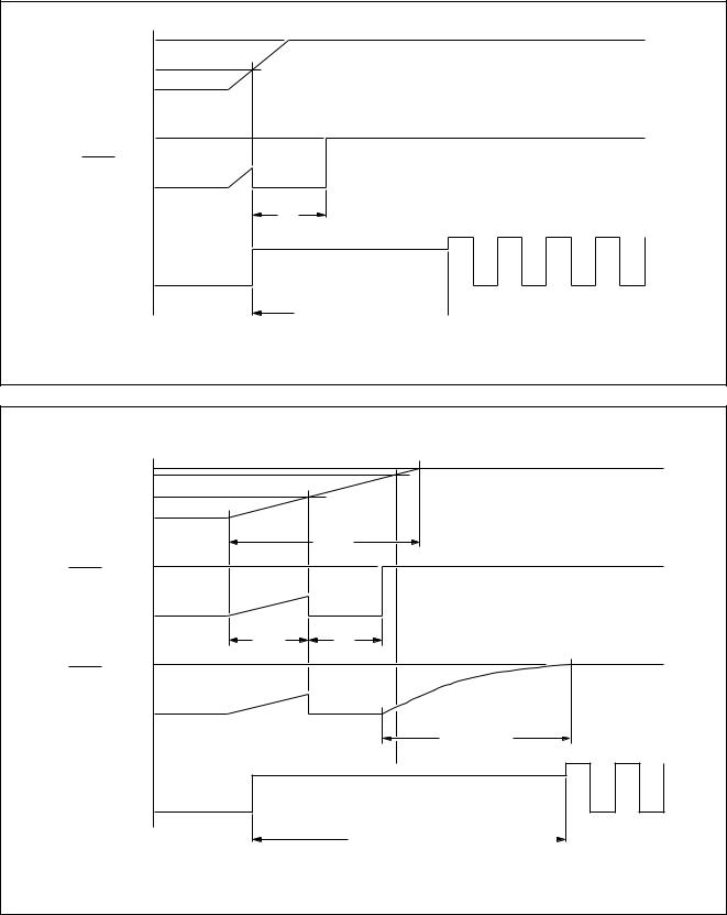
7.1Power-on-reset
The Power-on-reset circuit monitors the voltage level of VDD. If VDD remains below the internal reference voltage level Vref (typically 1.3 V), the oscillator is inhibited.
When VDD rises above Vref, the oscillator is released and the internal reset is active for a period of td (typically
50 ms).
Considering the VDD rise time, the following measures for a correct Power-on-reset can be taken:
·If the VDD rises above the minimum operation voltage before time period td is exceeded, no external components are necessary (see Fig.6).
·If VDD has a slow rise time, such that after the time period (tVref + td) has elapsed the supply voltage is still below the minimum operation voltage (Vmin),
external components are required (see Figs 4 and 7).
To guarantee a correct reset operation, ensure that the time constant RC ³ 8 ´ tVDD.
A definite Power-on-reset can be realized by applying an (external) RESET signal during power-on.
handbook, full pagewidth
VDD
oscillator inhibit
Vref  POWER-ON-RESET
RESET
internal reset
VSS
MLA651
Fig.5 Reset configuration.
1996 Nov 29 |
8 |
Philips Semiconductors |
Product specification |
|
|
8-bit microcontrollers with OSD and VST |
84C44X; 84C64X; 84C84X |
|
|
handbook, full pagewidth |
VDD |
VDD Vref
VSS
VDD
RESET
VSS
td
OSCILLATOR
MCD240
oscillator start up time 
Fig.6 Reset with fast rising VDD.
|
VDD |
|
VDD |
Vmin |
|
Vref |
|
|
|
VSS |
|
|
|
t VDD |
RESET |
VDD |
|
|
|
|
without |
|
|
external |
|
|
component |
VSS |
|
|
|
|
|
t Vref |
td |
RESET |
VDD |
|
|
|
|
with |
|
|
external |
|
|
component |
VSS |
|
|
|
|
|
|
RC ≥ 8 × tVDD |
OSCILLATOR |
|
|
oscillator start up time |
|
MCD241 |
|
|
Fig.7 Reset with slow VDD.
1996 Nov 29 |
9 |
Philips Semiconductors |
Product specification |
|
|
8-bit microcontrollers with OSD and VST |
84C44X; 84C64X; 84C84X |
|
|
8 ANALOG CONTROL
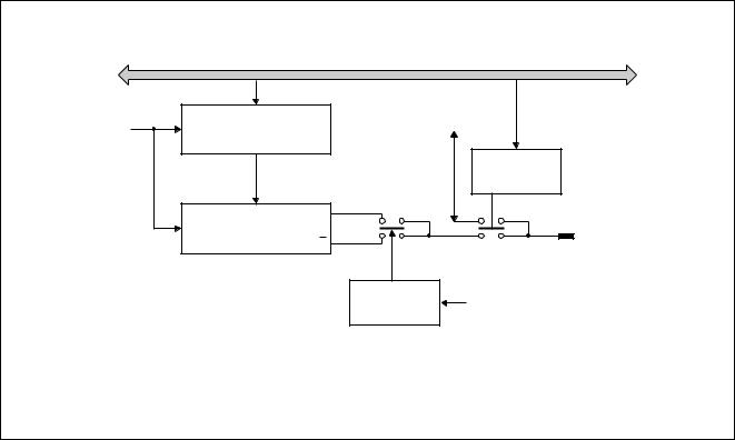
8.16-bit PWM DACs
Five PWM outputs are available for analog control purposes e.g. volume, balance, brightness, saturation, etc. The block diagram of a typical 6-bit PWM DAC is shown in Fig.8. Each PWM output can generate pulses of programmable length that have a repetition frequency of
1¤64 ´ fPWM, where fPWM = 1¤3 ´ fXTAL.
8.1.1PIN SELECTION FOR PWM OUTPUTS
The PWM outputs PWM1 to PWM5, share the same pins as the Derivative Port lines DP0.1 to DP0.5.
Setting the (relevant PWM enable) bit PWMnE to:
·Logic 1, selects the relevant PWMx output function
·Logic 0, selects the relevant DP0.x Port function.
8.1.2POLARITY OF THE PWM OUTPUTS
The polarity of all five PWM outputs is selected by the state of the polarity control bit P6LVL.
Setting the control bit P6LVL to:
·Logic 0, sets the PWMx outputs to the default polarity
·Logic 1, inverts all the PWMx outputs.
8.1.3ANALOG OUTPUT VOLTAGE
A DC voltage proportional to the PWM control setting may be obtained by connecting an integrating network to each of the PWM outputs (see Fig.9).
The analog value is calculated as follows:
tHIGH ´
VA = ------------- VO tr
Where:
·
tHIGH = t0 ´ PWMDL = HIGH time of the PWM pulse
· |
tr |
= t0 ´ 64 = repetition time of the PWM pulse |
|
· |
t0 |
= |
3 |
------------- |
|||
|
|
|
fXTAL |
·PWMDL is the decimal value of the contents of the PWM data latch.
Therefore, the analog output voltage is:
VA = |
PWMDL |
´ VO |
-----------------------64 |
handbook, full pagewidth
|
|
DP0.x data |
f PWM |
6-BIT PWM DATA LATCH |
I/O |
|
||
|
|
PWMnE |
|
Q |
|
|
6-BIT DAC PWM |
|
|
CONTROLLER |
DP0.x/PWMx |
|
Q |
|
|
P6LVL |
polarity control bit |
|
|
MCD176 |
Fig.8 Block diagram of the 6-bit PWM DAC.
1996 Nov 29 |
10 |
Philips Semiconductors |
Product specification |
|
|
8-bit microcontrollers with OSD and VST |
84C44X; 84C64X; 84C84X |
|
|
|
t 0 |
|
|
|
|
|
|
|
f PWM |
|
|
|
|
|
|
|
|
64 |
1 |
2 |
3 |
m |
m + 1 m + 2 |
63 |
64 |
1 |
00 |
|
|
|
|
|
|
|
|
01 |
|
|
|
|
|
|
|
|
m |
|
|
|
|
|
|
|
|
63 |
|
|
|
|
|
|
|
|
|
decimal value PWM data latch |
|
|
|
MCD175 |
|||
|
|
|
Fig.9 |
PWM output patterns (P6LVL = 0). |
|
|
|
|
1996 Nov 29 |
11 |

Philips Semiconductors |
Product specification |
|
|
8-bit microcontrollers with OSD and VST |
84C44X; 84C64X; 84C84X |
|
|
9 VST CONTROL
9.114-bit PWM DAC
The PCA84C640 has one 14-bit PWM DAC output (TDAC) with a resolution of 16384 levels for Voltage Synthesized Tuning. The PWM DAC (see Fig.10) consists of:
∙14-bit counter
∙Two 7-bit DAC interface data latches (VSTH and VSTL)
∙One 14-bit DAC data latch (VSTREG)
∙Pulse control.
The polarity of output TDAC is selected with bit P14LVL. Setting the bit P14LVL to:
∙Logic 1, sets the TDAC output to the default polarity
∙Logic 0, inverts the TDAC output.
9.1.114-BIT COUNTER
The counter is continuously running and is clocked by f0.
3 The period of the clock, t0 = -------------
fXTAL
The repetition time for one complete cycle of the counter:
tr = t0 × 16 384
The repetition time for one cycle of the lower 7-bits of the counter is:
tsub = t0 × 128
Therefore, the number of tsub periods in a complete cycle tr is:
t0 |
× 16 384 |
N = --------------------------- |
= 128 |
t0 × 128
9.1.2DATA AND INTERFACE LATCHES
In order to ensure correct operation, interface data latch VSTH is loaded first and then interface data latch VSTL. The contents of:
∙VSTH are used for coarse adjustment
∙VSTL are used for fine adjustment.
At the beginning of the first tsub period following the loading of VSTL, both data latches are loaded into data latch VSTREG. After the contents of VSTH and VSTL are latched into VSTREG, one tsub period is needed to generate the appropriate pulse pattern.
To ensure correct DAC conversion, two (2) tsub periods should be allowed before beginning the next sequence.
9.2Coarse adjustment
The coarse adjustment output (OUT1) is reset to LOW (inactive) at the start of each tsub period.
It will remain LOW until the time [ t0 × ( VSTH + 1) ] has elapsed and then will go HIGH and remain so until the next tsub period starts.
9.3Fine adjustment
Fine adjustment is achieved by generating additional pulses at the start of particular sub-periods (tsubn). These additional pulses have a width of t0.
The sub-period in which a pulse is added is determined by the contents of VSTL interface latch.
Table 3 gives the numbers of the tsubn, at the start of which an additional pulse is generated, depending on the bit in
VSTL being a logic 0. When more than one bit is a logic 0 a combination of additional pulses are generated.
For example, if VSTL = 1111010, which is a combination of
∙VSTL = 1111110: sub-period 64, and
∙VSTL = 1111011: sub-periods 16, 48, 80 and 112,
then additional pulses will be given in sub-periods 16, 48, 64, 80 and 112; this is illustrated in Fig.12.
If VSTH = 0011101, VSTL = 1111010 and P14LVL = 0, then the TDAC output is as shown in Fig.13.
Table 3 Additional pulse distribution
LOWER |
ADDITIONAL PULSE IN |
|
7 BITS |
||
SUB-PERIODS tsubn |
||
(VSTL) |
||
|
||
|
|
|
1111110 |
64 |
|
|
|
|
1111101 |
32, 96 |
|
|
|
|
1111011 |
16, 48, 80, 112 |
|
|
|
|
1110111 |
8, 24, 40, 56, 72, 88, 104, 120 |
|
|
|
|
1101111 |
4, 12, 20, 28, 36, 44, 52, 60 .... 116, 124 |
|
|
|
|
1011111 |
2, 6, 10, 14, 18, 22, 26, 30, .... 122, 126 |
|
|
|
|
0111111 |
1, 3, 5, 7, 9, 11, 13, 15, 17, .... 125, 127 |
|
|
|
1996 Nov 29 |
12 |
 Loading...