


MDS-D-SV J3
Table of contents
 Loading...

MELDAS is a registered trademark of Mitsubishi Electric Corporation.
Other company and product names that appear in this manual are trademarks or registered
trademarks of their respective companies.

Introduction
Thank you for selecting the Mitsubishi numerical control unit.
This instruction manual describes the handling and caution points for using this AC
servo/spindle.
Incorrect handling may lead to unforeseen accidents, so always read this instruction
manual thoroughly to ensure correct usage.
Make sure that this instruction manual is delivered to the end user.
Always store this manual in a safe place.
In order to confirm if all function specifications described in this manual are applicable,
refer to the specifications for each CNC.
Notes on Reading This Manual
(1) Since the description of this specification manual deals with NC in general, for the
specifications of individual machine tools, refer to the manuals issued by the
respective machine manufacturers. The "restrictions" and "available functions"
described in the manuals issued by the machine manufacturers have precedence
to those in this manual.
(2) This manual describes as many special operations as possible, but it should be
kept in mind that items not mentioned in this manual cannot be performed.

Precautions for safety
Please read this manual and auxiliary documents before starting installation, operation,
maintenance or inspection to ensure correct usage. Thoroughly understand the device, safety
information and precautions before starting operation.
The safety precautions in this instruction manual are ranked as "WARNING" and "CAUTION".
Note that some items described as
the situation. In any case, important information that must be observed is described.
The signs indicating prohibited and mandatory matters are explained below.
DANGER
WARNING
CAUTION
When there is a potential risk of fatal or serious injuries if
handling is mistaken.
When a dangerous situation, or fatal or serious injuries may
occur if handling is mistaken.
When a dangerous situation may occur if handling is mistaken
leading to medium or minor injuries, or physical damage.
CAUTION
may lead to major results depending on
Indicates a prohibited matter. For example, "Fire Prohibited"
is indicated as .
Indicates a mandatory matter. For example, grounding is
indicated as
.
After reading this specifications and instructions manual, store it where the user can access it
easily for reference.
The numeric control unit is configured of the control unit, operation board, servo drive unit,
spindle drive unit, power supply, servomotor and spindle motor, etc.
In this section "Precautions for safety", the following items are generically called the "motor".
• Servomotor
• Linear servomotor
• Spindle motor
In this section "Precautions for safety", the following items are generically called the "unit".
• Servo drive unit
• Spindle drive unit
• Power supply unit
• Scale interface unit
• Magnetic pole detection unit
POINT
Important matters that should be understood for operation of this machine
are indicated as a POINT in this manual.
1. Electric shock prevention
Do not open the front cover while the power is ON or during operation. Failure to observe this
could lead to electric shocks.
Do not operate the unit with the front cover removed. The high voltage terminals and charged
sections will be exposed, and can cause electric shocks.
Do not remove the front cover and connector even when the power is OFF unless carrying
out wiring work or periodic inspections. The inside of the units is charged, and can cause
electric shocks.
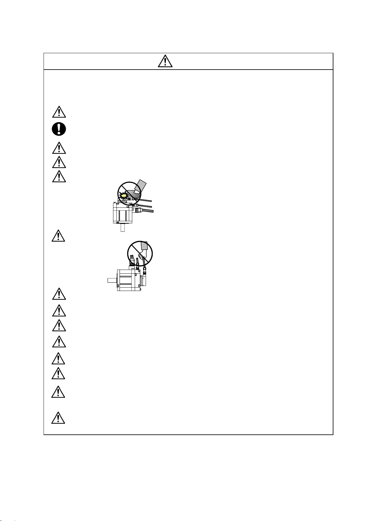
Since the high voltage is supplied to the main circuit connector while the power is ON or
during operation, do not touch the main circuit connector with an adjustment screwdriver o r
the pen tip. Failure to observe this could lead to electric shocks.
Wait at least 15 minutes after turning the power OFF, confirm that the CHARGE lamp has
gone out, and check the voltage between P and N terminals with a tester, etc., before starting
wiring, maintenance or inspections. Failure to observe this could lead to electric shocks.
Ground the unit and motor following the standards set forth by each country.
Wiring, maintenance and inspection work must be done by a qualified technician.
Wire the servo drive unit and servomotor after installation. Failure to observe this could lead to
electric shocks.
Do not touch the switches with wet hands. Failure to observe this could lead to electric shocks.
Do not damage, apply forcible stress, place heavy items on the cables or get them caught.
Failure to observe this could lead to electric shocks.
WARNING
2. Injury prevention
The linear servomotor uses a powerful magnet on the secondary side, and could adversely
affect pacemakers, etc.
During installation and operation of the machine, do not place portable items that could
malfunction or fail due to the influence of the linear servomotor's magnetic force.
Take special care not to pinch fingers, etc., when installing (and unpacking) the linear
servomotor.
In the system where the optical communication with CNC is executed, do not see directly the
light generated from CN1A/CN1B connector of drive unit or the end of cable. When the light
gets into eye, you may feel something is wrong for eye.
(The light source of optical communication corresponds to class1 defined in JIS C68 02 or
IEC60825-1.)
1. Fire prevention
Install the units, motors and regenerative resistor on non-combustible material. Direct
installation on combustible material or near combustible materials could lead to fires.
Always install a no-fuse breaker and contactor on the servo drive unit power input as explained
in this manual. Refer to this manual and select the correct no-fuse breaker and contactor. An
incorrect selection could result in fire.
Shut off the power on the unit side if a fault occurs in the units. Fires could be caused if a large
current continues to flow.
When using a regenerative resistor, provide a sequence that shuts off the power with the
regenerative resistor's error signal. The regenerative resistor could abnormally overheat and
cause a fire due to a fault in the regenerative transistor, etc.
The battery unit could heat up, ignite or rupture if submerged in water, or if the poles are
incorrectly wired.
Cut off the main circuit power with the contactor when an alarm or emergency stop occurs.
2. Injury prevention
Do not apply a voltage other than that specified in this manual, on each terminal. Failure to
observe this item could lead to ruptures or damage, etc.
CAUTION
Do not mistake the terminal connections. Failure to observe this item could lead to ruptures or
damage, etc.
Do not mistake the polarity (
damage, etc.
Do not touch the radiation fin on unit back face, regenerative resistor or motor, etc., or place
parts (cables, etc.) while the power is turned ON or immediately after turning the power OFF.
These parts may reach high temperatures, and can cause burns or part damage.
Structure the cooling fan on the unit back face, etc., etc so that it cannot be touched after
installation. Touching the cooling fan during operation could lead to injuries.
+
,
). Failure to observe this item could lead to ruptures or
CAUTION
3. Various precautions
Observe the following precautions. Incorrect handling of the unit could lead to faults, injuries and
electric shocks, etc.
(1) Transportation and installation
Correctly transport the product according to its weight.
Use the motor's hanging bolts only when transporting the motor. Do not transport the
machine when the motor is installed on the machine.
Do not stack the products above the tolerable number.
Follow this manual and install the unit or motor in a place where the weight can be borne.
Do not get on top of or place heavy objects on the unit.
Do not hold the cables, axis or detector when transporting the motor.
Do not hold the connected wires or cables when transporting the units.
Do not hold the front cover when transporting the unit. The unit could drop.
Always observe the installation directions of the units or motors.
Secure the specified distance between the units and control panel, or between the servo drive
unit and other devices.
Do not install or run a unit or motor that is damaged or missing parts.
Do not block the intake or exhaust ports of the motor provided with a cooling fan.
Do not let foreign objects enter the units or motors. In particular, if conductive objects such as
screws or metal chips, etc., or combustible materials such as oil enter, rupture or breakage
could occur.
The units and motors are precision devices, so do not drop them or apply strong impacts to
them.
CAUTION
Store and use the units under the following environment conditions.
Environment
Ambient
temperature
Ambient
humidity
Atmosphere
Altitude
Vibration/impact
(Note 1) For details, confirm each unit or motor specifications in addition.
(Note 2) -15°C to 55°C for linear servomotor.
Operation: 0 to 55°C (with no freezing),
Storage / Transportation: -15°C to 70°C
Operation: 90%RH or less
(with no dew condensation)
Storage / Transportation: 90%RH or less
(with no dew condensation)
With no corrosive gas, inflammable gas, oil mist, dust or conductive fine particles
Operation/Storage: 1000 meters or less above
Transportation: 13000 meters or less above sea
Unit Motor
(with no freezing)
sea level,
level
According to each unit or motor specification
Operation: 0 to 40°C (with no freezing),
Storage: -15°C to 70°C
Operation: 80%RH or less
(with no dew condensation),
Storage: 90%RH or less
(with no dew condensation)
Indoors (no direct sunlight)
Operation: 1000 meters or less above sea level,
Storage: 10000 meters or less above sea level
(Note 2)
(with no freezing)
Securely fix the servomotor to the machine. Insufficient fixing could lead to the servomotor
slipping off during operation.
Always install the servomotor with reduction gear in the designated direction. Failure to do so
could lead to oil leaks.
Structure the rotary sections of the motor so that it can never be touched during operation.
Install a cover, etc., on the shaft.
When installing a coupling to a servomotor shaft end, do not apply an impact by hammering,
etc. The detector could be damaged.
Do not apply a load exceeding the tolerable load onto the servomotor shaft. The shaft could
break.
Store the motor in the package box.
When inserting the shaft into the built-in IPM motor, do not heat the rotor higher than 130°C.
The magnet could be demagnetized, and the specifications characteristics will not be
ensured.
Always use a nonmagnetic tool (explosion-proof beryllium copper alloy safety tool: NGK
Insulators, etc.) when installing the linear servomotor.
Always provide a mechanical stopper on the end of the linear servomotor's travel path.
If the unit has been stored for a long time, always check the operation before starting actual
operation. Please contact the Service Center, Service Station, Sales Office or delayer.

(2) Wiring
CAUTION
Correctly and securely perform the wiring. Failure to do so could lead to abnormal operation of
the motor.
Do not install a condensing capacitor, surge absorber or radio noise filter on the output side of
the drive unit.
Correctly connect the output side of the drive unit (terminals U, V, W). Failure to do so could
lead to abnormal operation of the motor.
When using a power regenerative power supply unit, always install an AC reactor for each
power supply unit.
In the main circuit power supply side of the unit, always install an appropriate no-fuse breaker
or contactor for each unit. No-fuse breaker or contactor cannot be shared by several units.
Always connect the motor to the drive unit's output terminals (U, V, W).
Do not directly connect a commercial power supply to the servomotor. Failure to observe this
could result in a fault.
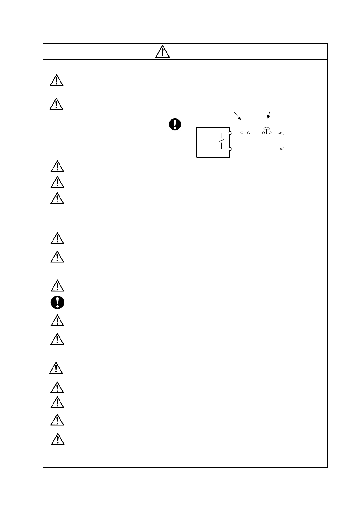
When using an inductive load such as a relay, always connect a diode as a noise measure
parallel to the load.
When using a capacitance load such as a lamp, always connect a protective resistor as a noise
measure serial to the load.
Do not reverse the direction of a diode
which connect to a DC relay for the
control output signals such as
Servodrive unit
COM
(24VDC)
Servodrive unit
COM
(24VDC)
contractor and motor brake output, etc.
to suppress a surge. Connecting it
backwards could cause the drive unit to
malfunction so that signals are not
Controloutput
signal
RA
Control output
signal
output, and emergency stop and other
safety circuits are inoperable.
RA
Do not connect/disconnect the cables connected between the units while the power is ON.
Securely tighten the cable connector fixing screw or fixing mechanism. An insecure fixing could
cause the cable to fall off while the power is ON.
When using a shielded cable instructed in the instruction manual, always ground the cable with
a cable clamp, etc.
Always separate the signals wires from the drive wire and power line.
Use wires and cables that have a wire diameter, heat resistance and flexibility that conforms to
the system.

(3) Trial operation and adjustment
Check and adjust each program and parameter before starting operation. Failure to do so could
lead to unforeseen operation of the machine.
Do not make remarkable adjustments and changes of paramete r a s the ope ration could
become unstable.
The usable motor and unit combination is predetermined. Always check the models before
starting trial operation.
If the axis is unbalanced due to gravity, etc., balance the axis using a counterbalance, etc.
The linear servomotor does not have a stopping device such as magnetic brakes. Install a
stopping device on the machine side.
(4) Usage methods
In abnormal state, install an external emergency stop circuit so that the operation can be
stopped and power shut off immediately.
Turn the power OFF immediately if smoke, abnormal noise or odors are generated from the unit
or motor.
CAUTION
Do not disassemble or repair this product.
Never make modifications.
When an alarm occurs, the machine will start suddenly if an alarm reset (RST) is carried out
while an operation start signal (ST) is being input. Always confirm that the operation signal is
OFF before carrying out an alarm reset. Failure to do so could lead to accidents or injuries.
Reduce magnetic damage by installing a noise filter. The electronic devices used near the
unit could be affected by magnetic noise. Install a line noise filter, etc., if there is a risk of
magnetic noise.
Use the unit, motor and regenerative resistor with the designated combination. Failure to do so
could lead to fires or trouble.
The brake (magnetic brake) of the servomotor are for holding, and must not be used for normal
braking.
There may be cases when holding is not possible due to the magnetic brake's life, the machine
construction (when ball screw and servomotor are coupled via a timing belt, etc.) or the
magnetic brake’s failure. Install a stop device to ensure safety on the machine side.
After changing the programs/parameters or after maintenance and inspection, always test the
operation before starting actual operation.
Do not enter the movable range of the machine during automatic operation. Never place body
parts near or touch the spindle during rotation.
Follow the power supply specification conditions given in each specification for the power (input
voltage, input frequency, tolerable sudden power failure time, etc.).
Set all bits to "0" if they are indicated as not used or empty in the explanation on the bits.
Do not use the dynamic brakes except during the emergency stop. Continued use of the
dynamic brakes could result in brake damage.
If a no-fuse breaker for the main circuit power supply is shared by several units, the no-fuse
breaker may not activate when a short-circuit fault occurs in a small capacity unit. This is
dangerous, so never share the no-fuse breakers.
(5) Troubleshooting
If a hazardous situation is predicted during power failure or product trouble, use a servomotor
with magnetic brakes or install an external brake mechanism.
Use a double circuit configuration
that allows the operation circuit for
the magnetic brakes to be operated
even by the external emergency
stop signal.
CAUTION
Shut off with the servomotor
brake control output.
Servomotor
Magnetic
brake
Shut off with NC brake
control PLC output.
MBR
EMG
24VDC
Always turn the input power OFF when an alarm occurs.
If an alarm occurs, remove the cause, and secure the safety before resetting the alarm.
Never go near the machine after restoring the power after a power failure, as the machine
could start suddenly. (Design the machine so that personal safety can be ensured even if the
machine starts suddenly.)
(6) Maintenance, inspection and part replacement
Always backup the programs and parameters before starting maintenance or i nspections.
The capacity of the electrolytic capacitor will drop over time due to self-discharging, etc. To
prevent secondary disasters due to failures, replacing this part every five years when used
under a normal environment is recommended. Contact the Service Center, Service Station,
Sales Office or delayer for repairs or part replacement.
Do not perform a megger test (insulation resistance measurement) during inspections.
If the battery low warning is issued, back up the machining programs, tool data and
parameters with an input/output unit, and then replace the battery.
Do not short circuit, charge, overheat, incinerate or disassemble the battery.
The heat radiating fin used in some units contains substitute Freon as the refrigerant.Ta ke
care not to damage the heat radiating fin during maintenance and replacement work.
(7) Disposal
Do not dispose of this type of unit as general industrial waste. Always contact the Service
Center, Service Station, Sales Office or delayer for repairs or part replacement.
Do not disassemble the unit or motor.
Dispose of the battery according to local laws.
Always return the secondary side (magnet side) of the linear servomotor to the Service
Center or Service Station.
When incinerating optical communication cable, hydrogen fluoride gas or hydrogen chloride
gas which is corrosive and harmful may be generated. For disposal of optical communication
cable, request for specialized industrial waste disposal services that has incineration facility
for disposing hydrogen fluoride gas or hydrogen chloride gas.
CAUTION
(8) Transportation
The unit and motor are precision parts and must be handled carefully.
According to a United Nations Advisory, the battery unit and battery must be transported
according to the rules set forth by the International Civil Aviation Organization (ICAO),
International Air Transportation Association (IATA), International Maritime Organization
(IMO), and United States Department of Transportation (DOT), etc.
(9) General precautions
The drawings given in this manual show the covers and safety partitions, etc., removed to provide a
clearer explanation. Always return the covers or partitions to their respective places before starting
operation, and always follow the instructions given in this manual.

{ Treatment of waste {
The following two laws will apply when disposing of this product. Considerations must be made to each
law. The following laws are in effect in Japan. Thus, when using this product overseas, the local laws will
have a priority. If necessary, indicate or notify these laws to the final user of the product.
1. Requirements for "Law for Promotion of Effective Utilization of Resources"
(1) Recycle as much of this product as possible when finished with use.
(2) When recycling, often parts are sorted into steel scraps and electric parts, etc., and sold to scrap
contractors. Mitsubishi recommends sorting the product and selling the members to appropriate
contractors.
2. Requirements for "Law for Treatment of Waste and Cleaning"
(1) Mitsubishi recommends recycling and selling the product when no longer needed according to
item (1) above. The user should make an effort to reduce waste in this manner.
(2) When disposing a product that cannot be resold, it shall be treat ed as a waste product.
(3) The treatment of industrial waste must be commissioned to a licensed industrial waste treatment
contractor, and appropriate measures, including a manifest control, must be taken.
(4) Batteries correspond to "primary batteries", and must be dispos ed of according to local disposal
laws.

CONTENTS
1. Introduction
1-1 Servo/spindle drive system configuration..................................................................................... 1-2
1-1-1 System configuration ............................................................................................................ 1-2
1-2 Explanation of type....................................................................................................................... 1-3
1-2-1 Servomotor type.................................................................................................................... 1-3
1-2-2 Servo drive unit type............................................................................................................. 1-4
1-2-3 Spindle motor type................................................................................................................ 1-5
1-2-4 Spindle drive unit type........................................................................................................... 1-6
2. Specifications
2-1 Servomotor................................................................................................................................... 2-2
2-1-1 Specifications list................................................................................................................... 2-2
2-1-2 Torque characteristics........................................................................................................... 2-3
2-2 Spindle motor................................................................................................................................ 2-4
2-2-1 Specifications........................................................................................................................ 2-4
2-2-2 Output characteristics ........................................................................................................... 2-5
2-3 Drive unit....................................................................................................................................... 2-6
2-3-1 Installation environment conditions....................................................................................... 2-6
2-3-2 Servo drive unit..................................................................................................................... 2-6
2-3-3 Spindle drive unit................................................................................................................... 2-7
2-3-4 D/A output specifications for servo drive unit........................................................................ 2-8
2-3-5 D/A output specifications for spindle drive unit..................................................................... 2-11
2-3-6 Explanation of each part....................................................................................................... 2-14
3. Characteristics
3-1 Servomotor................................................................................................................................... 3-2
3-1-1 Environmental conditions...................................................................................................... 3-2
3-1-2 Quakeproof level................................................................................................................... 3-2
3-1-3 Shaft characteristics.............................................................................................................. 3-3
3-1-4 Oil / water standards............................................................................................................. 3-4
3-1-5 Magnetic brake ..................................................................................................................... 3-5
3-1-6 Dynamic brake characteristics.............................................................................................. 3-8
3-2 Spindle motor................................................................................................................................ 3-10
3-2-1 Environmental conditions...................................................................................................... 3-10
3-2-2 Shaft characteristics.............................................................................................................. 3-10
3-3 Drive unit characteristics............................................................................................................... 3-11
3-3-1 Environmental conditions...................................................................................................... 3-11
3-3-2 Heating value........................................................................................................................ 3-12
3-3-3 Overload protection characteristics...................................................................................... 3-13
4. Dedicated Options
4-1 Servo options................................................................................................................................ 4-2
4-1-1 Battery option (MR-J3BAT)................................................................................................... 4-5
4-1-2 Ball screw side detector (OSA105-ET2)............................................................................... 4-7
4-1-3 Machine side detector........................................................................................................... 4-9
4-2 Spindle options............................................................................................................................. 4-13
4-2-1 Spindle side detector (OSE-1024-3-15-68, OSE-1024-3-15-68-8)....................................... 4-14
4-2-2 C axis detector (HEIDENHAIN ERM280)............................................................................. 4-16
4-3 Regenerative option...................................................................................................................... 4-18
4-4 Detector interface unit................................................................................................................... 4-20
4-4-1 MDS-B-HR............................................................................................................................ 4-20
4-4-2 APE391M.............................................................................................................................. 4-22
4-4-3 MJ831 ................................................................................................................................... 4-23
4-5 Cables and connectors................................................................................................................. 4-24
4-5-1 Cable connection diagram.................................................................................................... 4-24
4-5-2 List of cables and connectors ............................................................................................... 4-25
4-5-3 Optical communication cable specifications......................................................................... 4-29

5. Selection of Peripheral Devices
5-1 Selection of wire ........................................................................................................................... 5-2
5-1-1 Example of wires by unit....................................................................................................... 5-2
5-2 Selection of no-fuse breaker and contactor.................................................................................. 5-4
5-2-1 Selection of no-fuse breaker................................................................................................. 5-4
5-2-2 Selection of contactor ........................................................................................................... 5-5
5-3 Selection of earth leakage breaker............................................................................................... 5-6
5-4 Branch-circuit protection (for control power supply)..................................................................... 5-7
5-4-1 Circuit protector..................................................................................................................... 5-7
5-4-2 Fuse protection..................................................................................................................... 5-7
5-5 Noise filter..................................................................................................................................... 5-8
5-6 Surge absorber............................................................................................................................. 5-9
5-7 Relay............................................................................................................................................. 5-10
Appendix 1. Outline Dimension Drawings
Appendix 1-1 Outline dimension drawings of servomotor.................................................................. A1-2
Appendix 1-1-1 HF motor ............................................................................................................... A1-2
Appendix 1-2 Outline dimension drawings of spindle motor............................................................... A1-7
Appendix 1-3 Outline dimension drawings of unit............................................................................... A1-14
Appendix 1-3-1 Servo drive unit..................................................................................................... A1-14
Appendix 1-3-2 Spindle drive unit.................................................................................................. A1-18
Appendix 1-3-3 Regenerative resistor............................................................................................ A1-22
Appendix 2. Cable and Connector Specifications
Appendix 2-1 Selection of cable......................................................................................................... A2-2
Appendix 2-1-1 Cable wire and assembly...................................................................................... A2-2
Appendix 2-2 Cable connection diagram............................................................................................ A2-4
Appendix 2-3 Connector outline dimension drawings ........................................................................ A2-10
Appendix 2-4 Cable and connector assembly.................................................................................... A2-20
Appendix 2-4-1 CM10-SP**S plug connector................................................................................ A2-20
Appendix 2-4-2 CM10-AP**S Angle Plug Connector..................................................................... A2-27
Appendix 3. Selection
Appendix 3-1 Selection of the servomotor series................................................................................ A3-2
Appendix 3-1-1 Motor series characteristics.................................................................................. A3-2
Appendix 3-1-2 Servomotor precision............................................................................................ A3-2
Appendix 3-1-3 Selection of servomotor capacity.......................................................................... A3-3
Appendix 3-1-4 Motor shaft conversion load torque ...................................................................... A3-6
Appendix 3-1-5 Expressions for load inertia calculation................................................................ A3-7
Appendix 3-2 Selecting the regenerative resistor ............................................................................... A3-8
Appendix 3-2-1 Calculating the regenerative energy of the servomotor........................................ A3-8
Appendix 3-2-2 Calculating the servomotor positioning frequency................................................ A3-10
Appendix 3-3 Selecting the regenerative resistor of spindle............................................................... A3-11
Appendix 3-3-1 Calculating the regenerative energy of spindle motor.......................................... A3-1 1
Appendix 3-3-2 Selecting the regenerative resistor....................................................................... A3-12
Appendix 4. Transportation Restrictions for Lithium Batteries
Appendix 4-1 Restriction for packing.................................................................................................. A4-2
Appendix 4-1-1 Target products..................................................................................................... A4-2
Appendix 4-1-2 Handling by user................................................................................................... A4-3
Appendix 4-1-3 Reference ............................................................................................................. A4-4
Appendix 4-2 Issuing domestic law of the United State for primary lithium battery transportation.... A4-5
Appendix 4-2-1 Outline of regulation.............................................................................................. A4-5
Appendix 4-2-2 Target products..................................................................................................... A4-5
Appendix 4-2-3 Handling by user................................................................................................... A4-5
Appendix 4-2-4 Reference ............................................................................................................. A4-5
Appendix 4-3 Example of hazardous goods declaration list............................................................... A4-6

Appendix 5. Compliance to EC Directives
Appendix 5-1 Compliance to EC Directives........................................................................................ A5-2
Appendix 5-1-1 European EC Directives ....................................................................................... A5-2
Appendix 5-1-2 Cautions for EC Directive compliance.................................................................. A5-2
Appendix 6. EMC Installation Guidelines
Appendix 6-1 Introduction................................................................................................................... A6-2
Appendix 6-2 EMC instructions .......................................................................................................... A6-2
Appendix 6-3 EMC measures............................................................................................................. A6-3
Appendix 6-4 Measures for panel structure........................................................................................ A6-3
Appendix 6-4-1 Measures for control panel unit............................................................................ A6-3
Appendix 6-4-2 Measures for door................................................................................................. A6-4
Appendix 6-4-3 Measures for operation board panel..................................................................... A6-4
Appendix 6-4-4 Shielding of the power supply input section ......................................................... A6-4
Appendix 6-5 Measures for various cables......................................................................................... A6-5
Appendix 6-5-1 Measures for wiring in panel................................................................................. A6-5
Appendix 6-5-2 Measures for shield treatment.............................................................................. A6-5
Appendix 6-5-3 Servo/spindle motor power cable ......................................................................... A6-6
Appendix 6-5-4 Servo/spindle motor feedback cable .................................................................... A6-7
Appendix 6-6 EMC countermeasure parts.......................................................................................... A6-8
Appendix 6-6-1 Shield clamp fitting................................................................................................ A6-8
Appendix 6-6-2 Ferrite core............................................................................................................ A6-9
Appendix 6-6-3 Power line filter..................................................................................................... A6-10
Appendix 6-6-4 Surge protector..................................................................................................... A6-15
Appendix 7. EC Declaration of Conformity
Appendix 7-1 Compliance to EC Directives........................................................................................ A7-2
Appendix 7-1-1 Low voltage equipment......................................................................................... A7-2
Appendix 8. Compliance with China Compulsory Product Certification (CCC Certification) System
Appendix 8-1 Outline of China Compulsory Product Certification System......................................... A8-2
Appendix 8-2 First Catalogue of Products subject to Compulsory Product Certification ................... A8-2
Appendix 8-3 Precautions for Shipping Products............................................................................... A8-3
Appendix 8-4 Application for Exemption............................................................................................. A8-4
Appendix 8-5 Mitsubishi NC Product Subject to/Not Subject to CCC Certification............................ A8-5

1. Introduction
1-1 Servo/spindle drive system configuration ..........................................................................................1-2
1-1-1 System configuration...................................................................................................................1-2
1-2 Explanation of type............................................................................................................................. 1-3
1-2-1 Servomotor type..........................................................................................................................1-3
1-2-2 Servo drive unit type.................................................................................................................... 1-4
1-2-3 Spindle motor type ......................................................................................................................1-5
1-2-4 Spindle drive unit type................................................................................................................. 1-6
1 - 1
1. Introduction
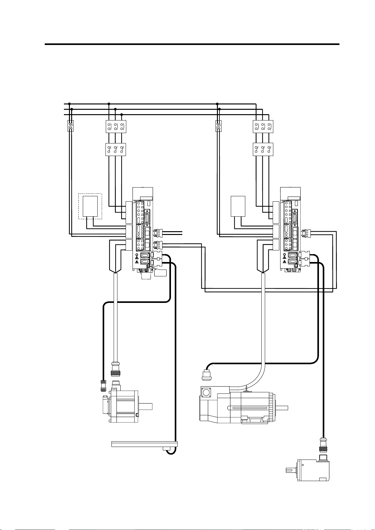
1-1 Servo/spindle drive system configuration
1-1-1 System configuration
3-phase or single-phase
AC200 to 230V
L1
L2
L3
Breaker
or
fuse
(Note)
Prepared
by user
NFB
(Note)
Prepared by user
Contactor
(Note)
Prepared by user
Breaker
or
fuse
(Note)
Prepared
by user
NFB
(Note)
Prepared by user
Contactor
(Note)
Prepared by user
L11
L21
Option
Regene-
rative
resistor
L1 L2 L3
V
U
(MDS-D-SVJ3)
CNP1 CNP2
P
C
CNP3
W
Servo
drive unit
BAT
CN1A
CN1B
CN2
From NC
CN3
L11
L21
Regene-
rative
resistor
L1 L2 L3
V
U
(MDS-D-SPJ3)
CNP1 CNP2
P
C
CNP3
W
Spindle
drive unit
CN1A
CN2
CN3
Servomotor Spindle motor
Linear scale ( in full closed control)
(Note)
Prepared by user
1 - 2
Spindle side detector
1. Introduction
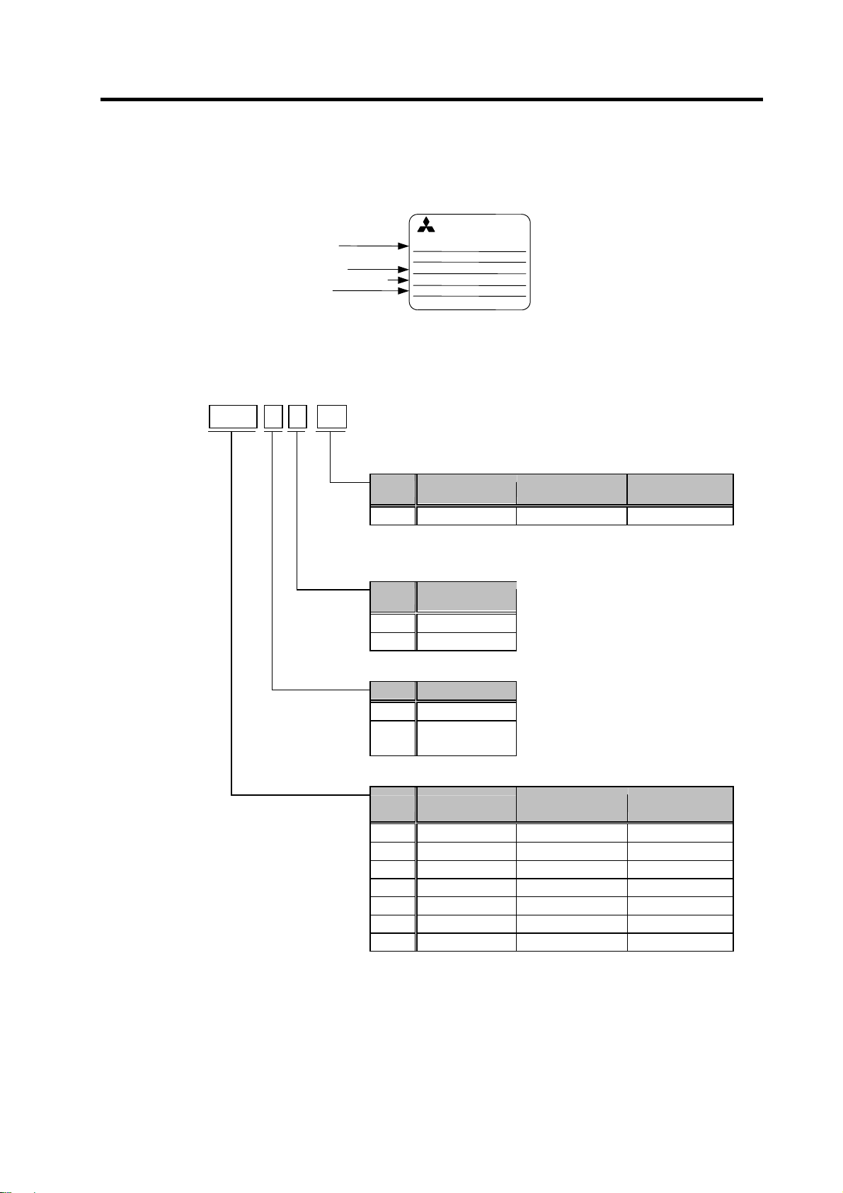
1-2 Explanation of type
1-2-1 Servomotor type
MITSUBISHI
Motor type
Rated output
Rated rotation speed
Serial No.
(1) HF Series
HF
(4) Detector
A48 Absolute position 260,000p/rev OSA18
(3) Shaft end structure
S Straight
T Taper
(2) Magnetic brake
None None
(1) Rated output · Maximum rotation speed
75 0.75 kW 5000 r/min □90 mm
105 1.0 kW 5000 r/min □90 mm
54 0.5 kW 4000 r/min □130 mm
104 1.0 kW 4000 r/min □130 mm
154 1.5 kW 4000 r/min □130 mm
204 2.0 kW 4000 r/min □176 mm
354 3.5 kW 3500 r/min □176 mm
(1) (2) (3) - (4)
Symbol
Symbol
Symbol
Symbol Rated output
AC SERVO MOTOR
HFxxxBS
INPUT 3AC 155 V xxx A
OUTPUT x.xkW IEC34-1 1994
3000r/min IP65 CI.F xx kg
SER.No.
xxxxxxxx*
MITSUBISHI ELECTRIC
MADE IN JAPAN 00395298-01
Motor rating nameplate
Detection
method
Shaft end
structure
Magnetic brake
B
With magnetic
brakes
DATE
04-1
(Note)
"Taper" is available for the motor whose
flange size is □90mm or □130mm.
Maximum rotation
Resolution Detector type
speed
Flange size
1 - 3
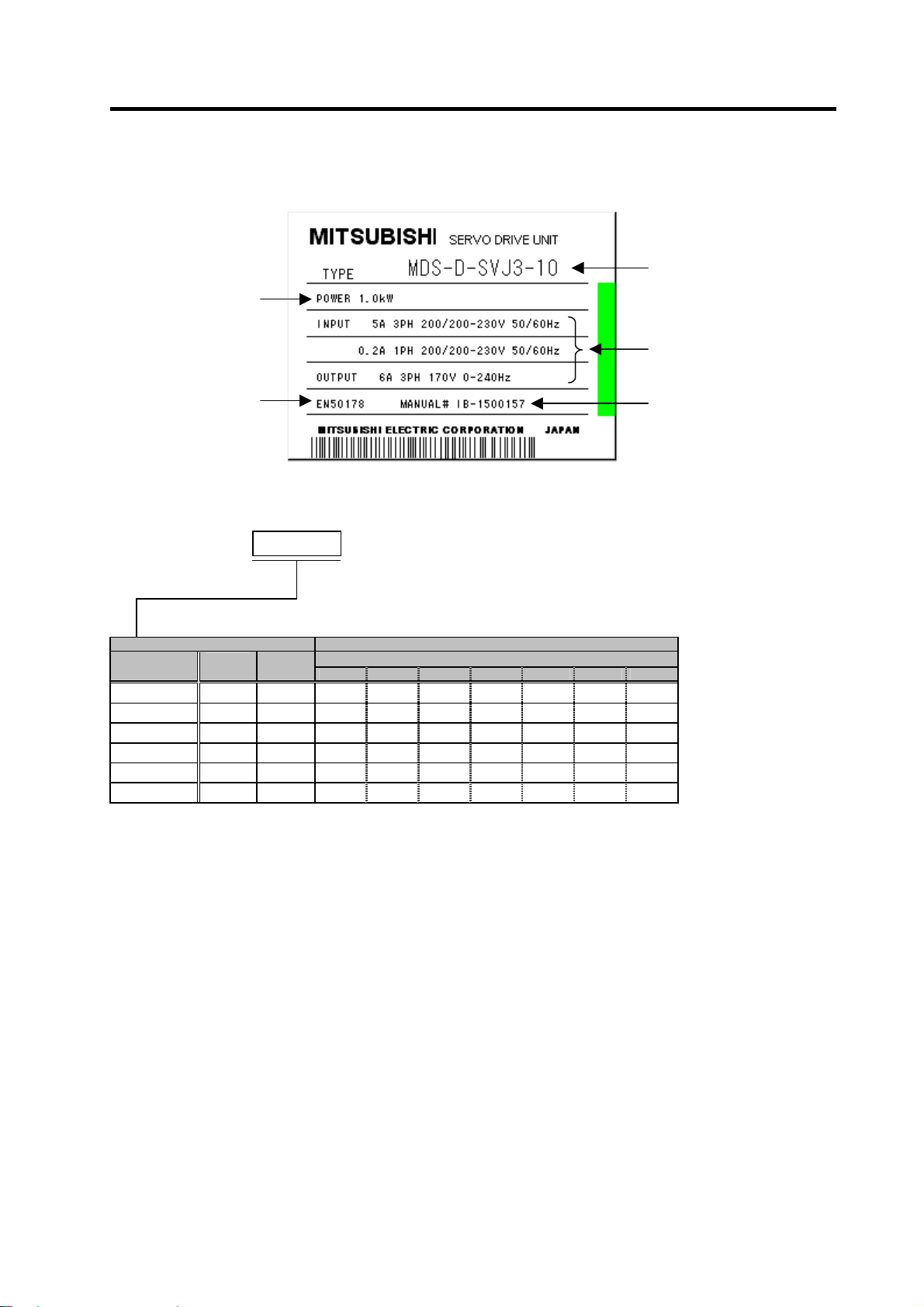
1-2-2 Servo drive unit type
Output
1. Introduction
Type
Input/output conditions
Applicable standard
Rating nameplate
MDS-D-SVJ3 (1)
(1) Type
MDS-D-SVJ3-
§ Indicates the compatible motor for each servo drive unit.
Srvo drive unit Compatible motor
Rated
output
03 0.3kW 40mm
04 0.4kW 40mm
07 0.7kW 60mm § § §
10 1.0kW 90mm §
20 2.0kW 90mm § §
35 3.5kW 90mm §
Unit width
75 105 54 104 154 204 354
HF□
Manual No.
1 - 4
1. Introduction
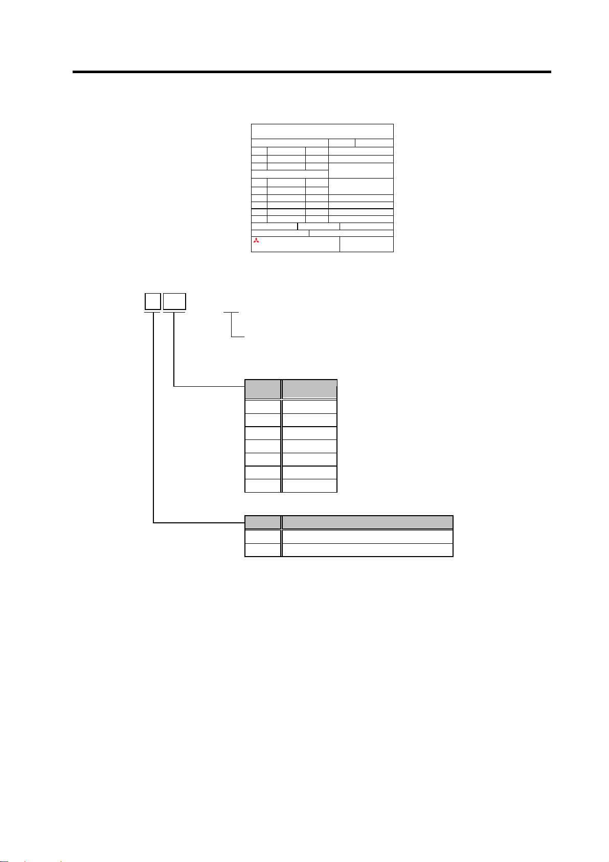
1-2-3 Spindle motor type
SJ-
(2) Short time rated output
0.75 0.75kW
1.5 1.5kW
2.2 2.2 kW
3.7 3.7 kW
5.5 5.5 kW
7.5 7.5 kW
11 11 kW
(1) Motor series
VL Motor with fan (0.75kW, 1.5kW)
V Motor with fan (2.2kW to 11kW)
(1) (2)
-
01
MITSUBISHI AC SPINDLE MOTOR
TYPE
SJ–V5. 5–01E
SI CONT 4 POLE
kW r/min
3.7 1500-6000 25 P OW ER FA CT OR 8 2 %
2.8 8000 17
S2 30 min S3 50 %
kW r/min
5.5 1500-6000 33
4.1 8000 23 INSUL ATION CLASS F
AMB TEMP. 0-40°C
SERIAL
DATE
FRAME D90F WEIGHT 49 kg IP 44
IEC 34-1 1994 SPEC No.RSV00023*
MITSUBISHI ELECTRIC CORPORATION
A(~)
WIND CONNECT
max
MOTOR INPUT(~)
137 - 16 2 V
A(~)
AMP INPUT(~)
max
200-230V 50/60Hz
MADE IN JAPAN
A19103-01
3 PHASES
U
995291-01
Rating nameplate
E
Motor for MDS-D-SPJ3 of MDS-D-SVJ3/SPJ3 series
Symbol
Short time
rated output
Symbol Motor series
(Note) The built-in spindle motor is available by special order.
1 - 5
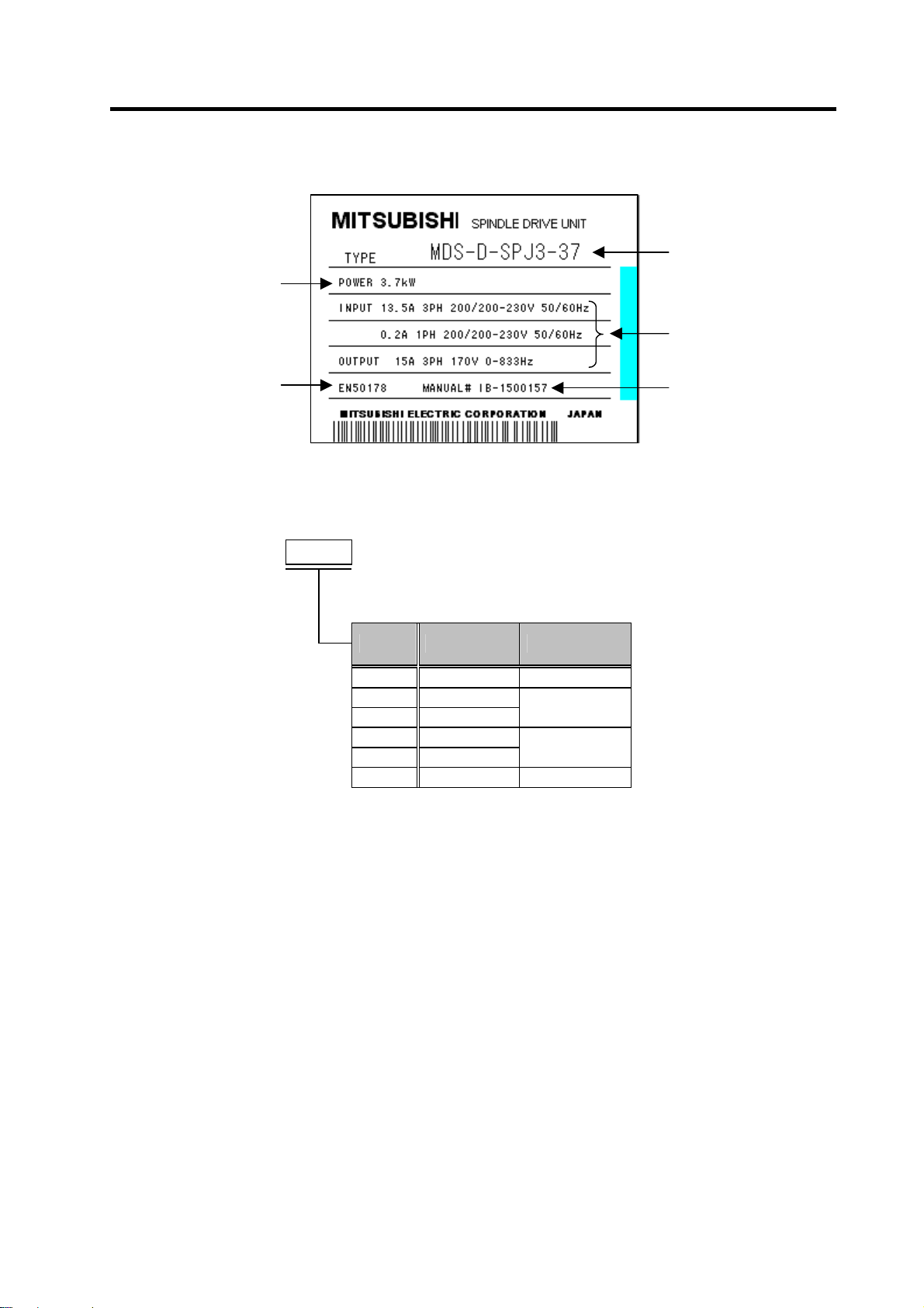
1-2-4 Spindle drive unit type
Output
1. Introduction
Type
Input/output
conditions
Applicable standard
Rating nameplate
Manual No.
MDS-D-SPJ3
(1) Capacity
075 0.75kW 60mm wide
22 2.2kW
37 3.7kW
55 5.5kW
75 7.5kW
110 11.0kW 172mm wide
(1)
-
Symbol Rated output Unit width
90mm wide
130mm wide
1 - 6

2. Specifications
2-1 Servomotor.........................................................................................................................................2-2
2-1-1 Specifications list.........................................................................................................................2-2
2-1-2 Torque characteristics.................................................................................................................2-3
2-2 Spindle motor.....................................................................................................................................2-4
2-2-1 Specifications .............................................................................................................................. 2-4
2-2-2 Output characteristics.................................................................................................................. 2-5
2-3 Drive unit............................................................................................................................................2-6
2-3-1 Installation environment conditions............................................................................................. 2-6
2-3-2 Servo drive unit ...........................................................................................................................2-6
2-3-3 Spindle drive unit.........................................................................................................................2-7
2-3-4 D/A output specifications for servo drive unit..............................................................................2-8
2-3-5 D/A output specifications for spindle drive unit .........................................................................2-11
2-3-6 Explanation of each part............................................................................................................2-14
2 - 1

2. Specifications
2-1 Servomotor
2-1-1 Specifications list
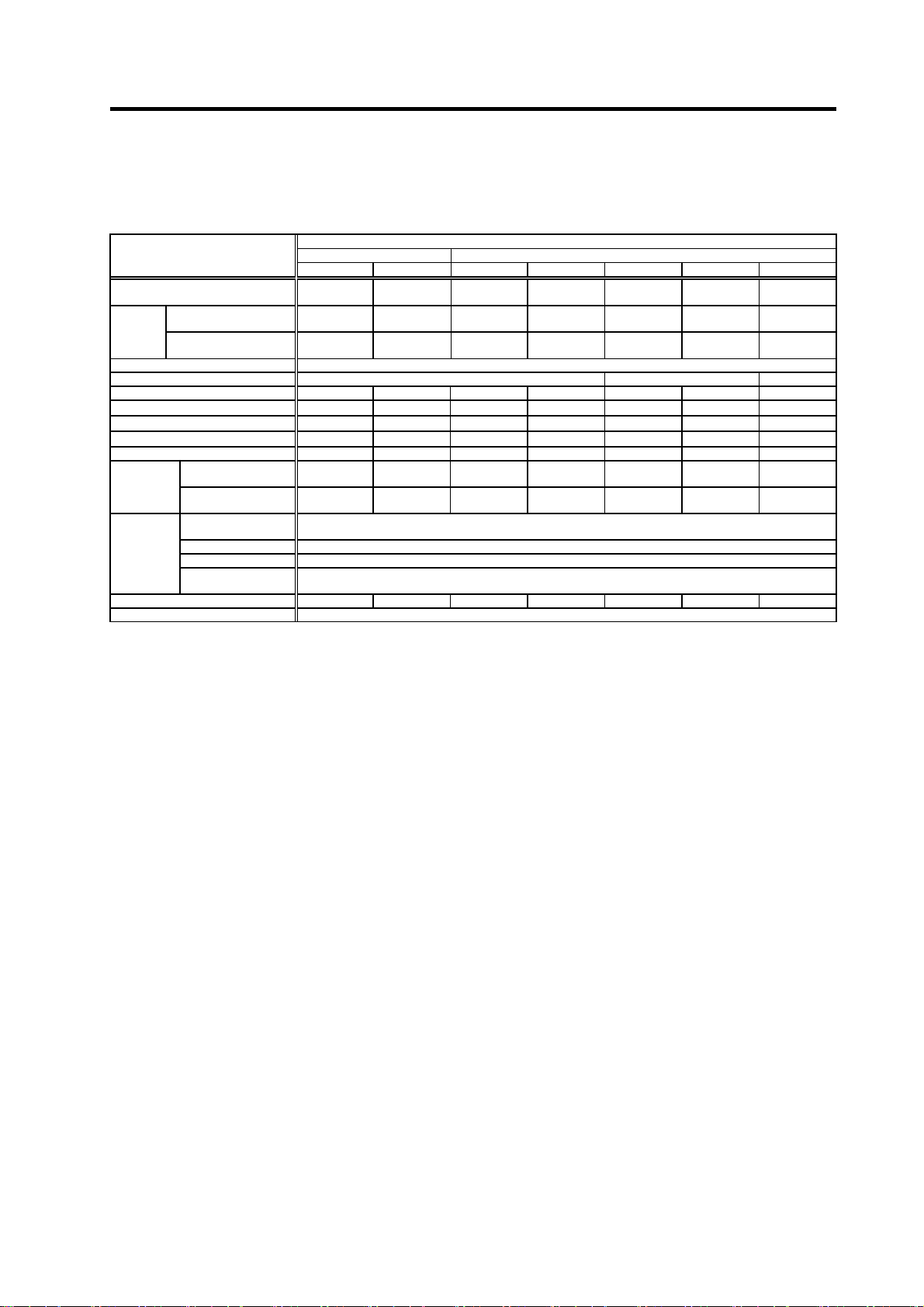
HF Series
Servomotor type
HF75 HF105 HF54 HF104 HF154 HF204 HF354
Compatible servo drive
unit type
Rated output [kW] 0.75 1.0 0.5 1.0 1.5 2.0 3.5
Continuous
characteristics
Rated rotation speed [r/min] 4000 3000
Maximum rotation speed [r/min] 5000 4000 3500
Maximum current [A] 14.0 15.5 16.8 29.0 52.0 52.0 64.0
Maximum torque [N·m] 8.0 11.0 13.0 23.3 42.0 42.0 65.0
Power rate at continuous
rated torque
Motor inertia [kg·cm2] 2.6 5.1 6.1 11.9 17.8 38.3 75.0
Motor inertia with brake [kg·cm2] 2.8 5.3 8.3 14.1 20.0 48.0 84.7
Maximum motor shaft conversion load
inertia ratio
Motor side detector
Structure
Environment
Weight
Without / with brake
Armature insulation class Class F
(Note 1) The above characteristics values are representative values. The maximum current and maximum torque are the values
(Note 2) Use the HF motor in combination with the MDS-D-SVJ3 Series drive unit compatible with the 200VAC input.
(Note 3) The shaft-through portion is excluded.
Rated
current
Rated torque [N·m] 1.8 2.4 1.6 3.2 4.8 6.4 11.1
Stall current [A] 3.2 4.6 3.2 6.6 11.0 14.6 22.0
Stall torque [N·m] 2.0 3.0 2.9 5.9 9.0 13.7 22.5
Ambient temperature
Ambient humidity
Atmosphere
Altitude
Vibration X:19.6m/s
when combined with the drive unit.
This motor is not compatible with the conventional MDS-B/C1/CH Series.
MDS-D-SVJ3- 07 07 07 10 20 20 35
[A] 2.8 3.6 1.8 3.6 5.8 6.8 13.8
[kW/s] 12.3 11.2 4.1 8.4 12.7 10.6 16.5
High-speed, high-accuracy machine : 3 times or less of motor inertia
General machine tool (interpolation axis) : 5 times or less of motor inertia
General machine (non-interpolation axis) : 7 times or less of motor inertia
Fully closed, self-cooling (Protection method: IP67) (Note3)
Operation: 80%RH or less (with no dew condensation),
Storage: 90%RH or less (with no dew condensation)
Indoors (no direct sunlight); no corrosive gas, inflammable gas, oil mist, or dust
[kg]
2.5/
3.9
4.3/
ABS specifications: HF□-A48
Resolution per motor revolution
A48:260,000pulse/rev
Operation: 0 to 40°C (with no freezing),
Storage: -15°C to 70°C (with no freezing)
Operation: 1000 meters or less above sea level,
Storage: 10000 meters or less above sea level
5.7
2
(2G) Y:19.6m/s2(2G)
4.8/
6.8
6.5/
8.5
8.3/
10.3
12.0/
18.0
19.0/
25.0
2 - 2

C
f
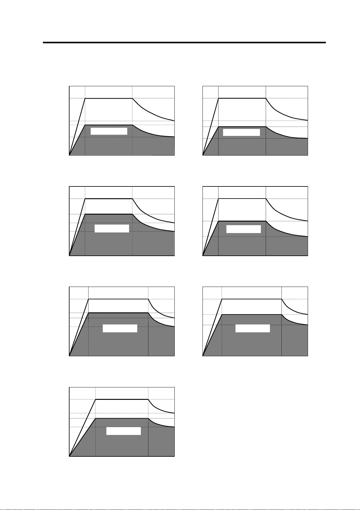
2-1-2 Torque characteristics
(1) HF Series
10
[ HF75 ]
2. Specifications
[ HF105 ]
12
7.5
m]
.
Short time operation range
5
Torque [N
2.5
Continuous operation range
0
0 2000 5000
Rotation speed [r/min]
4000 4000
[ HF54 ]
15
12
m]
.
9
Short time operation range
Torque [N
3
Continuous
operation range
0
0 2000 4000
Rotation speed [r/min]
9
m]
.
Torque [N
Short time operation range
6
3
Continuous operation range
0
0 2000 5000
Rotation speed [r/min]
[ HF104 ]
25
20
m]
.
15
Short time operation range
10 206
Torque [N
5
Continuous
operation range
0
0 2000 4000
Rotation speed [r/min]
50
[ HF154 ]
40
m]
.
30
Short time operation range
Torque [N
10
ontinuous
operation range
0
0 2000 4000
Rotation speed [r/min]
[ HF204 ]
50
40
m]
.
30
Short time operation range
20
Torque [N
10
Continuous operation range
0
0 2000 4000
Rotation speed [r/min]
[ HF354 ]
80
60
m]
.
Torque [N
Short time operation range
40
20
Continuous operation range
0
0 1500 3500
Rotation speed [r/min]
3000
The above graphs show the data
(Note)
when applied the input voltage o
200VAC. When the input voltage
is 200VAC or less, the short tim e
operation range is limited.
2 - 3
2. Specifications
2-2 Spindle motor
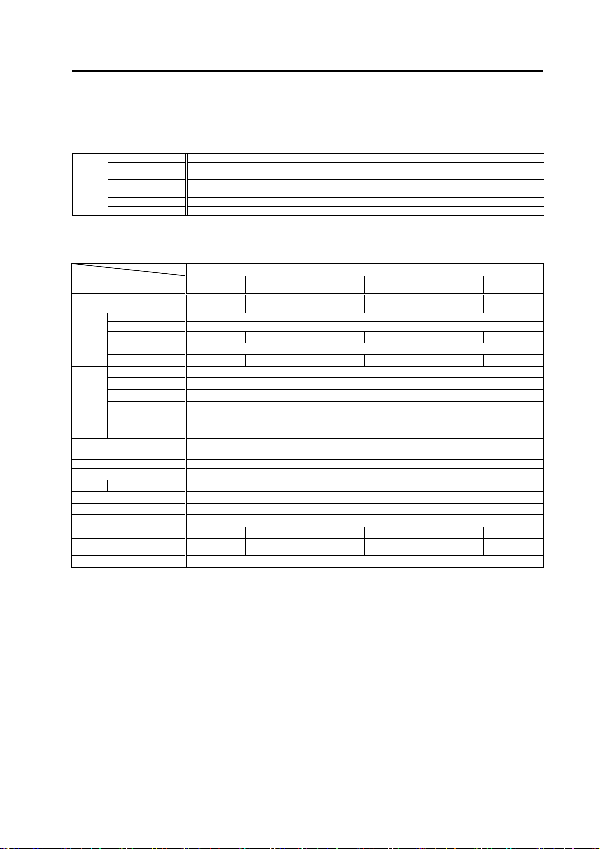
2-2-1 Specifications
Spindle motor type
Compatible spindle drive unit type
MDS-D-SPJ3-
Output
capacity
Base rotation speed [r/min] 1500
Maximum rotation speed [r/min] 10000 8000 6000
Frame No. A71 B71 A90 B90 D90 A112 B112
Continuous rated torque [N・m]
Inertia [kg・cm2]
GD2 [kg・cm2]
Tolerable radial load [N] 490 490 980 980 1470 1960 1960
Cooling fan
Environment
Weight [kg] 15 20 25 30 49 60 70
Insulation Class F
(Note 1)
Continuous rating
[kW]
Short time rated output
[kW]
Input voltage
Maximum power
consumption
Ambient
temperature
Ambient humidity Operation: 90%RH or less (with no dew condensation), Storage: 90%RH or less (with no dew condensation)
Atmosphere Indoors (no direct sunlight); no corrosive gas, inflammable gas, oil mist, or dust
Altitude
The rated output is guaranteed at the rated input voltage (200/220/230VAC) to the drive unit.
If the input voltage fluctuates and drops below 200VAC, the rated output may not be attained.
The 50%ED rating applies for a 10-minute cycle time consisting of ON for five minutes and OFF for five minutes.
(Note 2)
The tolerable radial load is the value calculated at the center of output shaft.
(Note 3)
The protection level is IP44.
(Note 4)
0.75 (10min) 1.5 (10min) 2.2 (15min) 3.7 (15min) 5.5 (30min) 7.5 (30min) 11.0 (30min)
Single-phase
SJ-VL SJ-V
0.75-01E 1.5-01E 2.2-01E 3.7-01E 5.5-01E 7.5-01E 11-01E
075 22 22 37 55 75 110
0.4 0.75 1.5 2.2 3.7 5.5 7.5
2.55 4.77 9.55 14.0 23.5 35.0 47.8
13 24 65 85 137 235 298
53 96 260 340 550 940 1190
200V
14W 14W 42W 42W 42W 40W 40W
Single-phase
200V
Operation: 0 to 40°C (with no freezing), Storage: -20°C to 65°C (with no freezing)
Operation: 1000 meters or less above sea level, Storage: 1000 meters or less above sea level,
Transportation: 10000 meters or less above sea level
Motor with fan SJ Serise
Single-phase
200V
Single-phase
200V
Single-phase
200V
3-phase
200V
3-phase
200V
2 - 4
O
t
t
[
kW
]
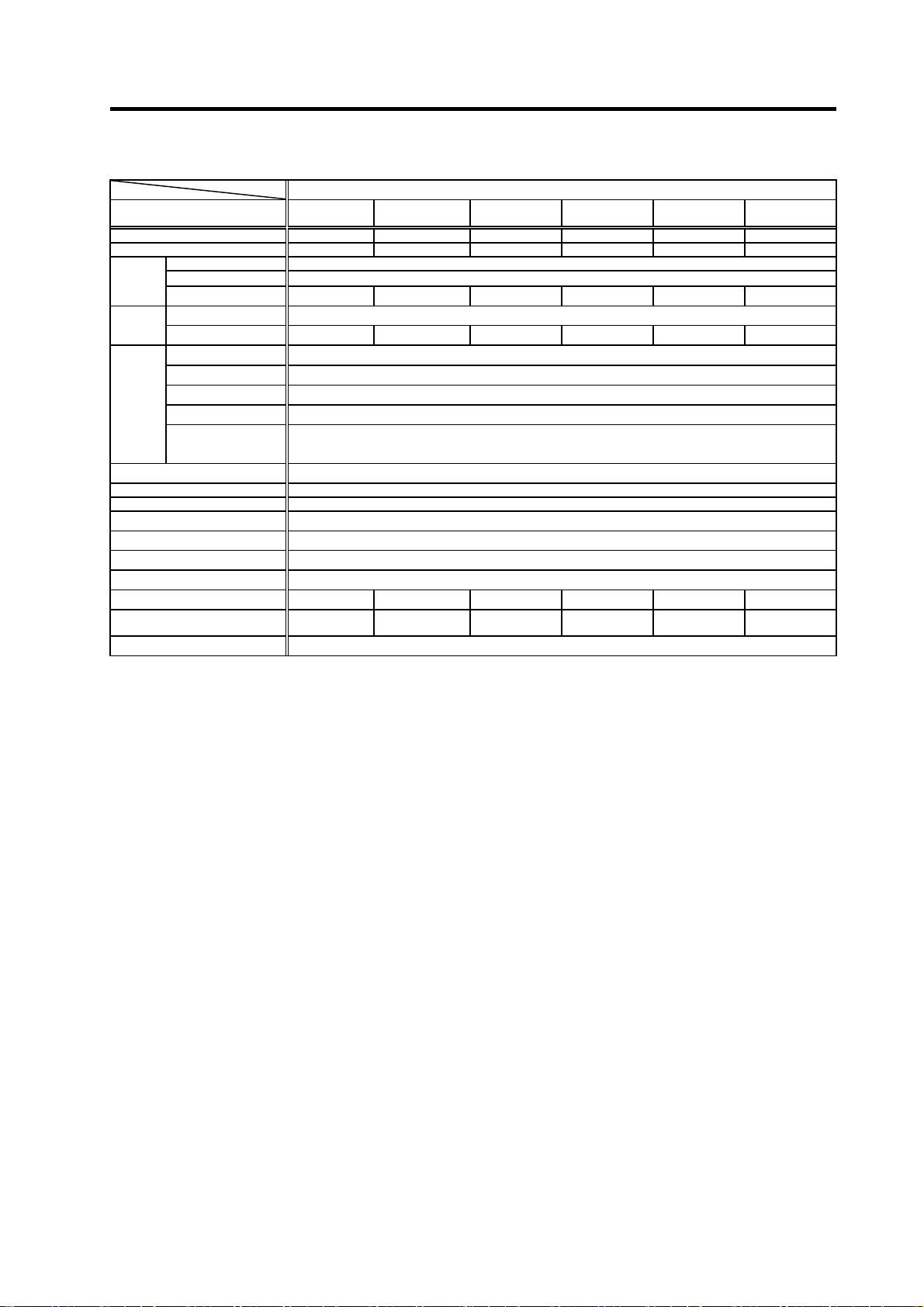
2-2-2 Output characteristics
[ Motor with fan series SJ-VL0.75-01E ] [ Motor with fan series SJ-VL1.5-01E ]
2. Specifications
0.75
0.45
pu
0.4
u
0.24
0
0 1500 6000
15-minute rating
Continuous rating
Rotation speed [r/min]
[ Motor with fan series SJ-V2.2-01E] [ Motor with fan series SJ-V3.7-01E]
2.2
15-minute rating
1.5
1.3
0.9
Output [kW]
0
0 1500 6000
Continuous rating
Rotation speed [r/min]
1.5
15-minute rating
0.9
0.75
Output [kW]
0.45
10000 0 1500 6000
0
Continuous rating
Rotation speed [r/min]
3.7
15-minute rating
2.2
Output [kW]
1.3
10000 0 1500 6000
0
Continuous rating
Rotation speed [r/min]
10000
10000
[ Motor with fan series SJ-V5.5-01E] [ Motor with fan series SJ-V7.5-01E]
5.5
15-minute rating
4.1
3.7
2.8
Output [kW]
0
0 1500 6000
Continuous rating
Rotation speed [r/min]
[ Motor with fan series SJ-V11-01E]
11
8.3
7.5
5.6
Output [kW]
15-minute rating
Continuous rating
7.5
15-minute rating
5.5
4.1
Output [kW]
8000 0 1500 6000
0
Continuous rating
Rotation speed [r/min]
8000
0
0 1500 4500
6000
Rotation speed [r/min]
2 - 5
2. Specifications
2-3 Drive unit
2-3-1 Installation environment conditions
Common installation environment conditions for servo and spindle are shown below.
Environment
2-3-2 Servo drive unit
Servo drive
unit type
Rated output [kW] 0.3 0.4 0.7 1.0 2.0 3.5
Power facility capacity [kVA] 0.5 1.0 1.3 1.7 3.5 5.5
Input
Output
Control
power
Earth leakage current [mA] 1 (Max. 2)
Main circuit method
Control method
Braking
External analog output
Structure
Cooling method
Weight
Heat radiated at rated
output
Noise
Ambient temperature Operation: 0 to 55°C (with no freezing), Storage / Transportation: -15°C to 70°C (with no freezing)
Ambient humidity
Atmosphere
Altitude Operation/Storage: 1000 meters or less above sea level, Transportation: 13000 meters or less above sea level
Vibration/impact 4.9m/s
With no corrosive gas, inflammable gas, oil mist, dust or conductive fine particles
MDS-D-SVJ3- 03 04 07 10 20 35
Rated voltage [V] 200AC (50Hz) /200 to 230AC (60Hz)
Frequency [Hz] 50/60 Frequency fluctuation within ±5%
Rated current [A] 1.5 2.9 3.8 5.0 10.5 16.0
Rated voltage [V] AC155
Rated current [A] 1.5 3.2 5.8 6.0 11.0 17.0
Voltage
Frequency [Hz] 50/60 Frequency fluctuation within ±5%
Current
Rush current [A] Max.30
Rush
conductivity
time
Dynamic brakes Built-in
[V] 200AC (50Hz) /200 to 230AC (60Hz)
[A] Max.0.2
[ms] Max.6
Protection type (Protection method: IP20 [over all] / IP00 [Terminal block TE1])
[kg] 0.8 1.0 1.4 2.3 2.3 2.3
[W] 25 35 50 90 130 195
Self-cooling Forced wind cooling
Operation: 90%RH or less (with no dew condensation)
Storage / Transportation: 90%RH or less (with no dew condensation)
Indoors (no direct sunlight)
2
(0.5G) / 49m/s2 (5G)
Servo drive unit MDS-D-SVJ3 Series
Power fluctuation rate within +10%, -15%
Power fluctuation rate within +10%, -15%
Converter with resistor regeneration circuit
Sine wave PWM control method
Regenerative braking and dynamic brakes
0 to +5V, 2ch (data for various adjustments)
Less than 55dB
2 - 6
2-3-3 Spindle drive unit
Spindle drive
unit type
Rated output
Power facility capacity
Input
Output
Control
power
Earth leakage current
Main circuit method
Control method
Braking
External analog output
Structure
Cooling method
Weight
Heat radiated at
continuous rated output
Noise
MDS-D-SPJ3- 075 22 37 55 75 110
Rated voltage [V] 200AC (50Hz) / 200 to 230AC (60Hz) Power fluctuation rate within +10%, -15%
Frequency
Rated current [A] 2.6 9.0 10.5 16.0 26.0 35.4
Rated voltage [V] 270 to 311DC
Rated current [A] 4.5 10.0 11.0 18.0 26.0 36.0
Voltage
Frequency
Current
Rush current [A] Max.30
Rush
conductivity
time
[kW] 0.75 2.2 3.7 5.5 7.5 11.0
[kVA] 2.0 4.0 7.0 9.0 12.0 17.0
[Hz] 50/60
[V] 200AC (50Hz) / 200 to 230AC (60Hz) Power fluctuation rate within +10%, -15%
[Hz] 50/60
[A] Max.0.2
[ms] Max.6
[mA] 6 (Max. 15)
[kg] 1.4 2.1 2.1 4.6 4.6 6.5
[W] 50 90 130 150 200 300
2. Specifications
Spindle drive unit MDS-D-SPJ3 Series
Frequency fluctuation within: ±5%
Frequency fluctuation within: ±5%
Converter with resistor regeneration circuit
Sine wave PWM control method
Regenerative braking
0 to +5V, 2ch (data for various adjustments)
Protection type (Protection method: IP20 [over all] / IP00 [Terminal block TE1])
Forced wind cooling
Less than 55dB
2 - 7
2. Specifications
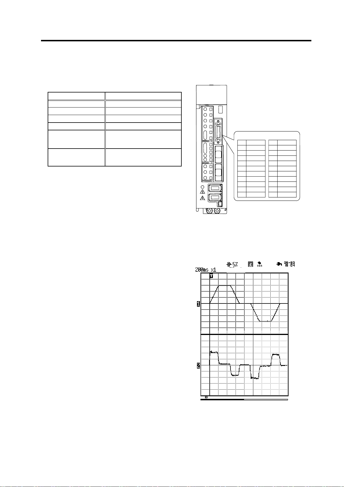
2-3-4 D/A output specifications for servo drive unit
(1) D/A output specifications
Item Explanation
2ch
Output cycle
Output precision
Output voltage range
Output magnification
setting
Output pin
(CN9 connector)
0.8ms (min. value)
10bit
0V to 2.5V (zero) to +5V
-32768% to +32767% (1% scale)
MO1 = Pin 4
MO2 = Pin 14
GND = Pins 1, 11
CN9 connector
Pin
1
2
3
4
5
6
7
8
10
Name
LG
MO1
9
Pin
11
12
13
14
15
16
17
18
19
20
Name
LG
MO2
MDS-D-SVJ3
When the output data is 0, the offset voltage is 2.5V.
If there is an offset voltage, adjust the zero level position in the measuring instrument side.
Memory
+5 [V]
Speed FB
+2.5 [V]
0 [V]
+5 [V]
Current FB
+2.5 [V]
Scroll
2 - 8
0 [V]
Example of D/A output waveform
Loading...