


CEILING CASSETTE TYPE AIR CONDITIONERS
MLZ-KP09NA MLZ-KP12NA MLZ-KP18NA
INstALLAtIoN MANuAL |
For INSTALLER |
•This manual only describes the installation of indoor unit.
When installing the outdoor unit, refer to the installation manual of outdoor unit.
MANuAL DE INstALACIÓN |
PARA EL INSTALADOR |
•En este manual sólo se describe la instalación de la unidad interior.
Para instalar la unidad exterior, consulte el manual de instalación de dicha unidad.
NotICE D’INstALLAtIoN |
POUR L’INSTALLATEUR |
•Cette notice ne décrit que l’installation de l’unité interne.
Pour l’installation de l’unité externe, se reporter à la notice d’installation de l’appareil.
English
Español
Français
ENGLISH
|
CoNtENts |
|
1. |
BEFORE INSTALLATION............................ |
1 |
2. |
INDOOR UNIT INSTALLATION................... |
4 |
3. |
FLARING WORK AND PIPE |
|
|
CONNECTION ............................................ |
8 |
4. |
TEST RUN................................................. |
10 |
5. |
GRILLE (OPTION) INSTALLATION .......... |
10 |
6. |
PUMPING DOWN ..................................... |
11 |
7. |
CONNECTING AN INTERFACE (OPTION) |
|
|
TO THE AIR CONDITIONER .................... |
11 |
This installation manual describes only for the indoor unit. Refer to the MXZ type manual for outdoor unit set up.
Required tools for Installation
Phillips screwdriver |
Flare tool for R410A |
Level |
Gauge manifold for R410A |
Scale |
Vacuum pump for R410A |
Utility knife or scissors |
Charge hose for R410A |
2-15/16 in. (75 mm) hole saw |
Pipe cutter with reamer |
Torque wrench |
Water bottle |
Wrench (or spanner) |
0.9 to 1.0 L water |
1. BEFoRE INstALLAtIoN
1-1. tHE FoLLoWING sHouLD ALWAYs BE oBsERVED FoR sAFEtY
•Be sure to read “THE FOLLOWING SHOULD ALWAYS BE OBSERVED FOR SAFETY” before installing the air conditioner.
•Be sure to observe the warnings and cautions specified here as they include important items related to safety.
•After reading this manual, be sure to keep it together with the OPERATING INSTRUCTIONS for future reference.
•Please report to your supply authority or obtain their consent before connecting this equipment to the power supply system.
■Do not install the unit by yourself (user).
Incomplete installation could cause fire or electric shock, injury due to the unit falling, or leakage of water. Consult the dealer from whom you purchased the unit or a qualified installer.
■Perform the installation securely referring to the installation manual.
Incomplete installation could cause fire or electric shock, injury due to the unit falling, or leakage of water.
■When installing the unit, use appropriate protective equipment and tools for safety.
Failure to do so could cause injury.
■Install the unit securely in a place which can bear the weight of the unit.
If the installation location cannot bear the weight of the unit, the unit could fall causing injury.
■Electrical work should be performed by a qualified, experienced electrician, according to the installation manual. Be sure to use an exclusive circuit. Do not connect other electrical appliances to the circuit.
If the capacity of the power circuit is insufficient or there is incomplete electrical work, it could result in a fire or an electric shock.
■Ground the unit correctly.
Do not connect the ground to a gas pipe, water pipe, lightning rod or telephone ground. Defective grounding could cause electric shock.
■Do not damage the wires by applying excessive pressure with parts or screws.
Damagedwirescouldcausefire orelectricshock.
■Be sure to cut off the main power in case of setting up the indoor P.C. board or wiring works.
Failure to do so could cause electric shock.
■Use the specified wires to connect the indoor and outdoor units securely and attach the wires firmly to the terminal block connecting sections so the stress of the wires is not applied to the sections. Do not extend the wires, or use intermediate connection.
Incomplete connecting and securing could cause fire.
■Do not install the unit in a place where inflammable gas may leak.
If gas leaks and accumulates in the area around the unit, it could cause an explosion.
■Do not use intermediate connection of the power cord or the extension cord and do not connect many devices to one AC outlet.
It could cause a fire or an electric shock due to defectivecontact,defective insulation,exceeding the permissible current, etc.
■Depending on the installation area, install a Ground Fault Interrupt (GFI) circuit breaker.
If the Ground Fault Interrupt (GFI) circuit breaker is not installed, an electric shock could occur.
■Perform the drainage/piping work securely according to the installation manual.
If there is defect in the drainage/piping work, water could drip from the unit, and damage household items.
 WARNING (Could lead to death, serious injury, etc.)
■Be sure to use the parts provided or specified parts for the installation work.
The use of defective parts could cause an injury or leakage of water due to a fire, an electric shock, the unit falling, etc.
■When plugging the power supply plug into the outlet, make sure that there is no dust, clogging, or loose parts in both the outlet and the plug. Make sure that the power supply plug is pushed completely into the outlet.
If there is dust, clogging, or loose parts on the power supply plug or the outlet, it could cause electric shock or fire. If loose parts are found on the power supply plug, replace it.
■Attach the electrical cover to the indoor unit and the service panel to the outdoor unit securely.
If the electrical cover of the indoor unit and/or the service panel of the outdoor unit are not attached securely, it could result in a fire or an electric shock due to dust, water, etc.
■When installing, relocating, or servicing the unit, make sure that no substance other than the specified refrigerant (R410A) enters the refrigerant circuit.
Any presence of foreign substance such as air cancauseabnormalpressureriseandmayresult in explosion or injury. The use of any refrigerant other than that specified for the system will cause mechanical failure, system malfunction, or unit breakdown. In the worst case, this could lead to a serious impediment to securing product safety.
■Do not discharge the refrigerant into the atmosphere. Check that the refrigerant gas does not leak after installation has been completed. If refrigerant leaks during installation, ventilate the room.
If refrigerant comes in contact with a fire, harmful gas could be generated.
If refrigerant gas leaks indoors, and comes into contact with the flame of a fan heater, space heater, stove, etc., harmful gases will be generated.
■use appropriate tools and piping materials for installation.
The pressure of R410A is 1.6 times more than R22. Not using appropriate tools or materials and incomplete installation could cause the pipes to burst or injury.
■When pumping down the refrigerant, stop the compressor before disconnecting the refrigerant pipes.
If the refrigerant pipes are disconnected while the compressor is running and the stop valve is open, air could be drawn in and the pressure in the refrigeration cycle could become abnormally high. This could cause the pipes to burst or injury.
■When installing the unit, securely connect the refrigerant pipes before starting the compressor.
If the compressor is started before the refrigerant pipes are connected and when the stop valve is open, air could be drawn in and the pressure in the refrigeration cycle could become abnormally high. This could cause the pipes to burst or injury.
■Fasten a flare nut with a torque wrench as specified in this manual.
If fastened too tight, a flare nut may break after a long period and cause refrigerant leakage.
■the unit shall be installed in accordance with national wiring regulations.
■Do not use means to accelerate the defrosting process or to clean, other than those recommended by the manufacturer.
■the appliance shall be stored in a room without continuously operating ignition sources (for example: open flames, an operating gas appliance or an operating electric heater).
■Do not pierce or burn.
■Be aware that refrigerants may not contain an odour.
■Pipe-work shall be protected from physical damage.
■the installation of pipe-work shall be kept to a minimum.
■Keep any required ventilation openings clear of obstruction.
■Keep gas-burning appliances, electric heaters, and other fire sources (ignition sources) away from the location where installation, repair, and other air conditioner work will be performed.
 CAUTION (Could lead to serious injury in particular environments when operated incorrectly.)
■ Do not touch the air inlet or the aluminum |
■ Do not install the outdoor unit where small |
fins of the outdoor unit. |
animals may live. |
This could cause injury. |
If small animals enter the unit and damage its |
|
electrical parts, it could cause a malfunction, |
|
smoke emission, or fire. Keep the area around |
|
the unit clean. |
En-1
Connecting wires and the ground wire
•Use solid conductor Min. AWG14 or stranded conductor Min. AWG14.
•Use double insulated copper wire with 600 V insulation.
•Use copper conductors only. * Follow local electrical codes.
Note:
When the indoor unit is powered from the outdoor unit, depending on local code, a disconnect switch needs to be installed to a power supply circuit.
1-3-2. REFRIGERANt PIPEs
• To prevent condensation, insulate the two refrigerant pipes.
 CAutIoN
Be sure to use the insulation of specified thickness (table on the right). Excessive insulation may cause incorrect installation of the indoor unit, and too little insulation may cause condensate to form.
•The unit has flared connections on both indoor and outdoor sides.
•Remove the valve cover from the outdoor unit, then connect the pipe.
•Refrigerant pipes are used to connect the indoor and outdoor units.
•Be careful not to crush or over bend the pipe in pipe bending.
INDOOR UNIT
Power supply (V, PHASE, Hz) |
208/230, 1, 60 |
|
Min. Circuit Ampacity |
(A) |
1.0 |
Fan motor (F.L.A.) |
(A) |
0.68 |
|
|
Outside |
Minimum |
Insulation |
|
|
Pipe |
wall thick- |
Insulation |
||
|
diameter |
ness |
thickness |
material |
|
|
|
|
|
||
|
|
|
inch (mm) |
|
|
For liquid |
MLZ- |
1/4 (6.35) |
0.0315 |
5/16 (8) |
Heat resist- |
KP09/12/18NA |
(0.8) |
||||
|
|
|
|
|
ant foam |
|
|
|
0.0315 |
|
|
|
MLZ-KP09/12NA |
3/8 (9.52) |
5/16 (8) |
plastic 0.045 |
|
|
(0.8) |
||||
For gas |
|
|
|
Specific |
|
|
|
0.0315 |
|
||
|
MLZ-KP18NA |
1/2 (12.7) |
5/16 (8) |
gravity |
|
|
|
|
(0.8) |
|
|
En-2
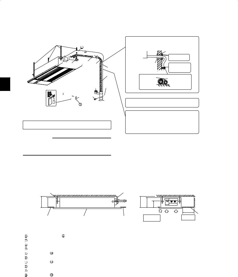
1-4. INSTALLATION DIAGRAM
E
 L
L

 K A
K A
B
J H
P M


 N
N 

Units should be installed by licensed contractor according to local code requirements.
IMPoRtANt NotEs
Check that cabling will not be subject to wear, corrosion, excessive pressure, vibration, sharp edges or any other adverse environmental effects. The check shall also take into account the effects of aging or continual vibration from sources such as compressors or fans.
Be sure to use wall hole sleeve K to prevent indoor/outdoor connecting wire D from contacting metal parts in the wall and to prevent damage by rodents in case the wall is hollow.
|
Wall hole cover L |
|
Indoor unit |
Seal the wall hole |
|
|
||
|
gap with putty L. |
|
Wall hole |
Fix the pipe to wall |
|
sleeve K |
||
|
with pipe fixing |
|
|
band M. |
|
Cut off the |
Pipe fixing band M |
|
extra length. |
||
|
||
|
Fixing screw N |
After the leak test, apply insulating material tightly so that there is no gap.
When the piping is to be attached to a wall containing metals (tin plated) or metal netting, use a chemically treated wooden piece 13/16 in. (20 mm) or thicker between the wall and the piping or wrap 7 to 8 turns of insulation vinyl tape around the piping.
To use existing piping, perform COOLoperation for 30 minutes and pump down before removing the old air conditioner. Remake flare according to the dimension for new refrigerant.
service space
•The dimensions of ceiling opening can be regulated within the range shown in following diagram; so center the main unit against the opening of ceiling, ensuring that the respective opposite sides on all sides of the clearance between them becomes identical.
E E
inch (mm)
(190) |
|
(190) |
|
|
5/16- |
more |
5/16- |
13/16 |
|
more |
1/2 |
|||
1/2 or |
(185) |
or |
(185) |
(122)- |
7- |
7 |
7- |
7 |
4 |
|
|
|
Air outlet |
Air inlet |
Ceiling surface |
|
|
|
|
|
|||
Ceiling surface |
Grille |
Ceiling surface |
Where airflow |
7-7/8 (200) |
||
|
||||||
|
|
|
is not blocked. |
|
or more |
|
|
|
|
|
|
ACCEssoRIEs
Check the following parts before installation.
|
Alkaline battery (AAA) for |
2 |
|
|
Drain hose (with insulation) |
1 |
|
|
Special washer (with cushion, 4 pcs) |
8 |
|
|
Installation template |
1 |
|
|
Fixing screw for |
M5 × 30 mm |
4 |
|
Band |
|
1 |
|
Fixing screw for |
4 × 16 mm |
2 |
|
Remote controller |
|
1 |
|
Remote controller holder |
1 |
|
|
Fixing screw for |
3.5 × 16 mm (Black) |
2 |
PARts to BE PRoVIDED At YouR sItE
A |
Refrigerant pipe |
1 |
B |
Drain pipe (O.D. 1 in. (26 mm)) |
1 |
C |
Installation tools (See 1-3) |
1 |
D |
Indoor/outdoor unit connecting wire* |
1 |
E |
Suspension bolt (W3/8) |
4 |
F |
Nut with flange (W3/8) |
8 |
G |
Nut (W3/8) |
4 |
|
Insulating material for A |
|
H |
(Heat resistant foamed polyethylene, |
1 |
|
specific gravity 0.045, thickness more |
|
|
than 9/16 in. (14 mm)) |
|
|
Insulating material for B |
|
J |
(Foamed polyethylene, specific grav- |
1 |
|
ity 0.03, thickness more than 3/8 in. |
|
|
(10 mm)) |
|
K |
Wall hole sleeve |
1 |
L |
Parts for mending wall hole |
1 |
(putty, cover) |
||
M |
Pipe fixing band |
2 to 7 |
N |
Fixing screw for M |
2 to 7 |
P |
Piping tape |
1 to 5 |
Q |
Protective tape |
1 |
* Note:
Place indoor/outdoor unit connecting wire D at least 3 ft. (1 m) away from the TV antenna wire.
En-3

2. INDooR uNIt INstALLAtIoN
2-1. CEILING oPENINGs AND susPENsIoN BoLt INstALLAtIoN LoCAtIoNs
•Install the indoor unit at least 7 ft. (2.2 m) above floor or grade level. For appliance not accessible to the general public.
•Refrigerant pipes connection shall be accessible for maintenance purposes.
•Make an opening in the ceiling 15-1/8 × 45-11/16 in. (384 mm × 1160
mm)in size. This functions as a check window and will be needed later during servicing.
•If the dimensions are not accurate, when the grille is installed there may be gaps between it and the indoor unit. This may result in dripping water or other problems.
•When deciding on placement, consider carefully the space around the ceiling and make your measurements generous.
•Ceiling types and building construction differ. Therefore you should consult with the builder and decorator.
•Using the installation template  (top of the package) and the gauge (supplied as an accessory with the grille), make an opening in the ceiling so that the main unit can be installed as shown in the diagram. (The method for using the template and the gauge are shown.)
•Use W3/8 suspension bolts E.
•After suspending the indoor unit, you will have to connect the pipes and wiring above the ceiling. Once the location has been fixed and the direction of the pipes has been determined, place the refrigerant and drainage pipes, and the wiring that connects the indoor and outdoor units in their desired locations before suspending the indoor unit. This is especially important in cases where the ceiling is already in existence.
•The packing material (cushion) is taped to the unit. When using the packing material, do not remove it from the unit to prevent horizontal vane damage.
•Remove the packing material (cushion) before installing the plastic bag and the cover.
•To prevent from dust, protect the indoor unit by covering with the plastic bag and the cover.
•Remove the plastic bag and the cover before installing the grille (optional).
•When the distance between joints is 15-1/8 in. (348 mm) or less, please refer to the notice affixed to the packing material.
1)Wooden structures
•Use tie beams (single storied houses) or second floor beams (two story houses) as reinforcing members.
•Wooden beams for suspending air conditioners must be sturdy and their sides must be at least 2-3/8 in. (60 mm) long if the beams are separated by not more than 35-7/16 in. (900 mm) and their sides must be at least 3-9/16 in. (90 mm) long if the beams are separated by as much as 6 ft. (1800 mm).
•Use channel, duct and other parts procured locally to suspend the indoor unit.
2)Ferro-concrete structures
•Secure the suspension bolts using the method shown, or use steel or wooden hangers, etc. to install the suspension bolts E.
•When the unit is put down with its lower surface facing down, place packing material (cushion) underneath to prevent horizontal vane damage.
|
13/16 |
1-1/2 |
Align center of ceiling opening and bolt distance |
unit: inch |
|
|
|
||||
|
|
|
|
||
outlet |
Ceiling |
12-1/8 |
|
|
|
Grille11/16 |
-15 |
|
|
|
|
|
1/8 opening |
|
|
|
|
16- |
|
|
|
|
|
|
13/16 |
-11/2 |
Outlet |
Air |
|
|
outlet |
|
|||
|
|
|
|
||
|
|
|
(underside) |
|
|
|
2-1/8 |
|
41-3/8 |
2-1/8 |
|
|
13/16 |
|
45-11/16 Ceiling opening |
13/16 |
|
|
|
|
|
47-1/4 Grille outlet |
|
20 |
|
38 |
|
Align center of ceiling opening and bolt distance |
unit: mm |
|
|
||||
|
|
|
|||
|
|
|
|
||
|
|
|
|
|
|
|
|
|
|
|
|
424 Grille outlet |
384 Ceiling opening |
308 |
|
|
|
20 |
38 |
Outlet |
Air |
|
outlet |
|||
|
|
|
||
|
|
|
(underside) |
|
54.5 |
1051 |
|
54.5 |
|
20 |
1160 |
Ceiling opening |
20 |
|
|
|
1200 |
Grille outlet |
|
Do not remove.
 Horizontal vane may be damaged.
 Packing material (cushion)
Plastic bag
Cover |
|
12- |
|
|
|
|
|
||
|
|
(308 |
1/8in. |
|
|
|
|
mm) |
C channel |
|
|
|
|
|
|
|
. |
|
|
|
in |
|
|
|
-3/8 |
mm) |
|
|
|
41 |
|
|
|
|
|
|
|
|
|
(1051 |
|
Channel suspension |
||
Roof beam |
|
bracket |
||
|
|
|||
Beam |
|
|
|
Suspension bolt |
Rafter |
|
|
|
|
|
|
|
|
|
Ceiling panel |
|
|
|
|
|
|
|
|
Steel reinforcing rod |
Use inserts rated at 220 to 330 lb (100150 kg) each
Suspension bolts W3/8
En-4
unit suspension procedures
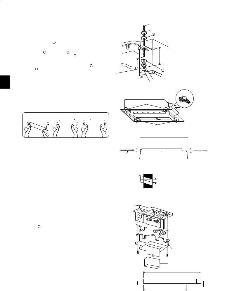
•Adjust the length of the bolt’s protrusion from the ceiling surface beforehand.
•Check the pitch of the suspension bolt E. (12-1/8 × 41-3/8 in. (308 mm × 1051 mm))
1)Install special washer  and their nuts F onto the suspension bolt E in advance.
* Do this in the following order (from the top): nut F, special washer
with cushion , special washer , nut F, nut G. |
|
* Position special washer, with cushion |
with the insulated surface |
pointing down, as in the figure.
2) Lift the unit into place, aligned properly with suspension bolt E. Pass the bracket between special washer, with cushion  and special washer
  , which are already in place, and secure it. Do the same in all four places.
* Make sure the suspension bolt Eextends 2-3/4 in. (70 mm) or more from the surface of the ceiling. Otherwise you will not be able to install the grille (optional).
* If the points for securing the grille are not flush with the ceiling surface, water may condense, or the panel may not open/close.
3) If the long opening in the bracket and opening in the ceiling do not align, adjust them until they do.
4) Check that the four places for securing the grille are all level using a spirit level.
5) Tighten all the nuts.
Secure |
|
|
|
1 Push |
|
2 Secure |
|
|
|
3 Position in the |
|
|
|
||||||||||||||||
|
|
|
|
|
|
|
|
|
|
|
1 |
2 |
|
|
|
|
|
|
|
center |
|
|
|
||||||
|
|
|
|
|
|
|
|
|
|
|
|
|
|
|
|
|
|
|
|
|
|
|
|||||||
|
|
|
|
|
|
|
|
|
|
|
|
|
|
|
|
|
|
|
|
|
|
|
|
|
|
|
|
|
|
|
|
|
|
|
|
|
|
|
|
|
|
|
|
|
|
|
|
|
|
|
|
|
|
|
|
|
|
|
|
2-2. HoLE DRILLING
1)Determine the wall hole position.
2)Drill a dia. 2-15/16 in. (75 mm) hole. The outdoor side should be 3/16 to 1/4 in. (5 to 7 mm) lower than the indoor side.
3)Insert wall hole sleeve K.
|
ESuspension bolt (W3/8) |
|
FNut with flange (W3/8) |
|
Special washer (with cushion, 4 pcs) |
2-3/4 in. (70 mm) or more |
4-13/16 in. (122 mm) |
|
Special washer |
FNut with flange (W3/8)
GNut (W3/8)
Enlarged view
Point for securing grille
|
|
|
|
|
|
|
|
|
|
|
|
Point for securing grille |
|
|
|
|
|
|
|
|
|
||
|
|
|
|
|
|
|
|
|
|
|
|
|
|
|
|
|
|
|
|||||
|
|
|
|
|
|
|
|
|
|
|
|
|
|
|
|
|
|
Make sure these |
|||||
Make sure these |
|
|
|
|
|
|
|
|
surfaces are |
||||||||||||||
surfaces are flush |
|
|
|
|
|
|
|
|
flush with each |
||||||||||||||
with each other (0 to |
|
|
Unit |
|
|
|
other (0 to 1/8 in. |
||||||||||||||||
1/8 in. (0-3 mm)). |
|
|
|
|
|
(0-3 mm)). |
|||||||||||||||||
|
|
|
|
|
|
|
|
|
|
|
|
|
|
|
|
|
|
|
|
|
|
|
|
Ceiling surface |
|
|
|
|
|
|
|
|
|
|
|
|
|
|
|
|
|
|
|||||
|
|
|
|
|
|
Drain pan |
|
|
|
|
|
|
|
|
|
||||||||
|
|
|
|
|
|
|
|
|
|
|
|
|
|
|
|
|
|
|
|
|
|||
|
Point for securing grille |
Point for securing grille |
|||||||||||||||||||||
|
Wall |
ø2-15/16 in. |
3/16 to 1/4 in. |
(ø75 mm) |
|
|
(5-7 mm) |
|
Outdoor side |
2-3. DRAIN PIPING
•Use drain pipe B for drain piping. Be sure to connect the piping joints using adhesive of polyvinyl chloride family to prevent leakage.
•Before drain piping work, remove the pipe cover, hose band, pipe band, and spacer (cushion). Dispose of the spacer (cushion), as it will not be needed.
•Drain hose  is 21-5/8 in. (550 mm) long, so that drain piping exit can be moved up. Cut drain hose
 into appropriate length before connecting.
Hose band
Pipe band
|
Pipe cover |
|
|
Spacer (cushion) |
|
|
21-5/8 in. (550 mm) |
|
Indoor unit side |
16-15/16 in. (430 mm) |
Drain piping side |
|
||
|
Cut within this area |
(Connect drain |
|
pipe B) |
|
|
|
En-5

•Connect drain pipe B directly to drain piping connecting part (socket side) of drain hose .
.
•Be sure to connect drain hose  to the indoor unit side as shown in the illustration on the right. Be sure to connect the drain hose connecting part using adhesive of polyvinyl chloride family to prevent leakage.
•To bring up the drain exit, first arrange drain hose  to go upward vertically, and then provide 1/100 or more downward slope, as shown in the illustration below.
Drain hose |
Drain piping connecting part (with socket) |
Drain hose connecting part |
Drain pipe B |
|
1/100 or more downward slope
2-3/8 in.
(61 mm)
19-11/16 in. (500 mm) or less
Drain piping connecting part |
|
Drain pipe B |
|
Drain pipe B |
|
|
Pipe elbow |
|
|
|
Drain hose |
|
|
Drain hose |
|
Drain hose |
connecting part |
|
1/100 or more |
|
|
downward slope |
* Drain hose |
can be cut by |
|
|
tools such as cutters. |
|
2-3/8 in. |
Ceiling |
|
(61 mm) |
|
|
*Do not make drain piping as shown.
Ceiling
Drain piping connecting part |
|
|
|
|
|
||||
Drain hose |
Insulating material J |
|
|||||||
|
|
|
|
|
|
|
|
|
|
|
|
|
|
|
|
|
|
|
|
|
|
|
|
|
|
|
|
||
|
|
|
|
|
|
||||
Drain piping con- |
|
|
|
|
|
|
|||
|
|
|
|
|
|||||
necting part |
|
|
|
|
|
|
|
||
About 2-3/8 in. (60 |
|
|
|
Drain pipe B |
|
||||
mm) from the end |
|
|
|
|
|||||
|
|
|
|
|
|
|
|
|
|
•Insert the drain pipe B completely into drain piping connecting part.
•Apply insulating material J until drain piping connecting part, as shown above.
• If the drain piping pass indoor, be sure to apply insulating material J (Foamed polyethylene, specific gravity 0.03, thickness more than 3/8 in. (10 mm)).
Connect drain hose connecting part using adhesive of polyvinyl chloride family before installing the hose band.
Hose band
•Apply insulating material Juntil drain piping connecting part, as shown in the upper right illustration.
•Drain piping should form a downward slope (1/100 or more) to the outdoor drain exit. Do not form trap or raise the pipe.
•Do not arrange the pipe horizontally for more than 65 ft. (20 m). When the drain piping is too long, use support metal to prevent the drain pipe from forming an up or down curve. Be sure not to install a air bleeder. (Since drain lift-up mechanism is built-in, drain may blow out.)
•Odor trap for drain outlet is not necessary.
•For grouped piping, arrange piping so that the grouped piping is about 3-15/16 in. (100 mm) lower than the unit drain exit, as shown in the figure. Use about a drain pipe (O.D. 1-1/2 in. (38 mm)) for grouped piping, and arrange it so that it forms about 1/100 or more downward slope.
•Do not place drain piping directly into a place where ammonia gas or sulfuric gas is formed, such as sewage tanks or septic tanks.
2 to 5 ft.
(0.75 m to 1.5 m)
Insulating |
Support metal |
|
|
material J |
|
|
As much as possible |
|
(about 4 in. (100 mm)) |
1/100 or more downward slope
Air bleeder |
Do not raise |
Tip of drain hose |
|
||
|
|
dipped in water |
|
|
At least 2 in. |
|
|
(50 mm) gap |
|
Odor trap |
|
As short as possible |
As long as possible |
1/100 or more |
(about 4 in. (100 mm)) |
downward slope |
|
|
Drain pipe |
|
|
(O.D. 1-1/2 in. (38 mm)) |
|
En-6
2-4. CONNECTING WIRES FOR INDOOR UNIT
Note: The unit should be installed by a licensed contractor/electrician. If required by applicable national, state and local codes; a disconnect switch will need to be installed when the indoor unit is powered from the outdoor unit.
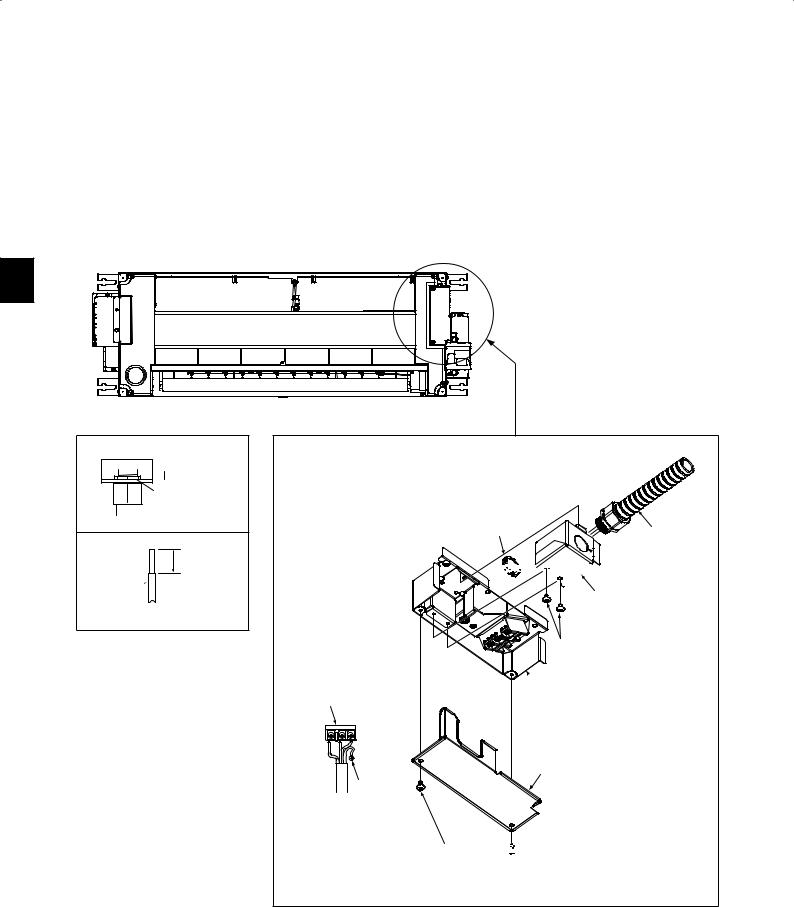
1)Remove the electrical cover (1).
2)Remove the conduit plate.
3)Attach the conduit pipe to the conduit plate with the lock nut. The indoor/outdoor unit connecting wire D appearing from the inside of conduit pipe should be less than 7/8 in. (23 mm). (Fig. 1)
4)Process the end of ground wire (Fig. 2). Connect it to the ground terminal of the electrical parts box.
5)Process the end of indoor/outdoor unit connecting wire D (Fig. 2). Attach it to the terminal block. Be careful not to make mis-wiring. Attach the wire to the terminal block securely so that its core cannot be seen, and no external force affects the connecting section of the terminal block.
6)Firmly tighten the terminal screws. After tightening, verify that the wires are tightly fastened.
7)Reinstall the conduit plate.
Conduit plate

 Less than 7/8 in.
 (23 mm) Lock nut
 Conduit pipe
Fig. 1
 9/16 in. (15 mm)
Lead  wire
wire 
Fig. 2
Lock nut |
Conduit pipe |


 ø7/8 in. (ø22.2 mm)
Conduit plate
Screw
 Electrical box
Terminal block
Electrical cover (1)
Grounding terminal
Screw 


•For future servicing, give extra length to the connecting wires.
•Do not fold the excess wire, or cram it into small space. Take caution not to damage the wires.
•Be sure to attach each screw to its correspondent terminal when securing the cord and/or the wire to the terminal block.
En-7
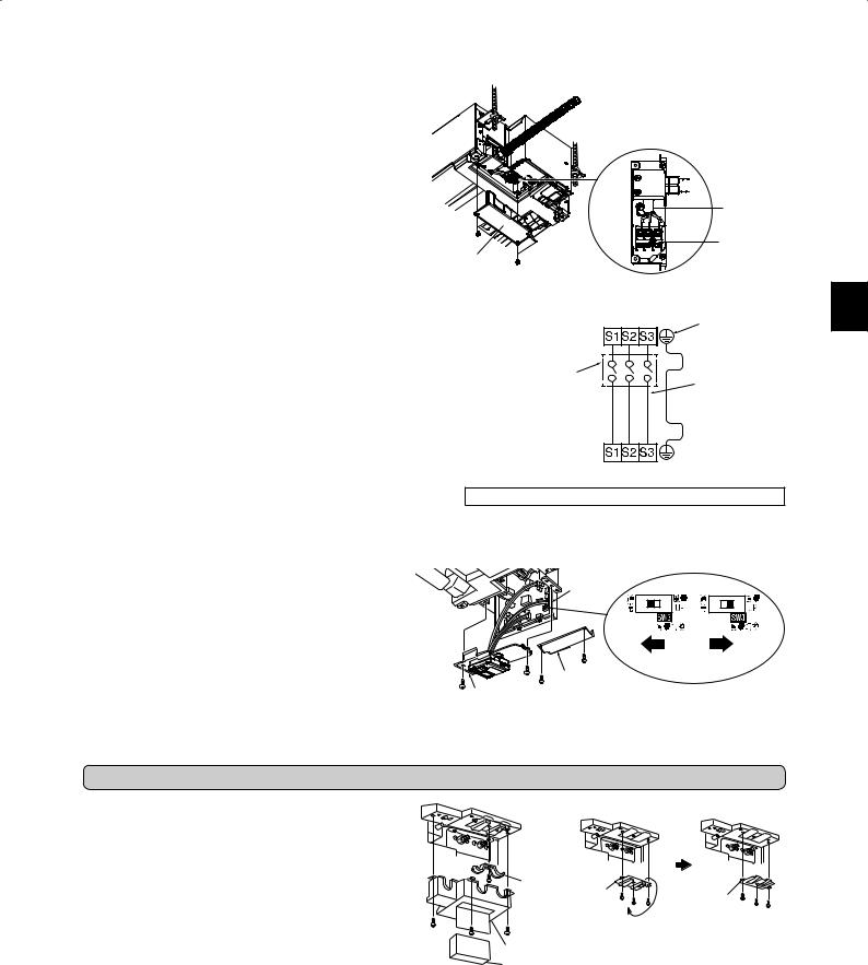
8) Pass indoor/outdoor unit connecting wire D process the end of the wire.
9) Loosen terminal screw, and connect first the ground wire, then indoor/ outdoor unit connecting wire D to the terminal block. Be careful not to make mis-wiring. Fix the wire to the terminal block securely so that no part of its core is appeared, and no external force is conveyed to the connecting section of the terminal block.
10)Firmly tighten the terminal screws to prevent them from loosening. After tightening, pull the wires lightly to confirm that they do not move.
11)Reinstall the electrical cover (1).
Electrical cover (1)
Indoor/outdoor |
unit connecting |
wire D |
Terminal block |
Indoor terminal block |
Grounding |
|
terminal* |
Disconnect switch |
Indoor/outdoor unit |
|
|
|
connecting wire D |
Remark:
*Use a ring tongue terminal in order to connect a ground
wire to terminal.
Outdoor terminal block
• For future servicing, give extra length to the connecting wires.
When the ceiling is above 8 ft. (2.4 m) and 9 ft. (2.7 m) or below
Move the slide switch (SW3) to the right to increase airflow volume.
*When the ceiling is above 9 ft. (2.7 m), airflow volume may be insufficient even with the slide switch (SW3) set to “increase airflow”.
1)Make sure that the breaker for air conditioner is turned OFF.
2)Remove electrical cover (1) and (2) of the indoor unit.
3)Slide out the electronic control P.C. board, and switch up the slide switch (SW).
4)Put the electronic control P.C. board back to the original position, and install electrical cover (1) and (2).
Note:
•Perform static elimination before setting.
•Default setting is Normal.
Electronic |
Slide switch SW3 |
control P.C. |
|
board |
|
|
Normal Increase airflow |
Electrical cover (1) |
volume |
Electrical cover (2) |
|
3. FLARING WoRK AND PIPE CoNNECtIoN
3-1. PIPING WoRK
1) Remove the pipe cover, hose band, pipe band, and spacer (cushion) of the indoor unit. Dispose of the spacer (cushion), as it will not be needed.
2) When using pipe with super insulating material (about ø1-7/8 in. (ø48 mm) liquid pipe, ø2 in. (ø51 mm) gas pipe) for indoor connecting pipe, remove plate and turn it over so that the concave part faces upward.
[When using pipe with super insulating material]
 Plate
Plate
Pipe band
Plate |
Plate |
|
(turn over) |
||
|
Pipe cover
Spacer (cushion)
En-8
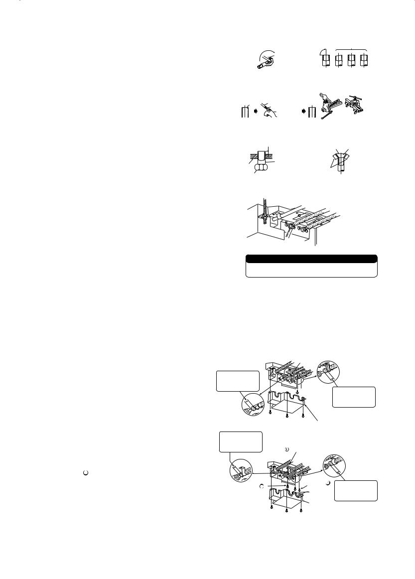
3-2. FLARING WoRK
1)Cut the copper pipe correctly with pipe cutter. (Fig. 1, 2)
2)Completely remove all burrs from the cut cross section of pipe. (Fig. 3)
•Put the end of the copper pipe to downward direction as you remove burrs in order to avoid to let burrs drop in the piping.
3)Remove flare nuts attached to indoor and outdoor units, then put them on pipe having completed burr removal. (Not possible to put them on after flaring work.)
4)Flaring work (Fig. 4, 5). Firmly hold copper pipe in the dimension shown in the table. Select A inch (mm) from the table according to the tool you use.
5)Check
•Compare the flared work with Fig. 6.
•If flare is noted to be defective, cut off the flared section and do flaring work again.
|
|
|
|
|
|
|
|
|
|
|
Pipe |
B inch |
|
A inch (mm) |
Tightening torque |
||
|
|
diameter |
Clutch |
Clutch |
Wing nut |
ft-lb |
|
|
|
|
(mm) |
type tool |
type tool |
type tool |
N•m |
||
|
|
inch (mm) |
(kgf•cm) |
|||||
|
|
|
for R410A |
for R22 |
for R22 |
|
||
|
|
|
|
|
|
|||
|
|
ø1/4 |
21/32 |
|
|
0.06 to |
10 to 13 |
13.7 to |
|
(6.35) |
(17) |
|
|
(140 to 180) |
17.7 |
||
|
|
|
|
|
|
0.08 |
|
|
|
|
ø3/8 |
7/8 |
|
0.04 to |
25 to 30 |
34.3 to |
|
|
0 to 0.02 |
(1.5 to 2.0) |
||||||
|
(9.52) |
(22) |
0.06 |
|
(350 to 420) |
41.2 |
||
|
|
ø1/2 |
1-1/32 |
(0 to 0.5) |
(1.0 to |
0.08 to |
36 to 42 |
49.0 to |
|
(12.7) |
(26) |
|
1.5) |
(500 to 575) |
56.4 |
||
|
|
|
|
|
|
0.10 |
|
|
|
|
ø5/8 |
1-5/32 |
|
|
54 to 58 |
73.5 to |
|
|
|
|
(2.0 to 2.5) |
|||||
|
(15.88) |
(29) |
|
|
|
(750 to 800) |
78.4 |
|
3-3. PIPE CoNNECtIoN
•In case of reconnecting the refrigerant pipes after detaching, make the flared part of pipe re-fabricated.
•Fasten flare nut with a torque wrench as specified in the table.
•When fastened too tight, flare nut may brake after a long period and cause refrigerant leakage.
•Be sure to wrap insulation around the piping. Direct contact with the bare piping may result in burns or frostbite.
Indoor unit connection
Connect both liquid and gas pipings to indoor unit.
•Apply a thin coat of refrigeration oil on the seat surface of pipe.
•For connection, first align the center, then tighten the first 3 to 4 turns of flare nut.
•Use tightening torque table above as a guideline for indoor unit side union joint section, and tighten using two wrenches. Excessive tightening damages the flare section.
outdoor unit connection
Connect pipes to stop valve pipe joint of the outdoor unit in the same manner applied for indoor unit.
•For tightening, use a torque wrench or spanner and use the same tightening torque applied for indoor unit.
3-4. INSTALLING THE PIPE COVER
Make sure to install the pipe cover. Incorrect installation results in water leakage.
•No insulation is needed on the pipe connecting part of the indoor side for this unit. The pipe cover gathers the water condensed around the pipe connecting part.
1)Install the pipe band removed in 3-1. to secure the connecting pipes. * The pipe band should hold down the insulating material of connecting pipe. Insulating material should protrude 3/8 in. (10 mm) or more than the pipe band, as shown in the illustration on the right.
2)Install pipe cover.
When using pipe with super insulating material
(about ø1-7/8 in. (ø48 mm) liquid pipe, ø2 in. (ø51 mm) gas pipe)
1)Make sure that the plate is turned over, and the concave part is facing upward. (Refer to 3-1.)
2)Use band  provided with the unit. (Do not use the pipe band attached to the unit)
3)Connecting pipe exit of pipe cover is precut. Cut it along the line.
4)Install pipe cover.
Note:
Install pipe cover and pipe band securely. Incomplete installation will cause water to drip from the unit, soaking and damaging household goods.
|
|
Good |
No good |
|
|
90° |
|
|
Copper |
|
|
|
pipe |
|
|
|
|
Tilted Uneven Burred |
|
|
Fig. 1 |
|
Fig. 2 |
|
|
Flaring tool |
|
Burr |
Copper pipe |
|
|
Spare reamer |
|
|
|
|
|
|
|
|
Pipe cutter |
|
|
|
|
Clutch type Wing nut type |
|
|
Fig. 3 |
|
Fig. 4 |
|
A |
|
Inside is shin- |
|
|
Smooth all |
ing without any |
|
|
around |
scratches. |
Die |
Copper pipe |
Even length |
|
|
|
||
Flare nut |
|
all around |
|
|
|
|
|
|
Fig. 5 |
|
Fig. 6 |
 WARNING
When installing the unit, securely connect the refrigerant pipes before starting the compressor.
Pipe band
Insulating material should protrude 3/8 in. (10 mm) or more than the edge of pipe band
[When using pipe with super |
|
Pipe cover |
insulating material] |
|
|
|
|
|
Insulating material |
|
|
should protrude 3/8 in. |
|
|
(10 mm) or more than |
|
|
the edge of pipe band |
Band |
(accessory part) |
|
||
Fixing screw |
|
Fixing screw |
|
|
|
|
|
Cut |
|
|
Pipe cover |
Insulating material should protrude 3/8 in. (10 mm) or more than the edge of pipe band
Insulating material should protrude 3/8 in. (10 mm) or more than the edge of pipe band
En-9
4. TEST RUN
4-1. TEST RUN
•Do not operate the unit for long periods at places such as building under construction. This may cause dust or odor to adhere to the unit.
•Perform test run with the attendance of user, as much as possible.
1)Press the E.O. SW once for COOL, and twice for HEAT operation. Test run will be performed for 30 minutes. If the left lamp of the operation indicator blinks every 0.5 seconds, inspect the indoor/outdoor unit
connecting wire Dfor mis-wiring. After the test run, emergency mode (set temperature 75°F (24°C)) will start.
2)To stop operation, press the E.O. SW several times until all LED lamps turn off. Refer to operating instructions for details.
Checking the remote (infrared) signal reception
Press the OFF/ON button on the remote controller  and check that an electronic sound is heard from the indoor unit. Press the OFF/ON button again to turn the air conditioner off.
•Once the compressor stops, the restart preventive device operates so the compressor will not operate for 3 minutes to protect the air conditioner.
Water drainage check
1)Fill the drain pan with about 0.9–1.0 liters of water. (Don’t pour water directly into the drain pump.)
2)Make a test run of the unit (in Cooling mode).
3)Check for water drainage at the outlet of the drainage pipe.
4)Stop the test run. (Don’t forget to turn off the power.)
Cover
Emergency |
E.O.SW |
operation switch |
|
(E.O. SW) |
|
4-2. WATER DRAINAGE CHECK FOR INDOOR uNIt oNLY
If the wiring work has not been completed, connect terminals S1 and S2 on the indoor terminal block to a 208/230 V single-phase power supply.
1) Start the drain pump test run.
•Press the emergency operation switch for 5 seconds (until a beep is heard) to start the operation of only the drain pump.
•The two operation monitor lamps start blinking.
2) Stop the drain pump test run.
•Press the emergency operation switch again to stop the operation of the drain pump. Even if you do not stop the drain pump, it will stop automatically after 15 minutes.
•The operation monitor lamps turn off.
4-3. AUTO RESTART FUNCTION
This product is equipped with an auto restart function. When the power supply is stopped during operation, such as during blackouts, the function automatically starts operation in the previous setting once the power supply is resumed. (Refer to the operating instructions for details.)
4-4. EXPLANATION TO THE USER
•Using the OPERATING INSTRUCTIONS, explain to the user how to use the air conditioner (how to use the remote controller, how to remove the air filters, how to remove or put the remote controller in the remote controller holder, how to clean, precautions for operation, etc.)
•Recommend the user to read the OPERATING INSTRUCTIONS carefully.
5. GRILLE (oPtIoN) INstALLAtIoN
Refer to the procedures indicated in the installation manual of the Grille (option).
Water bottle
Caution:
•After test run or remote signal reception check, turn off the unit with the E.O. SW or the remote controller before turning off the power supply. Not doing so will cause the unit to start operation automatically when power supply is resumed.
to the user
•After installing the unit, make sure to explain the user about auto restart function.
•If auto restart function is unnecessary, it can be deactivated. Consult the service representative to deactivate the function. Refer to the service manual for details.
En-10
 Loading...