


|
|
|
|
|
|
|
|
|
|
|
|
|
|
|
|
|
|
|
|
|
|
|
|
|
|
|
|
|
|
|
|
|
|
|
|
|
|
|
|
|
|
|
|
|
|
|
|
|
|
|
|
|
|
|
|
|
|
|
|
|
|
|
|
Revision A: |
|
|
|
|
|
|
|
|
|
|
|
|
|
|
|
|
|
|
|
|
|
|
|
|
|
|
|
|
|
|
|
|
||
|
|
|
|
|
|
|
|
|
|
|
|
|
|
|
|
|
|
|
|
|
|
|
|
|
|
|
|
|
|
|
||
|
|
|
|
|
|
|
|
|
|
|
|
|
|
|
|
|
|
|
|
|
|
|
|
|
|
|
|
|
|
|
● Power input of SPECIFICATION has modified. |
|
|
|
|
|
|
|
|
|
|
|
|
|
|
|
|
|
|
|
|
|
|
|
|
|
|
|
|
|
|
|
|
||
|
|
|
|
|
|
|
|
|
|
|
|
|
|
|
|
|
|
|
|
|
|
|
|
|
|
|
|
|
|
|
● Model name of remote controller has been |
|
FLOOR AND CEILING TYPE AIR CONDITIONERS |
||||||||||||||||||||||||||||||||
added to PARTS LIST. |
||||||||||||||||||||||||||||||||
|
|
|
|
|
|
|
|
|
|
|
|
|
|
|
|
|
|
|
|
|
|
|
|
|
|
|
|
|
|
|
|
|
Please void OB336.
No. OB336
REVISED EDITION-A
SERVICE MANUAL
Wireless type
Models
MCFH-A12WV- E1 (WH)
MCFH-A18WV- E1 (WH)
MCFH-A24WV- E1 (WH)
(When installed on the floor)
Indication of model name
MCFH-A12WV- E1 MCFH-A18WV- E1 MCFH-A24WV- E1
(When installed on the ceiling)
CONTENTS
1.TECHNICAL CHANGES ················
2.PART NAMES AND FUNCTIONS············
3.SPECIFICATION····················
4.NOISE CRITERIA CURVES ···············
5.OUTLINES AND DIMENSIONS ·············
6.WIRING DIAGRAM ··················
7.REFRIGERANT SYSTEM DIAGRAM ···········
8.SERVICE FUNCTIONS ·················
9.TROUBLESHOOTING·················
10.DISASSEMBLY INSTRUCTIONS·············
11.PARTS LIST······················
12.OPTIONAL PARTS···················
NOTE:
•This manual describes technical data of indoor units
•As for outdoor units MUCFH-A18/A24WV- E1 , refer to the service manual OB337 REVISED EDITION-A.
•As for outdoor unit MUH-A12YV- E1 , refer to the service manual OB331 REVISED EDITION-A.
•As for outdoor units MXZ-A18/A26/A32WV- E1 , refer to the service manual OB319.

Revision A:
•Power input of SPECIFICATION has modified.
•Model name of remote controller has been added to PARTS LIST.
1 
 TECHNICAL CHANGES
MCFH-13NV- E4 MCFH-A12WV- E1 |
MCFH-18NV- E3 MCFH-A18WV- E1 |
1.Rated voltage has changed. (220-240V 230V)
2.Indoor electronic control P.C. board has changed.
3.Horizontal vane has changed.
4.Terminal block has changed.
5.Indoor heat exchanger has changed.
6.Remote controller has changed. Econo cool operation has been added.
1.Rated voltage has changed. (220-240V 230V)
2.Indoor electronic control P.C. board has changed.
3.Horizontal vane has changed.
4.Terminal block has changed.
5.Indoor heat exchanger has changed.
6.Remote controller has changed. Econo cool operation has been added.
7.Indoor fan motor has changed. (RB4V25-AB RB4V25-AC) 7. Gas of union has changed. ({15.88 {12.7)
8.Indoor fan motor has changed. (RB4V36-AB RB4V36-AC)
MCFH-24NV- E3 MCFH-A24WV- E1
1.Rated voltage has changed. (220-240V 230V)
2.Indoor electronic control P.C. board has changed.
3.Horizontal vane has changed.
4.Terminal block has changed.
5.Indoor heat exchanger has changed.
6.Remote controller has changed. Econo cool operation has been added.
7.Liquid of union has changed. ({9.52 {6.35)
8.Indoor fan motor has changed. (RB4V36-AB RB4V36-DB)
2 
 PART NAMES AND FUNCTIONS
MCFH-A12WV - E1 MCFH-A18WV - E1 MCFH-A24WV - E1
INDOOR UNIT
(When installed on the floor)
Vertical vanes
Horizontal vane
Operation indicator lamp
Receiving section
Front panel
Air cleaning filter
(white bellows type)(option)
Air inlet
Air filter
Deodorizing filter
(gray sponge type)(option)
Operation section
(When the air inlet grille is opened.)


 Remote controller
(When installed on the ceiling)
Emergency operation switch
ACCESSORIES
|
Item |
Q'ty |
|
Installation plate |
2 |
|
Unit fixing screw |
2 |
|
5 o 12mm |
|
|
|
|
|
Wireless remote |
1 |
|
controller |
|
|
|
|
|
Remote controller |
1 |
|
mounting hardware |
|
|
|
|
|
Fixing screw for |
2 |
|
3.5 o 16mm (Black) |
|
|
|
|
|
Battery (AAA) for |
2 |
|
remote controller |
|
|
|
|
|
Drain hose |
1 |
|
Drain pipe cover |
1 |
|
Knockout cover |
1 |
|
Screw for 4 o 10mm |
2 |
2
MCFH-A12WV - E1
MCFH-A18WV - E1
MCFH-A24WV - E1
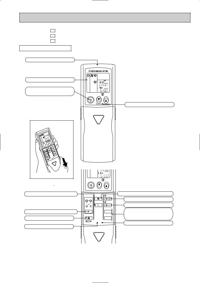
REMOTE CONTROLLER
Signal transmitting section
Operation display section
OPERATE /STOP (ON /OFF)button
|
|
PM |
|
|
AM |
ON/OFF |
TOO |
TOO |
|
WARM |
COOL |
TEMPERATURE buttons
Open the front lid. |
VANE CONTROL button
OPERATION SELECT button ECONO COOL button
RESET button
Indication of remote controller model  is on back.
AM |
ON/OFF |
TOO |
TOO |
|
WARM |
COOL |
FAN |
STOP |
FAN SPEED CONTROL button |
|
OFF-TIMER button |
|||
I FEEL COOL |
|
||
VANE |
START |
ON-TIMER button |
|
HEAT DRY |
|
||
MODE |
HR. |
HR. button |
|
|
|
||
ECONO COOL |
MIN. |
MIN. button |
|
|
|
(TIME SET button) |
|
RESET CLOCK |
|
CLOCK SET button |
|
|
|
3
3 SPECIFICATION
Indoor model
Function
Power supply
Capacity Air flow(High/Med.W/LowW)
|
|
Power outlet |
|
Electrical |
data |
Running current |
|
Power input |
|||
|
|
||
|
|
Auxiliary heater |
|
|
|
Power factor |
|
|
|
Fan motor current |
|
Fan |
motor |
Model |
|
Winding |
|||
|
|
||
|
|
resistance(at20:) |
|
|
|
Dimensions WOHOD |
|
|
|
Weight |
|
|
|
Air direction |
|
Special |
remarks |
Sound level(High/Med.W/LowW) |
|
Fan speed(High/Med.W/LowW) |
|||
|
|
||
|
|
Fan speed regulator |
|
|
|
Thermistor RT11(at25:) |
|
|
|
Thermistor RT12(at25:) |
|
|
|
Remote controller model |
|
|
|
|
|
MCFH-A12WV- E1 |
MCFH-A18WV- E1 |
MCFH-A24WV- E1 |
||||||
|
Cooling |
|
Heating |
Cooling |
|
Heating |
Cooling |
|
Heating |
|
|
|
|
Single phase |
|
|
|
||
|
|
|
|
230V, 50Hz |
|
|
|
||
K /h |
780/636W/492W |
840/696W/570W |
840/744W/642W |
||||||
A |
|
10 |
|
10 |
|
10 |
|||
A |
|
0.30 |
|
0.36 |
|
0.36 |
|||
W |
|
66 |
|
80 |
|
80 |
|||
A(kW) |
— |
|
— |
— |
|
— |
— |
|
— |
% |
|
96 |
|
97 |
|
97 |
|||
A |
|
0.30 |
|
0.36 |
|
0.36 |
|||
|
RB4V25-AC |
RB4V36-AC |
RB4V36-DB |
||||||
WHT-BLK 182.2 BLK-YLW 68.9 WHT-BLK 82.9 BLK-YLW 65.6 WHT-BLK 84.0 BLK-YLW 46.2
"YLW-BLU 47.5 BLU-BRN 31.5 YLW-BLU 36.0 BLU-BRN 27.0 YLW-BLU 37.2 BLU-BRN 45.2
|
BRN-RED 22.9 |
BRN-RED 13.7 |
BRN-RED 13.6 |
mm |
|
1100 650 180 |
|
kg |
25 |
25 |
25 |
|
5 |
5 |
5 |
dB |
46/41W/36W |
48/44W/39W |
48/45W/42W |
rpm |
1,240/1,060/845 |
1,320/1,145/960 |
1,320/1,190/1,060 |
|
3 |
3 |
3 |
k" |
10 |
10 |
10 |
k" |
10 |
10 |
10 |
|
KG04C |
KG04C |
KG04C |
|
|
|
|
NOTE: Test conditions are based on ISO 5151 |
|
|
Cooling : Indoor DB27°C WB19°C |
Heating : Indoor |
DB20°C WB 15°C |
Outdoor DB35°C WB(24°C) |
Outdoor |
DB 7°C WB 6°C |
Indoor-Outdoor piping length : 5 m |
|
|
w Reference value |
|
|
4
, MCFH-A18WV- E1 (WH), MCFH-A24WV- E1 (WH) Service Manual")
4 |
|
NOISE CRITERIA CURVES |
|
|
|
|
|
|
|
|
|
|
||||||||||
MCFH-A12WV - E1 |
|
|
|
|
|
|
|
MCFH-A18WV - E1 |
|
|
|
|
|
|||||||||
|
|
|
|
|
|
SPEED |
|
SPL(dB(A)) |
|
LINE |
|
|
|
|
|
SPEED |
SPL(dB(A)) |
|
LINE |
|||
|
|
|
|
|
|
High |
|
46 |
|
|
|
|
|
|
|
|
High |
|
48 |
|
|
|
|
|
|
|
|
|
Test conditions, |
|
|
|
|
|
|
|
|
Test conditions, |
|
|
|||||
|
|
|
|
|
|
|
Cooling : DB 27: WB 19:\ |
|
|
|
|
|
|
Cooling : DB 27: WB 19:\ |
||||||||
|
|
90 |
|
|
|
|
Heating : DB 20: WB 15: |
|
90 |
|
|
|
|
Heating : DB 20: WB 15: |
||||||||
|
|
|
|
|
|
|
|
|
|
|
|
|
|
|
|
|
|
|
|
|
||
BAR |
|
|
|
|
|
|
|
|
|
|
|
|
BAR |
|
|
|
|
|
|
|
|
|
MICRO |
|
80 |
|
|
|
|
|
|
|
|
|
|
MICRO |
80 |
|
|
|
|
|
|
|
|
redB0.0002 |
|
60 |
|
|
|
|
|
|
|
|
|
|
redB0.0002 |
60 |
|
|
|
|
|
|
|
|
|
|
70 |
|
|
|
|
|
|
|
|
|
NC-70 |
|
70 |
|
|
|
|
|
|
|
NC-70 |
|
|
|
|
|
|
|
|
|
|
|
|
|
|
|
|
|
|
|
|
|
||
LEVEL, |
|
|
|
|
|
|
|
|
|
|
|
NC-60 |
LEVEL, |
|
|
|
|
|
|
|
|
NC-60 |
PRESSURE |
|
50 |
|
|
|
|
|
|
|
|
|
|
PRESSURE |
50 |
|
|
|
|
|
|
|
|
|
|
|
|
|
|
|
|
|
|
|
NC-50 |
|
|
|
|
|
|
|
|
NC-50 |
||
|
|
|
|
|
|
|
|
|
|
|
|
|
|
|
|
|
|
|
|
|
||
|
|
40 |
|
|
|
|
|
|
|
|
|
|
|
40 |
|
|
|
|
|
|
|
|
SOUND |
|
|
|
|
|
|
|
|
|
|
|
NC-40 |
SOUND |
|
|
|
|
|
|
|
|
NC-40 |
|
30 |
|
|
|
|
|
|
|
|
|
|
30 |
|
|
|
|
|
|
|
|
||
|
|
|
|
|
|
|
|
|
|
|
|
|
|
|
|
|
|
|
|
|
||
BAND |
|
|
|
|
|
|
|
|
|
|
|
NC-30 |
BAND |
|
|
|
|
|
|
|
|
NC-30 |
|
20 |
APPROXIMATE |
|
|
|
|
|
|
|
|
20 |
APPROXIMATE |
|
|
|
|
|
|
||||
OCTAVE |
|
THRESHOLD OF |
|
|
|
|
|
|
|
|
OCTAVE |
THRESHOLD OF |
|
|
|
|
|
|
||||
|
|
|
|
|
|
|
|
|
|
|
|
|
|
|
|
|
||||||
|
|
|
HEARING FOR |
|
|
|
|
|
|
|
NC-20 |
|
|
HEARING FOR |
|
|
|
|
|
NC-20 |
||
|
|
|
|
|
|
|
|
|
|
|
|
CONTINUOUS |
|
|
|
|
|
|||||
|
|
|
CONTINUOUS |
|
|
|
|
|
|
|
|
|
|
|
|
|
|
|
|
|||
|
|
10 |
NOISE |
|
|
|
|
|
|
|
|
|
|
10 |
NOISE |
|
|
|
|
|
|
|
|
|
63 |
125 |
250 |
500 |
1000 |
2000 |
4000 |
8000 |
|
63 |
125 |
250 |
500 |
1000 |
2000 |
4000 |
8000 |
||||
|
|
|
|
|
||||||||||||||||||
|
|
|
|
|
BAND CENTER FREQUENCIES, Hz |
|
|
|
|
|
|
BAND CENTER FREQUENCIES, Hz |
|
|||||||||
MCFH-A24WV - E1 |
|
|
|
|
|
|
|
|
|
|
|
|
|
|
|
|
|
|||||
|
|
|
|
|
|
SPEED |
SPL(dB(A)) |
|
LINE |
|
|
|
|
|
|
|
|
|
|
|||
|
|
|
|
|
|
High |
|
|
48 |
|
|
|
|
|
|
|
INDOOR UNIT |
|
|
|||
|
|
|
|
|
|
|
|
|
|
|
|
|
|
|
|
|
|
|
||||
|
|
|
|
|
|
Test conditions, |
|
|
|
|
|
|
|
|
|
|
|
|
|
|||
|
|
|
|
|
|
|
Cooling : DB 27: WB 19:\ |
|
|
MICROPHONE |
|
|
|
|
|
|||||||
|
90 |
|
|
|
|
Heating : DB 20: WB 15: |
|
|
|
|
|
|
|
WALL |
|
|
||||||
|
|
|
|
|
|
|
|
|
|
|
|
|
|
|
|
|
|
|
|
|||
BAR |
|
|
|
|
|
|
|
|
|
|
|
|
|
|
|
1m |
1m |
|
|
|
|
|
|
|
|
|
|
|
|
|
|
|
|
|
|
|
|
|
|
|
|
|
|||
MICRO |
|
|
|
|
|
|
|
|
|
|
|
|
|
|
|
|
|
|
|
|
|
|
80 |
|
|
|
|
|
|
|
|
|
|
|
|
|
|
|
|
|
|
|
|
||
0.0002redB |
|
|
|
|
|
|
|
|
|
|
|
|
|
|
|
|
|
|
|
|
||
70 |
|
|
|
|
|
|
|
|
|
NC-70 |
|
|
|
|
|
|
|
|
|
|
||
|
|
|
|
|
|
|
|
|
|
|
|
|
|
|
|
|
|
|
|
|||
|
|
|
|
|
|
|
|
|
|
|
|
|
|
|
|
|
|
|
|
|
|
|
LEVEL, |
60 |
|
|
|
|
|
|
|
|
|
|
|
|
|
|
|
|
|
|
|
|
|
|
|
|
|
|
|
|
|
|
|
|
NC-60 |
|
|
|
|
|
|
|
|
|
|
|
|
|
|
|
|
|
|
|
|
|
|
|
|
|
|
|
|
|
|
|
|
|
|
PRESSURE |
50 |
|
|
|
|
|
|
|
|
|
|
|
|
|
|
|
|
|
|
|
|
|
|
|
|
|
|
|
|
|
|
|
|
NC-50 |
|
|
|
|
|
|
|
|
|
|
|
|
40 |
|
|
|
|
|
|
|
|
|
|
|
|
|
|
|
|
|
|
|
|
|
SOUND |
|
|
|
|
|
|
|
|
|
|
|
NC-40 |
|
|
|
|
|
|
|
|
|
|
30 |
|
|
|
|
|
|
|
|
|
|
|
|
|
|
|
|
|
|
|
|
||
|
|
|
|
|
|
|
|
|
|
|
|
|
|
|
|
|
|
|
|
|
||
BAND |
|
|
|
|
|
|
|
|
|
|
|
NC-30 |
|
|
|
|
|
|
|
|
|
|
20 |
APPROXIMATE |
|
|
|
|
|
|
|
|
|
|
|
|
|
|
|
|
|
|
|||
OCTAVE |
THRESHOLD OF |
|
|
|
|
|
|
|
|
|
|
|
|
|
|
|
|
|
|
|||
|
|
|
|
|
|
|
|
|
|
|
|
|
|
|
|
|
|
|
|
|||
|
|
|
|
|
|
|
|
|
|
|
|
|
|
|
|
|
|
|
|
|
||
|
|
|
HEARING FOR |
|
|
|
|
|
|
|
NC-20 |
|
|
|
|
|
|
|
|
|
|
|
|
|
|
CONTINUOUS |
|
|
|
|
|
|
|
|
|
|
|
|
|
|
|
|
|
||
|
|
|
|
|
|
|
|
|
|
|
|
|
|
|
|
|
|
|
|
|
||
|
10 |
NOISE |
|
|
|
|
|
|
|
|
|
|
|
|
|
|
|
|
|
|
|
|
|
63 |
125 |
250 |
500 |
1000 |
|
2000 |
4000 |
|
8000 |
|
|
|
|
|
|
|
|
|
|
||
|
|
|
|
|
|
|
|
|
|
|
|
|
|
|
||||||||
|
|
|
|
BAND CENTER FREQUENCIES, Hz |
|
|
|
|
|
|
|
|
|
|
|
|
||||||
5
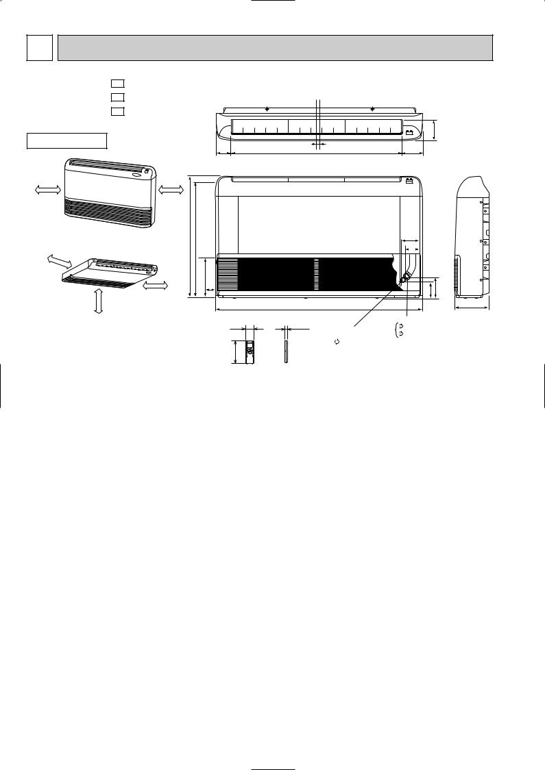
5 OUTLINES AND DIMENSIONS
MCFH-A12WV - E1
MCFH-A18WV - E1
MCFH-A24WV - E1
INDOOR UNIT
80.8
(When installed on the floor)
50cm or more |
50cm or more |
50cm |
|
650 |
616.5 |
(When installed on the ceiling) |
|
|
|
|
or |
|
|
|
more |
|
170 |
|
|
|
|
|
more |
50cm or more |
42.5 |
|
100cm or |
|
|
58
162
Unit: mm
114
906 |
16 |
112.8 |
|
|
93 |
|
|
77 |
|
|
113 |
143 |
1100 |
|
180 |
19 |
Gas line |
|
12.7 (MCFH-A12/A18WV) |
||
Liquid line |
15.88 (MCFH-A24WV) |
|
6.35 |
|
|
Wireless remote controller
6
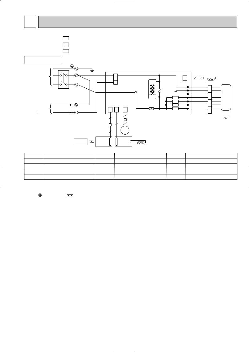
6 WIRING DIAGRAM
MCFH-A12WV - E1 |
MODELS WIRING DIAGRAM |
|
|
|
||||
MCFH-A18WV - E1 |
|
|
|
|
|
|
|
|
MCFH-A24WV - E1 |
|
|
|
|
|
|
|
|
INDOOR UNIT |
TB1 |
|
|
|
|
|
|
|
|
|
|
|
|
|
|
|
|
PE |
|
GRN/YLW |
|
|
|
|
|
|
POWER |
N |
|
BLU |
|
|
|
|
|
SUPPLY |
|
1 |
|
|
|
CN |
||
~/N 230V |
|
|
|
HIC1 |
|
|
||
|
|
|
2 |
|
|
|||
50Hz |
|
|
RED |
|
|
|
112 |
|
L |
|
3 |
|
|
|
|
||
|
|
|
|
|
LDCOM |
|||
|
|
|
CN201 |
NR11 |
||||
|
|
|
|
|
||||
CIRCUIT BREAKER |
|
BRN |
|
TAB12 |
|
LDC11 |
||
|
|
|
|
C11 LDC12 |
||||
|
|
|
|
|
||||
|
|
|
|
|
TRANS |
|
X144 |
LDFH |
|
TB2 |
|
|
|
|
|
LDFM |
|
|
BLU |
|
|
|
|
SR143 |
||
TO OUTDOOR |
|
|
|
|
LDFL |
|||
N |
|
|
|
F11 |
|
SR142 |
||
UNIT |
|
|
|
|
|
|
||
CONNECTING |
3 |
|
CN |
CN |
CN |
|
SR141 LDFVL |
|
12V |
|
101 |
113 |
151 ELECTRONIC CONTROL P.C BOARD |
||||
|
|
|
|
6 |
|
|
|
|
|
|
|
5 |
|
|
|
|
|
|
|
|
|
|
|
|
|
|
|
|
|
|
4 |
5 |
|
|
|
|
|
|
5 |
|
MV |
|
|
|
|
REMOTE |
DISP/ |
SW/THERMO |
|
|
|
||
|
RECEIVER |
P.C.BOARD |
|
|
|
|||
|
CONTROLLER |
|
|
|
||||
|
P.C.BOARD |
|
|
|
|
|
||
|
|
|
|
RT11 |
|
|
|
|
|
|
|
|
|
|
|
|
|
2 |
2 |
|
RT12 |
|
|
|
|
|
WHT |
1 |
WHT |
|
ORN |
2 |
ORN |
|
RED |
3 |
RED |
|
BLK |
4 |
BLK MF |
|
YLW |
5 |
YLW |
|
BLU |
6 |
BLU |
|
BRN |
7 |
BRN |
|
|
8 |
GRN/YLW |
SYMBOL |
|
NAME |
SYMBOL |
NAME |
SYMBOL |
NAME |
C11 |
INDOOR FAN CAPACITOR |
MV |
VANE MOTOR |
SR141~SR143 SOLID STATE RELAY |
||
F11 |
FUSE (3.15A) |
|
NR11 |
VARISTOR |
TB1, TB2 |
TERMINAL BLOCK |
HIC1 |
DC/DC CONVERTER |
RT11 |
ROOM TEMPERATURE THERMISTOR |
X144 |
RELAY |
|
MF |
INDOOR FAN MOTOR(INNER FUSE) |
RT12 |
INDOOR COIL THERMISTOR |
|
|
|
NOTES: 1.About the outdoor side electric wiring refer to the outdoor unit electric wiring diagram for servicing. |
|
|
||||
2.Use copper conductors only. (For field wiring) |
|
|
|
|||
3.Symbols below indicate. |
|
|
|
|
||
|
: Terminal block |
: Connector |
|
|
|
|
7
7 |
|
|
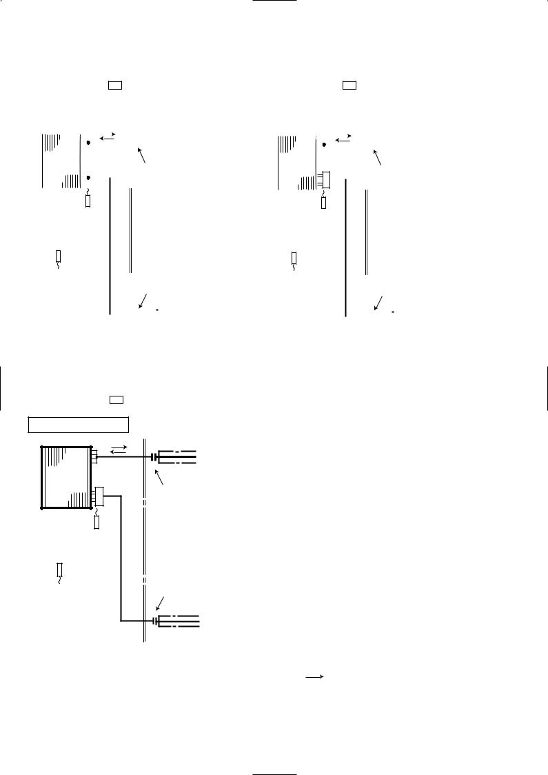
REFRIGERANT SYSTEM DIAGRAM |
|
|
|
|
|
|
|
|
|
|
|
|
|
|
|
|
|
|
|
|||||||||||||||||||||
|
|
|
|
|
|
|
|
|
|
|
|
|
|
|
|
|
|
|
|
|
|
|
|
|
|
|
|
|
|
|
|
|
|
|
|
|
|
|
|
|
|
|
|
|
|
|
|
|
|
|
|
|
|
|
|
|
|
|
|
|
|
|
|
|
|
|
|
|
|
|
|
|
|
|
|
|
|
|
|
|
|
|
|
|
|
|
Unit : mm |
MCFH-A12WV- E1 |
MCFH-A18WV- E1 |
|
|
|
|
|
|
|
|
|
|
|
|
||||||||||||||||||||||||||||||
|
|
|
|
|
|
|
|
|
|
|
|
|
|
|
|
|
|
|
|
|
|
|
|
||||||||||||||||||||
|
INDOOR UNIT |
|
|
|
|
|
|
|
|
|
|
|
|
|
|
|
|
|
|
|
|
|
|
||||||||||||||||||||
|
|
|
Refrigerant pipe [12.7 |
|
INDOOR UNIT |
|
|
Refrigerant pipe [12.7 |
|||||||||||||||||||||||||||||||||||
|
|
|
|
|
|
|
|
|
|
|
|
|
|
|
|||||||||||||||||||||||||||||
|
|
|
|
|
|
|
|
|
|
|
|
|
|||||||||||||||||||||||||||||||
|
|
|
|
|
|
|
|
|
|
|
|
|
|
|
|
|
|
|
|
|
|
||||||||||||||||||||||
|
|
|
|
|
|
|
|
|
|
|
|
(with heat insulator) |
|
|
|
|
|
|
|
|
|
|
(with heat insulator) |
||||||||||||||||||||
|
Indoor |
|
|
|
|
|
|
|
|
|
|
|
|
|
|
|
|
|
|
|
|
Indoor |
|
|
|
|
|
|
|
|
|
|
|
|
|
|
|
|
|
|
|
||
|
|
|
|
|
|
|
|
|
|
|
|
|
|
|
|
|
|
|
|
|
|
|
|
|
|
|
|
|
|
|
|
|
|
|
|
|
|
|
|
||||
|
heat |
|
Distributor |
|
Flared connection |
|
heat |
Distributor |
|
|
|
|
|
|
|
|
|
|
|
|
|||||||||||||||||||||||
|
exchanger |
|
|
exchanger |
|
Flared connection |
|||||||||||||||||||||||||||||||||||||
|
|
|
|
|
|
|
|
|
|
|
|
|
|
|
|
|
|
|
|||||||||||||||||||||||||
|
|
|
|
|
|
|
|
|
|
|
|
|
|
|
|
|
|
|
|
|
|
|
|
|
|
|
|
|
|
|
|
|
|
|
|
|
|
|
|
|
|
|
|
|
|
|
|
|
|
|
|
|
|
|
|
|
|
|
|
|
|
|
|
|
|
|
|
|
|
|
|
|
|
|
|
|
|
|
|
|
|
|
|
|
|
|
|
|
|
|
|
|
|
|
|
|
|
|
|
|
|
|
|
|
|
|
|
|
|
|
|
|
|
|
|
|
|
|
|
|
|
|
|
|
|
|
|
|
|
|
|
|
|
|
|
|
|
|
|
|
|
|
|
|
|
|
|
|
|
|
|
|
|
|
|
|
|
|
|
|
|
|
|
|
|
|
|
|
|
|
|
|
|
|
|
|
Indoor coil |
|
|
|
|
|
|
|
|
|
|
|
|
|
|
|
|
|
|
|
Indoor coil |
|
|
|
|
|
|
|
|
|
|
|
|
|
|
|
|
|
|
|
|||
|
thermistor |
|
|
|
|
|
|
|
|
|
|
|
|
|
|
|
|
|
|
|
thermistor |
|
|
|
|
|
|
|
|
|
|
|
|
|
|
|
|
|
|
|
|||
|
RT12 |
|
|
|
|
|
|
|
|
|
|
|
|
|
|
|
|
|
|
|
|
RT12 |
|
|
|
|
|
|
|
|
|
|
|
|
|
|
|
|
|
|
|
||
Room temperature |
|
|
|
|
|
|
|
|
|
|
|
|
|
Room temperature |
|
|
|
|
|
|
|
|
|
|
|
|
thermistor |
|
|
|
|
|
|
|
|
|
|
|
|
|
thermistor |
|
|
|
|
|
|
|
|
|
|
|
|
|
|
|
|
|
|
|
|
|
|
|
|
|
|
|
|
|
|
|
|
|
|
|
|
|
||
RT11 |
|
|
Flared connection |
RT11 |
|
|
Flared connection |
|||||||||||||||||||
|
|
|
|
|
|
|
|
|
|
|
|
|
|
|
|
|
|
|
|
|
|
|
|
|
|
|
|
|
|
|
|
|
|
|
|
|
|
|
|
|
|
|
|
|
|
|
|
|
|
|
|
|
|
|
|
|
Refrigerant pipe |
|
|
|
|
|
|
|
|
|
|
|
||||||||||||
|
|
|
|
|
|
Refrigerant pipe |
||||||||||||||||||||
|
|
|
[6.35 |
|
|
|
|
|
|
|
|
|
|
[6.35 |
|
|
|
|
|
|
||||||
|
|
|
(with heat insulator) |
|
|
|
(with heat insulator) |
|||||||||||||||||||
MCFH-A24WV- E1
INDOOR UNIT |
Refrigerant pipe [15.88 |
|
|
|
(with heat insulator) |
Indoor |
|
|
heat |
Distributor |
|
exchanger |
|
Flared connection |
|
|
|
Indoor coil |
|
|
thermistor |
|
|
RT12 |
|
|
Room temperature |
Flared connection |
thermistor |
|
RT11 |
|
Refrigerant pipe [6.35
(with heat insulator)
 Refrigerant flow in cooling
Refrigerant flow in heating
8
 Loading...