


|
|
|
|
|
|
|
|
|
|
|
|
|
|
|
|
|
|
|
|
|
|
|
|
|
|
|
|
|
|
|
|
|
|
|
|
|
|
|
|
|
|
|
|
|
|
|
|
|
|
|
|
|
|
|
|
|
|
|
|
|
|
|
|
|
|
|
|
|
|
|
|
|
|
|
|
|
|
|
|
|
|
|
|
|
|
|
|
|
|
|
|
|
|
|
|
|
|
|
|
|
|
|
|
|
|
|
|
|
Revision A: |
|
|||||
|
|
|
|
|
|
|
|
|
|
|
|
|
|
|
|
|
|
|
|
|
|
|
||||||
|
|
|
|
|
|
|
|
|
|
|
|
|
|
|
|
|
|
|
|
|
|
|||||||
|
|
|
|
|
|
|
|
|
|
|
|
|
|
|
|
|
|
|
|
|
|
|||||||
|
|
|
|
|
|
|
|
|
|
|
|
|
|
|
|
|
|
|
|
|
|
● MCFZ-A18WV- |
E1 |
and MCFZ-A24WV- |
E1 |
|
|
|
|
|
|
|
|
|
|
|
|
|
|
|
|
|
|
|
|
|
|
|
|
|
|
|
|
|
|||
|
|
|
|
|
|
|
|
|
|
|
|
|
|
|
|
|
|
|
|
|
|
have been added. |
|
|||||
FLOOR AND CEILING TYPE AIR CONDITIONERS |
||||||||||||||||||||||||||||
|
|
|
|
|
|
|||||||||||||||||||||||
Please void OB344. |
||||||||||||||||||||||||||||
|
|
|
|
|
|
|
|
|
|
|
|
|
|
|
|
|
|
|
|
|
|
|||||||
|
|
|
|
|
|
|
|
|
|
|
|
|
|
|
|
|
|
|
|
|
|
|
|
|
|
|
|
|
No. OB344
REVISED EDITION-A
SERVICE MANUAL
Wireless type Models
MCFZ-A12WV MCFZ-A18WV MCFZ-A24WV
-E1 (WH)
-E1 (WH)
-E1 (WH)
CONTENTS
(When installed on the floor)
Indication of model name
MCFZ-A12WV - E1 MCFZ-A18WV - E1 MCFZ-A24WV - E1
(When installed on the ceiling)
1.PART NAMES AND FUNCTIONS··········
2.SPECIFICATION·················
3.NOISE CRITERIA CURVES ············
4.OUTLINES AND DIMENSIONS ···········
5.WIRING DIAGRAM ················
6.REFRIGERANT SYSTEM DIAGRAM ········
7.SERVICE FUNCTIONS ··············
8.TROUBLESHOOTING···············
9.DISASSEMBLY INSTRUCTIONS ··········
10.PARTS LIST···················
11.OPTIONAL PARTS ················
NOTE:
•This service manual describes technical data of indoor units.
•As for outdoor units MUZ-A12YV - E1 and MUZ-A12YVH - E1 , refer to the service manual OB328 REVISED EDITION-A.
•As for outdoor units MUZ-A18YV - E1 and MUZ-A24YV - E1 , refer to the service manual OB346 REVISED EDITION-A.
1 
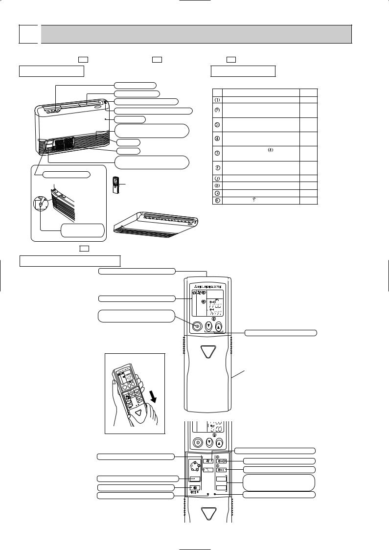
 PART NAMES AND FUNCTIONS
MCFZ-A12WV - E1 MCFZ-A18WV - E1 MCFZ-A24WV - E1 |
|
|||
INDOOR UNIT |
|
ACCESSORIES |
|
|
(When installed on the floor) |
Vertical vanes |
|
|
|
|
|
|
||
|
Horizontal vane |
Item |
Q'ty |
|
|
Operation indicator lamp |
Installation plate |
2 |
|
|
Unit fixing screw |
|
||
|
Remote control receiving section |
2 |
||
|
5 o 12mm |
|||
|
Front panel |
|
||
|
Wireless remote |
1 |
||
|
|
|||
|
Air cleaning filter |
controller |
||
|
|
|||
|
(White bellows type)(option) |
Remote controller |
1 |
|
|
Air inlet |
holder |
||
|
|
|||
|
Air filter |
Fixing screw for |
2 |
|
|
Deodorizing filter |
3.5 o 16mm (Black) |
||
|
|
|||
|
(Gray sponge type)(option) |
Battery (AAA) for |
2 |
|
|
|
remote controller |
||
Operation section |
|
|
||
|
Drain hose |
1 |
||
(When the air inlet grille is opened.) |
Remote controller |
|||
Drain pipe cover |
1 |
|||
|
||||
|
|
Knockout cover |
1 |
|
|
(When installed on the ceiling) |
Screw for 4 o 10mm |
2 |
|
|
|
|
||
Emergency operation switch
MCFZ-A12WV - E1
REMOTE CONTROLLER
Signal transmitting section
Operation display section
OPERATE/ STOP (ON/ OFF) button
|
|
PM |
|
|
AM |
ON/OFF |
TOO |
TOO |
|
WARM |
COOL |
TEMPERATURE buttons
Open the front lid. |
VANE CONTROL button
OPERATION SELECT button ECONO COOL button RESET button
Indication of remote controller model is on back.
|
|
|
AM |
|
|
ON/OFF |
TOO |
TOO |
|
|
|
WARM |
COOL |
|
|
|
|
|
FAN SPEED CONTROL button |
|
|
FAN |
STOP |
OFF-TIMER button |
|
I FEEL |
|
|
|
HEAT |
AUTO |
|
|
|
|
|
VANE |
START |
ON-TIMER button |
DRY COOL |
|
|
||
MODE |
|
HR. |
HR. button |
|
|
|
|
|
|
ECONO COOL |
|
MIN. |
MIN. button |
|
|
|
|
|
(TIME SET button) |
|
|
RESET CLOCK |
CLOCK SET button |
|
|
|
|
|
|
2
MCFZ-A18WV - E1 MCFZ-A24WV - E1
REMOTE CONTROLLER
Signal transmitting section
Operation display section
OPERATE/ STOP
(ON/ OFF)button
|
|
PM |
|
|
AM |
ON/OFF |
TOO |
TOO |
|
WARM |
COOL |
TEMPERATURE buttons
Open the front lid. |
VANE CONTROL button
OPERATION SELECT button ECONO COOL button
RESET button
Indication of remote controller model  is on back.
CLOCK |
PM |
AM |
ON/OFF |
TOO |
TOO |
|
WARM |
COOL |
FAN |
STOP |
FAN SPEED CONTROL button |
|
OFF-TIMER button |
|||
I FEEL COOL |
|
||
VANE |
START |
ON-TIMER button |
|
HEAT DRY |
|
||
MODE |
HR. |
HR. button |
|
|
|
||
ECONO COOL |
MIN. |
MIN. button |
|
|
|
(TIME SET button) |
|
RESET CLOCK |
|
CLOCK SET button |
|
|
|
3
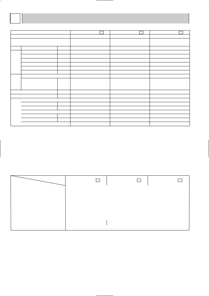
2 SPECIFICATION
Indoor model
Function
Power supply
Capacity Air flow(High/Med.W/LowW)
|
|
Power outlet |
|
Electrical |
data |
Running current 1 |
|
Power input 1 |
|||
|
|
||
|
|
Auxiliary heater |
|
|
|
Power factor 1 |
|
|
|
Fan motor current 1 |
|
Fan |
motor |
Model |
|
Winding |
|||
|
|
||
|
|
resistance(at 20:) |
|
|
|
Dimensions WOHOD |
|
|
|
Weight |
|
|
|
Air direction |
|
|
|
||
|
|
Sound level(High/Med.W/LowW) |
|
Special |
remarks |
Fan speed(High/Med.W/LowW) |
|
Thermistor RT11(at 25:) |
|||
|
|
Fan speed regulator |
|
|
|
Thermistor RT12(at 25:) |
|
|
|
Remote controller model |
|
|
|
|
|
MCFZ-A12WV - E1 |
MCFZ-A18WV - E1 |
MCFZ-A24WV - E1 |
||||||
|
Cooling |
|
Heating |
Cooling |
|
Heating |
Cooling |
|
Heating |
|
Single phase |
Single phase |
Single phase |
||||||
|
230V, 50Hz |
230V, 50Hz |
230V, 50Hz |
||||||
K /h |
780/636W/492W |
840/696W/570W |
840/744W/642W |
||||||
A |
|
10 |
|
10 |
|
10 |
|||
A |
|
0.30 |
|
0.36 |
|
0.36 |
|||
W |
|
66 |
|
80 |
|
80 |
|||
A(kW) |
— |
|
— |
— |
|
— |
— |
|
— |
% |
|
96 |
|
97 |
|
97 |
|||
A |
|
0.30 |
|
0.36 |
|
0.36 |
|||
|
RB4V25-AC |
RB4V36-AC |
RB4V36-DB |
||||||
WHT-BLK 182.2 BLK-YLW 68.9 WHT-BLK 82.9 BLK-YLW 65.6 WHT-BLK 84.0 BLK-YLW 46.2
"YLW-BLU 47.5 BLU-BRN 31.5 YLW-BLU 36.0 BLU-BRN 27.0 YLW-BLU 37.2 BLU-BRN 45.2
|
BRN-RED 22.9 |
BRN-RED 13.7 |
BRN-RED 13.6 |
mm |
1,100 O 650 O 180 |
1,100 O 650 O 180 |
1,100 O 650 O 180 |
kg |
25 |
25 |
25 |
|
5 |
5 |
5 |
dB |
46/41W/35W |
48/44W/39W |
48/45W/42W |
rpm |
1,240/1,060W/845W |
1,320/1,145/960 |
1,320/1,190/1,060 |
|
3 |
3 |
3 |
k" |
10 |
10 |
10 |
k" |
10 |
10 |
10 |
|
KG04B |
KG04C |
KG04C |
NOTE: Test conditions are based on ISO 5151
Cooling : Indoor Dry-bulb temperature 27°C Wet-bulb temperature 19°C Outdoor Dry-bulb temperature 35°C Wet-bulb temperature (24°C)
Heating : Indoor Dry-bulb temperature 20°C Wet-bulb temperature 15°C Outdoor Dry-bulb temperature 7°C Wet-bulb temperature 6°C
Indoor-Outdoor piping length (one way) : 5 m w Reference value
1 Measured under rated operating frequency.
Specifications and rating conditions of main electric parts
INDOOR UNIT
Item |
Model |
MCFZ-A12WV - E1 |
MCFZ-A18WV - E1 |
MCFZ-A24WV - E1 |
|
|
|
|
|
|
|
|
|
|
Indoor fan capacitor |
(C11) |
|
1.8+ 440V |
|
Fuse |
(F11) |
|
250V 3.15A |
|
Vane motor |
(MV) |
|
MP20 12V 250" |
|
Varistor |
(NR11) |
|
ERZV10D471/ TNR10V471K410 |
|
Solid state relay (SR141~SR143) |
|
AQG12212/ G3MC-201PL |
|
|
|
|
|
|
|
Terminal block |
(TB1/TB2) |
|
3P/ 4P |
|
|
|
|
|
|
Relay |
(X144) |
|
G5NB-1A-DC12V/ G5N-1A-DC12V |
|
|
|
|
|
|
Compressor contactor |
(52C) |
ALF1T12 |
– |
|
|
|
|
|
|
Indoor fan motor thermal fuse |
|
145 i 2: |
|
|
4

3 NOISE CRITERIA CURVES
MCFZ-A12WV - E1 |
MCFZ-A18WV - E1 |
SPEED SPL(dB(A)) LINE
High 46
SPEED SPL(dB(A)) LINE
High 48
Test conditions,
Cooling : Dry-bulb temperature 27: Wet-bulb temperature 19: Heating : Dry-bulb temperature 20: Wet-bulb temperature 15:
|
90 |
|
|
|
|
|
|
|
|
BAR |
|
|
|
|
|
|
|
|
|
MICRO |
80 |
|
|
|
|
|
|
|
|
|
|
|
|
|
|
|
|
|
|
dB re 0.0002 |
70 |
|
|
|
|
|
|
|
NC-70 |
|
|
|
|
|
|
|
|
||
60 |
|
|
|
|
|
|
|
|
|
LEVEL, |
|
|
|
|
|
|
|
|
|
|
|
|
|
|
|
|
|
NC-60 |
|
50 |
|
|
|
|
|
|
|
|
|
PRESSURE |
|
|
|
|
|
|
|
|
|
|
|
|
|
|
|
|
|
NC-50 |
|
40 |
|
|
|
|
|
|
|
|
|
|
|
|
|
|
|
|
|
NC-40 |
|
SOUND |
|
|
|
|
|
|
|
|
|
30 |
|
|
|
|
|
|
|
|
|
|
|
|
|
|
|
|
|
NC-30 |
|
BAND |
|
|
|
|
|
|
|
|
|
20 |
APPROXIMATE |
|
|
|
|
|
|
||
OCTAVE |
THRESHOLD OF |
|
|
|
|
|
|
||
|
|
|
|
|
|
|
|||
|
HEARING FOR |
|
|
|
|
|
NC-20 |
||
|
CONTINUOUS |
|
|
|
|
|
|||
|
|
|
|
|
|
|
|||
10 |
NOISE |
|
|
|
|
|
|
|
|
|
|
|
|
|
|
|
|
||
|
63 |
125 |
250 |
500 |
1000 |
2000 |
4000 |
8000 |
|
|
|
||||||||
BAND CENTER FREQUENCIES, Hz
Test conditions,
Cooling : Dry-bulb temperature 27: Wet-bulb temperature 19:\ Heating : Dry-bulb temperature 20: Wet-bulb temperature 15:
|
90 |
|
|
|
|
|
|
|
|
BAR |
|
|
|
|
|
|
|
|
|
MICRO |
80 |
|
|
|
|
|
|
|
|
|
|
|
|
|
|
|
|
|
|
dB re 0.0002 |
70 |
|
|
|
|
|
|
|
NC-70 |
|
|
|
|
|
|
|
|
||
60 |
|
|
|
|
|
|
|
|
|
LEVEL, |
|
|
|
|
|
|
|
|
NC-60 |
50 |
|
|
|
|
|
|
|
|
|
PRESSURE |
|
|
|
|
|
|
|
|
|
|
|
|
|
|
|
|
|
NC-50 |
|
40 |
|
|
|
|
|
|
|
|
|
|
|
|
|
|
|
|
|
NC-40 |
|
SOUND |
|
|
|
|
|
|
|
|
|
30 |
|
|
|
|
|
|
|
|
|
|
|
|
|
|
|
|
|
NC-30 |
|
BAND |
|
|
|
|
|
|
|
|
|
20 |
APPROXIMATE |
|
|
|
|
|
|
||
OCTAVE |
THRESHOLD OF |
|
|
|
|
|
|
||
|
|
|
|
|
|
|
|||
|
HEARING FOR |
|
|
|
|
|
NC-20 |
||
|
CONTINUOUS |
|
|
|
|
|
|||
|
|
|
|
|
|
|
|||
10 |
NOISE |
|
|
|
|
|
|
|
|
|
|
|
|
|
|
|
|
||
|
63 |
125 |
250 |
500 |
1000 |
2000 |
4000 |
8000 |
|
|
|
||||||||
BAND CENTER FREQUENCIES, Hz
MCFZ-A24WV - E1
SPEED SPL(dB(A)) LINE
High 48
Test conditions,
Cooling : Dry-bulb temperature 27: Wet-bulb temperature 19:\ Heating : Dry-bulb temperature 20: Wet-bulb temperature 15:
|
90 |
|
|
|
|
|
|
|
|
BAR |
|
|
|
|
|
|
|
|
|
MICRO |
80 |
|
|
|
|
|
|
|
|
|
|
|
|
|
|
|
|
|
|
dB re 0.0002 |
70 |
|
|
|
|
|
|
|
NC-70 |
|
|
|
|
|
|
|
|
||
60 |
|
|
|
|
|
|
|
|
|
LEVEL, |
|
|
|
|
|
|
|
|
NC-60 |
50 |
|
|
|
|
|
|
|
|
|
PRESSURE |
|
|
|
|
|
|
|
|
|
|
|
|
|
|
|
|
|
NC-50 |
|
40 |
|
|
|
|
|
|
|
|
|
|
|
|
|
|
|
|
|
NC-40 |
|
SOUND |
|
|
|
|
|
|
|
|
|
30 |
|
|
|
|
|
|
|
|
|
|
|
|
|
|
|
|
|
NC-30 |
|
BAND |
|
|
|
|
|
|
|
|
|
20 |
APPROXIMATE |
|
|
|
|
|
|
||
OCTAVE |
THRESHOLD OF |
|
|
|
|
|
|
||
|
|
|
|
|
|
|
|||
|
HEARING FOR |
|
|
|
|
|
NC-20 |
||
|
CONTINUOUS |
|
|
|
|
|
|||
|
|
|
|
|
|
|
|||
10 |
NOISE |
|
|
|
|
|
|
|
|
|
|
|
|
|
|
|
|
||
|
63 |
125 |
250 |
500 |
1000 |
2000 |
4000 |
8000 |
|
|
|
||||||||
INDOOR UNIT
MICROPHONE
WALL
1m
1m
BAND CENTER FREQUENCIES, Hz
5
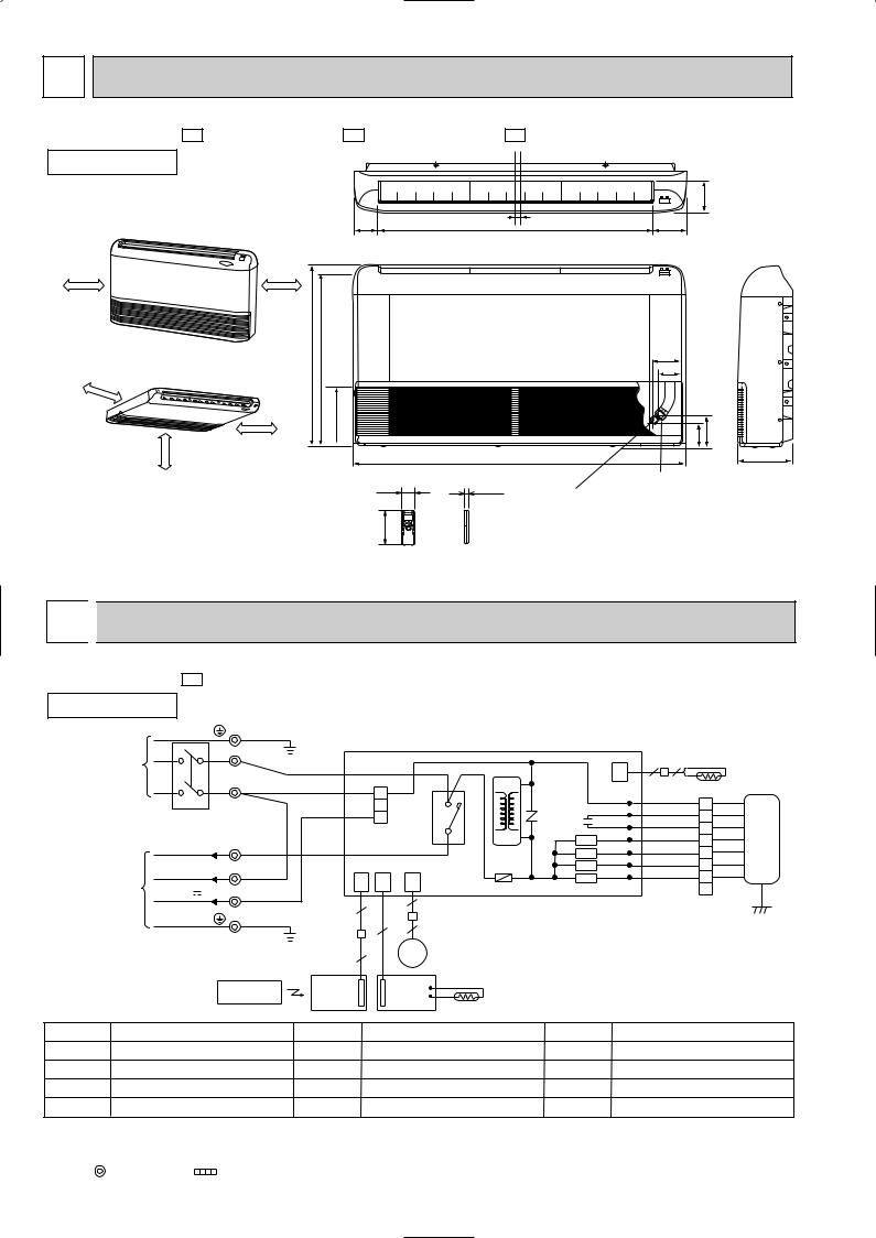
4 OUTLINES AND DIMENSIONS
MCFZ-A12WV - E1 MCFZ-A18WV - E1 MCFZ-A24WV - E1
INDOOR UNIT
(When installed on the floor) |
80.8 |
906 |
16 |
|
|||
500mm or more |
500mm or more |
|
|
650 |
616.5 |
500mm |
(When installed on the ceiling) |
or |
|
|
more |
moreor1000mm |
500mm or more |
|
42.5 170

1100
58 |
19 |
Liquid line  6.35
6.35
162
Wireless remote controller
Unit: mm
114
112.8
93
77
113 |
143 |
180
Gas line
 9.52(MCFZ-A12WV)
 12.7(MCFZ-A18WV)
  15.88(MCFZ-A24WV)
5 
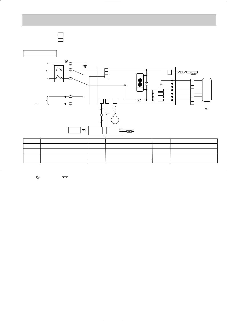
 WIRING DIAGRAM
MCFZ-A12WV -
INDOOR UNIT
E1 |
MODEL WIRING DIAGRAM |
|
PE TB1 GRN/YLW
POWER |
|
L |
|
|
|
|
|
|
|
|
2 |
2 |
|
|
|
SUPPLY |
|
|
|
BRN |
|
|
|
HIC1 |
|
CN |
|
RT12 |
|||
~/N 230V |
|
|
|
|
|
|
|
|
|
|
|||||
|
|
|
|
|
|
|
|
112 |
|
|
|
||||
50Hz |
|
N |
BLU |
|
1 |
|
|
|
|
|
|
WHT |
|
WHT |
|
|
|
|
|
|
|
4 |
|
|
LDCOM |
|
|
|
|||
|
|
|
|
|
2 |
|
NR11 |
|
|
|
|
||||
|
|
|
|
|
|
C11 |
LDC12 |
|
RED |
3 |
RED |
|
|||
|
|
|
|
|
52C |
|
|
|
LDC11 |
|
ORN |
1 |
ORN |
|
|
|
CIRCUIT BREAKER |
|
|
3 |
3 |
|
|
|
|
|
2 |
|
|
||
|
|
2TB2 WHT |
CN201 |
|
|
X144 |
LDFH |
|
BLK |
4 |
BLK |
MF |
|||
|
|
|
|
|
|
|
|
||||||||
|
230V~ |
|
|
|
|
|
SR143 LDFM |
|
YLW |
5 |
YLW |
||||
|
|
|
|
|
|
|
|
F11 |
SR142 LDFL |
|
BLU |
6 |
BLU |
|
|
TO OUTDOOR |
|
N |
BLU |
CN |
CN |
CN |
|
|
SR141 LDFVL |
|
BRN 7 |
BRN |
|
||
UNIT |
12V |
3 |
RED |
101 |
113 |
151 |
ELECTRONIC CONTROL P.C BOARD |
|
|
8 |
GRN/YLW |
||||
CONNECTING |
5 |
|
6 |
|
|
|
|
|
|
|
|||||
|
|
|
|
|
|
|
|
|
|
|
|||||
|
|
|
|
|
|
|
|
|
|
|
|
|
|
||
|
|
|
|
|
|
|
|
|
|
|
|
|
|
|
|
GRN/YLW
4 5
|
|
|
|
5 |
MV |
|
|
|
|
REMOTE |
DISP/ |
|
SW/THERMO |
|
|
|
|
RECEIVER |
|
|
|
||
|
|
CONTROLLER |
|
P.C.BOARD |
|
|
|
|
|
P.C.BOARD |
|
|
|
||
|
|
|
|
RT11 |
|
|
|
|
|
|
|
|
|
|
|
SYMBOL |
|
NAME |
SYMBOL |
|
NAME |
SYMBOL |
NAME |
C11 |
INDOOR FAN CAPACITOR |
MV |
VANE MOTOR |
SR141~SR143 SOLID STATE RELAY |
|||
F11 |
FUSE (3.15A) |
|
NR11 |
VARISTOR |
TB1, TB2 |
TERMINAL BLOCK |
|
HIC1 |
DC/DC CONVERTER |
RT11 |
ROOM TEMPERATURE THERMISTOR |
X144 |
RELAY |
||
MF |
INDOOR FAN MOTOR(INNER FUSE) |
RT12 |
INDOOR COIL THERMISTOR |
52C |
COMPRESSOR CONTACTOR |
||
NOTES: 1.About the outdoor side electric wiring refer to the outdoor unit electric wiring diagram for servicing. |
|
|
|||||
2.Use copper conductors only. (For field wiring) |
|
|
|
|
|||
3.Symbols below indicate. |
|
|
|
|
|
||
|
: Terminal block |
: Connector |
|
|
|
|
|
6
MCFZ-A18WV - E1 |
MODELS WIRING DIAGRAM |
|
|
|
||||
MCFZ-A24WV - E1 |
|
|
|
|
|
|
|
|
INDOOR UNIT |
TB1 |
|
|
|
|
|
|
|
|
|
|
|
|
|
|
|
|
PE |
|
GRN/YLW |
|
|
|
|
|
|
POWER |
N |
|
BLU |
|
|
|
|
|
SUPPLY |
|
1 |
|
|
|
CN |
||
~/N 230V |
|
|
|
HIC1 |
|
|
||
|
|
|
2 |
|
|
|||
50Hz |
|
|
RED |
|
|
|
112 |
|
L |
|
3 |
|
|
|
|
||
|
|
|
|
|
LDCOM |
|||
|
|
|
CN201 |
NR11 |
||||
|
|
|
|
|
||||
CIRCUIT BREAKER |
|
BRN |
|
TAB12 |
|
LDC11 |
||
|
|
|
|
C11 LDC12 |
||||
|
|
|
|
|
||||
|
|
|
|
|
|
|
X144 LDFH |
|
|
TB2 |
BLU |
|
|
|
|
SR143 |
LDFM |
TO OUTDOOR |
|
|
|
|
LDFL |
|||
N |
|
|
|
F11 |
|
SR142 |
||
UNIT |
|
|
|
|
|
|
||
CONNECTING |
3 |
|
CN |
CN |
CN |
|
SR141 LDFVL |
|
12V |
|
101 |
113 |
151 ELECTRONIC CONTROL P.C BOARD |
||||
|
|
|
|
6 |
|
|
|
|
|
|
|
5 |
|
|
|
|
|
|
|
|
|
|
|
|
|
|
|
|
|
|
4 |
5 |
|
|
|
|
|
|
5 |
|
MV |
|
|
|
|
REMOTE |
DISP/ |
SW/THERMO |
|
|
|
||
|
RECEIVER |
P.C.BOARD |
|
|
|
|||
|
CONTROLLER |
|
|
|
||||
|
P.C.BOARD |
|
|
|
|
|
||
|
|
|
|
RT11 |
|
|
|
|
|
|
|
|
|
|
|
|
|
2 |
2 |
|
RT12 |
|
|
|
|
|
WHT |
1 |
WHT |
|
ORN |
2 |
ORN |
|
RED |
3 |
RED |
|
BLK |
4 |
BLK MF |
|
YLW |
5 |
YLW |
|
BLU |
6 |
BLU |
|
BRN |
7 |
BRN |
|
|
8 |
GRN/YLW |
SYMBOL |
|
NAME |
SYMBOL |
NAME |
SYMBOL |
NAME |
C11 |
INDOOR FAN CAPACITOR |
MV |
VANE MOTOR |
SR141~SR143 SOLID STATE RELAY |
||
F11 |
FUSE (3.15A) |
|
NR11 |
VARISTOR |
TB1, TB2 |
TERMINAL BLOCK |
HIC1 |
DC/DC CONVERTER |
RT11 |
ROOM TEMPERATURE THERMISTOR |
X144 |
RELAY |
|
MF |
INDOOR FAN MOTOR(INNER FUSE) |
RT12 |
INDOOR COIL THERMISTOR |
|
|
|
NOTES: 1.About the outdoor side electric wiring refer to the outdoor unit electric wiring diagram for servicing. |
|
|
||||
2.Use copper conductors only. (For field wiring) |
|
|
|
|||
3.Symbols below indicate. |
|
|
|
|
||
|
: Terminal block |
: Connector |
|
|
|
|
7
6 
 REFRIGERANT SYSTEM DIAGRAM
MCFZ-A12WV- |
E1 |
MCFZ-A18WV- |
|
|
|
INDOOR UNIT |
|
MCFZ-A24WV- |
E1
E1
Unit : mm
|
|
|
|
|
|
|
|
Refrigerant pipe [9.52 |
INDOOR UNIT |
|
||||||||||||||||||||||||||||
|
|
|
|
|
|
|
|
|
|
|
|
|
|
|
|
|
|
Refrigerant pipe [12.7(MCFZ-A18MV) |
||||||||||||||||||||
|
|
|
|
|
|
|
|
|
|
|
|
|
|
|
|
|
|
|||||||||||||||||||||
|
|
|
|
|
|
|
|
(with heat insulator) |
|
|
|
|
|
|
|
|
|
|
Refrigerant pipe [15.88(MCFZ-A24MV) |
|||||||||||||||||||
|
|
|
|
|
|
|
|
|
|
|||||||||||||||||||||||||||||
|
|
Muffler |
|
|
|
|
|
|
|
|
|
|
|
|
|
|
|
|
|
|
|
|
|
(with heat insulator) |
||||||||||||||
|
|
|
|
|
|
|
|
|
|
|
|
|
|
|
|
|
|
|
|
|
|
|
|
|
|
|
|
|
|
|
|
|
|
|
|
|
|
|
Indoor |
|
Indoor coil |
|
|
|
|
|
|
|
|
|
|
|
|
Indoor |
|
|
|
|
|
|
|
|
|
|
|
|
|
|
|
|
|
|
|
||||
heat |
|
thermistor |
|
Flared connection |
|
heat |
|
|
Distributor |
|
Flared connection |
|||||||||||||||||||||||||||
exchanger |
|
RT12 |
|
|
exchanger |
|
|
|
||||||||||||||||||||||||||||||
|
|
|
|
|
|
|
|
|
|
|
|
|
|
|
|
|
|
|
||||||||||||||||||||
|
|
|
|
|
|
|
|
|
|
|
|
|
|
|
|
|
|
|
|
|
|
|
|
|
|
|
|
|
|
|
|
|
|
|
|
|
|
|
|
|
|
|
|
|
|
|
|
|
|
|
|
|
|
|
|
|
|
|
|
|
|
|
|
|
|
|
|
|
|
|
|
|
|
|
|
|
|
|
|
|
|
|
|
|
|
|
|
|
|
|
|
|
|
|
|
|
Indoor coil |
|
|
|
|
|
|
|
|
|
|
|
|
|
|
|
|
|
|
|
|
|
|
|
|
|
|
|
|
|
|
|
|
|
|
|
|
|
|
thermistor |
|
|
|
|
|
|
|
|
|
|
|
|
|
|
|
|
|
|
|
|
|
|
|
|
|
|
|
|
|
|
|
|
|
|
|
|
|
|
RT12 |
|
|
|
|
|
|
|
|
|
|
|
|
|
|
|
|
|
|
|
Room temperature |
|
|
|
|
|
|
|
|
|
|
|
|
Room temperature |
|
|
|
|
|
|
|
|
|
|
|
|
thermistor |
|
Flared connection |
thermistor |
|
|
|
|
|
|
|
|
|
|
|
|||||||||||
|
RT11 |
|
Flared connection |
||||||||||||||||||||||
RT11 |
|
|
|||||||||||||||||||||||
|
|
|
|
|
|
|
|
|
|
|
|
|
|
|
|
|
|
|
|
|
|
|
|
|
|
|
|
|
|
|
|
|
|
|
|
|
|
|
|
|
|
|
|
|
|
|
|
|
|
|
|
|
|
|
|
|
|
|
|
|
|
|
|
|
|
|
|
|
|
|
|
|
|
|
|
|
|
|
|
Refrigerant pipe |
Refrigerant flow in cooling |
|
Refrigerant pipe |
||||||||||||||||||||
|
|
[6.35 |
|
|
|
|
|
|
[6.35 |
|
|
|
|
|
|
||||||||||
|
|
(with heat insulator) |
Refrigerant flow in heating |
|
(with heat insulator) |
||||||||||||||||||||
7 
 SERVICE FUNCTIONS
MCFZ-A12WV - E1 MCFZ-A18WV - E1 MCFZ-A24WV - E1
7-1. TIMER SHORT MODE
For service, set time can be shortened by short circuit of JPG and JPS on the electronic control P.C. board. The time will be shortened as follows. (Refer to page 17 or 18.)
3-minutes time delay : 3-minutes 3-seconds Set time : 1 minute 1-second
Set time : 3 minute 3-second (It takes 3 minutes for the compressor to start operation. However, the starting time is shortened by short circuit of JPG and JPS.)
7-2. P.C. BOARD MODIFICATION FOR INDIVIDUAL OPERATION
A maximum of 4 indoor units with wireless remote controllers can be used in a room. In this case, to operate each indoor unit individually by each remote controller, P.C. boards of remote controller must be modified according to the number of the indoor unit.
How to modify the remote controller P.C. board
Remove batteries before modification. The board has a print as shown below;
Remote controller model : KG04B(MCFZ-A12WV),KG04C(MCFZ-A18/A24WV)
J2
NOTE : For remodelling, take out the batteries and press the OPERATE/STOP(ON/OFF) button twice or 3 times at first.
After finish remodelling, put back the batteries then press the RESET button.
J1
The P.C. board has the print “J1” and “J2”. Solder “J1” and “J2” according to the number of indoor unit as shown in Table 1. After modification, press the RESET button.
8
 Loading...