


BNP-B3977A (ENG)
MDS-B Series
Linear Servo System
Specifications and Instruction Manual

Introduction
Thank you for purchasing the Mitsubishi linear servo system.
This instruction manual describes the handling and caution points for using this CNC.
Incorrect handling may lead to unforeseen accidents, so always read this instruction manual thoroughly to ensure correct usage.
Make sure that this instruction manual is delivered to the end user.
Precautions for safety
Please read this instruction manual and auxiliary documents before starting installation, operation, maintenance or inspection to ensure correct usage. Thoroughly understand the device, safety information and precautions before starting operation.
The safety precautions in this instruction manual are ranked as "DANGER" and
"CAUTION".

 DANGER

 CAUTION
When a dangerous situation may occur if handling is mistaken leading to fatal or major injuries.
When a dangerous situation may occur if handling is mistaken leading to medium or minor injuries, or physical damage.
Note that some items described as |
|
|
CAUTION |
may lead to major results |
|
|
|
|
|
depending on the situation. In any case, important information that must be observed is described.
The signs indicating prohibited and mandatory items are described below.
This sign indicates that the item is prohibited (must not be carried out). For example,  is used to indicate "Fire
Prohibited".
This sign indicates that the item is mandatory (must be carried out). For example,  is used to indicate grounding.
After reading this instruction manual, keep it in a safe place for future reference.
In this instruction manual, the cautions on a level that will not lead to physical damage and the cautions for special functions, etc., are ranked as "NOTICE", "INFORMATION" and "MEMO".
NOTICE |
: When a fault in the product will occur but physical damage will not |
|
occur if handling is mistaken. |
INFORMATION : When special functions will be started with parameter changes, or when there are other usage methods.
MEMO |
: Information that should be known for operation. |
I

For Safe Use
1. Special precautions for linear servo system
 DANGER
The linear servo system uses a powerful magnet on the secondary side. Thus, caution must be taken not only by the person installing the linear motor, but also the machine operators. For example, persons wearing a pacemaker, etc., must not approach the machine.
The person installing the linear motor and the machine operator must not have any items (watch or calculator, etc.) which could malfunction or break due to the magnetic force on their body.
Always use nonmagnetic tools for installing the linear motor or during work in the vicinity of the linear motor.
(Example of nonmagnetic tool)
Explosion-proof beryllium copper alloy safety tool: Nihon Gaishi
2. Electric shock prevention
 DANGER
Do not open the front cover while the power is ON or during operation. Failure to observe this could lead to electric shocks.
Do not operate the machine with the front cover removed. The high voltage terminals and charged sections will be exposed, and may pose a risk of electric shocks.
Do not remove the surface cover even when the power is OFF unless carrying out wiring work or periodic inspections. The inside of the servo amplifier is charged, and may pose a risk of electric shocks.
Wait at least 10 minutes after turning the power OFF, before starting wiring or inspections. Failure to observe this could lead to electric shocks.
Ground the servo amplifier and linear servomotor with Class 3 grounding or higher.
Wiring and inspection work must be done by a qualified technician.
Wire the servo amplifier and linear servomotor after installation. Failure to observe this could lead to electric shocks.
Do not touch the switches with wet hands. Failure to observe this could lead to electric shocks.
Do not damage, apply forcible stress, place heavy items or engage the cable. Failure to observe this could lead to electric shocks.
II

3. Fire prevention
 CAUTION
Install the servo amplifier, linear servomotor and regenerative resistor on noncombustible material. Direct installation on combustible material or near combustible materials could lead to fires.
If a servo amplifier fault should occur, turn OFF the power on the servo amplifier's power supply side. If a large current continues to pass, fires could occur.
Shut off the power with the error signal. Failure to do so could cause the regenerative resistor to abnormally overheat and fires to occur due to faults in the regenerative transistor, etc.
4. Injury prevention
 CAUTION
Do not apply a voltage other than that specified in Instruction Manual on each terminal. Failure to observe this item could lead to ruptures or damage, etc.
Do not mistake the terminal connections. Failure to observe this item could lead to ruptures or damage, etc.
Do not mistake the polarity(+, -) . Failure to observe this item could lead to ruptures or damage, etc.
Do not touch the servo amplifier fins, regenerative resistor or linear motor, etc., while the power is turned ON or immediately after turning the power OFF. Some parts are heated to high temperatures, and touching these could lead to burns.
III
5. Various precautions
Observe the following precautions. Incorrect handling of the unit could lead to faults, injuries and electric shocks, etc.
(1) Transportation and installation
 CAUTION
Correctly transport the product according to its weight.
Do not stack the products above the tolerable number.
Do not hold the front cover when transporting the servo amplifier. The unit could drop.
Follow this Instruction Manual and install the unit in a place where the weight can be borne.
Always store the secondary side of the linear servomotor in the delivered packaged state.
Do not get on top of or place heavy objects on the unit.
Always observe the installation directions.
During the interval from unpacking to installation, the risks posed by the magnetic attraction force in the secondary side of the linear servomotor will increase, so take special care, and install the correctly.
Secure the specified distance between the servo amplifier and control panel, or between the servo amplifier and other devices.
Do not install or run a servo amplifier or linear servomotor that is damaged or missing parts.
Do not let conductive objects such as screws or metal chips, etc., or combustible materials such as oil enter the servo amplifier or linear servomotor.
The servo amplifier and linear servomotor are precision devices, so do not drop them or apply strong impacts to them.
Store and use the units under the following environment conditions.
|
|
|
|
|
Conditions |
|
|
|
|
|
|
|
|
|
|
Environment |
Servo |
|
Scale I/F |
|
Pole |
|
|
|
|
detec-tion |
Linear servomotor |
||||
|
amplifier |
|
unit |
|
|||
|
|
|
unit |
|
|||
|
|
|
|
|
|
||
|
|
|
|
|
|
|
|
Ambient temperature |
|
|
0°C to +55°C |
|
0°C to +40°C |
||
(with no dew condensation) |
(with no dew condensation) |
||||||
|
|||||||
Ambient humidity |
|
90% (RH) or less |
|
80% (RH) or less |
|||
(with no dew condensation) |
(with no dew condensation) |
||||||
|
|||||||
Storage temperature |
|
–15°C to +70°C |
|
–15°C to +50°C |
|||
|
(with no freezing) |
|
(with no freezing) |
||||
|
|
|
|||||
Storage humidity |
|
|
90% (RH) or less (with no dew condensation) |
||||
Atmosphere |
Indoors (Where unit is not subject to direct sunlight) |
||||||
With no corrosive gas, combustible gas, oil mist or dust. |
|||||||
|
|||||||
Altitude |
|
|
1000m or less above sea level |
||||
|
|
|
|
|
|||
Vibration |
4.9m/s2 |
|
98m/s2 |
98m/s2 |
|||
IV

 CAUTION
Always use nonmagnetic tools when installing the linear servomotor.
Always mount a mechanical stopper on the end of the linear servomotor's travel path to avoid danger if the motor should go over the end.
Securely fix the linear servomotor onto the machine. Insufficient fixing could cause the servomotor to come off during operation.
Provide a cover on the movable sections of the linear servomotor so that they are never touched during operation.
When storing for a long time, please contact your dealer.
(2) Wiring
 CAUTION
Correctly and securely perform the wiring. Failure to do so could lead to runaway of the servomotor.
Do not install a phase advancing capacity, surge absorber or radio noise filter on the output side of the servo amplifier.
Correctly connect the output side (terminals U, V, W). Failure to do so could lead to abnormal operation of the servomotor.
Do not directly connect a commercial power supply to the linear servomotor. Doing so could lead to faults.
Make sure not to mistake the orientation of the surge absorbing diode installed on the DC relay for the control output signal. Failure to do so could cause a trouble preventing the signal from being output, or could inhibit operation of the protection circuit during an emergency stop, etc.
Do not connect/disconnect the cables connected between each unit while the power is ON.
Securely tighten the fixing screws and fixing mechanisms on the cable connectors. Insufficient fixing could cause the connectors to dislocate during operation.
Ground the shield cables indicated in the Connection Manual with a cable clamp, etc.
Separate the signal wire away from the power line/electricity line.
Use wires and cables having a wire diameter, heat resistance and bending characteristics compatible for the system.
V

(3) Trial operation and adjustment
 CAUTION
Check and adjust each parameter before starting operation. Failure to do so could lead to unforeseen operation of the machine.
Do not make remarkable adjustments and changes as the operation could become unstable.
(4) Usage methods
 CAUTION
Install an external emergency stop circuit so that the operation can be stopped and power shut OFF immediately.
Unqualified persons must not disassemble or repair the unit.
If the alarm is reset (RST) with the operation start signal (ST) ON, the servomotor will restart suddenly. Confirm that the operation signal is OFF before resetting. Failure to observe this could lead to accidents.
Never make modifications.
Reduce magnetic interference by installing a noise filter. The electronic devices used near the servo amplifier could be affected by magnetic noise.
Always use the linear servomotor and servo amplifier with the designated combination.
The linear servomotor basically does not have any devices such as the magnetic brakes installed. Thus, when using this for an axis onto which an unbalance force is applied, such as a gravity axis, install a stopping device on the machine side to secure safety.
Always carry out trial operation after changing the program or parameters, and after maintenance and inspection.
Do not enter the machine's movable range during automatic operation.
For an unbalanced axis, such as a gravity axis, basically balance it with a device such as a counterbalance. With the linear motor, the continuous thrust is lower than the rotary motor, so if the axis is unbalanced the motor's heating amount will increase. If an error should occur, the axis will drop naturally. This is hazardous as the dropping distance and dropping speed are large.
(5) Troubleshooting
 CAUTION
If a hazardous situation is predicted during stop or product trouble, install an external brake mechanism.
If an alarm occurs, remove the cause and secure the safety before resetting the alarm.
Never go near the machine after restoring the power after a failure, as the machine could start suddenly. (Design the machine so that personal safety can be ensured even if the machine starts
suddenly.)
VI

(6) Maintenance, inspection and part replacement
 CAUTION
Carry out maintenance and inspection after backing up the servo amplifier programs and parameters.
The capacity of the electrolytic capacitor will drop due to deterioration. To prevent secondary damage due to failures, replacing this part every five years when used under a normal environment is recommended. Contact the Service Center or Service Station for replacements.
Do not carry out a megger test (insulation resistance test) during the inspections.
If the battery warning is issued, save the machining program, tool data and parameters with an input/output device, and then replace the battery.
(7) Disposal
 CAUTION
Treat this unit as general industrial waste. Note that the MDS Series units with a heat radiating fin protruding from the back use alternate Freon, and thus cannot be treated as general industrial waste. Always return this part to the Service Center or Service Station.
A permanent magnet is used on the secondary side of the linear servomotor. This also must be returned to the Service Center or Service Station.
Do not disassemble the servo amplifier or linear servomotor parts.
(8) General precautions
 CAUTION
The drawings given in this Specifications and Maintenance Instruction Manual show the covers and safety partitions, etc., removed to provide a clearer explanation. Always return the covers or partitions to their respective places before starting operation, and always follow the instructions given in this manual.
VII
|
|
Contents |
|
Chapter 1 |
Outline |
|
|
1-1 |
Outline ..................................................................................................................... |
1-2 |
|
1-2 |
Features................................................................................................................... |
1-2 |
|
Chapter 2 Drive System Configuration |
|
||
2-1 |
Basic system configuration................................................................................... |
2-3 |
|
2-2 List of units and corresponding linear motors.................................................... |
2-4 |
||
2-3 Linear motor drive system..................................................................................... |
2-5 |
||
|
2-3-1 Standard linear servo system ......................................................................... |
2-5 |
|
|
2-3-2 Configuration of parallel drive system............................................................. |
2-8 |
|
Chapter 3 |
Selection |
|
|
3-1 Selecting the linear servomotor............................................................................ |
3-2 |
||
|
3-1-1 |
Max. feedrate.................................................................................................. |
3-2 |
|
3-1-2 |
Max. thrust ...................................................................................................... |
3-2 |
|
3-1-3 |
Continuous thrust............................................................................................ |
3-4 |
3-2 Selecting the power supply unit ........................................................................... |
3-6 |
||
3-3 Selecting the power supply capacity, wire size, AC reactor, |
|
||
|
contactor and NFB ................................................................................................. |
3-6 |
|
Chapter 4 Linear Servomotor Specifications |
|
||
4-1 |
Type configuration ................................................................................................. |
4-2 |
|
4-2 |
List of specifications.............................................................................................. |
4-3 |
|
4-3 Speed – torque characteristics drawing (At input voltage 200VAC) ................. |
4-4 |
||
4-4 |
Dynamic brake characteristics.............................................................................. |
4-5 |
|
4-5 |
Outline dimensions ................................................................................................ |
4-6 |
|
4-6 |
Explanation of connectors .................................................................................... |
4-9 |
|
Chapter 5 Servo Drive Specifications |
|
||
5-1 |
Type configuration ................................................................................................. |
5-2 |
|
5-2 |
List of specifications.............................................................................................. |
5-3 |
|
5-3 |
Overload protection specifications ...................................................................... |
5-4 |
|
5-4 |
Outline dimensions ................................................................................................ |
5-6 |
|
5-5 Explanation of connectors and terminal blocks.................................................. |
5-8 |
||
5-6 |
Dynamic brake unit ................................................................................................ |
5-9 |
|
|
5-6-1 Connection of dynamic brake unit .................................................................. |
5-9 |
|
|
5-6-2 Outline dimensions of dynamic brake unit ...................................................... |
5-10 |
|
5-7 |
Battery unit.............................................................................................................. |
5-10 |
|
|
5-7-1 Connection of battery unit............................................................................... |
5-10 |
|
|
5-7-2 Outline dimensions of battery unit .................................................................. |
5-10 |
|
Chapter 6 |
Detector Specifications |
|
|
6-1 |
Linear scale............................................................................................................. |
6-2 |
|
6-2 |
Scale I/F unit ........................................................................................................... |
6-3 |
|
|
6-2-1 Outline ............................................................................................................ |
6-3 |
|
|
6-2-2 |
Type configuration .......................................................................................... |
6-3 |
|
6-2-3 |
List of specifications........................................................................................ |
6-4 |
|
6-2-4 |
Outline dimensions ......................................................................................... |
6-5 |
|
6-2-5 |
Explanation of connectors .............................................................................. |
6-6 |
6-3 |
Pole detection unit ................................................................................................. |
6-7 |
|
|
6-3-1 |
Outline ............................................................................................................ |
6-7 |
i
|
6-3-2 |
Type configuration .......................................................................................... |
6-7 |
|
6-3-3 |
List of specifications........................................................................................ |
6-7 |
|
6-3-4 |
Outline dimensions ......................................................................................... |
6-8 |
|
6-3-5 |
Explanation of connectors .............................................................................. |
6-8 |
|
6-3-6 Installation....................................................................................................... |
6-9 |
|
Chapter 7 |
Installation |
|
|
7-1 Installation of the linear servomotor .................................................................... |
7-2 |
||
|
7-1-1 |
Environmental conditions................................................................................ |
7-3 |
|
7-1-2 Installing the linear servomotor....................................................................... |
7-3 |
|
|
7-1-3 Cooling of linear servomotor........................................................................... |
7-4 |
|
7-2 Installation of the servo amplifier ......................................................................... |
7-5 |
||
|
7-2-1 |
Environmental conditions................................................................................ |
7-5 |
|
7-2-2 Drive section wiring system diagram .............................................................. |
7-6 |
|
|
7-2-3 |
Installing the unit............................................................................................. |
7-7 |
|
7-2-4 Layout of each unit ......................................................................................... |
7-8 |
|
|
7-2-5 |
Main circuit connection ................................................................................... |
7-9 |
|
7-2-6 Connection of feedback cable ........................................................................ |
7-11 |
|
|
7-2-7 |
Link bar specifications .................................................................................... |
7-12 |
|
7-2-8 Separated layout of units ................................................................................ |
7-13 |
|
|
7-2-9 Installing multiple power supply units ............................................................. |
7-14 |
|
|
7-2-10 Installation for 2ch communication specifications with CNC, and |
|
|
|
|
installation of only one power supply unit ..................................................... |
7-16 |
|
7-2-11 Connection of battery unit............................................................................. |
7-17 |
|
|
7-2-12 Connection with mechanical brakes ............................................................. |
7-18 |
|
Chapter 8 Drive Section Connector and Cable Specifications |
|
||
8-1 |
Cable connection system ...................................................................................... |
8-2 |
|
|
8-1-1 |
Cable option list .............................................................................................. |
8-3 |
8-2 |
Cable connectors ................................................................................................... |
8-5 |
|
|
8-2-1 Servo amplifier CN1A, CN1B and CN9 cable connector ................................ |
8-5 |
|
|
8-2-2 Servo amplifier CN2 and CN3 cable connector .............................................. |
8-5 |
|
|
8-2-3 Servo amplifier CN20 connector (for mechanical brakes) .............................. |
8-5 |
|
|
8-2-4 MDS-B-HR, MDS-B-MD cable connector ....................................................... |
8-6 |
|
|
8-2-5 Power supply section power wire connector................................................... |
8-7 |
|
|
8-2-6 |
Flexible conduits ............................................................................................. |
8-10 |
|
|
(1) Method for connecting to a connector with back shell............................... |
8-10 |
|
|
(2) Method for connecting to the connector main body .................................. |
8-10 |
8-3 |
Cable clamp fitting ................................................................................................. |
8-11 |
|
8-4 Cable wire and assembly....................................................................................... |
8-12 |
||
8-5 |
Cable connection diagram..................................................................................... |
8-13 |
|
|
8-5-1 CNC unit bus cable......................................................................................... |
8-13 |
|
|
8-5-2 Absolute value scale coupling cable............................................................... |
8-14 |
|
|
8-5-3 Cable for amplifier – scale I/F unit .................................................................. |
8-15 |
|
|
8-5-4 Cable for scale I/F unit – scale ....................................................................... |
8-16 |
|
|
8-5-5 Cable for scale I/F unit – pole detector ........................................................... |
8-17 |
|
|
8-5-6 Cable for I/F unit – motor thermal ................................................................... |
8-17 |
|
|
8-5-7 |
Mechanical brake cable .................................................................................. |
8-18 |
Chapter 9 |
Setup |
|
|
9-1 Initial setup of servo drive unit ............................................................................. |
9-2 |
||
|
9-1-1 Setting the rotary switches.............................................................................. |
9-2 |
|
|
9-1-2 Transition of LED display after power is turned ON........................................ |
9-2 |
|
9-2 Setting the initial parameters ................................................................................ |
9-3 |
||
|
9-2-1 Setting the initial parameters .......................................................................... |
9-3 |
|
ii
|
(1) Command polarity/feedback polarity (SV017: SPEC) ............................... |
9-3 |
|
|
(2) Servo specifications (SV017: SPEC) ........................................................ |
9-4 |
|
|
(3) Ball screw pitch (SV018: PIT).................................................................... |
9-4 |
|
|
(4) Detector resolution (SV019: RNG1, SV020: RNG2) ................................. |
9-4 |
|
|
(5) Motor type (SV025: MTYP) ....................................................................... |
9-5 |
|
|
(6) Detector type (SV025: MTYP)................................................................... |
9-6 |
|
|
(7) Power supply type (SV036: PTYP)............................................................ |
9-7 |
|
9-2-2 Parameters set according to feedrate............................................................. |
9-8 |
||
9-2-3 Parameters set according to machine movable mass .................................... |
9-8 |
||
9-2-4 List of standard parameters for each motor.................................................... |
9-9 |
||
9-3 Initial setup of the linear servo system ................................................................ |
9-10 |
||
9-3-1 Installation of linear motor and linear scale .................................................... |
9-10 |
||
9-3-2 DC excitation function..................................................................................... |
9-13 |
||
9-3-3 Setting the pole shift ....................................................................................... |
9-15 |
||
9-3-4 Setting the parallel drive system..................................................................... |
9-17 |
||
9-3-5 Settings when motor thermal is not connected............................................... |
9-18 |
||
Chapter 10 |
Adjustment |
|
|
10-1 Measurement of adjustment data ....................................................................... |
10-2 |
||
10-1-1 |
D/A output specifications .............................................................................. |
10-2 |
|
10-1-2 Setting the output data.................................................................................. |
10-2 |
||
10-1-3 Setting the output scale ................................................................................ |
10-2 |
||
10-2 |
Gain adjustment ................................................................................................... |
10-3 |
|
10-2-1 |
Current loop gain .......................................................................................... |
10-3 |
|
10-2-2 |
Speed loop gain............................................................................................ |
10-3 |
|
10-2-3 |
Position loop gain ......................................................................................... |
10-5 |
|
10-3 |
Characteristics improvement .............................................................................. |
10-7 |
|
10-3-1 Optimal adjustment of cycle time.................................................................. |
10-7 |
||
10-3-2 |
Vibration suppression method ...................................................................... |
10-10 |
|
10-3-3 Improving the cutting surface precision ........................................................ |
10-11 |
||
10-3-4 Improvement of protrusion at quadrant changeover ..................................... |
10-13 |
||
10-3-5 |
Improvement of overshooting ....................................................................... |
10-18 |
|
10-3-6 Improvement of characteristics during acceleration/deceleration................. |
10-21 |
||
10-4 Setting for emergency stop ................................................................................. |
10-24 |
||
10-4-1 Vertical axis drop prevention control............................................................. |
10-24 |
||
10-4-2 |
Deceleration control...................................................................................... |
10-31 |
|
10-5 |
Collision detection ............................................................................................... |
10-32 |
|
10-6 |
Parameter list........................................................................................................ |
10-35 |
|
Chapter 11 |
Troubleshooting |
|
|
11-1 Points of caution and confirmation .................................................................... |
11-2 |
||
11-2 Troubleshooting at start up................................................................................. |
11-3 |
||
11-3 List of servo alarms and warnings ..................................................................... |
11-4 |
||
11-4 |
Alarm details ......................................................................................................... |
11-6 |
|
11-5 LED display Nos. at memory error...................................................................... |
11-8 |
||
11-6 Error parameter Nos. at initial parameter error ................................................. |
11-8 |
||
11-7 Troubleshooting for each servo alarm ............................................................... |
11-9 |
||
iii

Chapter 1 Outline
1-1 |
Outline .......................................................................................................... |
1-2 |
1-2 |
Features........................................................................................................ |
1-2 |
1–1

Chapter 1 Outline
1-1 Outline
In recent years, demands for high accuracy, high speed and high efficiency have increased in the field of machine tools. The application of a linear servo for the feed axis has increased as a measure to respond to the demands.
With the linear servo system, high speed and high acceleration characteristics can be achieved in respect to the ball screw drive system. Furthermore, as there is no ball wear, etc., which is the disadvantage of using a ball screw drive, the life of the machine can be extended. A response error caused by backlash or wear does not occur, so a high accuracy system can be structured.
The MELDAS linear servo system has been developed to realize a max. speed of 120m/min and acceleration of 98m/s2 (motor unit) as a standard.
1-2 Features
(1)Ample lineup (Seven models)
Machines can be handled flexiblely. Thus, thrust can be increased by using several motors for one axis.
(2)High speed and high acceleration
The max. speed is 2m/s as a standard. An acceleration of 98m/s2 is possible with the motor unit.
(3)Absolute position detection system
As the absolute position detection system, the Mitsutoyo linear scale AT342 and Heidenhain absolute position linear scale LC191M are compatible with the MELDAS high-speed serial communication specifications. (Both are battery-less)
(4)High performance servo drive
Compared to the conventional amplifier MDS-B-Vx, the servo processing performance has been greatly improved. The high-gain servo MDS-B-V14L has been developed to achieve high speed and more accurate machining in combination with the high frequency PWM control. Linear servo systems requiring a higher speed and accuracy are powerfully backed up by the high-gain servo MDS-B-V14L.
1–2

Chapter 2 Drive System Configuration
2.1 |
Basic system configuration ........................................................................ |
2-3 |
|
2-2 |
List of units and corresponding linear motors ......................................... |
2-4 |
|
2-3 |
Linear motor drive system .......................................................................... |
2-5 |
|
|
2-3-1 |
Standard linear servo system............................................................... |
2-5 |
|
2-3-2 |
Configuration of parallel drive system .................................................. |
2-8 |
2–1

Chapter 2 Drive System Configuration
 WARNING
All wiring work must be carried out by a qualified electrician.
Wait at least 10 minutes after turning the power OFF, before starting wiring or inspections. Failure to observe this could lead to electric shocks.
Install the servo amplifier and linear servomotor before staring wiring. Failure to observe this could lead to electric shocks.
Do not damage, apply forcible stress, place heavy things on, or catch the cables. Failure to observe this could lead to electric shocks.
 CAUTION
Correctly wire the machine. Failure to observe this could lead to runaway of the linear servomotor or injuries.
Make sure not to mistake the connection terminals. Failure to observe this could lead to ruptures or trouble.
Make sure not to mistake the polarity (+, –). Failure to observe this could lead to ruptures or trouble.
Make sure not to mistake the orientation of the surge absorbing diode installed on the DC relay for the control output signal. Failure to do so could cause a trouble preventing the signal from being output, or could inhibit operation of the protection circuit during an emergency stop, etc.
Do not install a phase-advancing capacitor, surge absorber or radio noise filter on the output side of the servo amplifier.
Shut off the power with the error signal. Failure to do so could cause the regenerative resistor to abnormally overheat and fires to occur due to faults in the regenerative transistor, etc.
Do not modify the machine.
2–2

Chapter 2 Drive System Configuration
2.1Basic system configuration
Example: One spindle axis + two rotary servo axes + one linear servo axis
MELDAS CNC
Servo drive unit |
Servo drive unit |
(two axes) |
(two axes) |
MDS-B-V24 |
MDS-B-V14L |
Spindle drive unit |
Power supply |
(one axis) |
unit |
MDS-B-SP |
MDS-B-CV |
|
8 8 |
|
|
8 8 |
|
8 8 |
|
|
8 8 |
|
|
|
Detector cable |
|
|
|
|
|
|
|
|
|
|
|
|
|
|
|
|
|
|
|
|
|
|
|
L+ |
|
|
|
|
|
|
|
|
|
|
|
|
L– |
For control circuit power supply (RS) |
|
|
|
|
|
|
|
|
|
|
|
L11 |
|
|
|
|
|
|
|
|
|
|
|
|
L21 |
|
U |
V |
W |
U |
V |
W |
U |
V |
W |
L1 |
L2 |
L3 |
|
|
|
|
|
Linear scale
Servomotor |
|
MDS- |
MC |
Spindle motor |
B-AL |
|
|
AC reactor |
|
|
3ø 200VAC for |
NF |
|
main circuit power |
|
|
supply |
200VAC |
|
|
Detector cable
Linear servomotor primary side
Servomotor
Linear servomotor secondary side, permanent magnet
Linear scale
2–3

|
Chapter 2 Drive System Configuration |
|
|
1. |
In a system having a spindle drive unit, always place the spindle drive unit |
|
next to the power supply unit as shown in the drawing. Also, place the servo |
|
drive unit 11kW and above next to the power supply unit. |
2. |
When also using a spindle drive unit, place the units next to the power |
|
supply unit in order of the drive capacity size. |
3. |
The use of the contactor installation can be selected except for the |
|
MDS-B-CV-370. |
4. |
Use without a contactor is possible, except for the MDS-B-CV-370. |
CAUTION |
However, for safety purposes, use of a contactor is recommended. |
|
Set the rotary switch on the power supply unit as follows according to |
|
whether the contactor is used. |
|
With contactor Rotary switch setting = 0 |
|
Without contactor Rotary switch setting = 1 |
|
For the MDS-A-CR, the rotary switch is fixed to 0. Always install a contactor. |
5. |
Always install an AC reactor (shipped from Mitsubishi). Note that this is not |
|
required for the A-CR. Wire the AC reactor to the front (NF side) of the |
|
contactor. |
2-2 List of units and corresponding linear motors
|
Linear servo amplifier |
|
|
Corresponding servo amplifier (LM- ) |
|
|
|||||
|
|
|
Outline |
Type |
NP2S-05 |
NP2M-1 |
NP2L-15 |
NP4S-10 |
NP4M-2 |
NP4L-30 |
NP4G-4 |
Type |
|
Capacity |
H×W×D (mm) |
|
M |
0M |
M |
M |
0M |
M |
0M |
Max. |
|
|
|
|
|
|
|
||||
MDS-B- |
|
|
Outline |
1500N |
3000N |
4500N |
3000N |
6000N |
9000N |
12000N |
|
|
|
|
dimension types |
thrust |
|||||||
|
|
|
|
|
|
|
|
|
|
||
V14L-01 |
|
0.1kW |
|
|
|
|
|
|
|
|
|
V14L-03 |
|
0.3kW |
380×60×180 |
|
|
|
|
|
|
|
|
V14L-05 |
|
0.5kW |
A0 type |
|
|
|
|
|
|
|
|
V14L-10 |
|
1.0kW |
|
|
|
|
|
|
|
|
|
V14L-20 |
|
2.0kW |
380×60×300 |
|
|
|
|
|
|
|
|
V14L-35 |
|
3.5kW |
A1 type |
|
|
|
|
|
|
|
|
V14L-45 |
|
4.5kW |
380×90×300 |
|
|
|
|
|
|
|
|
|
|
|
B1 type |
|
|
|
|
|
|
|
|
V14L-70 |
|
7.0kW |
380×120×300 |
|
|
|
|
|
|
|
|
V14L-90 |
|
9.0kW |
C1 type |
|
|
|
|
|
|
|
|
V14L-110 |
|
11.0kW |
380×150×300 |
|
|
|
|
|
|
|
|
V14L-150 |
|
15.0kW |
D1 type |
|
|
|
|
|
|
|
|
Outline dimension and outline type of each unit
Outline drawing (mm)
|
A0/A1 |
B1 |
C1 |
D1 |
|
W:60 |
|
|
W:150 |
|
|
|
W:90 |
|
Fin section D:120 |
|
W:120 |
|
|
Fin 120 |
|
Fin 120 |
||
|
|
Fin 120 |
||
|
|
|
||
D:300 |
180 |
D:300 |
D:300 |
D:300 |
|
|
Fin |
|
|
|
H:380 |
H:380 |
H:380 |
H:380 |
|
|
|||
The A0 type does not have a fin. (Depth 180)
2–4

|
|
Chapter 2 Drive System Configuration |
2-3 Linear motor drive system |
||
|
|
|
|
|
1. With the linear servo system, the linear motor is assembled into the |
|
|
machine, and the position detector (linear scale) is also installed when the |
|
CAUTION |
machine is assembled. Thus, it is not possible to know the motor pole |
|
position beforehand as information in the CNC unit. At the first machine |
|
|
|
startup, basically, the servo loop cannot be applied, so take special care |
|
|
when starting up a machine having an unbalanced axis such as a gravity |
|
|
axis. |
 CAUTION
 CAUTION
2.The linear servomotor basically does not have any devices such as the magnetic brakes installed. Thus, when using this for an axis onto which an unbalance force is applied, such as a gravity axis, install a stopping device on the machine side to secure safety.
3.Use the linear servomotor and servo amplifier with the designated combination.
For an unbalanced axis, such as a gravity axis, basically balance it with a device such as a counterbalance. With the linear motor, the continuous thrust is lower than the rotary motor, so if the axis is unbalanced the motor's heating amount will increase. If an error should occur, the axis will drop naturally. This is hazardous as the dropping distance and dropping speed are large.
2-3-1 Standard linear servo system
The standard drive system configuration of the linear servo system is shown below. For the linear servo system, the corresponding servo drive unit is the MDS-B-V14L.
Detection |
|
|
|
|
|
|
|
Pole |
|
|
Resolution |
Max. speed |
Servo driver |
Linear scale |
Scale I/F |
|
detection |
Remarks |
|||
system |
|
|||||||||
|
|
|
|
|
|
|
unit |
|
||
|
|
|
|
|
|
|
|
|
||
|
0.04µm |
120m/min |
|
LS186 |
|
|
|
|
|
Standard |
|
|
(Heidenhain) |
|
|
|
|
incremental system |
|||
|
|
|
|
|
|
|
|
|||
|
|
480m/min |
|
|
|
|
|
|
|
High-speed |
|
|
Note currently |
|
|
|
|
|
|
|
operation is possible. |
|
|
this is |
|
LIDA181 |
|
|
|
|
|
However, as the |
|
0.08µm |
120m/min due |
|
|
|
|
|
|
scale is an open |
|
|
|
(Heidenhain) |
|
|
|
|
||||
|
|
to restrictions |
MDS-B-V14L- |
MDS-B-H |
|
MDS-B-M |
type, there are limits |
|||
Incre-ment |
|
|
|
|
||||||
|
by the linear |
|
|
|
R11M |
|
D-600 |
to the working |
||
al system |
|
motor. |
|
|
|
|
|
|
|
environment. |
|
|
|
|
|
|
|
|
|
|
This has a high |
|
|
|
|
LIF181 |
|
|
|
|
|
resolution so the |
|
0.008µm |
48m/min |
|
|
|
|
|
|
controllability is |
|
|
|
(Heidenhain) |
|
|
|
|
increased. The max. |
|||
|
|
|
|
|
|
|
|
|||
|
|
|
|
|
|
|
|
|
|
speed is limited. |
|
|
|
|
|
|
|
|
|
|
(Open type scale) |
|
With the above |
three types, an |
analog voltage output type scale can also be used. |
|
||||||
|
0.1µm |
120m/min |
|
LC191M |
|
— |
|
— |
|
|
|
|
(Heidenhain) |
|
Standard absolute |
||||||
|
|
|
|
|
|
|
|
|||
|
|
|
|
|
|
|
|
|
|
system. |
|
0.5m |
110m/min |
|
AT342 |
|
— |
|
— |
||
|
|
(Mitsutoyo) |
|
|
||||||
|
|
|
|
|
|
|
|
|
||
Absolute |
Absolute |
|
MDS-B-V14L- |
|
|
|
|
|
|
This has a high |
position |
|
|
|
|
|
|
|
|||
system |
|
|
|
|
|
|
|
|
resolution so the |
|
0.5µm |
|
|
|
|
|
|
|
|||
|
|
|
AT342 |
|
|
|
|
|
controllability is |
|
|
Position/ |
|
|
|
MDS-B-H |
|
|
|
||
|
110m/min |
|
special |
|
|
— |
|
increased. (The |
||
|
|
|
|
|
||||||
|
speed |
|
|
|
MDS-B-HR-21 can be |
|
|
|||
|
|
|
(Mitsutoyo) |
|
R-21M |
|
|
|
control position and |
|
|
resolution for |
|
|
used when detecting the |
|
|||||
|
control |
|
|
|
motor thermal signal |
|
speed resolution are |
|||
|
0.04µm |
|
|
|
with the CNC. |
|
|
|
increased.) |
|
2–5
|
Chapter 2 Drive System Configuration |
|
||||
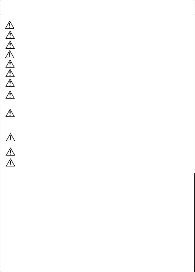
(1) Standard incremental system |
|
|
|
|
|
|
Unit name |
Type |
Qty. |
|
|
MDS-B-V14L |
|
Linear servomotor |
LM-NP - |
1 |
|
|
Servo driver |
|
|
|
|
|
|||
Servo driver |
MDS-B-V14L- |
1 |
|
|
|
|
Linear scale |
LS186, LIDA181 etc. |
1 |
|
|
|
|
Scale I/F unit |
MDS-B-HR-11M |
1 |
|
|
|
|
Pole detection unit |
MDS-B-MD-600 |
1 |
To NC or |
CN1A |
CN1B |
To next axis, |
|
|
|
terminator or |
|||
|
|
|
previous axis |
|
|
battery unit |
|
|
|
|
|
|
|
|
|
|
|
|
CN4 |
|
|
|
|
|
|
|
To power |
|
|
|
|
|
CN3 |
|
|
|
|
|
CN2 |
|
supply if final |
|
|
|
|
|
|
axis |
|
Motor thermal |
|
|
|
L+ |
|
|
|
|
|
L– |
||
|
signal |
|
|
|
|
|
|
|
|
|
|
Single-phase |
|
|
|
|
|
|
|
200VAC |
Pole detector |
|
|
Empty |
|
|
|
|
CON3 |
CON1 |
|
|
|
|
(MDS-B-MD-600) |
|
|
U V W |
|
||
|
|
|
|
|
|
|
|
|
|
|
|
|
|
|
|
|
|
|
|
|
|
|
|
|
|
|
|
|
|
|
|
|
|
|
|
|
|
|
|
|
|
|
|
|
Linear motor |
CON4 |
|
|
|
|
CON2 |
||||||||||||
primary side |
|
|
|
|
|
|
|
|
|
Scale I/F |
|
|||||||
|
|
|
|
|
|
|
|
|
|
|
|
|
||||||
|
|
|
|
|
|
|
|
|
(MDS-B-HR-11M) |
|
||||||||
|
|
|
|
|
|
|
|
|
|
|
|
|
|
|
|
|
|
|
|
|
|
|
|
|
|
|
|
|
|
|
|
|
|
|
|
|
|
|
|
|
|
|
|
|
|
|
|
|
|
|
|
|
|
|
|
|
 Analog voltage output type incremental scale (LS186,LIDA181,LIF181,etc.)
Linear motor secondary side permanent magnet
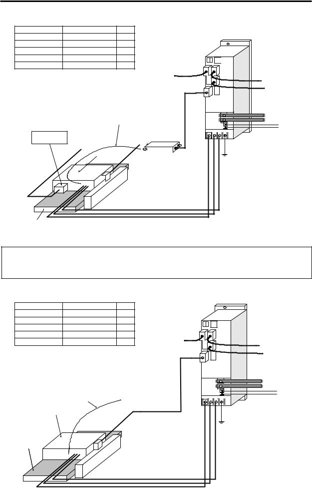
(2) Absolute system (System using linear scale LC191M)
In a system that does not use the MDS-B-HR unit (scale I/F unit), use the
CAUTION motor thermal signal for the CNC unit's general-purpose input port, and detect the motor overheating.
|
|
|
|
|
MDS-B-V14L |
|
|
Unit name |
Type |
Qty. |
|
|
Servo driver |
|
|
|
|
|
|
||||
Linear servomotor |
LM-NP - |
1 |
|
|
|
|
|
Servo driver |
MDS-B-V14L- |
1 |
|
|
|
|
|
Linear scale |
LC191M |
1 |
|
|
|
To next axis, |
|
Scale I/F unit |
None |
0 |
|
|
|
||
To NC or |
CN1A |
|
terminator or |
||||
Pole detection unit |
None |
0 |
|
CN1B |
battery unit |
||
previous axis |
|||||||
|
|||||||
|
|
|
|
|
CN4 |
|
|
|
|
|
|
|
CN3 |
To power |
|
|
|
|
|
CN2 |
|
supply if final |
|
|
|
|
|
|
axis |
||
|
|
|
|
|
|
||
|
|
|
|
|
|
L+ |
|
|
|
|
|
|
|
L– |
|
|
|
|
|
|
|
Single-phase |
|
|
Motor thermal |
To NC general- |
|
|
|
200VAC |
|
|
|
|
|
|
|||
|
signal |
purpose input port |
|
|
|
|
|
Linear motor |
|
|
|
U V W |
|
||
primary side |
|
|
|
|
|||
|
|
|
|
|
|||
Linear motor secondary side permanent magnet
LC191M (Heidenhain)
 Absolute position linear scale
2–6
Chapter 2 Drive System Configuration
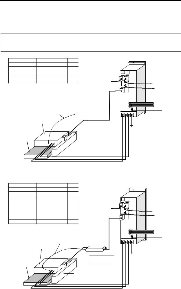
(3)Absolute system 2 (System using linear scale AT342)
The linear scale and servo drive unit can be connected directly and used without the scale I/F unit (MDS-B-HR) or pole detection unit (MDS-B-MD). Note that the position and speed resolution will be limited to 0.5µm, so to further improve the controllability, use of the system shown in (4) is recommended.
In a system that does not use the MDS-B-HR unit (scale I/F unit), use the
CAUTION motor thermal signal for the CNC unit's general-purpose input port, and detect the motor overheating.
|
|
|
|
|
|
MDS-B-V14L |
|
Unit name |
|
Type |
Qty. |
|
|
Servo driver |
|
|
|
|
|
|
|||
Linear servomotor |
LM-NP - |
1 |
|
|
|
|
|
Servo driver |
MDS-B-V14L- |
1 |
|
|
|
|
|
Linear scale |
AT342 |
|
1 |
|
|
|
To next axis, |
Scale I/F unit |
|
None |
0 |
|
|
|
|
|
To NC or |
CN1A |
CN1B |
terminator or |
|||
Pole detection unit |
|
None |
0 |
||||
|
|
|
battery unit |
||||
|
|
|
|
previous axis |
|
CN4 |
|
|
|
|
|
|
|
|
|
|
|
|
|
|
|
CN3 |
To power supply if |
|
|
|
|
|
CN2 |
|
|
|
|
|
|
|
|
final axis |
|
|
|
|
|
|
|
|
L+ |
|
|
|
To NC general- |
|
|
|
L– |
|
|
|
|
|
|
Single-phase |
|
|
|
Motor thermal |
purpose input port |
|
|
|
200VAC |
|
|
|
|
|
|
||
Linear motor |
signal |
|
|
|
|
|
|
|
|
|
|
U V W |
|
||
primary side |
|
|
|
|
|
||
Linear motor secondary side permanent magnet
AT342 (Mitsutoyo)  Absolute position
linear scale
(4)Absolute system 3 (System using linear scale AT342 special + MDS-B-HR-21)
By using the scale I/F unit (MDS-B-HR), the resolution of the position and speed used for servo control can be improved, thereby improving the servo's controllability.
|
|
|
|
|
|
MDS-B-V14L |
|
|
Unit name |
Type |
|
Qty. |
|
|
Servo driver |
|
|
Linear servomotor |
LM-NP - |
1 |
|
|
|
|
||
Servo driver |
MDS-B-V14L- |
1 |
|
|
|
|
||
Linear scale |
AT342 (Special) |
1 |
|
|
|
|
||
|
MDS-B-HR-21M |
|
|
|
|
To next axis, |
||
|
MDS-B-HR-21 can |
|
|
|
|
|||
|
|
|
CN1A |
CN1B |
terminator or |
|||
|
be used when |
|
To NC or |
|
||||
Scale I/F unit |
0 |
|
|
battery unit |
||||
detecting the motor |
previous axis |
CN4 |
||||||
|
|
|
||||||
|
thermal signal with |
|
|
|
|
|||
|
|
|
|
|
To power supply |
|||
|
the CNC. |
|
|
|
|
CN3 |
||
|
|
|
|
|
|
|
||
Pole detection unit |
None |
0 |
|
CN2 |
|
if final axis |
||
|
|
|
||||||
|
|
|
|
|
|
|
L+ |
|
|
|
|
|
|
|
|
L– |
|
|
|
|
|
|
|
|
Single-phase |
|
|
|
Motor thermal |
|
|
|
200VAC |
||
|
|
Empty |
|
|
|
|||
|
Linear motor |
signal |
CON3 |
|
|
|
||
|
|
CON1 |
|
U V W |
|
|||
|
primary side |
|
|
|
|
|
||
|
|
|
CON4 |
CON2 |
|
|
|
|
Linear motor |
|
|
Empty |
Scale I/F |
|
|
|
|
secondary side |
|
|
|
|
|
|||
|
|
(MDS-B-HR-21M) |
|
|
|
|||
permanent |
|
|
|
|
|
|
||
|
|
|
|
|
|
|
||
magnet |
|
|
|
|
|
|
|
|
|
|
|
AT342 special (Mitsutoyo) |
|
|
|
||
|
|
|
Absolute position linear scale |
|
|
|
||
2–7
Chapter 2 Drive System Configuration
2-3-2 Configuration of parallel drive system
The system configuration when driving one axis with two motors and two servo drive units is as shown below. In this case, the position command sent to each servo drive unit must be the same position command using the CNC synchronous control function.
(1) 2-scale 2-motor (2-amplifier) control
Incremental system |
Absolute system |
Unit name |
Type |
Qty. |
Linear servomotor |
LM-NP - |
2 |
Servo driver |
MDS-B-V14L- |
2 |
Linear scale |
LS186, LIDA181 etc. |
2 |
Scale I/F unit |
MDS-B-HR-12M |
1 |
|
|
|
|
MDS-B-HR-11M |
1 |
|
|
|
Pole detection unit |
MDS-B-MD-600 |
2 |
Unit name |
Type |
Qty. |
Linear servomotor |
LM-NP - |
2 |
Servo driver |
MDS-B-V14L- |
2 |
Linear scale |
AT342 (Special) |
2 |
Scale I/F unit |
MDS-B-HR-22M |
1 |
|
MDS-B-HR-22 can |
|
|
be used when |
|
|
detecting the motor |
|
|
thermal signal with |
|
|
the NC. |
|
|
MDS-B-HR-21M |
1 |
|
MDS-B-HR-21 can |
|
|
be used when |
|
|
detecting the motor |
|
|
thermal signal with |
|
|
the NC. |
|
Pole detection unit |
None |
0 |
|
|
|
|
|
|
|
|
|
|
Master axis |
Slave axis |
|
|
|
|
|
|
|
|
|
|
|
MDS-B-V14L MDS-B-V14L |
|
|
|
|
|
|
|
|
|
|
|
|
|
To next axis, |
|
|
|
|
|
|
|
|
|
|
|
|
|
|
|
|
|
Scale I/F |
|
|
To NC or |
CN1A |
|
CN1B |
CN1B |
terminator or |
|
|
|
|
|
|
|
|
|
|
|
battery unit |
||
|
|
|
(Incremental scale : MDS-B-HR-11M) |
previous axis |
|
|
|
|
|
|||
|
|
|
|
|
|
CN4 |
CN4 |
|
||||
|
|
|
(AT342 scale |
: MDS-B-HR-21M) |
|
|
|
|
|
|||
|
Motor thermal signal |
|
|
|
|
|
|
|
|
CN3 |
|
|
|
|
CON3 |
CON1 Empty |
|
|
|
|
|
|
CN3 |
To power supply |
|
|
|
|
|
|
CN2 |
|
|
|
||||
|
|
|
|
|
|
|
|
|
CN2 |
|
if final axis |
|
|
|
|
|
|
|
|
|
|
|
|
||
|
|
|
CON4 |
CON2 |
|
|
|
|
|
|
|
|
|
|
Linear motor |
|
|
|
|
|
|
|
|
L+ |
|
|
|
primary side |
Scale I/F |
|
|
|
|
|
|
|
L– |
|
|
|
(Slave) |
|
|
|
|
|
|
|
|
Single-phase |
|
|
|
Motor thermal |
(Incremental scale : MDS-B-HR-12M) |
|
|
|
|
|
||||
|
|
|
signal |
(AT342 scale |
: MDS-B-HR-22M) |
|
|
|
|
|
200VAC |
|
Pole detector |
|
|
|
|
|
|
|
|
||||
|
|
|
CON3 |
|
CON1 |
|
|
|
|
|
|
|
(MDS-B-MD-600) |
|
|
|
|
U |
V |
W |
U V |
W |
|
||
* Not required for the AT342 |
|
|
|
|
|
|
|
|||||
scale |
|
|
Linear motor |
|
|
|
|
|
|
|
|
|
|
|
|
CON4 |
|
CON2 |
|
|
|
|
|
|
|
|
|
primary side (Master) |
|
|
|
|
|
|
|
|||
|
|
|
|
|
|
|
|
|
|
|
||
|
Linear scale |
Analog voltage output type |
|
|
|
|
|
incremental scale or |
|
Pole detector |
AT342 (Mitsutoyo) |
|
(MDS-B-MD-600) |
absolute position scale |
Linear scale |
* Not required for the AT342 |
|
|
scale |
|
2–8

Chapter 2 Drive System Configuration
(2)1-scale 2-motor (2-amplifier) control
When using only one linear scale to detect the position, if this linear scale is an incremental scale, the pole position of each motor cannot be detected independently. Thus, the motor installation position on the master side and slave side must be mechanically aligned.
If the linear scale is an absolute position scale, the pole position of each motor can be set independently in the CNC as an absolute position even when only one linear scale is being used. However in this case, DC excitation must be carried out with only one motor, so this method is limited to when the axis can be driven with one motor (possible if low-speed drive) is possible.
Incremental system
Unit name |
Type |
Qty. |
Linear servomotor |
LM-NP - |
2 |
Servo driver |
MDS-B-V14L- |
2 |
Linear scale |
LS186, LIDA181 etc. |
1 |
Scale I/F unit |
MDS-B-HR-12M |
1 |
|
|
|
Pole detection unit |
MDS-B-MD-600 |
1 |
Absolute system
Unit name |
Type |
Qty. |
Linear servomotor |
LM-NP - |
2 |
Servo driver |
MDS-B-V14L- |
2 |
Linear scale |
AT342 (Special) |
1 |
Scale I/F unit |
MDS-B-HR-22M |
1 |
|
MDS-B-HR-22 can |
|
|
be used when |
|
|
detecting the motor |
|
|
thermal signal with |
|
|
the NC. |
|
Pole detection unit |
None |
0 |
Master axis |
|
Slave axis |
|
MDS-B-V14L MDS-B-V14L
|
|
|
To NC or |
|
|
|
To next axis, |
|
|
|
|
|
|
||
|
|
|
previous axis |
CN1A |
CN1B |
CN1B |
terminator or |
|
|
|
|
|
|
|
battery unit |
|
|
|
|
|
CN4 |
CN4 |
|
|
|
|
|
|
CN3 |
|
|
|
|
|
|
|
|
CN3 |
To power supply |
|
|
|
|
CN2 |
|
||
|
|
|
|
|
CN2 |
if final axis |
|
|
|
|
|
|
|
||
|
|
|
|
|
|
|
L+ |
|
|
Scale I/F |
|
|
|
|
L– |
|
|
|
|
|
|
Single-phase |
|
|
|
(Incremental scale : MDS-B-HR-12M) |
|
|
|
||
|
|
|
|
|
200VAC |
||
|
Motor thermal |
(AT342 scale |
: MDS-B-HR-22M) |
|
|
|
|
|
CON3 |
CON1 |
|
|
|
|
|
Linear motor |
signal |
|
|
|
U V W |
|
|
|
|
|
|
|
|
|
|
primary side |
|
CON4 |
CON2 |
|
|
|
|
(Slave) |
Linear motor primary |
|
|
|
|
||
|
side (Master) |
|
|
|
|
|
|
|
|
|
|
|
|
|
|
|
|
|
|
Linear scale |
|
|
|
|
|
|
|
|
|
|
|
|
|
|
|
|
Analog voltage output type |
|
|
|
|
|
|
|
|
|
|
|
|
|
|
incremental scale or |
|
|
|
|
|
|
|
|
|
|
|
|
|
|
|
|
|
|
|
|
|
|
|
|
|
|
|
Pole detector |
|
AT342 (Mitsutoyo) |
|
|
|
|
|
|
|
|
|
|
|
||||
|
|
|
|
|
|
|
|
|
|
|
|
(MDS-B-MD-600) |
|
absolute position scale |
|
|
|
|
|
|
|
|
|
||||||
|
|
|
|
|
|
|
|
|
|
|
|
* Not required for the AT342 |
|
|
|
|
|
|
|
|
|
|
|
|
|
|
scale |
|
|
|
|
|
|
|
|
|
|
|
|
|
|
|||
|
|
|
|
|
|
|
|
|
|
|
|
|
|
|
2–9

Chapter 3 Selection
3-1 |
Selecting the linear servomotor ................................................................. |
3-2 |
|
|
3-1-1 |
Max. feedrate....................................................................................... |
3-2 |
|
3-1-2 |
Max. thrust ........................................................................................... |
3-2 |
|
3-1-3 |
Continuous thrust................................................................................. |
3-4 |
3-2 |
Selecting the power supply unit................................................................. |
3-6 |
|
3-3 |
Selecting the power supply capacity, wire size, AC reactor, |
|
|
|
contactor and NFB ....................................................................................... |
3-6 |
|
3–1

Chapter 3 Selection
3-1 Selecting the linear servomotor
It is important to select a linear servomotor matched to the purpose of the machine that will be installed. If the linear servomotor and machine to be installed do not match, the motor performance cannot be fully realized, and it will also be difficult to adjust the parameters. Be sure to understand the linear servomotor characteristics in this chapter to select the correct motor.
3-1-1 Max. feedrate
The max. feedrate for the LM-N Series linear servomotor is 120m/min. However, there are systems that cannot reach the max. speed 120m/min depending on the linear scale being used. Refer to the section "2-3-1 Standard linear servo system) for the main systems and possible max. feedrates.
3-1-2 Max. thrust
The linear servomotor has an output range for the continuous thrust that can be used only for short times such as acceleration/deceleration. If the motor is a self-cooling type, a thrust that is approx. 6-fold can be output. For an oil-type motor, a thrust that is approx. 3-fold can be output.
The max. linear motor thrust required for acceleration/deceleration can be approximated using the machine specifications and expression (3-1).
Fmax = (M • a + Ff) • 1.2 |
(3-1) |
|
Fmax : Max. motor thrust |
(N) |
|
M |
: Movable mass (including motor's moving sections) |
(kg) |
a |
: Acceleration during acceleration/deceleration |
(m/s2) |
Ff |
: Load force (including cutting force, wear and unbalance force) (N) |
|
Note that there is a servo response delay as shown on the right in respect to the acceleration in the acceleration/ deceleration command set with the CNC. Thus, the acceleration characteristics (thrust characteristics required for acceleration/deceleration when movable mass is applied) in respect to the speed required for the linear servomotor will be as shown on the next page. (Conditions: Indicates the characteristics using the position loop gain during SHG control using a linear acceleration/deceleration command pattern.) Thus, when selecting the linear motor, refer to the speed - acceleration (thrust) characteristics on the next page, and confirm the speed - thrust characteristics (4-4 Torque characteristics drawing) for the linear motor.
Speed |
Command |
speed |
Servo response |
Time |
(Note) The speed – acceleration characteristics on the next page are reference values at a specific condition, so if an S-character acceleration/deceleration filter is applied on the command, if the position loop gain differs, the characteristics will also differ.
3–2

Chapter 3 Selection
During acceleration: Speed – acceleration acceleration
Servo response characteristics
Max. speed 120m/min, PGN1 = 47 (SHG)
40


 During
35 acceleration
|
30 |
|
Command 29.4m/s2 |
|
|
||
(m/s2) |
|
|
|
|
|
|
|
25 |
|
|
|
|
|
|
|
|
|
Command 19.6m/s2 |
|
|
|||
Acceleration |
20 |
|
|
|
|||
|
|
|
|
|
|
||
15 |
|
|
|
|
|
|
|
|
|
Command 9.8m/s2 |
|
|
|||
|
10 |
|
|
|
|||
|
|
|
|
|
|
|
|
|
5 |
|
|
|
|
|
|
|
00 |
20 |
40 |
60 |
80 |
100 |
120 |
Velocity (m/min)
Max. speed 80m/min, PGN1 = 47 (SHG) |
|||||||
|
40 |
During |
|
|
|
|
|
|
35 |
acceleration |
|
|
|
|
|
|
30 |
Command 29.4m/s2 |
|
|
|
||
(m/s2) |
|
|
|
|
|
|
|
25 |
|
|
|
|
|
|
|
|
Command 19.6m/s2 |
|
|
|
|||
Acceleration |
20 |
|
|
|
|||
|
|
|
|
|
|
||
15 |
|
|
|
|
|
|
|
|
Command 9.8m/s2 |
|
|
|
|||
|
10 |
|
|
|
|||
|
|
|
|
|
|
|
|
|
5 |
|
|
|
|
|
|
|
00 |
20 |
40 |
60 |
80 |
100 |
120 |
|
|
|
|
Velocity (m/min) |
|
|
|
Max. speed 120m/min, PGN1 = 100 (SHG)
40
 During
35 acceleration
|
30 |
|
Command 29.4m/s2 |
|
|
||
(m/s2) |
|
|
|
|
|
|
|
25 |
|
|
|
|
|
|
|
|
|
Command 19.6m/s2 |
|
|
|||
Acceleration |
20 |
|
|
|
|||
|
|
|
|
|
|
||
15 |
|
|
|
|
|
|
|
|
|
Command 9.8m/s2 |
|
|
|||
|
10 |
|
|
|
|||
|
|
|
|
|
|
|
|
|
5 |
|
|
|
|
|
|
|
00 |
20 |
40 |
60 |
80 |
100 |
120 |
Velocity (m/min)
Max. speed 80m/min, PGN1 = 100 (SHG)
40


 During
35 acceleration
(m/s2) |
30 |
Command 29.4m/s2 |
|
|
|
||
25 |
|
|
|
|
|
|
|
|
Command 19.6m/s2 |
|
|
|
|||
Acceleration |
20 |
|
|
|
|||
|
|
|
|
|
|
||
15 |
|
|
|
|
|
|
|
|
Command 9.8m/s2 |
|
|
|
|||
|
10 |
|
|
|
|||
|
|
|
|
|
|
|
|
|
5 |
|
|
|
|
|
|
|
00 |
20 |
40 |
60 |
80 |
100 |
120 |
Velocity (m/min)
During deceleration: Speed –
Servo response characteristics
Max. speed 120m/min, PGN1 = 47 (SHG)
40


 During
35 decceleration
|
30 |
|
Command 29.4m/s2 |
|
|
||
(m/s2) |
|
|
|
|
|
|
|
25 |
|
|
|
|
|
|
|
|
|
Command 19.6m/s2 |
|
|
|||
Acceleration |
20 |
|
|
|
|||
|
|
|
|
|
|
||
15 |
|
|
|
|
|
|
|
|
|
Command 9.8m/s2 |
|
|
|||
|
10 |
|
|
|
|||
|
|
|
|
|
|
|
|
|
5 |
|
|
|
|
|
|
|
00 |
20 |
40 |
60 |
80 |
100 |
120 |
Velocity (m/min)
Max. speed 80m/min, PGN1 = 47 (SHG) |
|||||||
|
40 |
|
|
|
|
|
|
|
35 |
During |
|
|
|
|
|
|
decceleration |
Command 29.4m/s2 |
|
|
|||
|
30 |
|
|
|
|||
(m/s2) |
|
|
|
|
|
|
|
25 |
|
|
|
|
|
|
|
|
Command 19.6m/s2 |
|
|
|
|||
Acceleration |
20 |
|
|
|
|||
|
|
|
|
|
|
||
15 |
|
|
|
|
|
|
|
|
Command 9.8m/s2 |
|
|
|
|||
|
10 |
|
|
|
|||
|
|
|
|
|
|
|
|
|
5 |
|
|
|
|
|
|
|
00 |
20 |
40 |
60 |
80 |
100 |
120 |
Velocity (m/min)
Max. speed 120m/min, PGN1 = 100 (SHG)
40


 During
35 acceleration
|
30 |
|
Command 29.4m/s2 |
|
|
||
(m/s2) |
|
|
|
|
|
|
|
25 |
|
|
|
|
|
|
|
|
|
|
|
|
|
|
|
Acceleration |
20 |
|
Command 19.6m/s2 |
|
|
||
|
|
|
|
|
|
||
15 |
|
|
|
|
|
|
|
|
|
Command 9.8m/s2 |
|
|
|||
|
10 |
|
|
|
|||
|
|
|
|
|
|
|
|
|
5 |
|
|
|
|
|
|
|
00 |
20 |
40 |
60 |
80 |
100 |
120 |
Velocity (m/min)
Max. speed 80m/min, PGN1 = 100 (SHG) |
|||||||
|
40 |
|
|
|
|
|
|
|
35 |
During |
|
|
|
|
|
|
decceleration |
|
|
|
|
|
|
(m/s2) |
30 |
Command 29.4m/s2 |
|
|
|
||
25 |
|
|
|
|
|
|
|
|
Command 19.6m/s2 |
|
|
|
|||
Acceleration |
20 |
|
|
|
|||
|
|
|
|
|
|
||
15 |
|
|
|
|
|
|
|
|
Command 9.8m/s2 |
|
|
|
|||
|
10 |
|
|
|
|||
|
|
|
|
|
|
|
|
|
5 |
|
|
|
|
|
|
|
00 |
20 |
40 |
60 |
80 |
100 |
120 |
Velocity (m/min)
3–3

Chapter 3 Selection
3-1-3 Continuous thrust
A typical operation pattern is assumed, and the motor's continuous effective load thrust (Frms) is calculated from the load force. If numbers (1) to (8) in the following drawing were considered a one cycle operation pattern, the continuous effective load thrust is obtained from the root mean square of the thrust during each operation, as shown in the expression (3-2).
|
(1) |
(2) |
(3) |
(4) |
(5) |
(6) |
(7) |
(8) |
Motor |
0 |
|
|
|
|
|
|
|
speed |
|
|
|
|
|
|
|
|
|
F1 |
|
|
|
|
|
F7 |
|
|
|
|
|
F4 |
|
|
|
|
Motor |
|
F2 |
|
|
|
|
|
|
0 |
|
|
|
|
|
|
|
|
thrust |
|
F3 |
|
|
F6 |
|
Time |
|
|
|
|
|
|
|
|||
|
|
|
|
F5 |
|
F8 |
||
|
|
|
|
|
|
|
|
|
|
t1 |
t2 |
t3 |
t4 |
t5 |
t6 |
t7 |
t8 |
|
|
|
|
|
t0 |
|
|
|
Fig. 3-1 Continuous operation pattern
Frms = |
F12·t1 + F22·t2 + F32·t3 + F42·t4 + F52·t5 + F62·t6 + F72·t7 + F82·t8 |
(3-2) |
|
t0 |
|
Select a motor so that the continuous effective load thrust (Frms) is 80% or less of the motor rated thrust (Fs).
Frms ≤ 0.8 × Fs |
(3-3) |
(1)Horizontal axis load thrust
When operations (1) to (8) are for a horizontal axis, calculate so that the following thrusts are required in each period.
Table 3-1 Load thrusts of horizontal axes
Period |
Load thrust calculation method |
Explanation |
|
|
(Amount of acceleration thrust) + (Kinetic |
Normally the acceleration/deceleration time constant is |
|
(1) |
calculated so this thrust is 80% of the maximum thrust of |
||
friction force) |
|||
|
the motor. |
||
|
|
||
(2) |
(Kinetic friction force) + (Cutting force) |
|
|
|
(Amount of deceleration thrust) + |
The signs for the amount of acceleration thrust and |
|
(3) |
amount of deceleration thrust are reversed when the |
||
(Kinetic friction force) |
|||
|
absolute value is the same value. |
||
|
|
||
(4) |
(Static friction force) |
Calculate so that the static friction force is always required |
|
during a stop. |
|||
|
|
||
(5) |
− (Amount of acceleration thrust) − |
The signs are reversed with period (1) when the kinetic |
|
(Kinetic friction force) |
friction does not change according to movement direction. |
||
|
|||
(6) |
− (Kinetic friction force) − (Cutting force) |
The signs are reversed with period (2) when the kinetic |
|
friction does not change according to movement direction. |
|||
|
|
||
(7) |
− (Amount of deceleration thrust) − |
The signs are reversed with period (3) when the kinetic |
|
(Kinetic friction force) |
friction does not change according to movement direction. |
||
|
|||
(8) |
− (Static friction force) |
Calculate so that the static friction force is always required |
|
during a stop. |
|||
|
|
3–4
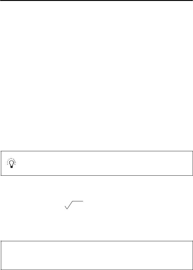
Chapter 3 Selection
(2)Unbalance axis load force
When operations (1) to (8) are for an unbalance axis, calculate so that the following forces are required in each period. Note that the forward speed shall be an upward movement.
Table 3-2 Load thrusts of unbalance axes
Period |
Load thrust calculation method |
Explanation |
|
|
(Amount of acceleration thrust) + |
Normally the acceleration/deceleration time constant is |
|
(1) |
(Kinetic friction force) + (Unbalance |
calculated so this thrust is 80% of the maximum thrust of the |
|
|
force) |
motor. |
|
(2) |
(Kinetic friction force) + (Unbalance |
|
|
force) + (Cutting force) |
|
||
|
|
||
|
(Amount of deceleration thrust) + |
The signs for the amount of acceleration thrust and amount of |
|
(3) |
(Kinetic friction force) + (Unbalance |
deceleration thrust are reversed when the absolute value is |
|
|
thrust) |
the same value. |
|
(4) |
(Static friction force) + (Unbalance |
The holding force during a stop becomes fairly large. |
|
force) |
(Upward stop) |
||
|
|||
(5) |
− (Amount of acceleration thrust) − |
|
|
(Kinetic friction force) + (Unbalance |
|
||
|
force) |
|
|
(6) |
− (Kinetic friction force) + (Unbalance |
The generated force may be in the reverse of the movement |
|
force) − (Cutting force) |
direction, depending on the size of the unbalance force. |
||
|
|||
(7) |
− (Amount of deceleration thrust) − |
|
|
(Kinetic friction force) + (Unbalance |
|
||
|
force) |
|
|
(8) |
− (Static friction force) + (Unbalance |
The holding force becomes smaller than the upward stop. |
|
force) |
(Downward stop) |
||
|
During a stop, the static friction force may constantly be applied. The static friction force and unbalance force may particularly become larger during an POINT unbalance upward stop, and the thrust during a stop may become extremely
large. Therefore, caution is advised.
(3)Max. cutting thrust and max. cutting duty
If the max. cutting force and max. cutting duty (%/min) are known, the following expression can be used for the selection conditions.
0.8 × Fs ≥ Fc × |
D |
|
|
100 |
|
(3-4) |
|
|
|
||
Fs : Motor continuous thrust |
(N) |
||
Fc : Max. cutting force during operation |
(N) |
||
D : Max. cutting duty |
(%/min) |
||
(4) Unbalance force
For an unbalanced axis, such as a gravity axis, basically balance it with a device such as a counterbalance. With the linear motor, the continuous thrust
CAUTION is lower than the rotary motor, so if the axis is unbalanced the motor's heating amount will increase. If an error should occur, the axis will drop naturally. This
is hazardous as the dropping distance and dropping speed are large.
3–5

Chapter 3 Selection
3-2 Selecting the power supply unit
Compared to the normal rotary motor, when using the linear servo system, the instantaneous output, such as the acceleration/deceleration, is large in respect to the continuous operation. Furthermore, this system is used in applications where acceleration/deceleration is carried out frequently, so the selection differs from the methods for selecting the conventional power supply unit.
Power supply unit capacity >Σ (Spindle motor output) |
|
+Σ (Capacity of servo amplifier driving linear motor) |
|
+0.7 × Σ (Rotary servomotor output) |
(3-5) |
*When using two or more axes with the rotation motor
Select a power supply unit capacity having the minimum lineup capacity that satisfies expression (3-5).
(Caution) With the linear servo axis, this is used for an axis with a high acceleration/deceleration frequency compared to that multiplied by 0.7 when using two or more axes with the rotation motor, so the value does not need to be multiplied by 0.7.
POINT |
Refer to the "MELDAS AC Servo and Spindle MDS-A Series, MDS-B Series |
Specifications BNP-B3759B" for other details on the power supply unit. |
3-3 Selecting the power supply capacity, wire size, AC reactor, contactor and NFB
The selection of the power supply capacity, wire size, AC reactor, contactor
and NFB is the same as the MDS-B-V1 unit.
POINT Refer to the "MELDAS AC Servo and Spindle MDS-A Series, MDS-B Series Specifications BNP-B3759B".
3–6

Chapter 4 Linear Servomotor Specifications
4-1 |
Type configuration....................................................................................... |
4-2 |
4-2 |
List of specifications ................................................................................... |
4-3 |
4-3 Speed – torque characteristics drawing (At input voltage 200VAC) ....... |
4-4 |
|
4-4 |
Dynamic brake characteristics ................................................................... |
4-5 |
4-5 |
Outline dimensions ..................................................................................... |
4-6 |
4-6 |
Explanation of connectors.......................................................................... |
4-9 |
4–1

Chapter 4 Linear Servomotor Specifications
4-1 Type configuration
The type indication for the linear servomotor differs for the primary side and secondary side.
(1) Primary side
LM – N |
P |
|
1) |
|
|
2) |
– |
3) |
|
4) |
– |
5) |
||
|
|
|
|
|
|
|
|
|
|
|
|
|
|
|
1) Width dimensions |
|
|
|
|
||||||||||
|
(nominal dimensions) |
|
|
|
|
|
||||||||
2 |
|
130 |
[mm] |
|
|
|
|
|||||||
4210 [mm]
1)Length dimensions (nominal dimensions)
S |
290 [mm] |
M |
530 [mm] |
L |
770 [mm] |
G1,010 [mm]
(2)Secondary side
5) Mitsubishi control No.
The Mitsubishi control No. is indicated with two alphanumeric digits.
4) Max. speed
M120 [m/s]
3)Rated thrust
The rated thrust is indicated with the two digits for the 1000th place and 100th place.
Example) 500[N]→05 3,000[N]→30
LM – N |
S |
|
1) |
|
0 |
– |
2) |
– |
3) |
||
|
|
|
|
|
|
|
|
|
|
|
|
1) Width dimensions |
|
|
|
|
|
|
|||||
|
(nominal dimensions) |
|
|
|
|||||||
|
|
|
|
|
|
|
|
||||
|
2 |
|
|
120 [mm] |
|
|
|
||||
|
4 |
|
|
210 [mm] |
|
|
|
||||
|
|
|
|
|
|
|
|
|
|
|
|
|
|
|
|
|
|
|
|
|
|
|
|
5) Mitsubishi control No.
The Mitsubishi control No. is indicated with two alphanumeric digits.
2) Length dimensions (nominal dimensions)
The secondary side length dimensions are indicated as a [mm] unit with three digits.
Example) 360[mm]→360
|
The combination of the primary side and secondary side is indicated with the |
CAUTION |
type symbol 1). |
Select a model that has the same type symbol 1) for the primary side and |
|
|
secondary side. |
|
|
4–2
 Loading...