


 Loading...
CNC
AC SPINDLE
MDS-B-SPJ2 Series
SPECIFICATION MANUAL
BNP-B2164A(ENG)

Thank you for purchasing the Mitsubishi AC spindle drive unit. This manual describes the handling and precautions for using this unit. Incorrect handling may lead to unforeseen accidents, so always read this manual thoroughly to ensure correct usage.
Make sure that this manual is delivered to the end user. Always store this manual for future reference.
All specifications of the MDS-B-SPJ2 Series are listed in this manual. However, each CNC does not always apply to the specifications, so confirm the CNC specifications before using the unit.
Precautions for reading this Specifications and Maintenance Manual
(1)This manual gives a general explanation for the spindle system. Refer to the manuals issued by the machine maker for the specifications of each machine tool.
The "restrictions" and "available functions" described in the manuals issued by the machine maker has precedence to those in this manual.
(2)This manual describes as many special operations as possible, but it should be interpreted that items not mentioned in this manual cannot be performed.
Precautions for Safety
Please read this manual and enclosed documents before starting installation, operation, maintenance or inspection to ensure correct usage. Thoroughly understand the device, safety information and precautions before starting operation. After reading, always store this manual where it can be accessed easily.
The safety precautions are ranked as "DANGER" and "CAUTION" in this instruction manual.
!DANGER

 CAUTION
When a dangerous situation may occur if handling is mistaken leading to fatal or major injuries.
When a dangerous situation may occur if handling is mistaken leading to medium or minor injuries, or physical damage.
Note that some items described as  CAUTION may lead to serious results depending on the situation. In any case, important information that must be observed is described.
Thank you for purchasing the Mitsubishi AC spindle drive.
The "Prohibited" and "Mandatory" displays are explained as follows.
: This indicates a prohibited action (an action that must not be done). For example, the
display for "Fire Prohibited" is  .
.
: This indicates a mandatory action (an action that must be done). For example, the display for grounding is  .
.
After reading, always store this manual where it can be accessed easily.
Precautions that do not reach the level of material damage and precautions for separate functions, etc., are ranked as "Note", "Notice" and "Memo".
Note : This indicates situations in which mishandling will result in failure of this product, but not material damage.
Notice : This indicates situations in which a separate function is entered by parameter change, etc., and other usage methods are required.
Memo : This indicates a point important for correct usage.

For Safe Use
1. Electric shock prevention
! DANGER
Always turn the power OFF and wait 10 minutes or more until the charge lamp has turned OFF before wiring or carrying out inspections. Using a tester, etc., always confirm that there is no voltage between the P-N terminals before starting wiring or inspections. Failure to observe this could lead to electric shocks.
Ground the spindle amplifier and spindle motor with Class 3 grounding or higher. Wiring and inspections must always be carried out by a qualified technician.
Always install the spindle amplifier and spindle motor before wiring. Failure to observe this could lead to electric shocks.
Do not touch the switches with wet hands. Failure to observe this could lead to electric shocks.
Do not damage, apply forcible stress, place heavy items or engage the cable. Failure to observe this could lead to electric shocks.
2. Fire prevention
 CAUTION
Install the spindle amplifier, spindle motor and regenerative resistor on noncombustible material. Direct installation on combustible material or near combustible materials could lead to fires.
Shut off the power on the spindle amplifier side if a fault occurs in the spindle amplifier. Fires could be caused if a large current continues to flow.
Shut off the power with an error signal when using the regenerative resistor. The regenerative resistor could abnormally overheat and cause a fire due to a fault in the regenerative transistor, etc.
3. Injury prevention
 CAUTION
Do not apply a voltage other than that specified in the Specifications or Instruction Manual on each terminal. Failure to observe this item could lead to ruptures or damage, etc.
Do not mistake the terminal connections. Failure to observe this item could lead to ruptures or damage, etc.
Do not mistake the DC voltage polarity (+, –). Failure to observe this item could lead to ruptures or damage, etc.
Do not touch the spindle amplifier fins, regenerative resistor or spindle motor, etc., while the power is turned ON or immediately after turning the power OFF. Some parts are heated to high temperatures, and touching these could lead to burns.

4. Various precautions
Observe the following precautions. Incorrect handling of the unit could lead to faults, injuries and electric shocks, etc.
(1) Transportation and installation
 CAUTION
Correctly transport the product according to its weight.
Do not stack the spindle motor or spindle amplifiers above the tolerable number. Do not hold the cables, axis or detector when transporting the spindle motor.
Do not hold the front cover when transporting the spindle amplifier. The unit could drop. Follow the Instruction Manual and install the unit in a place where the weight can be borne. Do not get on top of or place heavy objects on the product.
Always observe the installation direction.
 Secure the specified space between the spindle amplifier and inside wall of the control panel, and between other devices.
 Do not install or operate a spindle amplifier or spindle motor that is damaged or missing parts.
 Do not let conductive objects such as screws or metal chips, etc., or combustible materials such as oil enter the spindle amplifier or spindle motor.
 The spindle amplifier and spindle motor are precision devices, so do not drop them or apply strong impacts to them.
 Store and use the units under the following environment conditions.
Environment |
Conditions |
|
|
||
Spindle amplifier |
|
Spindle motor |
|||
|
|
||||
Ambient temperature |
0°C to +55°C (with no freezing) |
0°C to +40°C (with no freezing) |
|||
Ambient humidity |
90% RH or less |
80%RH or less |
|||
(with no dew condensation) |
(with no dew condensation) |
||||
|
|||||
Storage temperature |
–20°C to +65°C (with no freezing) |
–15°C to +70°C (with no freezing) |
|||
Storage humidity |
90%RH or less (with no dew condensation) |
||||
Atmosphere |
Indoors (Where unit is not subject to direct sunlight) |
||||
With no corrosive gas, combustible gas, oil mist or dust |
|||||
|
|||||
Altitude |
1000m or less above sea level |
|
|
|
|
Vibration |
5.9 m/s2 (0.6G) or less |
SJ-P, SJ-PF |
|
14.7 m/s2 (1.5G) or less |
|
 Securely fix the spindle motor to the machine. The spindle motor could come off during operation if insecurely fixed.
 Always install a cover, etc., over the shaft so that the rotary sections of the spindle motor cannot be touched during spindle motor rotation.
 When using a coupling connection to the spindle motor shaft, do not apply an impact by hammering, etc. The detector could be damaged.
 Do not apply a load exceeding the tolerable load onto the spindle motor shaft. The shaft could be damaged.
Before using this product after a long period of storage, please contact the Mitsubishi Service Station or Service Center.
(2) Wiring
 CAUTION
 Correctly and securely perform the wiring. Failure to do so could lead to runaway of the spindle motor.
 Do not install a phase advancing capacity, surge absorber or radio noise filter (option FR-BIF) on the output side of the spindle amplifier.
 Correctly connect the output side (terminals U, V, W). Failure to do so could lead to abnormal operation of the spindle motor.
 Do not directly connect a commercial power supply to the spindle motor. Doing so could lead to faults.
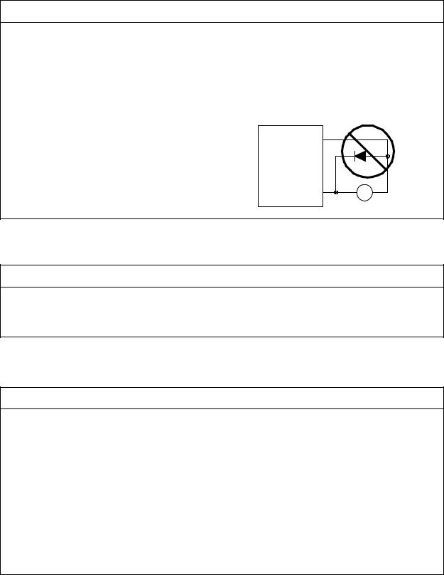
 Do not mistake the orientation of the surge absorption diode to be installed on
the DC relay for contactor and motor RA break output signals.
(3) Trial operation and adjustment
 CAUTION
 Check each parameter before starting operation. Failure to do so could lead to unforeseen operation of the machine.
 Do not make remarkable adjustments and changes as the operation could become unstable.
(4) Usage methods
 CAUTION
 Install an external emergency stop circuit so that the operation can be stopped immediately and the power can be shut off.
 Never disassemble or repair the unit.
 The operation will suddenly restart if a reset (RST) is carried out while an operation start signal (ST) is being input. Therefore, always confirm that the operation signal is OFF before resetting (RST). Failure to observe this could result in accidents.
 Never make modifications.
 Reduce the influence of electromagnetic interference by using a noise filter, etc. The electronic devices used near the spindle amplifier could be affected by magnetic noise.
 Use the spindle motor and spindle amplifier with the designated combination.
  Install a stop device for ensuring safety on the machine side.

(5) Troubleshooting
 CAUTION
 If a dangerous situation is predicted during a stop or product fault, take prevention measures by installing an external brake mechanism to hold the tool.
 When an alarm occurs, always eliminate the cause of the alarm and ensure safe operation before resetting.
 Never go near the machine after restoring the power after a failure, as the machine could start suddenly. (Design the machine so that personal safety can be ensured even if the machine starts suddenly.)
(6) Maintenance, inspection and part replacement
 CAUTION
 The capacity of the electrolytic capacitor will drop due to deterioration. To prevent secondary damage due to faults, replace the capacitor every ten years when using under a general environment. Consult the Service Station or Service Center for replacements.
(7) Disposal
 CAUTION
 Treat this unit as general industrial waste.
(8) General precautions
 CAUTION
The drawings given in this Specification Manual show the covers, safety partitions, etc., removed to provide a clearer explanation. Always return the covers and safety partitions to their specified locations before operating this product, and operate following the Instruction Manual.

Compliance to European EC Directives
1. European EC Directives
The European EC Directives were issued to unify Standards within the EU Community and to smooth the distribution of products of which the safety is guaranteed. In the EU Community, the attachment of a CE mark (CE marking) to the product being sold is mandatory to indicate that the basic safety conditions of the Machine Directives (issued Jan. 1995), EMC Directives (issued Jan. 1996) and the Low-voltage Directives (issued Jan. 1997) are satisfied. The machines and devices in which the servo and spindle are assembled are a target for CE marking.
The spindle is a component designed not to function as a single unit but to be used with a combination of machines and devices. Thus, it is not subject to the EMC Directives, and instead the machines and devices in which the spindle is assembled are targeted.
This spindle complies with the Standards related to the Low-voltage Directives in order to make CE marking of the assembled machines and devices easier. The EMC INSTALLATION GUIDELINES (BNP-B8582-45) which explain the spindle amplifier installation method and control panel manufacturing method, etc., has been prepared to make compliance to the EMC Directives easier. Contact Mitsubishi or your dealer for more information.
2. Cautions of compliance
Use the standard spindle amplifier and EN Standards compliance part for the spindle motor. In addition to the items described in this instruction manual, observe the items described below.
(1)Environment
The spindle amplifier must be used within an environment having a Pollution Class of 2 or more as stipulated in the IEC664. For this, install the spindle amplifier in a control panel having a structure (IP54) into which water, oil, carbon and dust cannot enter.
(2)Power supply
The spindle amplifier must be used with the overvoltage category II conditions stipulated in IEC664. For this, prepare a reinforced insulated transformer that is IEC or EN Standards complying at the power input section.
When supplying the interface power supply from an external source, use a 24 VDC power supply of which the input and output have been reinforced insulated.
(3)Installation
To prevent electric shocks, always connect the spindle amplifier protective earth (PE) terminal (terminal with  mark) to the protective earth (PE) on the control panel.
When connecting the earthing wire to the protective earth (PE) terminal, do not tighten the wire terminals together. Always connect one wire to one terminal.
PE terminal
(4)Wiring
Always use solderless terminals with insulation tubes so that the wires connected to the spindle amplifier terminal block do not contact the neighboring terminals.
PE terminal
Solderless terminal
Insulation tube
Wire
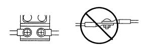
Connect the SJ-P and SJ-PF Series spindle motor power lead to the spindle amplifier using a fixed terminal block. Do not connect the wires directly.
(5) Peripheral devices and options
Use a no-fuse breaker and magnetic contactor that comply with the EN/IEC Standards described in section 6-2-1.
The wires sizes must follow the conditions below. When using other conditions, follow Table 5 of EN60204 and the Appendix C.
•Ambient temperature: 40°C
•Sheath: PVC (polyvinyl chloride)
•Install on wall or open table tray
When using the EMC filter, the radio noise filter (FR-BIF) is not required.
(6)Spindle motor
Contact Mitsubishi for the outline dimensions, connector signal array and detector cable.
(7)Others
Refer to the EMC INSTALLATION GUIDELINES (BNP-B8582-45) for other EMC Directive measures related to the spindle amplifier.
Contents
1. Outline ......................................................................................................................... |
1 - 1 |
|
1.1 |
Features for MDS-B-SPJ2 Series ......................................................................... |
1 - 1 |
1.2 |
Precautions for use ................................................................................................ |
1 - 1 |
1.3 |
Type configuration ................................................................................................. |
1 - 2 |
1.4 |
Basic functions and option functions ..................................................................... |
1 - 3 |
1.5 |
Configuration ......................................................................................................... |
1 - 4 |
1.5.1 Basic configuration ......................................................................................... |
1 - 4 |
|
1.5.2 Encoder orientation (full closed) .................................................................... |
1 - 8 |
|
2. Specifications ................................................................................................................ |
2 - 1 |
||
2.1 |
AC spindle motor and drive unit specifications ..................................................... |
2 - 1 |
|
2.2 |
Output characteristics ............................................................................................ |
2 - 3 |
|
2.3 |
Tolerable acceleration/deceleration frequency characteristics ............................. |
2 - 4 |
|
2.3.1 Frequency according to acceleration/deceleration time (tolerable duty cycle) |
2 - 4 |
||
2.3.2 Frequency according to regenerative resistor (tolerable duty cycle) ............ |
2 - 4 |
||
2.3.3 Combination of regenerative resistor capacity and unit ................................ |
2 - 5 |
||
2.4 |
Outline dimension .................................................................................................. |
2 - 6 |
|
2.4.1 |
Spindle drive unit ........................................................................................... |
2 - 6 |
|
2.4.2 |
Spindle motor ................................................................................................. |
2 - 10 |
|
2.4.3 |
Regenerative resistor ..................................................................................... |
2 - 17 |
|
3. Functions ....................................................................................................................... |
3 - 1 |
|
3.1 |
Control input signals .............................................................................................. |
3 - 1 |
3.2 |
Control output signals ............................................................................................ |
3 - 3 |
3.3 |
Meter output specifications .................................................................................... |
3 - 6 |
4. Handling ......................................................................................................................... |
4 - 1 |
|
4.1 |
Explanation of unit parts ........................................................................................ |
4 - 1 |
4.2 |
Installation .............................................................................................................. |
4 - 2 |
4.2.1 Spindle amplifier installation ............................................................................ |
4 - 2 |
|
4.3 |
Spindle drive unit heat radiation ............................................................................ |
4 - 4 |
5. Connections ................................................................................................................... |
5 - 1 |
|
5.1 |
Machine-to-machine connection diagram ............................................................. |
5 - 1 |
5.2 |
Spindle amplifier connections ................................................................................ |
5 - 3 |
5.2.1 Main circuit terminal block and control circuit terminal block .......................... |
5 - 3 |
|
5.2.2Signal names and applications of the main circuit terminal block and
|
control circuit terminal block ............................................................................ |
5 - 5 |
5.2.3 Usage method of the control circuit terminal block (MDS-B-SPJ2-02 to 075) |
5 - 6 |
|
5.3 Spindle motor and detector connection ................................................................. |
5 - 7 |
|
5.3.1 |
SJ-P0.2A/0.4A motor connection .................................................................... |
5 - 7 |
5.3.2 |
SJ-P0.75A motor connection........................................................................... |
5 - 7 |
5.3.3 |
SJ-P1.5A/2.2A/3.7A motor connection............................................................ |
5 - 8 |
5.3.4 SJ-PF Series motor connection (1.5/2.2/3.7kW)............................................. |
5 - 8 |
|
5.3.5 |
SJ-PF Series motor connection (5.5/7.5kW)................................................... |
5 - 9 |
5.3.6 |
SJ-PF Series motor connection (11kW).......................................................... |
5 - 10 |
5.4 Power supply connection ........................................................................................ |
5 - 11 |
|
5.4.1Connection example when controlling the electromagnetic switch
with an external sequence circuit .................................................................... |
5 - 11 |
5.4.2Connection example when controlling the electromagnetic switch
with the MDS-B-SPJ2...................................................................................... |
5 - 12 |
5.4.3Connection example when controlling the electromagnetic switch
|
with the MDS-B-CV/CR ................................................................................... |
5 - 13 |
5.4.4 Output circuit of the electromagnetic switch control signal (MCON )............. |
5 - 13 |
|
5.5 |
Regenerative resistor connection............................................................................ |
5 - 14 |
5.6 |
Relation to the main circuit .................................................................................... |
5 - 15 |
5.6.1Selection of the main circuit wire, no-fuse breaker and electromagnetic
|
|
contactor .......................................................................................................... |
5 - 15 |
5.6.2 |
Input/output DIO relay...................................................................................... |
5 - 15 |
|
5.7 |
Control circuit cables and connectors ..................................................................... |
5 - 16 |
|
6. Status Display and Parameter Setting .......................................................................... |
6 - 1 |
||
6.1 |
Status display with 7-segment LED ........................................................................ |
6 - 1 |
|
6.2 |
Spindle parameters ................................................................................................. |
6 - 2 |
|
6.3 |
SPINDLE SPECIFICATION PARAMETERS screen.............................................. |
6 - 16 |
|
6.4 |
SPINDLE MONITOR screen................................................................................... |
6 - 17 |
|
6.5 |
D/A output specifications......................................................................................... |
6 - 21 |
|
6.6 |
List of spindle protection functions and warning functions ..................................... |
6 - 26 |
|
7. Optional Specifications and Parts ................................................................................. |
7 - 1 |
||
7.1 |
Orient specifications (optional)................................................................................ |
7 - 1 |
|
7.1.1 4096 point orientation using encoder............................................................. |
7 - 1 |
||
7.1.2 4096 point orientation using motor built-in encoder ...................................... |
7 - 4 |
||
7.1.3 |
Orientation operation ....................................................................................... |
7 - 5 |
|
7.2 |
Synchronous tap specifications (option) ................................................................. |
7 - 7 |
|
7.2.1 Closed method synchronous tap..................................................................... |
7 - 7 |
||
7.2.2 Semi-closed method synchronous tap ............................................................ |
7 - 7 |
||
7.2.3 |
Synchronous tap operation.............................................................................. |
7 - 7 |
|
7.3 |
Single parts (optionally supplied parts) ................................................................... |
7 - 8 |
|
7.3.1 |
Power step-down transformer ......................................................................... |
7 - 8 |
|
7.3.2 Grounding plate and cable clamp metal fittings ............................................ |
7 - 9 |
||
7.3.3 |
Noise filter ........................................................................................................ |
7 - 10 |
|
7.4 |
Other optional specifications ................................................................................... |
7 - 11 |
|
8. Adjustment Procedure .................................................................................................... |
8 - 1 |
||
8.1 |
Spindle amplifier initial setup................................................................................... |
8 - 1 |
|
8.1.1 |
Rotary switch setting........................................................................................ |
8 - 1 |
|
8.1.2 LED display transition after the power is turned ON ....................................... |
8 - 2 |
||
8.2 |
Initial adjustment .................................................................................................... |
8 - 3 |
|
8.2.1 |
Parameter confirmation ................................................................................... |
8 - 3 |
|
8.3 |
Test operation.......................................................................................................... |
8 - 6 |
|
8.4 |
Acceleration/deceleration adjustment ................................................................... |
8 - 7 |
|
8.5 |
Orientation adjustment ............................................................................................ |
8 - 9 |
|
8.5.1 Motor built-in encoder orientation adjustment preparation ............................. |
8 - 9 |
||
8.5.2 Encoder orientation adjustment preparation ................................................... |
8 - 10 |
|
8.5.3 |
Orientation adjustment method ....................................................................... |
8 - 11 |
8.5.4 |
Servo rigidity adjustment ................................................................................. |
8 - 12 |
8.5.5 Delay/advance control and PI control.............................................................. |
8 - 12 |
|
8.5.6 Troubleshooting for orientation errors ........................................................... |
8 - 13 |
|
8.6 Synchronous tap adjustment................................................................................... |
8 - 15 |
|
8.6.1 Synchronous tap operation adjustment........................................................... |
8 - 15 |
|
8.6.2 Troubleshooting for abnormal synchronous tap.............................................. |
8 - 18 |
|
9. Unit Replacement ............................................................................................................ |
9 |
- 1 |
||
9.1 |
Preparation for unit replacement ........................................................................... |
9 |
- 1 |
|
9.2 |
Unit replacement method ........................................................................................ |
9 |
- 1 |
|
10. Daily Maintenance ......................................................................................................... |
10 |
- 1 |
||
10.1 |
Maintenance equipment.......................................................................................... |
10 |
- 1 |
|
10.2 |
Periodic inspections ................................................................................................ |
10 |
- 2 |
|
10.2.1 |
Control unit inspections ................................................................................... |
10 |
- 2 |
|
10.2.2 |
Motor inspections............................................................................................. |
10 |
- 3 |
|
10.2.3 Regenerative resistor unit inspection ........................................................... |
10 |
- 3 |
||
11. Troubleshooting ............................................................................................................ |
11 |
- 1 |
||
11.1 |
Introduction.............................................................................................................. |
11 |
- 1 |
|
11.2 |
First step.................................................................................................................. |
11 |
- 1 |
|
11.3 |
Second step............................................................................................................. |
11 |
- 3 |
|
11.4 |
Approach by each phenomenon ............................................................................. |
11 |
- 4 |
|
11.4.1 |
Details when alarms and warnings are displayed in the 7-segment LED ...... |
11 |
- 4 |
|
11.4.2 When alarms and warnings appear in the display .......................................... |
11 - 21 |
|
Appendix 1 MDS-A/B-SP/SPJ2 Parameter Setting List (1/3) ........................................ |
A - 1 |
|
Appendix 2 |
Delivery specifications ................................................................................ |
A - 4 |
Appendix 3 |
Theoretical acceleration and deceleration times...................................... |
A - 7 |
Appendix 4 |
Unit conversion table................................................................................... |
A - 8 |
Appendix 5 |
Test operation............................................................................................... |
A - 9 |
Chapter 1 Outline
Contents
1. Outline |
..................................................................................................................... ......... |
1 - 1 |
|
1.1 |
Features for MDS-B-SPJ2 Series ............................................................................. |
1 - 1 |
|
1.2 |
Precautions ...................................................................................................for use |
1 - 1 |
|
1.3 |
Type ....................................................................................................configuration |
1 - 2 |
|
1.4 |
Basic ........................................................................functions and option functions |
1 - 3 |
|
1.5 |
Configuration ............................................................................................................. |
1 - 4 |
|
1.5.1 ............................................................................................ |
Basic configuration |
1 - 4 |
|
1.5.2 ....................................................................... |
Encoder orientation (full closed) |
1 - 8 |
|

1. Outline
1. Outline
1.1Features for MDS-B-SPJ2 Series
(1)The unit has been downsized and reduced in weight with the incorporation of a high speed, high integration LSI, high speed DSP and IGBT
(2)The speed response has been improved with the high speed DSP, improving the cutting capacity and improving the cutting precision during positioning control.
(3)A smooth operation and short time orientation time have been realized by incorporating the high speed orientation method that enables direct orientation from high speeds.
(4)All spindle parameters can be set from the NC side CRT screen making operation easier.
1.2Precautions for use
(1)The motor rated output is guaranteed at the drive unit rated input (200/220/230VAC). If the input voltage fluctuates and drops below this, the rated output may not be reached.
(2)A PWM controlled high harmonics chopper voltage is applied on the motor, so a high harmonic leakage current will flow during motor operation.
If a general purpose leakage breaker is used, it may malfunction due to the high harmonics. Always use a leakage breaker for inverter purposes.
(3)The above high harmonics leakage current will also flow in the grounding wire between the motor and controller. If this grounding wire is placed near the NC CRT screen, the CRT screen may malfunction due to the magnetic field of the leakage current. Keep the grounding wire and CRT screen as far away as possible.
(4)Noise could be a problem particularly to AM radio broadcasts due to the magnetic radio wave noise radiated from the motor and controller.
Keep radios as far away from the motor and controller as possible.
A filter for radio noise measures is prepared as an option, so use it as necessary.
1 − 1

1. Outline
1.3 Type configuration
● Spindle drive unit type |
|
|
|
|
|
|||
|
MDS - B - SPJ2 - |
|
|
|
|
|
||
|
02 |
|
|
|
||||
|
|
|
|
|
|
Blank: |
||
|
|
|
|
|
|
|||
|
|
|
|
|
|
In-panel installation type |
||
|
|
|
|
|
|
C : Intermediate panel |
||
|
|
|
|
|
|
installation type |
||
|
|
|
|
|
|
|||
Mitsubishi AC |
spindle drive unit |
|
Short time rated output |
|||||
MDS-B-SPJ2 Series |
|
capacity display |
||||||
Symbol |
Output capacity (kW) |
02 |
0.2 |
04 |
0.4 |
075 |
0.75 |
15 |
1.5 |
22 |
2.2 |
37 |
3.7 |
55 |
5.5 |
75 |
7.5 |
110 |
11.0 |
●Spindle motor type
(1)SJ-P Series (self-cooling type)
|
|
SJ - P |
0.2 |
A |
|||
|
|
|
|
|
|
|
|
|
|
|
|
|
|
||
Mitsubishi AC spindle |
|
motor |
|
|
|||
|
|
Short time rated output |
|||||
SJ-P Series |
|
capacity display |
|||||
(2) SJ-PF Series (fan cooling type)
Symbol |
Output capacity (kW) |
0.2 |
0.2 |
0.4 |
0.4 |
0.75 |
0.75 |
1.5 |
1.5 |
2.2 |
2.2 |
3.7 |
3.7 |
SJ - PF |
2.2 |
- |
01 |
Electric specifications
Mitsubishi AC spindle motor |
Short time rated output |
SJ-PF Series |
capacity display |
Symbol |
Output capacity (kW) |
2.2 |
2.2 |
3.7 |
3.7 |
5.5 |
5.5 |
7.5 |
7.5 |
11 |
11.0 |
1 − 2

1.Outline
1.4Basic functions and option functions
● Basic functions (High-speed serial communication interface input/output signals)
Function |
Details |
|
Emergency stop input |
When the emergency stop signal turns OFF, the motor decelerates to a stop with |
|
regenerative braking, and after stopping the gate is shut off. |
||
|
||
Speed command input |
The digital speed command is input from the control unit. |
|
Ready ON input |
After ready ON is input, the motor can be run. |
|
When the signal is turned OFF, the motor will coast to stop. |
||
|
||
Forward run, reverse run |
While this signal is ON, the motor will rotate in the counterclockwise direction (forward run) |
|
or clockwise direction (reverse run) looking from the motor shaft side. The operation will |
||
command input |
||
follow the speed command. The motor will decelerate to a stop when this signal turns OFF. |
||
|
||
Orientation command |
This is the orientation start signal. When this signal turns ON, orientation will start |
|
input |
regardless of the forward run/reverse run commands. |
|
Gear selection 1,2 input |
The spindle gear step (4-step) for orientation or position control is selected. |
|
Torque limit 1, 2, 3 input |
The motor is rotated with the output torque temporarily reduced. |
|
Seven types of torque limit values (parameter set) can be used. |
||
|
||
Indexing forward run, |
This is the forward run (CCW) or reverse run (CW) indexing command input after |
|
reverse run command |
||
multi-point orientation. This is valid when the orientation start signal is ON. |
||
input |
||
|
||
Control mode selection |
The spindle drive unit operation mode (speed control, position control) can be selected |
|
command 1, 2, 3, 4, 5 |
||
directly with bit correspondence. |
||
input |
||
|
||
Zero speed output |
This signal turns ON when the actual motor speed drops to below zero speed (parameter |
|
set). |
||
|
||
Speed reached output |
This signal turns ON when the actual motor speed in respect to the commanded speed |
|
reaches ±15%. |
||
|
||
Speed detection output |
This signal turns ON when the motor speed drops to below that set with parameters. |
|
Current detection output |
This signal turns ON when the current value reaches 110% or more of the rated current. |
|
In motor forward run/ |
Whether the actual motor is running in forward or reverse is detected and a signal is |
|
reverse run output |
output. |
|
Orientation output |
This signal turns ON if the stop position is in the in-position (parameter set) range during |
|
complete |
orientation. This signal turns OFF when not in the in-position range. |
|
Index positioning complete |
This signal turns ON when indexing is completed. |
|
output |
||
|
||
In alarm output |
This signal turns ON if an alarm occurs in the spindle drive unit. The alarm details are |
|
displayed with corresponding numbers on the unit and drive unit. |
||
|
||
Speed display output |
The actual motor speed is displayed on the control unit screen. |
|
Load display output |
The actual motor load (motor output) is displayed on the control unit screen with 100% as |
|
the short time rated output. |
||
|
||
Acceleration/deceleration |
The time constant of the speed command used during acceleration/deceleration can be |
|
set with parameters. Note that this will differ from the actual operation time because of the |
||
time constant setting |
||
load GD. |
||
|
●Option functions 1. When using motor built-in encoder (only gear ratio 1:1)
2.When using installed 1024p/rev encoder
Function |
Details |
|
Multi-point (4096 point) |
Stopping from the high speed rotation to any of the 4096 points is possible directly. |
|
orientation |
||
|
||
Indexing function |
After orientation stop, the motor can be stopped from either forward run or reverse run at |
|
any of the 4096 points. |
||
|
||
High-speed synchronous |
Direct high-speed, high-precision tapping is possible without using a floating tap chuck. |
|
tapping |
||
|
||
Spindle speed display, |
The encoder pulse data is output to the control unit via a high-speed serial cable, so the |
|
synchronous feed signal |
spindle speed can be displayed and threading can be carried out. |
1 − 3
1. Outline
1.5 Configuration
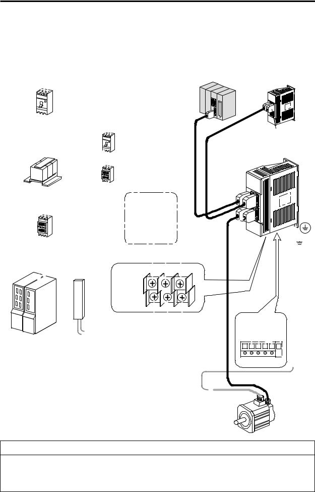
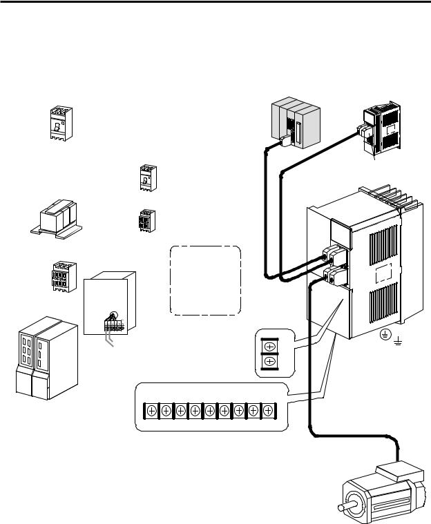
1.5.1 Basic configuration
<MDS-B-SPJ2-02 ~ MDS-B-SPJ2-075>
3-phase AC power supply
200V to 230V 50/60Hz
L1,L2,L3 |
Mitsubishi CNC |
|
No-fuse breaker |
|
|
|
SH21 cable |
|
(Note 1) |
SH21 cable to the |
Terminator |
next amplifier |
MDS -A - TM |
|
No-fuse breaker |
MDS-B-SPJ2-02 075 |
|
AC reactor |
||
|
|
|
Electromagnetic switch |
|
|
|
|
|
|
|
Turn OFF the main circuit |
|
|
|
|
|
|
|
power when an alarm occurs. |
|
|
|
|
|
Main circuit power |
|
|
|
|
|
|
|
|
|
|
|
|
|
|
|
Electromagnetic switch |
External electro- |
|
|
|
||
|
magnetic switch |
|
|
|
|||
|
|
|
control output |
|
|
|
|
|
|
|
|
|
|
|
|
|
|
|
D/A output (2ch) |
|
|
|
|
|
|
|
|
|
|
|
Grounding |
Control power |
|
|
|
|
|
|
|
|
|
|
Main circuit power L1 |
L2 |
L3 |
|
|
|
|
|
Main circuit |
|
|
|
|
|
|
|
output |
V |
W |
|
|
|
|
|
U |
|
|
||
|
|
|
|
|
|
|
|
|
|
|
Control power |
|
|
|
|
Spindle |
Power regeneration |
|
|
|
|
|
|
amplifier, etc. |
Regenerative resistor |
|
|
|
|
||
|
type convertor unit |
|
|
|
|
|
|
|
|
|
|
|
D |
C |
L21 N |
|
|
|
|
|
|
|
L11 |
|
|
|
|
|
Detector cable |
|
|
|
|
|
|
|
|
|
FCUAR052 R056 |
|
|
|
|
|
|
|
(SJ-P Series) |
|
|
|
|
|
AC spindle motor |
|
|
 CAUTION
(Note 1)
Install an independent no-fuse breaker for the MDS-B-SPJ2 main circuit power. This is especially necessary when the circuit is shared with a large capacity convertor unit, where the no-fuse breaker may not operate at a main circuit short-circuit in a small capacity spindle amplifier (SPJ2) if the no-fuse breaker is also installed so that it is shared. If this happens a fire may result.
1 − 4
1. Outline
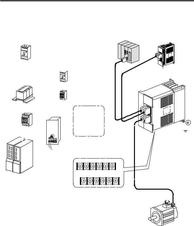
<MDS-B-SPJ2-15/22/37>
3-phase AC power supply
200V to 230V 50/60Hz
L1,L2,L3
No-fuse breaker
 (Note 1)
No-fuse breaker
Mitsubishi CNC
SH21 cable 
SH21 cable to the |
Terminator |
next amplifier |
MDS-A-TM |
MDS-B-SPJ2-15/22/37
|
AC reactor |
|
|
|
|
|
|
|
Electromagnetic switch |
|
|
||
|
|
Turn OFF the main circuit |
|
|||
|
|
power when an alarm occurs. |
|
|||
|
Main circuit power |
|
|
|
|
|
|
Electromagnetic |
|
|
|
|
|
|
switch |
External electro- |
|
|
||
|
|
magnetic switch |
|
|
||
|
|
control output |
|
|
||
Control |
|
|
|
|
||
power |
|
|
|
|||
D/A output (2ch) |
|
|
||||
|
|
|
|
|||
|
Regenerative |
|
|
|
|
|
|
resistor |
|
|
|
|
|
Spindle |
Power regeneration |
L11 L21 |
D |
P |
C N |
|
amplifier, etc. |
L1 |
L2 |
L3 |
U |
VW |
|
|
type convertor unit |
|
|
|
|
|
Grounding
Detector cable
FCUA-R052 R056 SJ-P Series
FCUA-R059 SJ-PF Series
AC spindle motor
1 − 5

1. Outline
<MDS-B-SPJ2-55/75>
3-phase AC power supply
200V to 230V 50/60Hz
L1,L2,L3
No-fuse breaker
AC reactor
Main circuit power
Control power
Regenerative resistor
Spindle
amplifier, etc. Power regeneration type convertor unit
Mitsubishi CNC
|
SH21 cable |
|
|
|
SH21 cable to the |
Terminator |
|
(Note 1) |
next amplifier |
||
MDS -A - TM |
|||
|
No-fuse breaker
MDS-B-SPJ2-55/75
Electromagnetic switch Turn OFF the main circuit
power when an alarm occurs.
External electromagnetic switch control output
D/A output (2ch)
Main circuit power
 L1
L1
 L2
L2
 L3
L3
C
P
N
U 
V
W
Grounding Control power

 L11
L11
 L21
L21
Detector cable
FCUA - R059 (SJ-PF Series)
AC spindle motor 
1 − 6
1. Outline
<MDS-B-SPJ2-110/110C>
3-phase AC power supply
200V to 230V 50/60Hz
L1,L2,L3
No-fuse breaker
AC reactor
Main circuit power
Control power
Mitsubishi CNC
SH21 cable
(Note 1)
No-fuse breaker
Electromagnetic switch Turn OFF the main circuit
power when an alarm occurs.
External electromagnetic switch control output
D/A output (2ch)
SH21 cable to |
Terminator |
|
the next amplifier |
||
MDS-A-TM |
MDS-B-SPJ2-110
Control power
|
Regenerative resistor |
L11 |
|
Grounding |
|
|
|
|
|
|
L21 |
Spindle |
L1 L2 L3 |
C P N U V W |
amplifier, etc. Power regeneration type |
|
|
|
convertor unit |
Detector cable |
|
|
|
|
|
FCUA-R059(SJ-PF Series |
|
Main circuit power |
|
|
|
AC spindle motor |
1 − 7
1. Outline
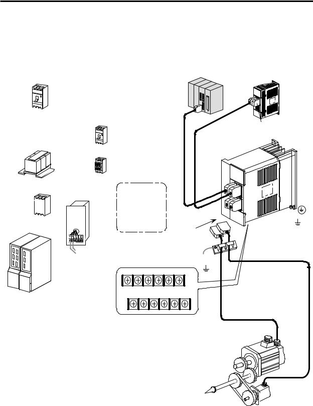
1.5.2 Encoder orientation (full closed)
<MDS-B-SPJ2-15/22/37>
3-phase AC power supply
200V to 230V 50/60Hz
L1,L2,L3
No-fuse breaker
AC reactor
Main circuit power
Electromagnetic switch
Control  power
power
Regenerative resistor
Spindle
amplifier, etc.Power regeneration type convertor unit
Mitsubishi CNC
SH21 cable
|
SH21 cable to the |
Terminator |
(Note 1) |
next amplifier |
MDS-A-TM |
No-fuse breaker |
MDS-B-SPJ2-15/22/37 |
|
Electromagnetic switch Turn OFF the main circuit
power when an alarm occurs.
External electromagnetic switch control output
D/A output (2ch) |
FCUA - R00 1 |
Grounding |
|
(Note 2) |
|
Control power |
|
|
L11 L21 D |
P |
C |
N |
Detector cable |
L1 L2 |
L3 |
U |
V W |
|
|
|
|
|
FCUA-R052 R056 (SJ-P Series) |
|
|
|
|
FCUA-R059 (SJ-PF Series) |
Main circuit power
AC spindle motor
 FCUAR050 R054
 Encoder
(Note 2)
When orientation, etc., is carried out using an external encoder, a motor detector cable and encoder cable are connected using a forked cable from the connector (CN2).
Note that when the cable shield is not connected to the ground via the connector case, the shield should be securely connected to the ground using a cable clamp jig, etc., as shown in the drawing. If the shield is not connected to the ground, it may cause the motor to produce abnormal noises or the orientation position to deviate.
1 − 8
Chapter 2 Specifications
Contents
2. Specifications ................................................................................................................ |
2 - 1 |
||
2.1 |
AC spindle motor and drive unit specifications ...................................................... |
2 - 1 |
|
2.2 |
Output characteristics ............................................................................................. |
2 - 3 |
|
2.3 |
Tolerable acceleration/deceleration frequency characteristics .............................. |
2 - 4 |
|
2.3.1 Frequency according to acceleration/deceleration time (tolerable duty cycle) |
2 - 4 |
||
2.3.2 Frequency according to regenerative resistor (tolerable duty cycle) ............. |
2 - 4 |
||
2.3.3 Combination of regenerative resistor capacity and unit ................................. |
2 - 5 |
||
2.4 |
Outline dimension ................................................................................................... |
2 - 6 |
|
2.4.1 |
Spindle drive unit ............................................................................................ |
2 - 6 |
|
2.4.2 |
Spindle motor .................................................................................................. |
2 - 10 |
|
2.4.3 |
Regenerative resistor ...................................................................................... |
2 - 17 |
|

2. Specifications
2. Specifications
2.1AC spindle motor and drive unit specifications
|
Motor series |
|
|
|
|
SJ-P Series |
|
|
|
|
||||
Specifications |
|
Spindle motor model |
SJ-P0.2A |
SJ-P0.4A |
|
SJ-P0.75A |
|
SJ-P1.5A |
|
SJ-P2.2A |
|
SJ-P3.7A |
||
|
Spindle drive unit |
MDS-B- |
MDS-B- |
|
MDS-B-SPJ |
MDS-B-SPJ |
|
MDS-B-SPJ |
|
MDS-B-SPJ |
||||
|
|
|
model |
|
SPJ2-02 |
SPJ2-04 |
|
2-075 |
|
2-15 |
|
2-22 |
|
2-37 |
|
Continuous |
|
Rated output |
(kW) |
0.1 |
0.15 |
|
0.3 |
|
0.55 |
|
1.1 |
|
1.5 |
|
characteristics |
|
Rated torque |
(Nm) |
0.64 |
0.96 |
|
1.91 |
|
3.5 |
|
7.0 |
|
9.55 |
|
(Note 1) |
|
|
|
|
|
|
|
|
|
|
|
|
|
|
|
|
(kgcm) |
6.5 |
9.8 |
|
19.5 |
|
35.7 |
|
71.4 |
|
97.4 |
|
|
|
|
|
|
|
|
|
|||||||
|
Short-time |
|
Rated output |
(kW) |
0.2 |
0.4 |
|
0.75 |
|
1.5 |
|
2.2 |
|
3.7 |
|
characteristics |
|
Rated torque |
(Nm) |
1.27 |
2.55 |
|
4.77 |
|
9.55 |
|
14.0 |
|
23.5 |
|
(10min) |
|
|
|
|
|
|
|
|
|
|
|
|
|
|
|
|
(kgcm) |
13 |
26 |
|
48.7 |
|
97.4 |
|
143 |
|
240 |
|
|
(Note 1) |
|
|
|
|
|
|
|||||||
|
Rated speed |
|
(r/min) |
|
|
1500 |
|
|
|
|
|
|||
|
Max. speed |
|
(r/min) |
|
10000 |
|
|
|
8000 |
|||||
motor |
Frame No. |
|
|
A46F |
B46F |
|
A71F |
|
B71F |
|
A112F |
|
B112F |
|
Max. torque |
|
(Nm) |
1.54 |
3.07 |
|
5.73 |
|
11.4 |
|
16.8 |
|
28.2 |
||
Spindle |
|
|
|
|
|
|
|
|
|
|
|
|
|
|
|
|
|
(kgcm) |
15.6 |
31.4 |
|
58.5 |
|
117 |
|
171 |
|
288 |
|
Max. current |
|
(A) |
2.5 |
5.0 |
|
6.5 |
|
11 |
|
14 |
|
23 |
||
|
Power rate |
|
(kW/sec) |
2.8 |
3.0 |
|
4.0 |
|
5.8 |
|
7.5 |
|
9.1 |
|
|
Moment of |
|
J |
(kgcm2) |
1.5 |
3.0 |
|
9.0 |
|
21 |
|
65 |
|
100 |
|
inertia |
|
GD2 |
(kgcm2) |
6.0 |
12 |
|
36 |
|
84 |
|
260 |
|
400 |
|
Speed position encoder |
|
|
Incremental encoder resolution 4096p/rev |
|
|||||||||
|
Accessories |
|
|
|
Thermal protector and oil seal provided |
|
||||||||
|
Structure |
|
|
|
Fully enclosed self-cooling (IP54) Flange installation |
|
||||||||
|
Ambient temperature |
|
|
|
|
0°C to 40°C |
|
|
|
|
||||
|
Weight |
|
(kg) |
4.5 |
6.5 |
|
10 |
|
20 |
|
25 |
|
35 |
|
|
|
|
Voltage, frequency |
|
3-phase 200V to 230VAC 50/60Hz |
|
||||||||
|
Power supply |
|
Tolerable voltage |
|
|
|
170V to 253V |
50/60Hz |
|
|
|
|
||
|
|
fluctuation |
|
|
|
|
|
|
|
|
||||
|
|
|
|
|
|
|
|
|
|
|
|
|
|
|
|
(Note 2) |
|
Tolerable frequency |
|
|
|
Within ± 5% |
|
|
|
|
|||
|
|
fluctuation |
|
|
|
|
|
|
|
|
||||
|
|
|
|
|
|
|
|
|
|
|
|
|
|
|
|
|
|
Power facility capacity |
0.5 |
1.0 |
|
2.0 |
|
3.0 |
|
4.0 |
|
7.0 |
|
|
Control method |
|
|
Sinusoidal PWM control, current control type vector control method |
||||||||||
|
Braking method |
|
|
|
Regenerative control (resistance electrical-discharge) |
|
||||||||
unit |
Speed control range |
|
|
|
|
35 to 10000 (r/min) |
|
|
|
|
||||
Tolerable load moment of inertia |
|
10-times or less of motor moment of inertia |
|
|||||||||||
drive |
|
|
||||||||||||
Controller connection specifications |
|
HDLC high-speed serial bus connection |
|
|||||||||||
Spindle |
|
|
|
|
Overcurrent shut off, overvoltage shut off, overload shut off (thermal relay), |
|||||||||
Protective functions |
|
undervoltage protection, main circuit element overheat protection, |
|
|||||||||||
|
regenerative resistor overheat protection, overspeed protection, |
|
||||||||||||
|
|
|
|
|
excessive error protection, detector error protection |
|
|
|
|
|||||
|
|
|
Ambient temperature |
|
0°C to 55°C (with no freezing) |
Storage –20°C to 65°C |
|
|||||||
|
|
|
Ambient humidity |
|
90%RH (with no dew condensation) |
|
||||||||
|
Environment |
|
Atmosphere |
|
|
|
|
No corrosive gases or dust |
|
|
|
|
||
|
|
|
Altitude |
|
|
|
|
1000m or less |
|
|
|
|
||
|
|
|
Vibration |
|
|
|
|
5.9m/S2 (0.6G) or less |
|
|
|
|
||
|
Outline dimensions H×W×D |
(mm) |
168×54×135 |
168 × 70 × 135 |
|
|
168 × 90 × 195 |
|
||||||
|
Weight |
|
(kg) |
0.8 |
|
1.0 |
|
|
2.3 |
|
|
|||
Note 1) The rated output is guaranteed at the rated input voltage (200 to 230VAC). If the input voltage fluctuates and drops below this value, the rated output may not be achieved.
Note 2) When using a voltage not within the above specifications, prepare a power supply transformer.
2 − 1

2. Specifications
Motor series |
|
|
|
|
SJ-PF Series |
|
|
|
|
Spindle motor model |
SJ-PF2.2-01 |
SJ-PF3.7-01 |
SJ-PF5.5-01 |
SJ-PF7.5-01 |
SJ-PF11-01 |
||
|
|
In-panel |
MDS-B-SPJ2- |
MDS-B-SPJ2-3 |
MDS-B-SPJ2-5 |
MDS-B-SPJ2-7 |
MDS-B-SPJ2-1 |
|
|
|
installation |
||||||
|
Spindle |
22 |
7 |
5 |
5 |
10 |
||
Specifications |
type |
|
||||||
drive |
Intermediate |
|
|
|
|
|
||
|
unit |
|
|
|
|
|
||
|
panel |
|
|
|
|
|
MDS-B-SPJ2-1 |
|
|
model |
|
|
|
|
|
||
|
installation |
|
|
|
|
10C |
||
|
|
|
|
|
|
|||
|
|
type |
|
|
|
|
|
|
Continuous |
Rated output |
(kW) |
1.5 |
2.2 |
3.7 |
5.5 |
7.5 |
|
characteristics |
Rated torque |
(Nm) |
9.55 |
14.0 |
23.5 |
35.0 |
47.8 |
|
|
(Note 1) |
|
(kgcm) |
97.5 |
143 |
240 |
|
357 |
487 |
|
Short-time |
Rated output |
(kW) |
2.2 (15 min.) |
3.7 (15 min.) |
5.5 (30 min.) |
7.5 (30 min.) |
11.0 (30 min.) |
|
|
characteristics |
Rated torque |
(Nm) |
14.0 |
23.5 |
35.0 |
|
47.8 |
70.0 |
|
(10min) |
|
(kgcm) |
143 |
240 |
357 |
|
487 |
715 |
|
(Note 1) |
|
|
||||||
|
Rated speed |
|
(r/min) |
|
|
1500 |
|
|
|
motor |
Max. speed |
|
(r/min) |
10000 |
|
8000 |
6000 |
||
Frame No. |
|
|
A90 |
B90 |
D90 |
|
A112 |
B112 |
|
|
|
|
|
||||||
Spindle |
Max. torque |
|
(Nm) |
16.8 |
28.2 |
42.0 |
|
57.4 |
84.1 |
Max. current |
|
(A) |
17 |
28 |
37 |
|
53 |
64 |
|
|
|
|
(kgcm) |
171 |
283 |
428 |
|
584 |
858 |
|
Power rate |
|
(kW/sec) |
14 |
23 |
40 |
|
52 |
76 |
|
Moment of |
J |
(kgcm2) |
65 |
85 |
137 |
|
235 |
298 |
|
inertia |
GD2 |
(kgcm2) |
260 |
340 |
550 |
|
940 |
1190 |
|
Speed position encoder |
|
|
Incremental encoder resolution 4096p/rev |
|
||||
|
Accessories |
|
|
|
Thermal protector provided |
|
|||
|
Structure |
|
|
|
Fully enclosed self-cooling (IP54) flange installation |
|
|||
|
Ambient temperature |
|
|
|
0°C to 40°C |
|
|
||
|
Weight |
|
(kg) |
25 |
30 |
49 |
|
60 |
70 |
|
|
Voltage, frequency |
|
3-phase 200V to 230VAC |
50/60Hz |
|
|||
|
Power supply |
Tolerable voltage |
|
|
170V to 253V |
50/60Hz |
|
||
|
fluctuation |
|
|
|
|
||||
|
|
|
|
|
|
|
|
|
|
|
(Note 2) |
Tolerable frequency |
|
|
Within ± 5% |
|
|
||
|
fluctuation |
|
|
|
|
|
|||
|
|
Power facility capacity |
4.0 |
7.0 |
9.0 |
|
12.0 |
17.0 |
|
|
Control method |
|
|
Sinusoidal PWM control, current control type vector control method |
|||||
|
Braking method |
|
|
|
Regenerative control (resistance electrical-discharge) |
|
|||
|
Speed control range |
|
|
|
35 to 8000 (r/min) |
|
|
||
|
Tolerable load moment of inertia |
|
10-times or less of motor moment of inertia |
|
|||||
|
Controller connection specifications |
|
HDLC high-speed serial bus connection |
|
|||||
unit |
|
|
|
Overcurrent shut off, overvoltage shut off, overload shut off (thermal relay), |
|||||
|
|
|
undervoltage protection, main circuit element overheat protection, |
|
|||||
drive |
Protective functions |
|
|
||||||
|
regenerative resistor overheat protection, overspeed protection, |
|
|||||||
|
|
|
|||||||
|
|
|
|
|
|||||
Spindle |
|
|
|
excessive error protection, detector error protection |
|
|
|||
|
Ambient temperature |
|
0°C to 55°C (with no freezing) |
Storage –20°C to 65°C |
|
||||
|
|
|
|
||||||
|
|
Ambient humidity |
|
90%RH (with no dew condensation) |
|
||||
|
Environment |
Atmosphere |
|
|
No corrosive gases or dust |
|
|||
|
|
Altitude |
|
|
|
1000m or less |
|
|
|
|
|
Vibration |
|
|
|
5.9m/S2 (0.6G) or less |
|
||
|
Outline |
In-panel installation |
168 × 90 × 195 |
250 × 130 × 200 |
380×180×200 |
||||
|
dimensions |
type |
|
||||||
|
|
|
|
|
|
|
|
||
|
H×W×D |
Intermediate panel |
|
|
|
|
|
350×180×200 |
|
|
(mm) |
installation type |
|
|
|
|
|
||
|
|
|
|
|
|
|
|||
|
Weight |
|
(kg) |
|
2.3 |
|
4.5 |
6.5 |
|
Note 1) The rated output is guaranteed at the rated input voltage (200 to 230VAC). If the input voltage fluctuates and drops below this value, the rated output may not be achieved.
Note 2) When using a voltage not within the above specifications, prepare a power supply transformer.
2 − 2
2. Specifications
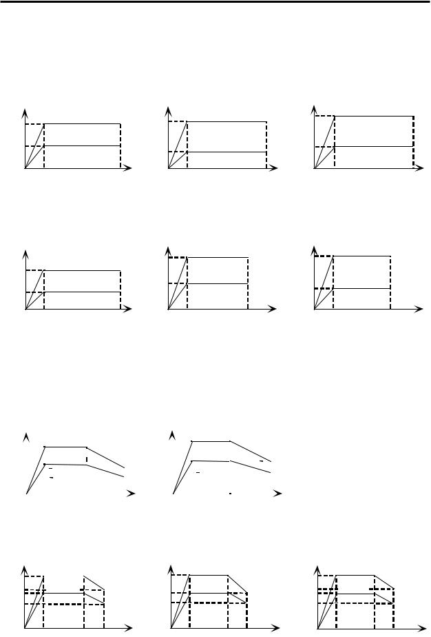
2.2Output characteristics
● |
SJ-P Series |
|
|
|
|
|
|
|
|
|
SJ-P0.2A |
|
|
SJ-P0.4A |
(kW) |
|
SJ-P0.75A |
(kW) |
(kW) |
|
|
|||||
|
|
|
|
|||||
|
|
Output |
|
|
||||
Output |
|
|
Output |
|
|
|
|
|
|
|
|
|
|
|
Short-time rating |
||
|
Short-time rating |
|
|
Short-time rating |
0.75 |
|
||
|
|
0.4 |
|
|
||||
0.2 |
|
|
|
|
||||
|
|
|
|
|
|
|
|
|
0.1 |
|
Continuous rating |
|
|
Continuous rating |
|
|
Continuous rating |
|
|
0.15 |
|
0.3 |
|
|
||
|
|
|
|
|
|
|
||
0 |
|
|
|
|
|
0 |
|
|
|
|
|
0 |
|
|
|
|
|
|
1500 |
10000 |
1500 |
10000 |
|
|
10000 |
|
|
|
|
1500 |
|||||
|
|
|
|
|
|
|
|
|
|
|
Speed (r/min) |
|
Speed (r/min) |
|
Speed (r/min) |
||
|
|
|
|
|
|
|||
(kW) |
|
SJ-P1.5A |
(kW) |
|
SJ-P2.2A |
|
(kW) |
SJ-P3.7A |
|
|
|
|
|
|
|||||
Output |
|
|
Output |
|
Short-time rating |
Output |
Short-time rating |
||
|
|
|
|
3.7 |
|
||||
|
|
|
2.2 |
|
|
||||
1.5 |
|
Short-time rating |
|
|
|
|
|
|
|
|
|
Continuous rating |
1.1 |
|
Continuous rating |
1.5 |
|
Continuous rating |
|
0.55 |
|
|
|
|
|
||||
|
|
|
|
|
|
|
|
|
|
0 |
1500 |
10000 |
0 |
1500 |
8000 |
0 |
|
1500 |
8000 |
|
|
|
|
||||||
|
|
Speed (r/min) |
|
Speed (r/min) |
|
|
Speed (r/min) |
|
|
|
|
|
|
|
|
|
|
|
|
●SJ-PF Series
|
|
|
|
|
|
|
|
|
|
|
|
|
SJ-PF2.2-01 |
(kW) |
|
|
|
SJ-PF3.7-01 |
|||||||||||||||||||||||||||||||||||||||||||||||||||||||||||||||
|
(kW) |
|
|
|
|
|
|
|
|
|
|
|
|
|
|
|
|
|
|
|
|
|
|
|
|
|
|
|
|
|
|
|
|
|
|
|
|
|
|||||||||||||||||||||||||||||||||||||||||||
|
|
|
|
|
|
|
|
|
|
|
|
|
|
|
|
|
|
|
|
|
|
|
|
|
|
|
|
|
|
|
|
|
|
|
|
|
|
|
|
|
|
|
|
|
|
|
|
|
|
|
|
|
|
|
|
|
|
|
|
|
|||||||||||||||||||||
|
|
|
|
|
|
|
|
|
|
|
|
|
|
|
|
|
|
|
|
|
|
|
|
|
|
Output |
|
|
|
|
|
|
|
|
|
|
|
|
|
|
|
|
|
|
|
|
|
|
|
|
|
|
|
|
|
|
|
|
|
|
|
||||||||||||||||||||
Output |
|
|
|
|
|
|
|
|
|
|
|
|
|
|
|
|
|
|
|
|
|
|
|
|
|
|
|
|
|
|
|
|
|
|
|
|
|
|
|
|
|
|
|
|
|
|
|
|
|
|
|
|
|
|
|
|
|
|
|
|
|||||||||||||||||||||
|
|
|
|
|
|
|
|
|
|
|
|
|
|
|
|
|
|
|
|
|
|
|
|
|
|
|
|
|
|
|
|
15 minute rating |
|
|
|
|
|
|
|
|
|
|
|
|
|
|
|
|
|
||||||||||||||||||||||||||||||||
2.2 |
|
|
|
|
|
|
|
|
15 minute rating |
|
|
|
|
|
|
|
|
|
|
3.7 |
|
|
|
|
|
|
|
|
|
|
|
|
|
|
|
|
|
|
|
|
|
|
|
|
|
|
|
|
|
|
|
|
|
|
|
|
|
|
|
|
|
|
|
|
|
||||||||||||||||
|
|
|
|
|
|
|
|
|
|
|
|
|
|
|
|
|
|
|
|
|
|
|
|
|
|
|
|
|
|
|
|
|
|
|
|
|
|
|
|
|
|
|
|
|
|
|
|
|
|
|
|
|
|
|
|
|
|
|
|
|
|
|
|||||||||||||||||||
|
|
|
|
|
|
|
|
|
|
|
|
|
|
|
|
|
|
|
|
|
|
|
|
|
|
|
|
|
|
|
|
|
|
|
|
|
|
|
|
|
|
|
|
|
|
|
|
|
|
|
|
|
|
|
|
|
|
|
|
|
|
|
|
|
|
|
|
|
|
|
|
|
|
|
|
|
|
|
|
|
|
|
|
|
|
|
|
|
|
|
|
|
|
|
|
|
|
|
|
|
|
|
|
|
|
|
|
|
|
|
|
|
|
|
|
|
|
|
|
|
|
|
|
|
|
Continuous |
rating |
|
|
|
|
|
|
|
|
|
|
|
|
|
|
|
|
|
|||||||||||||||||||
11..35 |
|
|
|
|
|
|
|
|
Continuous rating |
|
|
|
|
|
|
|
|
|
|
2.2 |
|
|
|
|
|
|
|
|
|
|
|
|
|
|
|
|
|
|
|
|
|
|
|
|
|||||||||||||||||||||||||||||||||||||
|
|
|
|
|
|
|
|
|
|
|
|
|
|
|
|
|
|
|
|
|
|
|
|
|
|
|
|
|
|
|
|
|
|
|
|
|
|
|
|
|
|
|
|
|
|
|
|
|
|
|
|
|
|
|
|
|
|
|
|
|
|
|
|
|
|
|
|
|
|
|
|
|
|
|
|
|
|
|
|
||
|
|
|
|
|
|
|
|
|
|
|
|
|
|
|
|
|
|
|
|
|
|
|
|
|
|
|
|
|
|
|
|
|
|
|
1.5 |
|
|
|
|
|
|
|
|
|
|
|
|
|
|
|
|
|
|
|
|
|
|
|
|
|
|
|
|
|
|
|
|
|
|
|
|
|
|
|
|
|
|
|
|
|
|
0.9 |
|
|
|
|
|
|
|
|
|
|
|
|
|
|
|
|
|
|
|
|
|
|
|
|
|
|
|
|
|
|
|
|
|
|
|
|
|
|
|
|
|
|
|
|
|
|
|
|
|
|
|
|
|
|
|
|
|
|
|
|
|
|
|
|
|
|
|
|
|
|
|
|
|
|
|
|
|
|
|
|
|
0 |
|
|
|
|
|
|
|
|
|
|
|
|
|
|
|
|
|
|
|
|
|
|
|
|
|
|
|
|
|
|
|
|
|
|
|
0 |
|
|
|
|
|
|
|
|
|
|
|
|
|
|
|
|
|
|
|
|
|
|
|
|
|
|
|
|
|
|
|
|
|
|
|
|
|
|
|
|
|
|
|
|
|
|
|
|
|
|
|
|
|
|
|
|
|
|
|
|
|
|
|
|
|
|
|
|
|
|
|
|
|
|
|
|
|
|
|
|
|
|
|
|
|
|
|
|
|
|
|
|
|
|
|
|
|
|
|
|
|
|
|
|
|
|
|
|
|
|
|
|
|
|
|
|
|
|
|
|
|
|
|
|
|
||
1500 |
6000 |
|
|
10000 |
1500 |
6000 |
|
|
10000 |
||||||||||||||||||||||||||||||||||||||||||||||||||||||||||||||||||||||||
|
|
|
|
|
|||||||||||||||||||||||||||||||||||||||||||||||||||||||||||||||||||||||||||||
|
|
|
|
|
|
|
|
|
|
|
|
|
|
|
|
|
|
|
|
|
|
|
|
|
|
|
|
|
|
|
|
|
|
|
|
|
|
|
|
|
|
|
|
|
|
|
|
|
|
|
|
|
|
|
|
|
|
|
|
|
|
|
|
|
|
|
|
|
|
|
|||||||||||
Speed (r/min) |
Speed (r/min) |
|
(kW) |
|
SJ-PF5.5-01 |
(kW) |
SJ-PF7.5-01 |
(kW) |
|
SJ-PF11-01 |
|||
|
|
|
|
|
||||||
Output |
30 minute rating |
Output |
30 minute rating |
|
Output |
30 minute rating |
|
|||
7.5 |
|
|
||||||||
5.5 |
|
11 |
|
|
|
|||||
4.0 |
Continuous |
|
Continuous |
|
Continuous |
|
||||
|
|
8.3 |
|
|||||||
3.7 |
rating |
5.5 |
rating |
|
|
7.55.6 |
rating |
|
||
2.5 |
|
|
4.0 |
|
|
|
|
|
|
|
|
|
|
|
|
|
|
|
|
|
|
0 |
1500 |
6000 8000 |
0 |
1500 |
6000 |
8000 |
0 |
|
4500 |
6000 |
|
|
|
1500 |
|||||||
|
Speed (r/min) |
|
Speed (r/min) |
|
|
Speed (r/min) |
|
|||
|
|
|
|
|
|
|
|
|
||
2 − 3
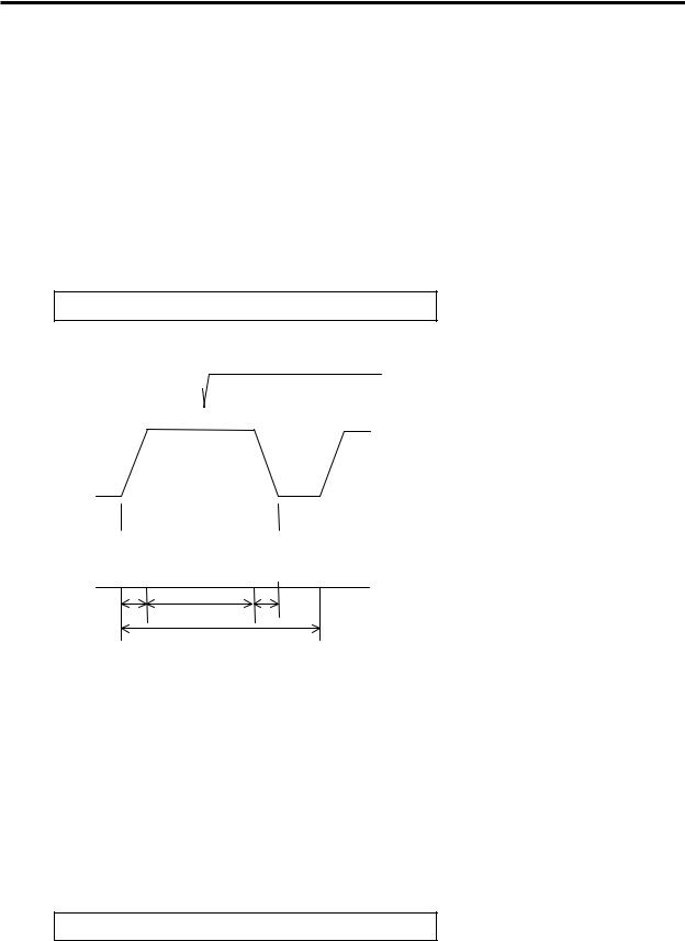
2.Specifications
2.3Tolerable acceleration/deceleration frequency characteristics
The tolerable acceleration/deceleration frequency characteristics of the controller fluctuate according to the motor speed and motor shaft conversion GD2, so calculate the tolerable frequency with the following items. The smaller of the frequency determined by the acceleration/deceleration time according to the controller output (refer to appendix) and the frequency determined by the regenerative resistor becomes the operable frequency (tolerable duty cycle).
2.3.1Frequency according to acceleration/deceleration time (tolerable duty cycle)
When machining with a frequent spindle acceleration/deceleration, the average output value per cycle must not exceed the continuous rated output.
Continuous rated output ≥ 1 cycle average output value
(1) How to obtain the average output
Average output |
PAV = |
|
P12 |
• t1 + P22 |
• t2 + P32 • t3 |
||||||
|
|
|
|
T |
|||||||
|
|
|
|
|
|
|
|
||||
Motor speed |
|
|
|
|
|
|
|
|
|
||
|
Accel- |
|
|
|
Decel- |
|
|
|
|||
|
eration |
|
|
|
eration |
|
|
|
|||
|
P1 |
|
|
|
|
|
P3 |
|
|
P1 |
|
Motor output |
|
|
Cutting |
|
|
|
|
|
|
||
|
|
|
P2 |
|
|
|
|
|
|
||
|
|
|
|
|
|
|
|
|
|
||
P1, P3 : Output (kW) during acceleration/ deceleration
P2 |
30 minute rated output × 1.2 |
: Output (kW) during cutting |
|
t1, t3 |
: Acceleration/deceleration time |
t1 |
t2 |
t3 |
|
1 cycle T |
|
2.3.2Frequency according to regenerative resistor (tolerable duty cycle)
The energy during motor deceleration (during regeneration) is consumed by the regenerative resistor. This heating value of this regenerative resistor changes according to the motor type, speed being used, load inertia and continuous repetition cycle (duty cycle).
Use a regenerative resistor with an adequate capacity according to the load and continuous cycle time.
(1)How to obtain the regenerative resistor capacity
Obtain the rotation energy with the following equation, and select so that the value does not exceed the capacity of the regenerative resistor.
Regenerative resistor capacity ≥ Motor rotation energy
Refer to section 2.3.3 for the regenerative resistor capacity.
2 − 4

2. Specifications
The spindle motor rotation energy W is :
|
n |
|
( GDM2 + GDL2 ) |
|
2 |
π • |
|
W = |
|
× |
4 |
× [ |
N |
] 2 |
|
120 |
|
60 |
|||||
|
GDM2 |
||
|
GDL2 |
||
|
N |
||
|
n |
||
n = |
60 |
|
|
T |
|||
|
|||
: |
Motor rotor inertia |
(kg•m2) |
: |
Motor shaft conversion load inertia |
(kg•m2) |
: |
Motor speed |
(r/min) |
: |
Acceleration/deceleration frequency |
(times/min.) |
|
T : Tolerable duty cycle |
(sec) |
2.3.3Combination of regenerative resistor capacity and unit
The combinations of the regenerative resistor capacity (tolerable heating value) and the unit are shown below.
|
Tolerable |
Resistance |
|
Combination with spindle drive unit |
|||||||
Model |
heating |
value |
|
|
|
(MDS-B-SPJ2-**) |
|||||
|
value |
(ohm) |
-02 |
-04 |
-075 |
-15 |
-22 |
-37 |
-55 |
-75 |
-110 |
|
|
|
|||||||||
No regenerative |
— |
— |
|
|
|
|
|
|
|
|
|
resistor |
|
|
|
|
|
|
|
|
|
||
|
|
|
|
|
|
|
|
|
|
|
|
FCUA-RB04 |
60W |
200 |
|
|
|
|
|
|
|
|
|
FCUA-RB075 |
80W |
100 |
|
|
|
|
|
|
|
|
|
FCUA-RB15 |
120W |
60 |
|
|
|
|
|
|
|
|
|
FCUA-RB22 |
155W |
40 |
|
|
|
|
|
|
|
|
|
FCUA-RB37 |
185W |
25 |
|
|
|
|
|
|
|
|
|
FCUA-RB75/2 |
340W |
30 |
|
|
|
|
|
|
|
|
|
1 unit used |
|
|
|
|
|
|
|
|
|
||
|
|
|
|
|
|
|
|
|
|
|
|
FCUA-RB55 |
340W |
20 |
|
|
|
|
|
|
|
|
|
FCUA-RB75/2 |
680W |
15 |
|
|
|
|
|
|
|
|
|
Two units in series |
|
|
|
|
|
|
|
|
|
||
|
|
|
|
|
|
|
|
|
|
|
|
R-UNIT1 |
700W |
15 |
|
|
|
|
|
|
|
|
|
R-UNIT2 |
700W |
15 |
|
|
|
|
|
|
|
|
|
R-UNIT3 |
2100W |
15 |
|
|
|
|
|
|
|
|
|
R-UNIT4 |
2100W |
10 |
|
|
|
|
|
|
|
|
|
R-UNIT5 |
3100W |
10 |
|
|
|
|
|
|
|
|
|
If repeated frequency operation exceeding the regenerative resistor capacity is carried out, and over-regeneration alarm will occur and the spindle drive unit will stop.
The over-regeneration alarm detects the cumulative value of the current that flows within a set time to the regenerative resistor. The alarm can be released just by turning the power ON again, but do not resume operation immediately.
If operation is resumed before the regenerative resistor cools, the regenerative resistor could burn out and fires could occur. Always resume operation after the regenerative resistor cools.
2 − 5

2. Specifications
2.4Outline dimension
2.4.1 Spindle drive unit
• MDS-B-SPJ2-02
[unit: mm]
Wiring space |
135 |
|
(75 or more) |
||
|
|
50 |
Heat radiation |
|
6 |
φ6 installation hole |
||
space |
|||
6 |
|
(40 or more) |
168 |
156 |
|
|
|
|
|
|
|
|
|
|
|
|
|
|
|
|
|
|
|
|
|
|
|
|
|
|
|
|
|
|
|
|
|
|
|
|
|
|
|
|
|
|
|
|
|
|
|
|
|
|
||
|
|
|
|
|
|
|
|
|
|
|
|
|
|
|
|
|
|
|
|
|
|
|
|
|
||
|
|
|
|
|
|
|
|
|
|
|
|
|
|
|
|
|
|
|
|
|
|
|
|
|
||
|
|
|
|
|
|
|
|
|
|
|
|
|
|
|
|
|
|
|
|
|
|
|
|
|
|
|
6 |
6 3-M4×0.7 |
Wiring space |
6 |
(40 or more) |
4 |
• MDS-B-SPJ2-04/075
6

168 |
156 |
6
70
φ6 installation hole
22
|
6 |
6 |
|
6 |
|
22 |
|
|
|
3-M4×0.7 |
|
|
|
Wiring space |
|
|
|
|
|
|
|
|
|
|
|
|
|
|
|
|
|
|
|
[unit: mm] |
|||||||||||||||
(75 or more) |
135 |
|
|
|
|
|
|
|
|
|
|
|
|
|
|
|
|
|
|
|
|
|
|
|
|
|
|
|
|||||||
|
|
|
|
|
|
|
|
|
|
|
|
|
|
|
|
|
|
|
|
|
|||||||||||||||
|
|
|
|
|
|
Heat radiation space |
|||||||||||||||||||||||||||||
|
|
|
|
|
|
(40 or more) |
|||||||||||||||||||||||||||||
|
|
|
|
|
|
|
|
|
|
|
|
|
|
|
|
|
|
|
|
|
|
|
|
|
|
|
|
|
|
|
|
|
|
|
|
|
|
|
|
|
|
|
|
|
|
|
|
|
|
|
|
|
|
|
|
|
|
|
|
|
|
|
|
|
|
|
|
|
|
|
|
|
|
|
|
|
|
|
|
|
|
|
|
|
|
|
|
|
|
|
|
|
|
|
|
|
|
|
|
|
|
|
|
|
|
|
|
|
|
|
|
|
|
|
|
|
|
|
|
|
|
|
|
|
|
|
|
|
|
|
|
|
|
|
|
|
|
|
|
|
|
|
|
|
|
|
|
|
|
|
|
|
|
|
|
|
|
|
|
|
|
|
|
|
|
|
|
|
|
|
|
|
|
|
|
|
|
|
|
|
|
|
|
|
|
|
|
|
|
|
|
|
|
|
|
|
|
|
|
|
|
|
|
|
|
|
|
|
|
|
|
|
|
|
|
|
|
|
|
|
|
|
|
|
|
|
|
|
|
|
|
|
|
|
|
|
|
|
|
|
|
|
|
|
|
|
|
|
|
|
|
|
|
|
|
|
|
|
|
|
|
|
|
|
|
|
|
|
|
|
|
|
|
|
|
|
|
|
|
|
|
|
|
|
|
|
|
|
|
|
|
|
|
|
|
|
|
|
|
|
|
|
|
|
|
|
|
|
|
|
|
|
|
|
|
|
|
|
|
|
|
|
|
|
|
|
|
|
|
|
|
|
|
|
|
|
|
|
|
|
|
|
|
|
|
|
|
|
|
|
|
|
|
|
|
|
|
|
|
|
|
|
|
|
|
|
|
|
|
|
|
|
|
|
|
|
|
|
|
|
|
|
|
|
|
|
|
|
|
|
|
|
|
|
|
|
|
|
|
|
|
|
|
|
|
|
|
|
|
|
|
|
|
|
|
|
|
|
|
|
|
|
|
|
|
|
|
|
|
|
|
|
|
|
|
|
|
|
|
|
|
|
|
|
|
|
|
|
|
|
|
|
|
|
|
|
|
|
|
|
|
|
|
|
|
|
|
|
|
|
|
|
|
|
|
|
|
|
|
|
|
|
|
|
|
|
|
|
|
|
|
|
|
|
|
|
|
|
|
|
|
|
|
|
|
|
|
|
|
|
|
|
|
|
|
|
|
|
|
|
|
|
|
|
|
|
|
|
|
|
|
|
|
|
|
|
|
|
|
|
|
|
|
|
|
|
|
|
|
|
|
|
|
|
|
|
|
|
|
|
|
|
|
|
|
|
|
|
|
|
|
|
|
|
|
Wiring space (40 or more)

 6
6
2 − 6
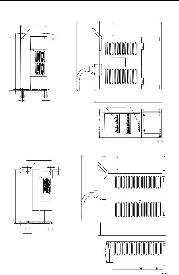
2. Specifications
• MDS-B-SPJ2-15/22/37 |
Wiring space |
|
[unit: mm] |
||
|
|
|
|
|
|
|
|
90 |
(75 or more) |
195 |
|
|
|
|
|
|
|
|
|
φ6 installation hole |
Heat radiation space (40 or more) |
||
|
6 |
6 |
6 |
||
|
6 |
|
|
|
|
168 |
156 |
|
|
|
|
|
6 |
|
|
|
|
|
6 |
6 |
|
Wiring space (40 or more) |
|
|
6 |
6 |
|
|
|
|
|
|
|
12-M4×0.7 screws |
3-M4×0.7 screws |
• MDS-B-SPJ2-55/75
130 |
2-φ6 installation |
|
7.5 |
6 |
6 |
hole |
|
7.5 |
|||
|
|
|
||
250 |
235 |
|
|
|
|
7.5 |
|
|
|
|
|
6 |
6 |
|
|
|
|
||
|
|
6 |
|
|
|
|
|
|
|
|
|
|
|
|
|
|
|
|
|
|
|
|
|
|
|
|
|
|
|
|
|
|
|
|
|
|
|
|
|
|
|
|
|
|
|
|
|
|
|
Wiring space |
|
|
|
|
|
|
|
|
|
|
|
|
|
|
|
|
|
|
|
|
|
|
|
|
|
|
|
|
|
|
|
|
|
|
|
|
|
|
|
|
6 |
|
|
|
|
|
|
|
|
|
|
|
|
|
|
|
|
|
|
|
|
|
|
|
|
|
|
|
|
|
|
|
|
|
|
|
|
|
|
|
|
|
|
|
|
||||
|
|
|
|
|
|
|
|
|
|
|
|
|
|
|
|
|
|
|
|
|
|
|
|
|
|
|
|
|
|
|
|
|
|
|
|
|
|
|
|
|
|
|||
|
|
|
|
|
|
|
|
|
|
|
|
|
|
|
|
|
|
|
|
|
|
|
|
|
|
|
|
|
|
|
|
|
|
|
|
|
|
|
|
|
|
|||
|
|
|
|
|
|
|
|
|
|
|
|
|
|
|
|
|
|
|
|
|
|
|
|
|
|
|
|
|
|
|
|
|
|
|
[unit: mm] |
|||||||||
(70 or more) |
|
200 |
|
|
|
|
|
|
|
|
|
|
|
|
|
|
|
|
|
|
|
|
||||||||||||||||||||||
|
|
|
|
|
|
|
|
|
Heat radiation space (40 or more) |
|||||||||||||||||||||||||||||||||||
|
|
|
|
|
|
|
|
|
|
|
|
|
|
|
|
|
|
|
|
|
|
|
|
|
|
|
|
|
|
|
|
|
|
|
|
|
|
|
|
|
|
|
|
|
|
|
|
|
|
|
|
|
|
|
|
|
|
|
|
|
|
|
|
|
|
|
|
|
|
|
|
|
|
|
|
|
|
|
|
|
|
|
|
|
|
|
|
|
|
|
|
|
|
|
|
|
|
|
|
|
|
|
|
|
|
|
|
|
|
|
|
|
|
|
|
|
|
|
|
|
|
|
|
|
|
|
|
|
|
|
|
|
|
|
|
|
|
|
|
|
|
|
|
|
|
|
|
|
|
|
|
|
|
|
|
|
|
|
|
|
|
|
|
|
|
|
|
|
|
|
|
|
|
|
|
|
|
|
|
|
|
|
|
|
|
|
|
|
|
|
|
|
|
|
|
|
|
|
|
|
|
|
|
|
|
|
|
|
|
|
|
|
|
|
|
|
|
|
|
|
|
|
|
|
|
|
|
|
|
|
|
|
|
|
|
|
|
|
|
|
|
|
|
|
|
|
|
|
|
|
|
|
|
|
|
|
|
|
|
|
|
|
|
|
|
|
|
|
|
Wiring space (40 or more)
 6
6
2 − 7
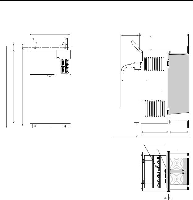
2. Specifications
• MDS-B-SPJ2-110 |
|
|
|
|
|
180 |
|
15 |
7.5 |
150 |
6 |
130 |
|||
380 |
350 |
365 |
|
|
|
|
|
|
|
|
|
|
|
|
|
|
|
|
|
|
|
|
|
|
|
|
|
|
|
|
|
|
|
|
|
|
|
|
|
|
|
|
|
|
|
|
|
|
|
|
|
|
|
|
|
|
Wiring space |
[unit: mm] |
|
(70 or more) |
200 |
|
|
|
|
Heat radiation space (40 or more)
Wiring space |
|
|
|
|
|
|
|
|
|
|
|
|
|
|
|
|
|
|
|
|
|
|
|
|
|
|
|
|
|
|
|
|
|
|
|
|
|
|
|
|
|
|
|
|
|
|
|
|
|
|
|
|
|
|
|
|
|
|
|
|
|
|
|
|
|
|
|
|
|
|
|
|
|
|
|
|
|
|
|
|
|
|
|
|
|
|
|
|
|
|
|
|
|
|
|
|
|
|
|
|
|
|
|
|
|
|
|
|
|
|
|
|
|
|
|
|
|
|
|
|
|
|
|
|
|
|
|
|
|
|
|
|
|
|
|
|
|
|
|
|
|
|
|
|
|
|
|
|
|
|
|
|
|
|
|
|
|
|
|
|
|
|
|
|
|
|
|
|
|
|
|
|
|
|
|
|
|
|
|
|
|
|
|
|
|
|
|
|
|
|
|
|
|
|
|
|
|
|
|
|
|
|
|
|
|
|
|
|
|
|
|
|
|
|
|
|
138 |
|
|
|
|
|
|
|
|
|
|
62 |
|||||||||||||||||||
(40 or more)
9-M4×0.7 screws
3-M4×0.7 screws
6 |
2 − 8
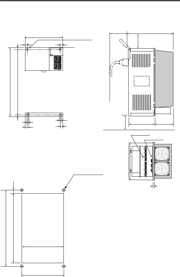
2. Specifications
• MDS-B-SPJ2-110C |
|
|
|
|
||
|
|
|
|
Wiring space |
|
[unit: mm] |
|
|
|
|
|
|
|
|
|
|
2-φ6 installation |
(70 or more) |
200 |
|
|
|
180 |
|
|
|
|
|
7.5 |
6 |
hole |
|
Heat radiation space |
|
|
6 |
|
||||
|
|
(40 or more) |
|
|||
|
|
|
|
|||
|
|
|
|
|
|
|
350 |
335 |
|
|
|
|
|
|
7.5 |
6 |
6 |
Wiring space |
138 |
62 |
|
6 |
|||||
|
|
|
||||
|
|
6 |
|
(40 or more) |
|
|
|
|
|
|
|
|
|
|
|
|
|
|
9-M4×0.7 screws |
|
|
|
|
|
|
3-M4×0.7 screws |
|
< Embedded installation |
Installation hole dimensions > |
|
|
|
||
|
|
|
4-M5 screws |
|
|
|
|
|
|
|
|
6 |
|
8
335 |
319 |
|
|
166
168
2 − 9
Loading...