


 Loading...
MELDAS is a registered trademark of Mitsubishi Electric Corporation.
Other company and product names that appear in this manual are trademarks or registered trademarks of their respective companies.
Introduction
Thank you for selecting the Mitsubishi numerical control unit.
This instruction manual describes the handling and caution points for using this AC servo/spindle.
Incorrect handling may lead to unforeseen accidents, so always read this instruction manual thoroughly to ensure correct usage.
Make sure that this instruction manual is delivered to the end user.
Always store this manual in a safe place.
In order to confirm if all function specifications described in this manual are applicable, refer to the specifications for each CNC.
Notes on Reading This Manual
(1)Since the description of this specification manual deals with NC in general, for the specifications of individual machine tools, refer to the manuals issued by the respective machine manufacturers. The "restrictions" and "available functions" described in the manuals issued by the machine manufacturers have precedence to those in this manual.
(2)This manual describes as many special operations as possible, but it should be kept in mind that items not mentioned in this manual cannot be performed.
Precautions for safety
Please read this manual and auxiliary documents before starting installation, operation, maintenance or inspection to ensure correct usage. Thoroughly understand the device, safety information and precautions before starting operation.
The safety precautions in this instruction manual are ranked as "WARNING" and "CAUTION".
DANGER |
When there is a potential risk of fatal or serious injuries if |
|
handling is mistaken. |
||
|
||
|
|
|
|
|
|
WARNING |
When a dangerous situation, or fatal or serious injuries may |
|
occur if handling is mistaken. |
||
|
||
|
|
|
CAUTION |
When a dangerous situation may occur if handling is mistaken |
|
leading to medium or minor injuries, or physical damage. |
||
|
Note that some items described as |
|
|
CAUTION |
may lead to major results depending on |
|
|
|||
|
|
|
|
|
the situation. In any case, important information that must be observed is described.
The signs indicating prohibited and mandatory matters are explained below.
Indicates a prohibited matter. For example, "Fire Prohibited" is indicated as  .
.
Indicates a mandatory matter. For example, grounding is indicated as  .
.
After reading this specifications and instructions manual, store it where the user can access it easily for reference.
The numeric control unit is configured of the control unit, operation board, servo drive unit, spindle drive unit, power supply, servomotor and spindle motor, etc.
In this section "Precautions for safety", the following items are generically called the "motor".
•Servomotor
•Linear servomotor
•Spindle motor
In this section "Precautions for safety", the following items are generically called the "unit".
•Servo drive unit
•Spindle drive unit
•Power supply unit
•Scale interface unit
•Magnetic pole detection unit
POINT |
Important matters that should be understood for operation of this machine |
are indicated as a POINT in this manual. |
|
|
|

 WARNING
1. Electric shock prevention
Do not open the front cover while the power is ON or during operation. Failure to observe this could lead to electric shocks.
Do not operate the unit with the front cover removed. The high voltage terminals and charged sections will be exposed, and can cause electric shocks.
Do not remove the front cover and connector even when the power is OFF unless carrying out wiring work or periodic inspections. The inside of the units is charged, and can cause electric shocks.
Since the high voltage is supplied to the main circuit connector while the power is ON or during operation, do not touch the main circuit connector with an adjustment screwdriver or the pen tip. Failure to observe this could lead to electric shocks.
Wait at least 15 minutes after turning the power OFF, confirm that the CHARGE lamp has gone out, and check the voltage between P and N terminals with a tester, etc., before starting wiring, maintenance or inspections. Failure to observe this could lead to electric shocks.
Ground the unit and motor following the standards set forth by each country.
Wiring, maintenance and inspection work must be done by a qualified technician.
Wire the servo drive unit and servomotor after installation. Failure to observe this could lead to electric shocks.
Do not touch the switches with wet hands. Failure to observe this could lead to electric shocks.
Do not damage, apply forcible stress, place heavy items on the cables or get them caught. Failure to observe this could lead to electric shocks.
2. Injury prevention
The linear servomotor uses a powerful magnet on the secondary side, and could adversely affect pacemakers, etc.
During installation and operation of the machine, do not place portable items that could malfunction or fail due to the influence of the linear servomotor's magnetic force.
Take special care not to pinch fingers, etc., when installing (and unpacking) the linear servomotor.
In the system where the optical communication with CNC is executed, do not see directly the light generated from CN1A/CN1B connector of drive unit or the end of cable. When the light gets into eye, you may feel something is wrong for eye.
(The light source of optical communication corresponds to class1 defined in JISC6802 or IEC60825-1.)

CAUTION
1. Fire prevention
Install the units, motors and regenerative resistor on non-combustible material. Direct installation on combustible material or near combustible materials could lead to fires.
Always install a circuit protector and contactor on the servo drive unit power input as explained in this manual. Refer to this manual and select the correct circuit protector and contactor. An incorrect selection could result in fire.
Shut off the power on the unit side if a fault occurs in the units. Fires could be caused if a large current continues to flow.
When using a regenerative resistor, provide a sequence that shuts off the power with the regenerative resistor's error signal. The regenerative resistor could abnormally overheat and cause a fire due to a fault in the regenerative transistor, etc.
The battery unit could heat up, ignite or rupture if submerged in water, or if the poles are incorrectly wired.
Cut off the main circuit power with the contactor when an alarm or emergency stop occurs.
2. Injury prevention
Do not apply a voltage other than that specified in this manual, on each terminal. Failure to observe this item could lead to ruptures or damage, etc.
Do not mistake the terminal connections. Failure to observe this item could lead to ruptures or damage, etc.
Do not mistake the polarity ( + , – ). Failure to observe this item could lead to ruptures or damage, etc.
Do not touch the radiation fin on unit back face, regenerative resistor or motor, etc., or place parts (cables, etc.) while the power is turned ON or immediately after turning the power OFF. These parts may reach high temperatures, and can cause burns or part damage.
Structure the cooling fan on the unit back face, etc., etc so that it cannot be touched after installation. Touching the cooling fan during operation could lead to injuries.
CAUTION
3. Various precautions
Observe the following precautions. Incorrect handling of the unit could lead to faults, injuries and electric shocks, etc.
(1) Transportation and installation
Correctly transport the product according to its weight.
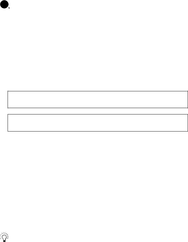
Use the motor's hanging bolts only when transporting the motor. Do not transport the machine when the motor is installed on the machine.
Do not stack the products above the tolerable number.
Follow this manual and install the unit or motor in a place where the weight can be borne.
Do not get on top of or place heavy objects on the unit.
Do not hold the cables, axis or detector when transporting the motor.
Do not hold the connected wires or cables when transporting the units.
Do not hold the front cover when transporting the unit. The unit could drop.
Always observe the installation directions of the units or motors.
Secure the specified distance between the units and control panel, or between the servo drive unit and other devices.
Do not install or run a unit or motor that is damaged or missing parts.
Do not block the intake or exhaust ports of the motor provided with a cooling fan.
Do not let foreign objects enter the units or motors. In particular, if conductive objects such as screws or metal chips, etc., or combustible materials such as oil enter, rupture or breakage could occur.
The units and motors are precision devices, so do not drop them or apply strong impacts to them.
CAUTION
Store and use the units under the following environment conditions.
Environment |
Unit |
Motor |
|
|
|
|
|
Ambient |
Operation: 0 to 55°C (with no freezing), |
Operation: 0 to 40°C (with no freezing), |
|
Storage / Transportation: -15°C to 70°C |
|||
temperature |
Storage: -15°C to 70°C (Note 2) (with no freezing) |
||
|
(with no freezing) |
|
|
|
Operation: 90%RH or less |
Operation: 80%RH or less |
|
Ambient |
(with no dew condensation) |
(with no dew condensation), |
|
humidity |
Storage / Transportation: 90%RH or less |
Storage: 90%RH or less |
|
|
(with no dew condensation) |
(with no dew condensation) |
|
Atmosphere |
Indoors (no direct sunlight) |
||
With no corrosive gas, inflammable gas, oil mist, dust or conductive fine particles |
|||
|
|||
|
Operation/Storage: 1000 meters or less above |
|
|
Altitude |
sea level, |
Operation: 1000 meters or less above sea level, |
|
Transportation: 13000 meters or less above sea |
Storage: 10000 meters or less above sea level |
||
|
|||
|
level |
|
|
Vibration/impact |
According to each unit or motor specification |
||
(Note 1) For details, confirm each unit or motor specifications in addition. (Note 2) -15°C to 55°C for linear servomotor.
Securely fix the servomotor to the machine. Insufficient fixing could lead to the servomotor slipping off during operation.
Always install the servomotor with reduction gear in the designated direction. Failure to do so could lead to oil leaks.
Structure the rotary sections of the motor so that it can never be touched during operation. Install a cover, etc., on the shaft.
When installing a coupling to a servomotor shaft end, do not apply an impact by hammering, etc. The detector could be damaged.
Do not apply a load exceeding the tolerable load onto the servomotor shaft. The shaft could break.
Store the motor in the package box.
When inserting the shaft into the built-in IPM motor, do not heat the rotor higher than 130°C. The magnet could be demagnetized, and the specifications characteristics will not be ensured.
Always use a nonmagnetic tool (explosion-proof beryllium copper alloy safety tool: NGK Insulators, etc.) when installing the linear servomotor.
Always provide a mechanical stopper on the end of the linear servomotor's travel path.
If the unit has been stored for a long time, always check the operation before starting actual operation. Please contact the Service Center, Service Station, Sales Office or delayer.

CAUTION
(2) Wiring
Correctly and securely perform the wiring. Failure to do so could lead to abnormal operation of the motor.
Do not install a condensing capacitor, surge absorber or radio noise filter on the output side of the drive unit.
Correctly connect the output side of the drive unit (terminals U, V, W). Failure to do so could lead to abnormal operation of the motor.
When using a power regenerative power supply unit, always install an AC reactor for each power supply unit.
In the main circuit power supply side of the unit, always install an appropriate circuit protector or contactor for each unit. Circuit protector or contactor cannot be shared by several units.
Always connect the motor to the drive unit's output terminals (U, V, W).
Do not directly connect a commercial power supply to the servomotor. Failure to observe this could result in a fault.
When using an inductive load such as a relay, always connect a diode as a noise measure parallel to the load.
When using a capacitance load such as a lamp, always connect a protective resistor as a noise measure serial to the load.
Do not reverse the direction of a diode which connect to a DC relay for the control output signals such as contractor and motor brake output, etc. to suppress a surge. Connecting it backwards could cause the drive unit to malfunction so that signals are not output, and emergency stop and other safety circuits are inoperable.
Servodrive unit
COM |
|
|
(24VDC) |
|
|
Control output |
RA |
|
signal |
||
|
Servodrive unit |
|
|
COM |
|
|
(24VDC) |
|
|
Control output |
RA |
|
signal |
||
|
Do not connect/disconnect the cables connected between the units while the power is ON.
Securely tighten the cable connector fixing screw or fixing mechanism. An insecure fixing could cause the cable to fall off while the power is ON.
When using a shielded cable instructed in the instruction manual, always ground the cable with a cable clamp, etc.
Always separate the signals wires from the drive wire and power line.
Use wires and cables that have a wire diameter, heat resistance and flexibility that conforms to the system.

CAUTION
(3) Trial operation and adjustment
Check and adjust each program and parameter before starting operation. Failure to do so could lead to unforeseen operation of the machine.
Do not make remarkable adjustments and changes of parameter as the operation could become unstable.
The usable motor and unit combination is predetermined. Always check the models before starting trial operation.
If the axis is unbalanced due to gravity, etc., balance the axis using a counterbalance, etc.
The linear servomotor does not have a stopping device such as magnetic brakes. Install a stopping device on the machine side.
(4) Usage methods
In abnormal state, install an external emergency stop circuit so that the operation can be stopped and power shut off immediately.
Turn the power OFF immediately if smoke, abnormal noise or odors are generated from the unit or motor.
Do not disassemble or repair this product. Never make modifications.
When an alarm occurs, the machine will start suddenly if an alarm reset (RST) is carried out while an operation start signal (ST) is being input. Always confirm that the operation signal is OFF before carrying out an alarm reset. Failure to do so could lead to accidents or injuries.
Reduce magnetic damage by installing a noise filter. The electronic devices used near the unit could be affected by magnetic noise. Install a line noise filter, etc., if there is a risk of magnetic noise.
Use the unit, motor and regenerative resistor with the designated combination. Failure to do so could lead to fires or trouble.
The brake (magnetic brake) of the servomotor are for holding, and must not be used for normal braking.
There may be cases when holding is not possible due to the magnetic brake's life, the machine construction (when ball screw and servomotor are coupled via a timing belt, etc.) or the magnetic brake’s failure. Install a stop device to ensure safety on the machine side.
After changing the programs/parameters or after maintenance and inspection, always test the operation before starting actual operation.
Do not enter the movable range of the machine during automatic operation. Never place body parts near or touch the spindle during rotation.
Follow the power supply specification conditions given in each specification for the power (input voltage, input frequency, tolerable sudden power failure time, etc.).
Set all bits to "0" if they are indicated as not used or empty in the explanation on the bits.
Do not use the dynamic brakes except during the emergency stop. Continued use of the dynamic brakes could result in brake damage.
If a circuit protector for the main circuit power supply is shared by several units, the circuit protector may not activate when a short-circuit fault occurs in a small capacity unit. This is dangerous, so never share the circuit protector.

CAUTION
(5) Troubleshooting
If a hazardous situation is predicted during power failure or product trouble, use a servomotor with magnetic brakes or install an external brake mechanism.
Use a double circuit configuration that allows the operation circuit for the magnetic brakes to be operated even by the external emergency stop signal.
Shut off with the servomotor brake control output.
Servomotor MBR
Magnetic brake
Shut off with NC brake control PLC output.
EMG
24VDC
Always turn the input power OFF when an alarm occurs.
If an alarm occurs, remove the cause, and secure the safety before resetting the alarm.
Never go near the machine after restoring the power after a power failure, as the machine could start suddenly. (Design the machine so that personal safety can be ensured even if the machine starts suddenly.)
(6) Maintenance, inspection and part replacement
Always backup the programs and parameters before starting maintenance or inspections.
The capacity of the electrolytic capacitor will drop over time due to self-discharging, etc. To prevent secondary disasters due to failures, replacing this part every five years when used under a normal environment is recommended. Contact the Service Center, Service Station, Sales Office or delayer for repairs or part replacement.
Do not perform a megger test (insulation resistance measurement) during inspections.
If the battery low warning is issued, back up the machining programs, tool data and parameters with an input/output unit, and then replace the battery.
Do not short circuit, charge, overheat, incinerate or disassemble the battery.
The heat radiating fin used in some units contains substitute Freon as the refrigerant.Take care not to damage the heat radiating fin during maintenance and replacement work.
(7) Disposal
Do not dispose of this type of unit as general industrial waste. Always contact the Service Center, Service Station, Sales Office or delayer for repairs or part replacement.
Do not disassemble the unit or motor.
Dispose of the battery according to local laws.
Always return the secondary side (magnet side) of the linear servomotor to the Service Center or Service Station.
When incinerating optical communication cable, hydrogen fluoride gas or hydrogen chloride gas which is corrosive and harmful may be generated. For disposal of optical communication cable, request for specialized industrial waste disposal services that has incineration facility for disposing hydrogen fluoride gas or hydrogen chloride gas.
CAUTION
(8) Transportation
The unit and motor are precision parts and must be handled carefully.
According to a United Nations Advisory, the battery unit and battery must be transported according to the rules set forth by the International Civil Aviation Organization (ICAO), International Air Transportation Association (IATA), International Maritime Organization (IMO), and United States Department of Transportation (DOT), etc.
(9) General precautions
The drawings given in this manual show the covers and safety partitions, etc., removed to provide a clearer explanation. Always return the covers or partitions to their respective places before starting operation, and always follow the instructions given in this manual.
{ Treatment of waste {
The following two laws will apply when disposing of this product. Considerations must be made to each law. The following laws are in effect in Japan. Thus, when using this product overseas, the local laws will have a priority. If necessary, indicate or notify these laws to the final user of the product.
1.Requirements for "Law for Promotion of Effective Utilization of Resources"
(1)Recycle as much of this product as possible when finished with use.
(2)When recycling, often parts are sorted into steel scraps and electric parts, etc., and sold to scrap contractors. Mitsubishi recommends sorting the product and selling the members to appropriate contractors.
2.Requirements for "Law for Treatment of Waste and Cleaning"
(1)Mitsubishi recommends recycling and selling the product when no longer needed according to item (1) above. The user should make an effort to reduce waste in this manner.
(2)When disposing a product that cannot be resold, it shall be treated as a waste product.
(3)The treatment of industrial waste must be commissioned to a licensed industrial waste treatment contractor, and appropriate measures, including a manifest control, must be taken.
(4)Batteries correspond to "primary batteries", and must be disposed of according to local disposal laws.
Compliance to European EC Directives
1. European EC Directives
The European EC Directives were issued to unify Standards within the EU Community and to smooth the distribution of products of which the safety is guaranteed. In the EU Community, the attachment of a CE mark (CE marking) to the product being sold is mandatory to indicate that the basic safety conditions of the Machine Directives (issued Jan. 1995), EMC Directives (issued Jan. 1996) and the Low-voltage Directives (issued Jan. 1997) are satisfied. The machines and devices in which the servo is assembled are a target for CE marking.
The servo is a component designed not to function as a single unit but to be used with a combination of machines and devices. Thus, it is not subject to the EMC Directives, and instead the machines and devices in which the servo is assembled are targeted.
This servo complies with the Standards related to the Low-voltage Directives in order to make CE marking of the assembled machines and devices easier. The EMC INSTALLATION GUIDELINES (IB (NA) 67303) which explain the servo amplifier installation method and control panel manufacturing method, etc., has been prepared to make compliance to the EMC Directives easier. Contact Mitsubishi or your dealer for more information.
2. Cautions of compliance
Use the standard servo amplifier and EN Standards compliance part (some standard models are compliant) for the servomotor. In addition to the items described in this instruction manual, observe the items described below.
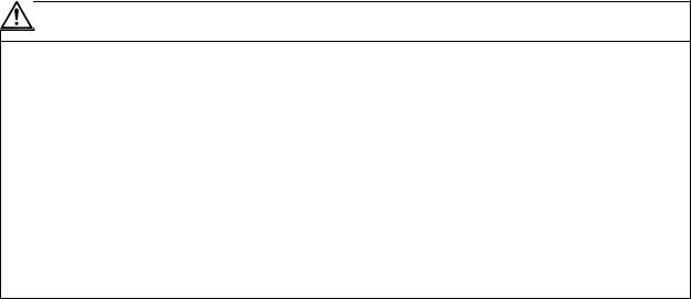
(1) Configuration
Insulation |
Control panel |
|
|
|
transformer |
|
|
|
|
|
|
|
|
|
|
Breaker |
Magnetic |
Servo |
Motor |
|
contactor |
amplifier |
||
|
|
(MC) |
|
|
Use a type B (AC/DC detectable type) breaker
(2)Environment
The servo amplifier must be used within an environment having a Pollution Class 2 or less (Pollution Class 1 or 2) as stipulated in the IEC60664. For this, install the servo amplifier in a control panel having a structure (IP54) into which water, oil, carbon and dust cannot enter.
(3)Power supply
The servo amplifier must be used with the overvoltage category II conditions stipulated in IEC60664. For this, prepare a reinforced insulated transformer that is IEC or EN Standards complying at the power input section.
When supplying the control signal input/output power supply from an external source, use a 24 VDC power supply of which the input and output have been reinforced insulated.
(4)Installation
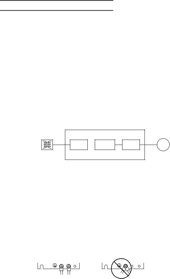
To prevent electric shocks, always connect the servo amplifier protective earth (PE) terminal (terminal with  mark) to the protective earth (PE) on the control panel.
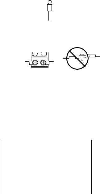
When connecting the earthing wire to the protective earth (PE) terminal, do not tighten the wire terminals together. Always connect one wire to one terminal.
PE terminal |
PE terminal |
(5)Wiring
Always use crimp terminals with insulation tubes so that the wires connected to the servo amplifier terminal block do not contact the neighboring terminals.

 Crimp terminal
 Insulation tube
 Wire
Wire
Connect the HC-MF Series servomotor power lead to the servo amplifier using a fixed terminal block. Do not connect the wires directly. (EN standards compliance parts of the HA-FF motor have cannon plug specifications.)
(6)Peripheral devices
Use a circuit protector and magnetic contactor that comply with the EN/IEC Standards described in Chapter 7 Peripheral Devices.
The wires sizes must follow the conditions below. When using other conditions, follow Table 5 of EN60204-1 Appendix C.
•Ambient temperature: 40°C
•Sheath: PVC (polyvinyl chloride)
•Install on wall without duct or conduit
(7)Servomotor
A servomotor that complies with the EN Standards as a standard, and an EN Standards compatible part are available.
Motor series name |
EN Standards |
|
compatible part |
||
|
HC Series |
|
|
HC R Series |
|
|
HA Series |
Complies as a standard |
|
HC-SF Series |
|
|
HC-RF Series |
|
|
HA-FF Series |
HA-FF C-UE |
|
HC-MF Series |
HC-MF -UE |
|
HC-MF -S15 |
||
|
Refer to "Chapter 6 Dedicated Options" for the connectors and detector cables, and use the EN Standards compatible parts.
(8)Enforcement of EMC test
The EMC test for a machine or device incorporating a servo amplifier must match the magnetism compatibility (immunity and emission) standards in the state that the working environment and electric device specifications are satisfied.
Refer to the EMC INSTALLATION GUIDELINES (IB (NA) 67303) for the EMC Directive measures for the servo amplifier.
Instruction Manual for Compliance with UL/c-UL Standard
(MDS-B-SVJ2, MDS-B-SPJ2 and MR-J2-CT Series)
The instructions of UL/c-UL listed products are described in this manual. The descriptions of this manual are conditions to meet the UL/c-UL standard for the UL/c-UL listed products. To obtain the best performance, be sure to read this manual carefully before use.
To ensure proper use, be sure to read specification manual carefully for each product before use.
1. Operation surrounding air ambient temperature
The recognized operation ambient temperatures of each unit are as shown in the table below. The recognized operation ambient temperatures are the same as an original product specification for all of the units.
Classification |
Unit name |
operation ambient |
|
temperature |
|||
|
|
||
|
|
|
|
AC servo/ |
Power supply unit |
0~55°C |
|
spindle system |
Servo drive unit |
0~55°C |
|
|
|||
|
Spindle drive unit |
0~55°C |
|
|
Option unit |
0~55°C |
|
|
Battery unit |
0~55°C |
|
|
Servo motor, Spindle motor |
0~40°C |
2. Notes for AC servo/spindle system
2-1 General Precaution
It takes 10 minutes to discharge the bus capacitor. (The capacitor discharge time is one minute for MDS-B-SVJ2-01, 03, 04; two minutes for MDS-B-SVJ2-06 and three minutes for MDS-B-SVJ2-07, 10, 20.) When starting wiring or inspection, shut the power off and wait for more than 15 minutes to avoid a hazard of electrical shock.
2-2 Installation
MDS-B-SVJ2, MDS-B-SPJ2 and MR-J2-CT Series have been approved as the products which have been installed in the electrical enclosure.
The minimum enclosure size is based on 150 percent of each MDS-B-SVJ2, SPJ2 and MR-J2-CT Series combination. And also, design the enclosure so that the ambient temperature in the enclosure is 55°C (131°F) or less, refer to the specifications manual. (MDS-B-SVJ2: BNP-B3937, MDS-B-SPJ2: BNP-B2164, MR-J2-CT: BNP-B3944)
"The user must include the use of a 100 cfm fan spaced 4 in. above the drive."
2-3 Short-circuit ratings
Suitable for use in a circuit capable of delivering not more than 100 kA rms symmetrical amperes, 500 volts maximum.
2-4 Peripheral device
To comply with UL/c-UL Standard, use the peripheral devices which conform to the corresponding standard.
- Fuses
Applicable |
UL Fuse |
UL Voltage |
UL Current |
drive unit |
type |
rating, Vac |
rating, A |
|
|
|
|
MDS-B-SVJ2-01 |
K5 |
250 |
10 |
MDS-B-SVJ2-03 |
K5 |
250 |
10 |
MDS-B-SVJ2-04 |
K5 |
250 |
15 |
MDS-B-SVJ2-06 |
K5 |
250 |
20 |
MDS-B-SVJ2-07 |
K5 |
250 |
20 |
MDS-B-SVJ2-10 |
K5 |
250 |
25 |
MDS-B-SVJ2-20 |
K5 |
250 |
40 |
MDS-B-SPJ2-02 |
K5 |
250 |
10 |
MDS-B-SPJ2-04 |
K5 |
250 |
15 |
MDS-B-SPJ2-075 |
K5 |
250 |
20 |
MDS-B-SPJ2-15 |
K5 |
250 |
40 |
MDS-B-SPJ2-22 |
K5 |
250 |
40 |
MDS-B-SPJ2-37 |
K5 |
250 |
60 |
MDS-B-SPJ2-55 |
K5 |
250 |
90 |
MDS-B-SPJ2-75 |
K5 |
250 |
125 |
MDS-B-SPJ2-110 |
K5 |
250 |
175 |
|
|
|
|
Applicable |
UL Fuse |
UL Voltage |
UL Current |
drive unit |
type |
rating, Vac |
rating, A |
|
|
|
|
MR-J2-10CT |
K5 |
250 |
10 |
MR-J2-20CT |
K5 |
250 |
10 |
MR-J2-40CT |
K5 |
250 |
15 |
MR-J2-60CT |
K5 |
250 |
20 |
MR-J2-70CT |
K5 |
250 |
20 |
MR-J2-100CT |
K5 |
250 |
25 |
MR-J2-200CT |
K5 |
250 |
40 |
MR-J2-350CT |
K5 |
250 |
70 |
- Circuit Breaker for of spindle motor Fan
Select the Circuit Breaker by doubling the spindle motor fan rated. A rush current that is approximately double the rated current will flow, when the fan is started
<Notice>
-For installation in United States, branch circuit protection must be provided, in accordance with the National Electrical Code and any applicable local codes.
-For installation in Canada, branch circuit protection must be provided, in accordance with the Canada Electrical Code and any applicable provincial codes.
2-5 Motor Over Load Protection
Servo drive unit MDS-B-SVJ2, MDS-B-SPJ2 and MR-J2-CT series have each solid state motor over load protection. (The motor full load current is the same as rated current.)
When adjusting the level of motor over load, set the parameter as follows.
2-5-1 MDS-B-SVJ2 Series
|
Para- |
Para- |
Parameter |
Setting procedure |
Standard |
Setting |
|
meter |
meter |
name |
setting |
range |
|
|
No. |
abbr. |
|
value |
||
|
|
|
|
|||
|
|
|
|
|
|
|
|
SV021 |
OLT |
Overload |
Set the time constant for |
60s |
1~300s |
|
|
|
time |
overload detection. |
|
|
|
|
|
constant |
(Unit: 1 second.) |
|
|
|
SV022 |
OLL |
Overload |
Set the overload current |
150% |
1~500 |
|
|
|
detection |
detection level with a |
|
% |
|
|
|
level |
percentage (%) of the |
|
|
|
|
|
|
stall rating. |
|
|
2-5-2 MDS-B-SPJ2 Series |
|
|
|
|||
|
Para- |
Para- |
Parameter |
Setting |
Standard |
Setting |
|
meter |
meter |
name |
procedure |
setting |
range |
|
No. |
abbr. |
value |
|||
|
|
|
|
|||
|
|
|
|
|
|
|
|
SP063 |
OLT |
Overload |
Set the time constant for |
60s |
0~1000 |
|
|
|
time |
overload detection. |
|
s |
|
|
|
constant |
(Unit: 1 second.) |
|
|
|
SP064 |
OLL |
Overload |
Set the overload current |
120% |
0~200 |
|
|
|
detection |
detection level with a |
|
% |
|
|
|
level |
percentage (%) of the |
|
|
|
|
|
|
rating. |
|
|
2-5-3 MR-J2-CT Series
The overload current detection level is 150% of the rated current.

2-6 Flange of servo motor
Mount the servo motor on a flange which has the following size or produces an equivalent or higher heat dissipation effect:
Flange size |
|
|
Servo motor |
|
|
||
(mm) |
HC |
HC-RF |
HC-MF |
|
HA-FF |
HC-SF |
|
|
|
|
|
|
|
|
|
150x150x6 |
- |
- |
|
under |
|
under |
- |
|
100W |
|
100W |
||||
|
|
|
|
|
|
||
250x250x6 |
- |
- |
|
200W |
|
200, |
- |
|
|
300W |
|||||
|
|
|
|
|
|
|
|
250x250x12 |
0.5~ |
1.0~ |
|
400W |
|
400,600W |
0.5~ |
1.5kW |
2.0kW |
|
|
1.5kW |
|||
|
|
|
|
|
|||
300x300x12 |
- |
- |
|
750W |
|
- |
- |
300x300x20 |
2.0kW |
- |
|
- |
|
- |
2.0kW |
2-7 Field Wiring Reference Table for Input and Output
Use the UL-approved Round Crimping Terminals to wire the input and output terminals of MDS-B-SVJ2, MDS-B-SPJ2 and MR-J2-CT Series. Crimp the terminals with the crimping tool recommended by the terminal manufacturer.
Following described crimping terminals and tools type is example of Japan Solderless Terminal Mfg. Co., Ltd.
2-7-1 Servo Drive Unit (MDS-B-SVJ2 Series)
Capacity [kW] |
0.1 0.7 |
1.0 |
2.0 |
||
|
|
|
|
|
|
|
D, C, P, N |
Note 1 |
M4 |
M4 |
|
|
Screw torque |
5.3/0.6 |
11/1.3 |
11/1.3 |
|
|
[Ib in/ N m] |
||||
|
|
|
|
||
|
L11, L21 |
Note 1 |
M4 |
M4 |
|
Terminal |
Screw torque |
5.3/0.6 |
11/1.3 |
11/1.3 |
|
Screw Size |
[lb in/ N m] |
||||
|
|
|
|||
|
|
|
|
|
|
|
U, V, W, |
M4 |
M4 |
M4 |
|
|
L1,L2,L3 |
|
|
|
|
|
Screw torque |
11/1.3 |
11/1.3 |
11/1.3 |
|
|
[lb in/ N m] |
||||
|
|
|
|
||
Note1 Control circuit terminal block (MDS-B-SVJ2-01 07)
|
Terminal |
|
Wire size |
|
Terminal bar model |
Crimping |
||||||
|
|
|
(AWG) |
|
Single-wire |
|
Double-wire |
tools type |
||||
|
|
|
|
|
|
|
|
|
|
|
||
|
D, C, P |
|
#14/75 |
|
AI2.5-8BU |
|
AI-TWIN2x2.5-10BU |
CRIMPFOX- |
||||
|
L11, L21 |
|
|
AI2.5-8BU-1000 |
|
AI-TWIN2x2.5-13BU |
UD6 |
|||||
|
|
|
|
|
|
|
|
|
|
|||
|
Crimping terminals and tools type are example of Phoenix-contact |
|||||||||||
L11, L21 |
|
|
|
|
|
|
|
D, C, P |
|
|||
|
Capacity [kW] |
|
1.0, 2.0 |
|
|
|
Capacity [kW] |
|
1.0, 2.0 |
|||
|
|
|
|
|
|
|
|
|
||||
|
Wire Size (AWG) |
|
#14/60 |
|
|
Wire Size (AWG) |
|
#14/60 |
||||
|
/Temp rating |
|
#14/75 |
|
|
|
/Temp rating |
|
#14/75 |
|||
|
Note 2 |
|
|
|
|
Note 2 |
|
|||||
|
|
|
|
|
|
|
|
|
||||
|
Crimping |
|
|
V2-4 |
|
|
|
Crimping |
|
R2-4 |
||
|
terminals type |
|
|
|
|
|
terminals type |
|
||||
|
|
|
|
|
|
|
|
|
||||
|
Crimping tools |
|
YNT-1614 |
|
|
|
Crimping tools |
|
YHT-2210 |
|||
|
type |
|
|
|
|
|
type |
|
||||
|
|
|
|
|
|
|
|
|
|
|||
L1, L2, L3 |
|
|
|
|
|
|
|
U, V, W |
|
|||
|
Capacity [kW] |
|
|
0.1 2.0 |
|
|
|
Capacity [kW] |
|
0.1 2.0 |
||
|
|
|
|
|
|
|
||||||
|
Wire size (AWG) |
|
#14/60 |
|
|
Wire size (AWG) |
|
#14/60 |
||||
|
/Temp rating |
|
#14/75 |
|
|
|
/Temp rating |
|
#14/75 |
|||
|
Note 2 |
|
|
|
|
Note 2 |
|
|||||
|
|
|
|
|
|
|
|
|
||||
|
Crimping |
|
|
R2-4 |
|
|
|
Crimping |
|
R2-4 |
||
|
terminals type |
|
|
|
|
|
terminals type |
|
||||
|
|
|
|
|
|
|
|
|
||||
|
Crimping tools |
|
YHT-2210 |
|
|
|
Crimping tools |
|
YHT-2210 |
|||
|
type |
|
|
|
|
|
type |
|
||||
|
|
|
|
|
|
|
|
|
|
|||
|
Earth wire size |
|
#14/60 |
|
|
|
Earth wire size |
|
#14/60 |
|||
|
(AWG) |
|
#14/75 |
|
|
|
(AWG) |
|
#14/75 |
|||
Note 2 75°C : Grade heat-resistant polyvinyl chloride insulated wires (HIV)
Use copper wire only.
Above listed wire are for use in the electric cabinet on machine or equipment.
2-7-2 Spindle Drive Unit (MDS-B-SPJ2)
Capacity [kW] |
0.2 0.75 |
1.5 3.7 |
5.5 11.0 |
||
|
|
|
|
|
|
|
|
|
|
|
|
|
D, C, P, N |
Note1 |
M4 |
M4 |
|
|
|
|
|
|
|
|
Screw torque |
5.3/0.6 |
10.4/1.2 |
10.4/1.2 |
|
|
[Ib in/ N m] |
||||
|
|
|
|
||
Terminal |
L11, L21 |
Note1 |
M4 |
M4 |
|
Screw torque |
5.3/0.6 |
10.4/1.2 |
17.4/2.0 |
||
screw size |
[lb in/ N m] |
||||
|
|
|
|||
|
U, V, W, |
M4 |
M4 |
M4 |
|
|
L1,L2,L3 |
|
|
|
|
|
Screw torque |
10.4/1.2 |
10.4/1.2 |
10.4/1.2 |
|
|
[lb in/ N m] |
||||
|
|
|
|
||
Note1 Control circuit terminal block (MDS-B-SPJ2-02 075)
Terminal |
Wire size |
Terminal bar model |
Crimping |
|
|
(AWG) |
Single-wire |
Double-wire |
tools type |
|
|
|
|
|
D, C, P |
#14/75 |
AI2.5-8BU |
AI-TWIN2x2.5-10BU |
CRIMPFOX- |
L11, L21 |
AI2.5-8BU-1000 |
AI-TWIN2x2.5-13BU |
UD6 |
|
|
|
|
|
|
Crimping terminals and tools type are example of Phoenix-contact.
L11, L21 |
|
|
|
|
|
|
Capacity [kW] |
1.5 11.0 |
|
|
|
|
|
|
|
|
|
|
Wire size (AWG) |
#14/60 |
|
|
|
|
/Temp rating Note 2 |
#14/75 |
|
|
|
|
Crimping terminals |
V2-4 |
|
|
|
|
type |
|
|
|
|
|
|
|
|
|
|
|
Crimping tools type |
YNT-1614 |
|
|
|
D, C, P |
|
|
|
|
|
|
Capacity [kW] |
1.5 |
2.2 11.0 |
|
|
|
|
|
|
|
|
|
Wire Size (AWG) |
#14/60 |
#12/60 |
|
|
|
/Temp rating Note 2 |
#14/75 |
#14/75 |
|
|
|
Crimping terminals |
R2-4 |
5.5-S4 |
|
|
|
type |
|
|
||
|
|
|
|
|
|
|
Crimping tools type |
YHT- |
2210 |
|
|
L1, L2, L3 |
|
|
|
|
|
|
Capacity [kW] |
0.2 3.7 |
5.5 |
7.5 |
11.0 |
|
|
|
|
|
|
|
Wire Size (AWG) |
#14/60 |
#12/60 |
#10/60 |
#8/60 |
|
/Temp rating Note 2 |
#14/75 |
#12/75 |
#10/75 |
#8/75 |
|
|
||||
|
Crimping terminals |
R2-4 |
5.5-S4 |
5.5-S4 |
TU8-4 |
|
type |
||||
|
|
|
|
|
|
|
Crimping tools type |
|
YHT-2210 |
|
YHT-8S |
|
Earth wire size |
#14/60 |
#12/60 |
#10/60 |
#8/60 |
|
(AWG) |
#14/75 |
#12/75 |
#10/75 |
#8/75 |
U, V, W |
|
|
|
|
|
|
Capacity [kW] |
0.2 3.7 |
5.5 |
7.5 |
11.0 |
|
|
|
|
|
|
|
Wire size (AWG) |
#14/60 |
#12/60 |
#10/60 |
#8/60 |
|
/Temp rating Note 2 |
#14/75 |
#12/75 |
#10/75 |
#8/75 |
|
|
||||
|
Crimping terminals |
R2-4 |
5.5-S4 |
5.5-S4 |
TU8-4 |
|
type |
||||
|
|
|
|
|
|
|
Crimping tools type |
|
YHT-2210 |
|
YHT-8S |
|
Earth wire size |
#14/60 |
#12/60 |
#10/60 |
#8/60 |
|
(AWG) |
#14/75 |
#12/75 |
#10/75 |
#8/75 |
Note 2 75°C : Grade heat-resistant polyvinyl chloride insulated wires (HIV)
Use copper wire only.
Above listed wire are for use in the electric cabinet on machine or equipment.
2-7-3 Servo Drive Unit (MR-J2-CT Series)
Capacity [kW] |
0.1 1.0 |
2.0 |
3.5 |
||
|
|
|
|
|
|
|
|
|
|
|
|
|
D, C, P, N |
Note 1 |
M4 |
M4 |
|
|
Screw torque |
5.3/0.6 |
11/1.3 |
11/1.3 |
|
|
[Ib in/ N m] |
||||
|
|
|
|
||
|
L11, L21 |
Note 1 |
M4 |
M4 |
|
Terminal |
Screw torque |
5.3/0.6 |
11/1.3 |
11/1.3 |
|
screw size |
[lb in/ N m] |
||||
|
|
|
|||
|
|
|
|
|
|
|
U, V, W, |
M4 |
M4 |
M4 |
|
|
L1,L2,L3 |
|
|
|
|
|
Screw torque |
11/1.3 |
11/1.3 |
11/1.3 |
|
|
[lb in/ N m] |
||||
|
|
|
|
||
Note1 Control circuit terminal block (MR-J2-10 100)
|
Terminal |
|
Wire size |
|
Terminal bar model |
Crimping |
||||||
|
|
|
(AWG) |
|
Single-wire |
|
Double-wire |
tools type |
||||
|
|
|
|
|
|
|
|
|
|
|
||
|
D, C, P |
|
#14/75 |
|
AI2.5-8BU |
|
AI-TWIN2x2.5-10BU |
CRIMPFOX- |
||||
|
L11, L21 |
|
|
AI2.5-8BU-1000 |
|
AI-TWIN2x2.5-13BU |
UD6 |
|||||
|
|
|
|
|
|
|
|
|
|
|||
|
Crimping terminals and tools type are example of Phoenix-contact |
|||||||||||
L11, L21 |
|
|
|
|
|
|
|
D, C, P |
|
|||
|
Capacity [kW] |
|
2.0 , 3.5 |
|
|
|
Capacity [kW] |
|
2.0 , 3.5 |
|||
|
|
|
|
|
|
|
|
|
|
|||
|
Wire size (AWG) |
|
#14/60 |
|
|
Wire size (AWG) |
|
#14/60 |
||||
|
/Temp rating |
|
|
|
|
/Temp rating |
|
|||||
|
|
|
|
|
|
|
|
|
||||
|
Note 2 |
|
#14/75 |
|
|
|
Note 2 |
|
#14/75 |
|||
|
Crimping |
|
|
V2-4 |
|
|
|
Crimping |
|
R2-4 |
||
|
terminals type |
|
|
|
|
|
terminals type |
|
||||
|
|
|
|
|
|
|
|
|
||||
|
Crimping tools |
|
YNT-1614 |
|
|
|
Crimping tools |
|
YHT-2210 |
|||
|
type |
|
|
|
|
|
type |
|
||||
|
|
|
|
|
|
|
|
|
|
|||
L1, L2, L3 |
|
|
|
|
|
|
|
U, V, W |
|
|||
Capacity [kW] |
0.1 2.0 |
3.5 |
|
|
|
|
|
Wire size |
#14/60 |
#10/60 |
|
(AWG) |
|||
|
|
||
/Temp rating |
#14/75 |
#10/75 |
|
Note 2 |
|||
|
|
|
|
Crimping |
R2-4 |
5.5-S4 |
|
terminals type |
|||
|
|
||
|
|
|
|
Crimping tools |
YHT-2210 |
||
type |
|||
|
|
||
|
|
||
Earth wire size |
#14/60 |
#12/60 |
|
(AWG) |
#14/75 |
#12/75 |
|
|
|||
Capacity [kW] |
0.1 2.0 |
3.5 |
|
|
|
|
|
Wire size (AWG) |
#14/60 |
#10/60 |
|
/Temp rating |
|
|
|
Note 2 |
#14/75 |
#10/75 |
|
|
|||
|
|
|
|
Crimping |
R2-4 |
5.5-S4 |
|
terminals type |
|||
|
|
||
|
|
|
|
Crimping tools |
YHT-2210 |
||
type |
|||
|
|
||
|
|
||
Earth wire size |
#14/60 |
#12/60 |
|
(AWG) |
#14/75 |
#12/75 |
|
|
|||
Note 2 75°C : Grade heat-resistant polyvinyl chloride insulated wires (HIV)
Use copper wire only.
Above listed wire are for use in the electric cabinet on machine or equipment.
2-8 Spindle Drive / Motor Combinations
Following combinations are the Standard combinations
Applicable spindle motor (kW) |
|
Drive unit |
SJ-PF Series |
SJ-P Series |
|
MDS-B-SPJ2-02 |
0.2 |
|
MDS-B-SPJ2-04 |
0.4 |
|
MDS-SPJ2-075 |
0.75 |
0.75 |
MDS-B-SPJ2-15 |
1.5 |
1.5 |
MDS-B-SPJ2-22 |
2.2 |
2.2 |
MDS-B-SPJ2-37 |
3.7 |
3.7 |
MDS-B-SPJ2-55 |
|
5.5 |
MDS-B-SPJ2-75 |
|
5.5, 7.5 |
MDS-B-SPJ2-110 |
|
7.5, 11 |

3. AC Servo/Spindle System Connection |
|
|
MDS-B-SVJ2 |
|
|
/MDS-B-SPJ2 |
|
|
/MR-J2-CT |
|
|
CN1A CN1B |
|
|
From NC |
|
|
Regarding the connection of |
|
|
NC, see the NC manual book. |
|
|
CN2 |
|
|
CB |
Note: It recommends installing. |
|
L11/L21 |
|
|
CN3 |
|
|
Relay |
Refer to the following specification manuals. |
|
U,V,W L1,L2,L3 |
||
MDS-B-SVJ2: BNP-B3937 |
||
|
||
|
MDS-B-SPJ2: BNP-B2164 |
|
|
MR-J2-CT: BNP-B3944 |
|
MC |
Fuse |
|
|
||
Contactor |
or |
|
Circuit Breaker |
||
|
|
3 phases |
|
Enclosure Side |
200 to 230Vac |
|
Input |
||
|
||
Machine Side |
Servo / Spindle Motor |
|
|
||
|
Encoder |
Compliance to Transportation Restrictions for Lithium Batteries
1. Restriction for packing
The United Nations Dangerous Goods Regulations "Article 12" became effective from 2003. When transporting lithium batteries with means subject to the UN Regulations, such as by air transport, measures corresponding to the Regulations must be taken. The UN Regulations classify the batteries as dangerous goods (Class 9) or not dangerous goods according to the lithium content.
To ensure safety during transportation, lithium batteries (battery unit) directly exported from Mitsubishi are packaged in a dedicated container (UN package) for which safety has been confirmed. When the customer is transporting these products with means subject to the UN Regulations, such as air transport, the shipper must follow the details explained in the section "1-2 Handling by user".
1-1 Target products
The following Mitsubishi NC products use lithium batteries. The UN Regulations classify the batteries as dangerous goods (Class 9) or not dangerous goods according to the lithium content. If the batteries subjected to hazardous materials are incorporated in a device and shipped, a dedicated packaging (UN packaging) is not required. However, the item must be packed and shipped following the Packing Instruction 912 specified in the IATA DGR (Dangerous Goods Regulation) book.
Also, all lithium battery products incorporated in a machinery or device must be fixed securely in accordance with the Packing Instruction 900 and shipped with protection in a way as to prevent damage or short-circuits.
(1) Products requiring dedicated packaging (Materials falling under Class 9)
Mitsubishi type |
|
Lithium metal |
|
|
Outline dimension |
|
(Type for |
Battery type |
Application |
Battery class |
|||
content |
drawing |
|||||
arrangement) |
|
|
|
|||
|
|
|
|
|
MDS-A-BT-4
MDS-A-BT-6
MDS-A-BT-8
FCU6-BT4-D1
CR23500SE-CJ5 (Note1)
ER6-B4-11 |
2.6g |
For servo |
|
ER6-B6-11 |
3.9g |
For servo |
Battery |
ER6-B8-11 |
5.2g |
For servo |
|
Combination of |
2.6g+0.65g |
For NC/ servo |
|
ER6-B4D-11 and ER6 |
|
||
|
|
|
|
CR23500SE-CJ5 |
1.52g |
For NC(M500) |
Battery cell |
|
|
|
|
For each outline dimension drawing of servo, refer to the section “6-2 Battery option”.
(2) Products not requiring dedicated packaging (Materials not falling under Class 9)
Mitsubishi type |
|
Lithium metal |
|
|
Outline dimension |
|
(Type for |
Battery type |
Application |
Battery class |
|||
content |
drawing |
|||||
arrangement) |
|
|
|
|||
|
|
|
|
|
MDS-A-BT-2 |
ER6-B2-12 |
1.3g |
For servo |
Battery |
|
FCU6-BTBOX series |
2CR5 |
1.96g |
For NC/ servo |
||
|
|||||
CR2032 |
CR2032 |
0.067g |
For NC |
|
|
(for built-in battery) |
|
||||
|
|
|
|
||
CR2450 |
CR2450 |
0.173g |
For NC |
|
|
(for built-in battery) |
|
||||
|
|
|
Battery cell |
||
ER6, ER6V series |
ER6, ER6V |
0.7g |
For NC/servo |
||
(for built-in battery) |
|
||||
|
|
|
|
||
A6BAT (MR-BAT) |
ER17330V |
0.48g |
For servo |
|
|
Q6BAT |
Q6BAT |
0.49g |
For NC |
|
|
MR-J3BAT |
ER6V |
0.65g |
For servo |
|
For each outline dimension drawing of servo, refer to the section “6-2 Battery option”.
(Note 1) When CR23500SE-CJ5 is incorporated in the unit, this battery is not subject to the regulation.
(Note 2) Dedicated packaging is required if the shipment exceeds 12 batteries/24 battery cells. Package the batteries so that this limit is not exceeded.
(Note 3) The battery units labeled as "FCUA-" instead of "MDS-A-" also use the same battery.
(Note 4) Always use the cell battery (A6BAT) in combination with the dedicated case (MDS-BTCASE). Maximum 8 (either 2, 4, 6 or 8) cell batteries (A6BAT) can be installed to the dedicated case (MDS-BTCASE).
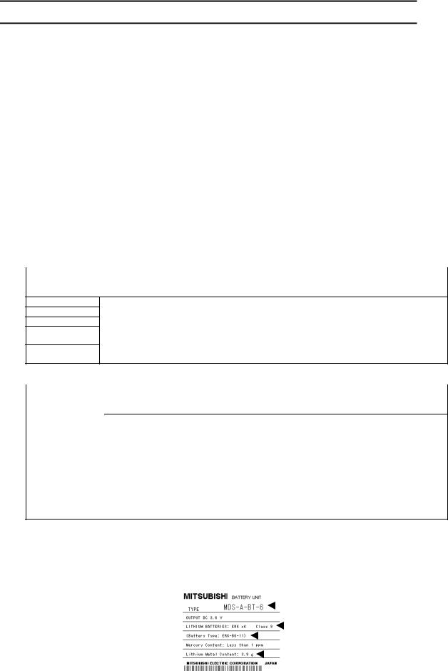
Example) Rating nameplate |
|
|
|
|
|
|
|
|
for battery units |
|
|
|
|
|
|
|
Mitsubishi type |
|
|
|
|
|
|
|
||
|
|
|
|
|
|
|
|
Safety class |
|
|
|
|
|
|
|
||
|
|
|
|
|
|
|
|
Battery manufacturer type |
|
|
|
|
|
|
|
|
|
|
|
|
|
|
|
|
|
Lithium metal content |
|
|
|
|
|
|
|
|
|
|
|
|
|
|
|
|
|
|

1-2 Handling by user
The following technical opinion is solely Mitsubishi's opinion. The shipper must confirm the latest IATA Dangerous Goods Regulations, IMDG Codes and laws and orders of the corresponding export country. These should be checked by the company commissioned for the actual transportation.
IATA |
: International Air Transport Association |
IMDG Code |
: A uniform international code for the transport of dangerous goods by seas |
|
determined by IMO (International Maritime Organization). |
■ When shipping isolated lithium battery products (Packing Instruction 903)
(1) Reshipping in Mitsubishi UN packaging
Mitsubishi packing applies the isolated battery's safety test and packaging specifications complying with the UN Regulations (Packing Instruction 903).
The user only needs to add the following details before shipping. (Consult with the shipping company for details.)
(a) Indication of container usage mark on exterior box (Label with following details recorded.)
•Proper shipping name (Lithium batteries)
•UN NO. (UN3090 for isolated battery, UN3091 for battery incorporated in a device or included)
•Shipper and consignee's address and name
Example of completing form
Shipper information |
|
Consignee information |
|
|
|
|
|
|
(b)Preparation of shipping documents (Declaration of dangerous goods)
(Refer to "3. Example of hazardous goods declaration list" in this section.)
(2)When packaged by user
The user must follow UN Regulations when packing, preparing for shipping and preparing the indications, etc.
(a)Packing a lithium battery falling under Class 9
•Consult with The Ship Equipment Inspection Society of Japan for details on packaging.
•Prepare for shipping as explained in "(1) Reshipping in Mitsubishi UN packaging".
The Ship Equipment Inspection Society of Japan
Headquarters Telephone: 03-3261-6611 Fax: 03-3261-6979
(b)Packing a lithium battery not falling under Class 9
•Cells and batteries are separated so as to prevent short circuits and are stored in a strong outer packaging. (12 or less batteries, 24 or less cells.)
•Prepare for the certificates or test results showing compliance to battery safety test. The safety test results have been obtained from the battery manufacturer. (Consult with Mitsubishi when the safety test results are required.)
•Prepare for shipping as explained in "(1) Reshipping in Mitsubishi UN packaging".
■ When shipping lithium batteries upon incorporating in a machinery or device
(Packing Instruction 900)
Pack and prepare for shipping the item in accordance with the Packing Instruction 900 specified in the IATA DGR (Dangerous Goods Regulation) book. (Securely fix the batteries that comply with the UN Manual of Tests and Criteria to a machinery or device, and protect in a way as to prevent damage or short-circuit.)
Note that all the lithium batteries provided by Mitsubishi have cleared the UN recommended safety test; fixing the battery units or cable wirings securely to the machinery or device will be the user’s responsibility.
Check with your shipping company for details on packing and transportation.
■ When shipping a device with lithium batteries incorporated (Packing Instruction 912)
A device incorporating lithium batteries does not require a dedicated packaging (UN packaging). However, the item must be packed, prepared for shipping and labeled following the Packing Instruction 912 specified in the IATA DGR (Dangerous Goods Regulation) book.
Check with your shipping company for details on packing and transportation.
The outline of the Packing Instruction 912 is as follows:
•All the items in the packing instructions for shipping the isolated lithium battery products (Packing Instruction 903) must be satisfied, except for the items related to container, short-circuit, and fixation.
•A device incorporating lithium batteries has to be stored in a strong water-proofed outer packaging.
•To prevent an accidental movement during shipment, securely store the item in an outer packaging.
•Lithium content per device should be not more than 12g for cell and 500g for battery.
•Lithium battery mass per device should be not more than 5kg.
1-3 Reference
Refer to the following materials for details on the regulations and responses.
Guidelines regarding transportation of lithium batteries and lithium ion batteries (Edition 2)
• • • • • Battery Association of Japan

2. Issuing domestic law of the United State for primary lithium battery transportation
Federal Aviation Administration (FAA) and Research and Special Programs Administration (RSPA) announced an additional regulation (interim final rule) for the primary lithium batteries transportation restrictions item in "Federal Register" on Dec.15 2004. This regulation became effective from Dec.29, 2004.
This law is a domestic law of the United States, however if also applies to the domestic flight and international flight departing from or arriving in the United States. Therefore, when transporting lithium batteries to the United State, or within the United State, the shipper must take measures required to transport lithium batteries.
Refer to the Federal Register and the code of Federal Regulation ("2-4 Reference”) for details.
2-1 Outline of regulation
(1) Transporting primary lithium battery by passenger aircraft is forbidden.
• Excluding primary lithium battery for personal use in a carry-on or checked luggage
(Lithium metal content should be not more than 5g for cell and 25g for battery. For details on the lithium metal content, refer to "1-1 Target products".)
(2)When transporting primary lithium battery by cargo aircraft, indicate that transportation by passenger aircraft is forbidden on the exterior box.
2-2 Target products
All NC products for which the lithium batteries are used are subject to the regulation. (Refer to the table "1-1 Target products".)
2-3 Handling by user
The "2-1 Outline of regulation" described above is solely Mitsubishi's opinion. The shipper must confirm orders of "2-4 Reference" described below for transportation method corresponding the regulation. Actually, these should be checked by the company commissioned for the actual lithium buttery transportation.
(1)Indication of exterior box
When transporting primary lithium battery by cargo aircraft, indicate that transportation by passenger aircraft is forbidden on the exterior box.
Display example
PRIMARY LITHIUM BATTERIES
FORBIDDEN FOR TRANSPORT ABOARD PASSENGER AIRCRAFT.
•The character color must be displayed with contrast. (black characters against white background, black characters against yellow background, etc.)
•The height (size) of characters to be displayed is prescribed depending on the packaging mass.
When the total mass is over 30kg: |
at least 12mm |
When the total mass is less than 30kg: |
at least 6mm |
2-4 Reference
(1)Federal Register (Docket No. RSPA-2004-19884 (HM-224E) ) PDF format http://www.regulations.gov/fredpdfs/05-11765.pdf
(2) 49CFR (Code of Federal Regulation, Title49) (173.185 Lithium batteries and cells.) http://www.access.gpo.gov/nara/cfr/waisidx_00/49cfr173_00.html
(3)DOT regulation body (Department of Transportation) http://hazmat.dot.gov/regs/rules/final/69fr/docs/69fr-75207.pdf
3. Example of hazardous goods declaration list
This section describes a general example of the hazardous goods declaration list. For details, please inquire each transportation company.
This will be applied only to the batteries described in "1. Restriction for Packing".
(1) |
Outline of hazard |
|
|
|||
|
|
|
|
|
||
|
Principal hazard and effect |
Not found. |
|
|||
|
Specific hazard |
As the chemical substance is stored in a sealed metal container, the battery itself is |
|
|||
|
|
|
|
|
not hazardous. But when the internal lithium metal attaches to human skin, it |
|
|
|
|
|
|
causes a chemical skin burn. As a reaction of lithium with water, it may ignite or |
|
|
|
|
|
|
forms flammable hydrogen gas. |
|
|
Environmental effect |
Not found. |
|
|||
|
Possible state of emergency |
Damages or short-circuits may occur due to external mechanical or electrical |
|
|||
|
|
|
|
|
pressures. |
|
(2) First-aid measure |
|
|
||||
|
|
|
|
|
|
|
|
Inhalation |
|
If a person inhales the vapor of the substance due to the battery damage, move the |
|
||
|
|
|
|
|
person immediately to fresh air. If the person feels sick, consult a doctor |
|
|
|
|
|
|
immediately. |
|
|
Skin contact |
|
If the content of the battery attaches to human skin, wash off immediately with |
|
||
|
|
|
|
|
water and soap. If skin irritation persists, consult a doctor. |
|
|
Eye contact |
|
In case of contact with eyes due to the battery damage, rinse immediately with a |
|
||
|
|
|
|
|
plenty of water for at least 15 minutes and then consult a doctor. |
|
|
Ingestion |
|
If swallowed, consult a doctor immediately. |
|
||
(3) Fire-fighting measure |
|
|
||||
|
|
|
|
|
||
|
Appropriate fire-extinguisher |
Dry sand, dry chemical, graphite powder or carbon dioxide gas |
|
|||
|
Special fire-fighting measure |
Keep the battery away from the fireplace to prevent fire spreading. |
|
|||
|
Protectors against fire |
Fire-protection gloves, eye/face protector (face mask), body/skin protective cloth |
|
|||
(4) |
Measure for leakage |
|
|
|||
|
|
|
|
|
||
|
Environmental precaution |
Dispose of them immediately because strong odors are produced when left for a |
|
|||
|
|
|
|
|
long time. |
|
|
How to remove |
Get them absorbed into dry sand and then collect the sand in an empty container. |
|
|||
(5) |
Handling and storage |
|
|
|||
|
|
|
|
|
|
|
|
|
|
|
Cautions for safety |
Do not peel the external tube or damage it. |
|
|
|
|
|
handling |
Do not dispose of the battery in fire or expose it to heat. |
|
|
Handling |
|
|
Do not immerse the battery in water or get it wet. |
|
|
|
|
|
Do not throw the battery. |
|
||
|
|
|
|
|
|
|
|
|
|
|
|
Do not disassemble, modify or transform the battery. |
|
|
|
|
|
|
Do not short-circuit the battery. |
|
|
|
|
|
Appropriate storage |
Avoid direct sunlight, high temperature and high humidity. |
|
|
Storage |
|
condition |
(Recommended temp. range: +5 to +35 oC, humidity: 70%RH or less) |
|
|
|
|
|
|
Material to avoid |
Flammable or conductive material (Metal: may cause a short-circuit) |
|
(6) |
Physical/chemical properties |
|
||||
|
|
|
|
|
|
|
|
|
|
|
Physical form |
Solid |
|
|
|
|
|
Shape |
Cylinder type |
|
|
|
|
|
Smell |
Odorless |
|
|
Appear- |
|
pH |
Not applicable (insoluble) |
|
|
|
|
Boiling point/Boiling |
No information |
|
||
|
ance |
|
|
|||
|
|
range, |
|
|
||
|
|
|
|
|
|
|
|
|
|
|
Melting point, |
|
|
|
|
|
|
Decomposition |
|
|
|
|
|
|
temperature, |
|
|
|
|
|
|
Flash point |
|
|
(7) Stability and reactivity
Stability |
Stable under normal handling condition. |
Condition to avoid |
Do not mix multiple batteries with their terminals uninsulated. This may cause a |
|
short-circuit, resulting in heating, bursting or ignition. |
Hazardous decomposition |
Irritative or toxic gas is emitted in the case of fire. |
products |
|
(8) Toxicological information
As the chemical substance is stored in a sealed metal container, the battery has no harmfulness. Just for reference, the table below describes the main substance of the battery.
(Lithium metal)
Acute toxicity |
No information |
Local effect |
Corrosive action in case of skin contact |
(9) Ecological information
Mobility, |
Not found. |
Persistence/Decomposability, |
|
Bio-accumulation potential, |
|
Ecological toxicity |
|
(10)Caution for disposal
Dispose of the battery following local laws or regulations.
Pack the battery properly to prevent a short-circuit and avoid contact with water.

Compliance with Restrictions in China
1. Compliance with China CCC certification system
1-1 Outline of China CCC certification system
The Safety Certification enforced in China included the "CCIB Certification (certification system based on the "Law of the People’s Republic of China on Import and Export Commodity Inspection" and "Regulations on Implementation of the Import Commodities Subject to the Safety and Quality Licensing System" enforced by the State Administration of Import and Export Commodity Inspection (SACI) on import/export commodities, and the "CCEE Certification" (certification system based on "Product Quality Certification Management Ordinance" set forth by the China Commission for Conformity Certification of Electrical Equipment (CCEE) on commodities distributed through China.
CCIB Certification and CCEE Certification were merged when China joined WTO (November 2001), and were replaced by the "China Compulsory Product Certification" (hereinafter, CCC Certification) monitored by the State General Administration of Quality Supervision, Inspection and Quarantine (AQSIQ) of the People's Republic of China.
The CCC Certification system was partially enforced from May 2002, and was fully enforced from May 2003. Target commodities which do not have CCC Certification cannot be imported to China or sold in China. (Indication of the CCIB or CCEE mark has been eliminated from May 1, 2003.)
CCIB : China Commodity Inspection Bureau
CCEE: China Commission for Conformity Certification of Electrical Equipment CCC : China Compulsory Certification
1-2 First catalogue of products subject to compulsory product certification
The First Catalogue of Products subject to Compulsory Product Certification, covering 132 items (19 categories) based on the CCIB products (104 items), CCEE products (107 items) and CEMC products (Compulsory EMC Certification products) was designated on December 3, 2001.
Class |
|
Product catalogue |
|
|
Class |
Product catalogue |
|
1 |
Electric Wires and Cables (5 items) |
|
|
5 |
Electric tools |
(16 items) |
|
2 |
Switches, Installation protective and connection devices (6 items) |
|
6 |
Welding machines |
(15 items) |
||
3 |
Low-voltage Electrical Apparatus (9 items) |
Compulsory Certification |
|
7 |
Household and similar |
(18 items) |
|
|
|
|
Regulations |
|
|
electrical appliances |
|
|
|
Circuit-breakers (including RCCB, RCBO, MCB) |
|
|
8 |
Audio and video equipment |
(16 items) |
|
|
Low-voltage switchers |
|
|
9 |
Information technology |
(12 items) |
|
|
(disconnectors, switch-disconnectors, and |
|
|
|
equipment |
|
|
|
fuse-combination devices. |
|
|
10 |
Lighting apparatus |
(2 items) |
|
|
|
|
|
11 |
Telecommunication terminal |
(9 items) |
|
|
|
|
|
|
equipment |
|
|
|
Other protective equipment for circuits |
|
|
12 |
Motor vehicles and Safety |
(4 items) |
|
|
(Current limiting devices, circuits protective |
|
|
|
Parts |
|
|
|
devices, over current protective devices, |
|
|
13 |
Tyres |
(4 items) |
|
|
thermal protectors, over load relays, |
|
|
|
|
|
|
|
|
|
14 |
Safety Glasses |
(3 items) |
|
|
|
low-voltage electromechanical contactors and |
|
|
|||
|
|
|
|
15 |
Agricultural Machinery |
(1 item) |
|
|
|
motor starters) |
CNCA -01C -011: 2001 |
|
|||
|
|
|
|
|
|
||
|
|
Relays (36V < Voltage ≤ 1000V) |
|
16 |
Latex Products |
(1 item) |
|
|
|
(Switch and Control |
|
||||
|
|
Other switches |
|
17 |
Medical Devices |
(7 items) |
|
|
|
Equipment) |
|
||||
|
|
(Switches for appliances, vacuum switches, |
CNCA -01C -012: 2001 |
|
18 |
Fire Fighting Equipment |
(3 items) |
|
|
pressure switches, proximity switches, foot |
(Installation Protective |
|
|
|
|
|
|
|
19 |
Detectors for Intruder Alarm |
(1 item) |
||
|
|
switches, thermal sensitive switches, hydraulic |
Equipment) |
|
|
Systems |
|
|
|
switches, push-button switches, position limit |
|
|
|
|
|
|
|
|
|
|
|
|
|
|
|
switches, micro-gap switches, temperature |
|
|
|
|
|
|
|
sensitive switches, travel switches, |
|
|
|
|
|
|
|
change-over switches, auto-change-over |
|
|
|
|
|
|
|
switches, knife switches) |
|
|
|
|
|
|
|
|
|
|
|
|
|
|
|
Other devices |
|
|
|
|
|
|
|
(contactors, motor starters, indicator lights, |
|
|
|
|
|
|
|
auxiliary contact assemblies, master |
|
|
|
|
|
|
|
controllers, A.C. Semiconductor motor |
|
|
|
|
|
|
|
controllers and starters) |
|
|
|
|
|
|
|
Earth leakage protectors |
|
|
|
|
|
|
|
Fuses |
|
|
|
|
|
|
|
Low-voltage switchgear |
CNCA-01C-010:2001 |
|
|
|
|
|
|
|
(Low-voltage |
|
|
|
|
|
|
|
switchgear) |
|
|
|
|
4 |
Small power motors (1 item) |
CNCA-01C-013:2001 |
|
|
|
|
|
(Note) |
|
|
(Small power motors) |
|
|
|
|
(Note) When the servomotor or the spindle motor of which output is 1.1kW or less (at 1500 r/min) is used, NC could have been considered as a small power motor. However, CQC (China Quality Certification Center) judged it is not.
1-3 Precautions for shipping products
As indicated in 1-2, NC products are not included in the First Catalogue of Products subject to Compulsory Product Certification. However, the Customs Officer in China may judge that the product is subject to CCC Certification just based on the HS Code.Note 2
NC cannot be imported if its HS code is used for the product subject to CCC Certification. Thus, the importer must apply for a "Certification of Exemption" with CNCA.Note 3 Refer to 1-4 Application for Exemption for details on applying for an exemption.
(Note 1) The First Catalogue of Products subject to Compulsory Product Certification (Target HS Codes) can be confirmed at http://www.cqc.com.cn/Center/html/60gonggao.htm.
(Note 2) HS Code: Internationally unified code (up to 6 digits) assigned to each product and used for customs.
(Note 3) CNCA: Certification and Accreditation Administration of People's Republic of China (Management and monitoring of certification duties)
Loading...