


 Loading...

 SAFETY PRECAUTIONS
(Please read these instructions before using this equipment.)
Before using this product, please read this manual and the relevant manuals introduced in this manual carefully and pay full attention to safety to handle the product correctly.
These precautions apply only to this product.
In this manual, the safety instructions are ranked as "DANGER" and "CAUTION".

 DANGER

 CAUTION
Indicates that incorrect handling may cause hazardous conditions, resulting in death or severe injury.
Indicates that incorrect handling may cause hazardous conditions, resulting in medium or slight personal injury or physical damage.
Depending on circumstances, procedures indicated by  CAUTION may also be linked to serious results.
In any case, it is important to follow the directions for usage.
Please save this manual to make it accessible when required and always forward it to the end user.
A - 1

For Safe Operations
1. Prevention of electric shocks
 DANGER
 Never open the front case or terminal covers of the servo amplifier while the power is ON or the unit is running, as this may lead to electric shocks.
 Never run the unit with the front case or terminal cover of the servo amplifier removed. The high voltage terminal and charged sections will be exposed and may lead to electric shocks.
 Never open the front case or terminal cover of the servo amplifier at times other than wiring work or periodic inspections even if the power is OFF. The insides of the position board and servo amplifier are charged and may lead to electric shocks.
 Completely turn off the externally supplied power used in the system before mounting or removing the position board, performing wiring work, or inspections. Failing to do so may lead to electric shocks.
 When performing wiring work or inspections, turn the power OFF, wait at least ten minutes, and then check the voltage with a tester, etc. Failing to do so may lead to electric shocks.
 Be sure to ground the controller incorporating the position board, servo amplifier and servo motor. (Ground resistance : 100
  or less) Do not ground commonly with other devices.
 The wiring work and inspections must be done by a qualified technician.
 Wire the units after installing the position board, servo amplifier and servo motor. Failing to do so may lead to electric shocks or damage.
 Never operate the switches with wet hands, as this may lead to electric shocks.
 Do not damage, apply excessive stress, place heavy things on or sandwich the cables, as this may lead to electric shocks.
 Do not touch the position board, servo amplifier or servo motor terminal blocks while the power is ON, as this may lead to electric shocks.
 Do not touch the built-in power supply, built-in grounding or signal wires of the position board and servo amplifier, as this may lead to electric shocks.
2. For fire prevention
 CAUTION
 Install the position board, servo amplifier, servo motor and regenerative resistor on incombustible. Installing them directly or close to combustibles will lead to fire.
 If a fault occurs in the position board or servo amplifier, shut the power OFF at the servo amplifier’s power source. If a large current continues to flow, fire may occur.
 When using a regenerative resistor, shut the power OFF with an error signal. The regenerative resistor may abnormally overheat due to a fault in the regenerative transistor, etc., and may lead to fire.
 Always take heat measures such as flame proofing for the inside of the control panel where the servo amplifier or regenerative resistor is installed and for the wires used. Failing to do so may lead to fire.
 Do not damage, apply excessive stress, place heavy things on or sandwich the cables, as this may lead to fire.
A - 2

3. For injury prevention
 CAUTION
 Do not apply a voltage other than that specified in this manual and the instruction manual of the product you are using on any terminal.
Doing so may lead to destruction or damage.
 Do not mistake the terminal connections, as this may lead to destruction or damage.
 Do not mistake the polarity ( + / - ), as this may lead to destruction or damage.
 Do not touch the heat radiating fins of position board or servo amplifier, regenerative resistor and servo motor, etc., while the power is ON and for a short time after the power is turned OFF. In this timing, these parts become very hot and may lead to burns.
 Always turn the power OFF before touching the servo motor shaft or coupled machines, as these parts may lead to injuries.
 Do not go near the machine during test operations or during operations such as teaching. Doing so may lead to injuries.
4. Various precautions
Strictly observe the following precautions.
Mistaken handling of the unit may lead to faults, injuries or electric shocks.
(1) System structure
 CAUTION
 Always install a leakage breaker on the controller incorporating the position board and servo amplifier power source.
 If installation of an electromagnetic contactor for power shut off during an error, etc., is specified in the instruction manual for the servo amplifier, etc., always install the electromagnetic contactor.
 Install the emergency stop circuit externally so that the operation can be stopped immediately and the power shut off.
 Use the position board, servo amplifier, servo motor and regenerative resistor with the correct combinations listed in the instruction manual. Other combinations may lead to fire or faults.
 If safety standards (ex., robot safety rules, etc.,) apply to the system using the position board, servo amplifier and servo motor, make sure that the safety standards are satisfied.
 Construct a safety circuit externally of the position board or servo amplifier if the abnormal operation of the position board or servo amplifier differ from the safety directive operation in the system.
 In systems where coasting of the servo motor will be a problem during the forced stop, emergency stop, servo OFF or power supply OFF, use dynamic brakes.
 Make sure that the system considers the coasting amount even when using dynamic brakes.
  In systems where perpendicular shaft dropping may be a problem during the forced stop,
emergency stop, servo OFF or power supply OFF, use both dynamic brakes and electromagnetic brakes.
A - 3

 CAUTION
 The dynamic brakes must be used only on errors that cause the forced stop, emergency stop, or servo OFF. These brakes must not be used for normal braking.
 The brakes (electromagnetic brakes) assembled into the servo motor are for holding applications, and must not be used for normal braking.
 The system must have a mechanical allowance so that the machine itself can stop even if the stroke limits switch is passed through at the max. speed.
 Use wires and cables that have a wire diameter, heat resistance and bending resistance compatible with the system.
 Use wires and cables within the length of the range described in the instruction manual.
 The ratings and characteristics of the parts (other than position board, servo amplifier and servo motor) used in a system must be compatible with the position board, servo amplifier and servo motor.
 Install a cover on the shaft so that the rotary parts of the servo motor are not touched during operation.
 There may be some cases where holding by the electromagnetic brakes is not possible due to the life or mechanical structure (when the ball screw and servomotor are connected with a timing belt, etc.). Install a stopping device to ensure safety on the machine side.
(2) Parameter settings and programming
 CAUTION
 Set the parameter values to those that are compatible with the position board, servo amplifier, servo motor and regenerative resistor model and the system application. The protective functions may not function if the settings are incorrect.
 The regenerative resistor model and capacity parameters must be set to values that conform to the operation mode and servo amplifier. The protective functions may not function if the settings are incorrect.
 Set the mechanical brake output and dynamic brake output validity parameters to values that are compatible with the system application. The protective functions may not function if the settings are incorrect.
 Set the stroke limit input validity parameter to a value that is compatible with the system application. The protective functions may not function if the setting is incorrect.
 Set the servo motor encoder type (increment, absolute position type, etc.) parameter to a value that is compatible with the system application. The protective functions may not function if the setting is incorrect.
 Set the servo motor capacity and type (standard, low-inertia, flat, etc.) parameter to values that are compatible with the system application. The protective functions may not function if the settings are incorrect.
 Set the servo amplifier capacity and type parameters to values that are compatible with the system application. The protective functions may not function if the settings are incorrect.
  Use the program commands for the program with the conditions specified in the instruction manual.
A - 4

(3) Transportation and installation
 CAUTION
 Transport the product with the correct method according to the mass.
 Use the servo motor suspension bolts only for the transportation of the servo motor. Do not transport the servo motor with machine installed on it.
 Do not stack products past the limit.
 When transporting, installing, and removing the position board, never touch the print board inner part and electronic components. Hold the front panel or edge of the print board.
 When transporting the position board or servo amplifier, never hold the connected wires or cables.
 When transporting the servo motor, never hold the cables, shaft or detector.
 When transporting the position board or servo amplifier, never hold the front case as it may fall off.
 When transporting, installing or removing the position board or servo amplifier, never hold the edges.
 Install the unit according to the instruction manual in a place where the mass can be withstood.
 Do not get on or place heavy objects on the product.
 Always observe the installation direction.
 Mount the position board to a connector or slot that is compatible with standards, and keep the designated clearance between the position board and other boards.
 Keep the designated clearance between the position board or servo amplifier and control panel inner surface or the position board and servo amplifier, position board or servo amplifier and other devices.
 Do not install or operate position board, servo amplifiers or servo motors that are damaged or that have missing parts.
 Do not block the intake/outtake ports of the servo amplifier and servo motor with cooling fan.
 Do not allow conductive matter such as screw or cutting chips or combustible matter such as oil enter the position board, servo amplifier or servo motor.
 The position board, servo amplifier and servo motor are precision machines, so do not drop or apply strong impacts on them.
 Securely fix the position board, servo amplifier and servo motor to the machine according to the instruction manual. If the fixing is insufficient, these may come off during operation.
A - 5

 CAUTION
 Always install the servo motor with reduction gears in the designated direction. Failing to do so may lead to oil leaks.
 Store and use the unit in the following environmental conditions.
Environment |
Conditions |
|
||
Position board/Servo amplifier |
|
Servomotor |
||
|
|
|||
Ambient |
According to each instruction manual. |
|
0°C to +40°C (With no freezing) |
|
temperature |
|
(32°F to +104°F) |
||
|
|
|||
Ambient humidity |
According to each instruction manual. |
|
80% RH or less |
|
|
(With no dew condensation) |
|||
|
|
|
||
Storage |
According to each instruction manual. |
|
-20°C to +65°C |
|
temperature |
|
(-4°F to +149°F) |
||
|
|
|||
Atmosphere |
Indoors (where not subject to direct sunlight). |
|||
No corrosive gases, flammable gases, oil mist or dust must exist |
||||
|
||||
Altitude |
1000m (3280.84ft.) or less above sea level |
|||
Vibration |
According to each instruction manual |
|||
 When coupling with the synchronous encoder or servo motor shaft end, do not apply impact such as by hitting with a hammer. Doing so may lead to detector damage.
 Do not apply a load larger than the tolerable load onto the synchronous encoder and servo motor shaft. Doing so may lead to shaft breakage.
 When not using for a long time, disconnect the power line from the servo amplifier.
 Place the position board and servo amplifier in static electricity preventing vinyl bags and store.
 When storing for a long time, please contact with our sales representative. Also, execute a trial operation.
 When fumigants that contain halogen materials such as fluorine, chlorine, bromine, and iodine are used for disinfecting and protecting wooden packaging from insects, they cause malfunction when entering our products.
Please take necessary precautions to ensure that remaining materials from fumigant do not enter our products, or treat packaging with methods other than fumigation (heat method). Additionally, disinfect and protect wood from insects before packing products.
A - 6

(4) Wiring
 CAUTION
 Correctly and securely wire the wires. Reconfirm the connections for mistakes and the terminal screws for tightness after wiring. Failing to do so may lead to run away of the servo motor.
 After wiring, install the protective covers such as the terminal covers to the original positions.
 Do not install a phase advancing capacitor, surge absorber or radio noise filter (option FR-BIF) on the output side of the servo amplifier.
 Correctly connect the output side (terminal U, V, W) and ground. Incorrect connections will lead the servo motor to operate abnormally.
 Do not connect a commercial power supply to the servo motor, as this may lead to trouble.
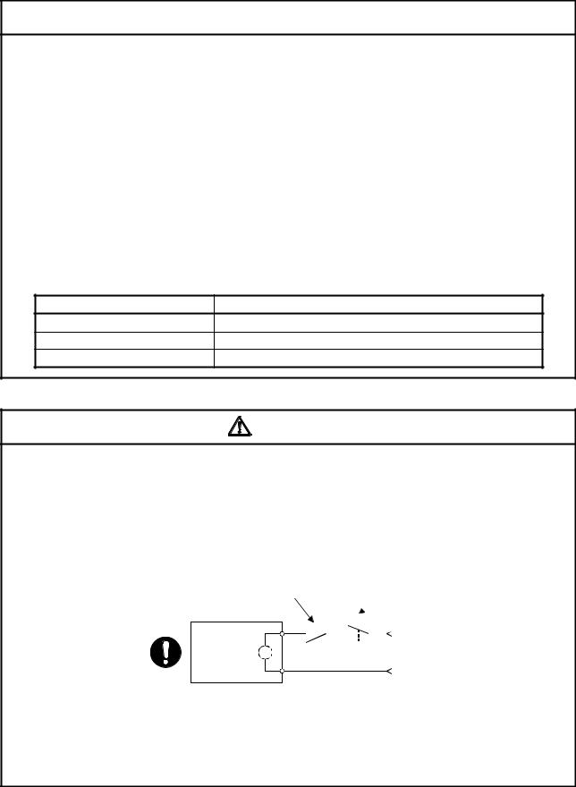
 Do not mistake the direction of the surge absorbing diode installed on the DC relay for the control signal output of brake signals, etc. Incorrect installation may lead to signals not being output when trouble occurs or the protective functions not functioning.
Servo amplifier |
24VDC |
Servo amplifier |
24VDC |
|
DOCOM |
DOCOM |
|||
|
|
|||
Control output |
RA |
Control output |
RA |
|
signal |
signal |
|||
DICOM |
|
DICOM |
|
|
For the sink output interface |
For the source output interface |
|||
 Do not connect or disconnect the connection cables between each unit or the encoder cable while the power is ON.
 Securely tighten the cable connector fixing screws and fixing mechanisms. Insufficient fixing may lead to the cables coming off during operation.
 Do not bundle the power line or cables.
(5) Trial operation and adjustment
 CAUTION
 Confirm and adjust the program and each parameter before operation. Unpredictable movements may occur depending on the machine.
 Extreme adjustments and changes may lead to unstable operation, so never make them.
 When using the absolute position system function, on starting up, and when the position board or absolute value motor has been replaced, always perform a home position return.
 Before starting test operation, set the parameter speed limit value to the slowest value, and make sure that operation can be stopped immediately by the forced stop, etc. if a hazardous state occurs.
A - 7
(6) Usage methods
 CAUTION
 Immediately turn OFF the power if smoke, abnormal sounds or odors are emitted from the position board, servo amplifier or servo motor.
 Always execute a test operation before starting actual operations after the program or parameters have been changed or after maintenance and inspection.
 Do not attempt to disassemble and repair the units excluding a qualified technician whom our company recognized.
 Do not make any modifications to the unit.
 Keep the effect or electromagnetic obstacles to a minimum by installing a noise filter or by using wire shields, etc. Electromagnetic obstacles may affect the electronic devices used near the position board or servo amplifier.
 When using the CE Mark-compliant equipment, refer to this manual for the position boards and refer to the corresponding EMC guideline information for the servo amplifiers, inverters and other equipment.
 Use the units with the following conditions.
Item |
Conditions |
Input power |
According to each instruction manual. |
Input frequency |
According to each instruction manual. |
Tolerable momentary power failure |
According to each instruction manual. |
(7) Corrective actions for errors |
|
|
CAUTION |
 If an error occurs in the self diagnosis of the position board or servo amplifier, confirm the check details according to the instruction manual, and restore the operation.
 If a dangerous state is predicted in case of a power failure or product failure, use a servo motor with electromagnetic brakes or install a brake mechanism externally.
 Use a double circuit construction so that the electromagnetic brake operation circuit can be operated by emergency stop signals set externally.
Shut off with servo ON signal OFF, alarm, electromagnetic brake signal.
Shut off with the emergency stop signal (EMG).
Servo motor |
|
|
EMG |
|||||
|
|
RA1 |
||||||
Electromagnetic |
B |
|
|
|
|
|
24VDC |
|
|
|
|
|
|
|
|||
|
|
|
|
|
|
|||
brakes |
|
|
|
|
|
|
|
|
 If an error occurs, remove the cause, secure the safety and then resume operation after alarm release.
 The unit may suddenly resume operation after a power failure is restored, so do not go near the machine. (Design the machine so that personal safety can be ensured even if the machine restarts suddenly.)
A - 8

(8) Maintenance, inspection and part replacement
 CAUTION
 Perform the daily and periodic inspections according to the instruction manual.
 Perform maintenance and inspection after backing up the program and parameters for the position board and servo amplifier.
 Do not place fingers or hands in the clearance when opening or closing any opening.
 Periodically replace consumable parts such as batteries according to the instruction manual.
 Do not touch the lead sections such as ICs or the connector contacts.
 Before touching the position board, always touch grounded metal, etc. to discharge static electricity from human body. Failure to do so may cause the position board to fail or malfunction.
 Do not directly touch the position board's conductive parts and electronic components. Touching them could cause an operation failure or give damage to the position board.
 Do not place the position board or servo amplifier on metal that may cause a power leakage or wood, plastic or vinyl that may cause static electricity buildup.
 Do not perform a megger test (insulation resistance measurement) during inspection.
 When replacing the position board or servo amplifier, always set the new position board settings correctly.
 When the position board or absolute value motor has been replaced, carry out a home position return operation from the user program. Failing to do so may cause position displacement.
 After maintenance and inspections are completed, confirm that the position detection of the absolute position detector function is correct.
 Do not drop or impact the battery installed to the module.
Doing so may damage the battery, causing battery liquid to leak in the battery. Do not use the dropped or impacted battery, but dispose of it.
 Do not short circuit, charge, overheat, incinerate or disassemble the batteries.
 The electrolytic capacitor will generate gas during a fault, so do not place your face near the position board or servo amplifier.
 The electrolytic capacitor and fan will deteriorate. Periodically replace these to prevent secondary damage from faults. Replacements can be made by our sales representative.
 Lock the control panel and prevent access to those who are not certified to handle or install electric equipment.
 Do not burn or break a position board and servo amplifier. Doing so may cause a toxic gas.
A - 9
(9) About processing of waste
When you discard position board, servo amplifier, a battery (primary battery) and other option articles, please follow the law of each country (area).
 CAUTION
 This product is not designed or manufactured to be used in equipment or systems in situations that can affect or endanger human life.
 When considering this product for operation in special applications such as machinery or systems used in passenger transportation, medical, aerospace, atomic power, electric power, or submarine repeating applications, please contact your nearest Mitsubishi sales representative.
  Although this product was manufactured under conditions of strict quality control, you are strongly advised to install safety devices to forestall serious accidents when it is used in facilities where a breakdown in the product is likely to cause a serious accident.
(10) General cautions
 All drawings provided in the instruction manual show the state with the covers and safety partitions removed to explain detailed sections. When operating the product, always return the covers and partitions to the designated positions, and operate according to the instruction manual.
A - 10

REVISIONS
 The manual number is given on the bottom left of the back cover.
Print Date |
Manual Number |
Revision |
Dec., 2013 IB(NA)-0300223-A First edition
Dec., 2014 IB(NA)-0300223-B [Additional model] MR-MC240, MR-MC241
[Additional function]
Speed-torque control, Mark detection, Continuous operation to torque control, External forced stop disabled
[Additional correction]
Alarm history, Home position return change while system is running, High speed monitor position droop, Table map, Log data (event code list, information for each event), Parameters (servo parameters, control parameters), Monitor number (operation information), Alarm number (system alarm, operation alarm), Supplementary explanation for the use of linear servo system, Supplementary explanation for the use of SSCNET compatible servo amplifier, Connector exterior dimensions
Japanese Manual Number IB(NA)-0300222
This manual confers no industrial property rights or any rights of any other kind, nor does it confer any patent licenses. Mitsubishi Electric Corporation cannot be held responsible for any problems involving industrial property rights which may occur as a result of using the contents noted in this manual.
© 2013 MITSUBISHI ELECTRIC CORPORATION
A - 11

INTRODUCTION
Thank you for choosing the Mitsubishi position board MR-MC210/MR-MC211/MR-MC240/MR-MC241. Before using the equipment, please read this manual carefully to develop full familiarity with the functions and performance of the position board you have purchased, so as to ensure correct use.
|
CONTENTS |
|
Safety Precautions ......................................................................................................................................... |
A- 1 |
|
Revisions ........................................................................................................................................................ |
A-11 |
|
Contents ......................................................................................................................................................... |
A-12 |
|
About Manuals................................................................................................................................................ |
A-21 |
|
|
|
|
1. SUMMARY |
1- 1 to 1-24 |
|
1.1 Summary ................................................................................................................................................... |
1- 1 |
|
1.2 |
Features..................................................................................................................................................... |
1- 6 |
1.3 |
Specifications ............................................................................................................................................ |
1- 9 |
1.3.1 General specifications........................................................................................................................ |
1- 9 |
|
1.3.2 List of specifications of position board.............................................................................................. |
1-10 |
|
1.4 |
Name of each section .............................................................................................................................. |
1-13 |
1.4.1 Name of parts for PCI bus compatible position board ..................................................................... |
1-13 |
|
1.4.2 Name of parts for PCI Express® bus compatible position board..................................................... |
1-15 |
|
1.5 |
Bus interface............................................................................................................................................. |
1-17 |
1.5.1 Configuration register........................................................................................................................ |
1-17 |
|
1.5.2 Dual port memory map...................................................................................................................... |
1-19 |
|
1.5.3 Module information............................................................................................................................ |
1-20 |
|
1.6 SSCNET cables .................................................................................................................................... |
1-22 |
|
1.7 |
Forced stop input terminal ....................................................................................................................... |
1-23 |
|
|
|
2. SYSTEM CONFIGURATION |
2- 1 to 2- 8 |
|
2.1 |
Position board configuration ..................................................................................................................... |
2- 1 |
2.1.1 MR-MC210 system configuration ...................................................................................................... |
2- 1 |
|
2.1.2 MR-MC211 system configuration ...................................................................................................... |
2- 2 |
|
2.1.3 MR-MC240 system configuration ...................................................................................................... |
2- 3 |
|
2.1.4 MR-MC241 system configuration ...................................................................................................... |
2- 4 |
|
2.2 |
System configuration equipment .............................................................................................................. |
2- 5 |
2.3 |
Checking serial number and operating system software version............................................................ |
2- 6 |
2.3.1 Checking serial number ..................................................................................................................... |
2- 6 |
|
2.3.2 Checking software version................................................................................................................. |
2- 6 |
|
2.4 |
Restrictions by the Software's Version..................................................................................................... |
2- 7 |
|
|
|
3. INSTALLATION AND WIRING |
3- 1 to 3- 6 |
|
3.1 |
Board installation....................................................................................................................................... |
3- 1 |
3.1.1 Instructions for handling ..................................................................................................................... |
3- 1 |
|
3.1.2 Installation environment ..................................................................................................................... |
3- 1 |
|
3.2 |
Connection and disconnection of cable.................................................................................................... |
3- 2 |
3.2.1 SSCNET cable ................................................................................................................................ |
3- 2 |
|
|
A - 12 |
|
3.2.2 Forced stop input cable...................................................................................................................... |
3- 6 |
|
|
|
|
4. SYSTEM STARTUP |
4- 1 to 4-18 |
|
4.1 |
Startup procedures.................................................................................................................................... |
4- 1 |
4.2 |
Check of wiring and ambient environment............................................................................................... |
4- 2 |
4.3 |
Position board setting................................................................................................................................ |
4- 3 |
4.4 |
Servo amplifier setting............................................................................................................................... |
4- 4 |
4.5 |
Parameter setting...................................................................................................................................... |
4- 6 |
4.5.1 Parameter initialization....................................................................................................................... |
4- 6 |
|
4.5.2 System option 1 setting...................................................................................................................... |
4- 7 |
|
4.5.3 System option 2 setting...................................................................................................................... |
4- 9 |
|
4.5.4 Control option 1 setting ..................................................................................................................... |
4-10 |
|
4.5.5 Axis No. assignment.......................................................................................................................... |
4-11 |
|
4.5.6 Sensor input option setting................................................................................................................ |
4-13 |
|
4.5.7 Vendor ID and type code setting ...................................................................................................... |
4-16 |
|
4.6 |
System startup processing ...................................................................................................................... |
4-17 |
|
|
|
5. OPERATIONAL FUNCTIONS |
5- 1 to 5-42 |
|
5.1 |
JOG operation ........................................................................................................................................... |
5- 2 |
5.1.1 Summary ............................................................................................................................................ |
5- 2 |
|
5.1.2 Start operation method....................................................................................................................... |
5- 2 |
|
5.1.3 Resuming operation ........................................................................................................................... |
5- 3 |
|
5.2 |
Incremental feed........................................................................................................................................ |
5- 4 |
5.2.1 Summary ............................................................................................................................................ |
5- 4 |
|
5.2.2 Start operation method....................................................................................................................... |
5- 5 |
|
5.3 |
Automatic operation .................................................................................................................................. |
5- 6 |
5.3.1 Summary ............................................................................................................................................ |
5- 6 |
|
5.3.2 Start operation method....................................................................................................................... |
5- 7 |
|
5.3.3 Auxiliary command............................................................................................................................. |
5- 8 |
|
5.3.4 Other axes start specification............................................................................................................ |
5-15 |
|
5.3.5 S-curve ratio ...................................................................................................................................... |
5-15 |
|
5.4 |
Linear interpolation................................................................................................................................... |
5-16 |
5.4.1 Summary ........................................................................................................................................... |
5-16 |
|
5.4.2 Settings.............................................................................................................................................. |
5-18 |
|
5.4.3 Start operation method...................................................................................................................... |
5-19 |
|
5.4.4 Processing for exceeding speed limit for each axis ......................................................................... |
5-20 |
|
5.4.5 Restrictions ........................................................................................................................................ |
5-21 |
|
5.5 |
Home position return................................................................................................................................ |
5-22 |
5.5.1 Summary ........................................................................................................................................... |
5-22 |
|
5.5.2 Home position return method ........................................................................................................... |
5-24 |
|
5.5.3 Start operation method...................................................................................................................... |
5-25 |
|
5.5.4 Home position return using a dog method ....................................................................................... |
5-27 |
|
5.5.5 Home position return using a data set method ................................................................................ |
5-29 |
|
5.5.6 Home position return using a stopper method ................................................................................. |
5-29 |
|
5.5.7 Home position return using a dog cradle method ............................................................................ |
5-30 |
|
5.5.8 Home position return using a limit switch combined method........................................................... |
5-32 |
|
5.5.9 Home position return using a limit switch front end method ............................................................ |
5-32 |
|
5.5.10 Home position return using a dog front end method...................................................................... |
5-33 |
|
|
A - 13 |
|
5.5.11 Home position return using a Z-phase detection method.............................................................. |
5-35 |
||
5.5.12 Home position return using a scale home position signal detection method................................ |
5-38 |
||
5.5.13 Home position return using a scale home position signal detection method 2............................. |
5-39 |
||
5.6 |
Home position reset function (data set function)..................................................................................... |
5-40 |
|
|
|
||
6. APPLICATION FUNCTIONS |
6- 1 to 6-146 |
||
6.1 |
Command units ......................................................................................................................................... |
6- 1 |
|
6.1.1 Position command unit - electronic gear ........................................................................................... |
6- 1 |
||
6.1.2 Settings............................................................................................................................................... |
6- 3 |
||
6.1.3 Setting example of electronic gears .................................................................................................. |
6- 3 |
||
6.1.4 Restrictions ......................................................................................................................................... |
6- 4 |
||
6.2 |
Speed unit ................................................................................................................................................. |
6- 5 |
|
6.2.1 Settings............................................................................................................................................... |
6- 5 |
||
6.2.2 Setting example of speed units.......................................................................................................... |
6- 6 |
||
6.2.3 Speed limit.......................................................................................................................................... |
6- 6 |
||
6.3 |
Acceleration/deceleration.......................................................................................................................... |
6- 7 |
|
6.3.1 Linear acceleration/deceleration........................................................................................................ |
6- 7 |
||
6.3.2 Smoothing filter................................................................................................................................... |
6- 8 |
||
6.3.3 Start up speed validity........................................................................................................................ |
6- 8 |
||
6.3.4 S-curve acceleration/deceleration (Sine acceleration/deceleration) ................................................ |
6- 9 |
||
6.4 |
Servo off ................................................................................................................................................... |
6-13 |
|
6.5 |
Forced stop............................................................................................................................................... |
6-14 |
|
6.6 |
Stop operation .......................................................................................................................................... |
6-15 |
|
6.7 |
Rapid stop operation................................................................................................................................ |
6-16 |
|
6.8 |
Limit switch (stroke end) .......................................................................................................................... |
6-17 |
|
6.9 |
Software limit............................................................................................................................................ |
6-18 |
|
6.10 |
Interlock .................................................................................................................................................. |
6-20 |
|
6.11 |
Rough match output............................................................................................................................... |
6-22 |
|
6.12 |
Torque limit............................................................................................................................................. |
6-23 |
|
6.13 Command change.................................................................................................................................. |
6-24 |
||
6.13.1 Speed change ................................................................................................................................. |
6-24 |
||
6.13.2 Change of time constants ............................................................................................................... |
6-25 |
||
6.13.3 Position change............................................................................................................................... |
6-26 |
||
6.14 |
Backlash ................................................................................................................................................. |
6-32 |
|
6.15 |
Position switch........................................................................................................................................ |
6-33 |
|
6.16 |
Completion of operation signal .............................................................................................................. |
6-34 |
|
6.17 |
Interference check function.................................................................................................................... |
6-40 |
|
6.17.1 Interface........................................................................................................................................... |
6-42 |
||
6.17.2 Interference check operation image diagram................................................................................. |
6-43 |
||
6.17.3 Checks prior to start up ................................................................................................................... |
6-44 |
||
6.17.4 Operation check .............................................................................................................................. |
6-45 |
||
6.18 |
Home position search limit..................................................................................................................... |
6-48 |
|
6.18.1 Summary ......................................................................................................................................... |
6-48 |
||
6.18.2 Set items.......................................................................................................................................... |
6-48 |
||
6.18.3 Home position search limit operation example .............................................................................. |
6-49 |
||
6.19 |
Gain changing ........................................................................................................................................ |
6-50 |
|
6.20 |
PI-PID switching..................................................................................................................................... |
6-52 |
|
6.21 |
Absolute position detection system ....................................................................................................... |
6-53 |
|
6.21.1 Parameters ...................................................................................................................................... |
6-53 |
||
|
|
A - 14 |
|
6.21.2 Processing procedure ..................................................................................................................... |
6-54 |
6.21.3 Sequence example ......................................................................................................................... |
6-56 |
6.22 Home position return request ................................................................................................................ |
6-58 |
6.23 Other axes start...................................................................................................................................... |
6-60 |
6.23.1 Summary ......................................................................................................................................... |
6-60 |
6.23.2 Settings............................................................................................................................................ |
6-60 |
6.23.3 Interface........................................................................................................................................... |
6-66 |
6.23.4 Operation example.......................................................................................................................... |
6-69 |
6.24 High response I/F................................................................................................................................... |
6-73 |
6.24.1 Summary ......................................................................................................................................... |
6-73 |
6.24.2 Interface........................................................................................................................................... |
6-74 |
6.24.3 Fast start operation ......................................................................................................................... |
6-75 |
6.24.4 Interrupt processing high speed completion .................................................................................. |
6-76 |
6.25 In-position signal .................................................................................................................................... |
6-77 |
6.26 Digital input/output ................................................................................................................................. |
6-78 |
6.26.1 Summary ......................................................................................................................................... |
6-78 |
6.26.2 Interface........................................................................................................................................... |
6-79 |
6.27 Servo amplifier general input/output...................................................................................................... |
6-80 |
6.27.1 Summary ......................................................................................................................................... |
6-80 |
6.27.2 Settings............................................................................................................................................ |
6-82 |
6.28 Dual port memory exclusive control ...................................................................................................... |
6-85 |
6.28.1 Summary ......................................................................................................................................... |
6-85 |
6.28.2 Exclusive control of digital output ................................................................................................... |
6-85 |
6.29 Pass position interrupt............................................................................................................................ |
6-87 |
6.29.1 Summary ......................................................................................................................................... |
6-87 |
6.29.2 Pass position interrupt setting method ........................................................................................... |
6-88 |
6.29.3 Interface........................................................................................................................................... |
6-89 |
6.29.4 Operation example........................................................................................................................ |
6-100 |
6.30 Mark detection...................................................................................................................................... |
6-104 |
6.30.1 Summary ....................................................................................................................................... |
6-104 |
6.30.2 Interface......................................................................................................................................... |
6-108 |
6.30.3 Function details ............................................................................................................................. |
6-116 |
6.30.4 Operation example........................................................................................................................ |
6-118 |
6.31 Continuous operation to torque control ............................................................................................... |
6-121 |
6.31.1 Summary ....................................................................................................................................... |
6-121 |
6.31.2 Interface......................................................................................................................................... |
6-123 |
6.31.3 Control mode switch...................................................................................................................... |
6-134 |
6.31.4 Operation timing ............................................................................................................................ |
6-136 |
6.31.5 Operation during continuous operation to torque control mode .................................................. |
6-140 |
6.31.6 Stop factors during continuous operation to torque control ......................................................... |
6-141 |
6.31.7 Combinations of continuous operation to torque control and other functions............................. |
6-143 |
6.31.8 Restrictions on servo amplifier functions.............................................................................. |
........6-145 |
|
|
7. AUXILIARY FUNCTION |
7- 1 to 7-108 |
7.1 Reading/writing parameters...................................................................................................................... |
7- 1 |
7.1.1 Writing parameters ............................................................................................................................. |
7- 1 |
7.1.2 Reading parameters........................................................................................................................... |
7- 3 |
7.2 Changing parameters at the servo ........................................................................................................... |
7- 4 |
7.3 Alarm and system error............................................................................................................................. |
7- 6 |
A - 15 |
|
7.4 Monitor function......................................................................................................................................... |
7- 8 |
7.4.1 Summary ............................................................................................................................................ |
7- 8 |
7.4.2 Monitor latch function ........................................................................................................................ |
7-10 |
7.5 High speed monitor function .................................................................................................................... |
7-11 |
7.5.1 Summary ........................................................................................................................................... |
7-11 |
7.5.2 Monitor latch function ........................................................................................................................ |
7-12 |
7.6 Interrupt .................................................................................................................................................... |
7-13 |
7.6.1 Interrupt sequence ............................................................................................................................ |
7-13 |
7.6.2 Interrupt conditions............................................................................................................................ |
7-15 |
7.6.3 Factor of interrupt .............................................................................................................................. |
7-16 |
7.6.4 Interrupt processing example............................................................................................................ |
7-24 |
7.7 User watchdog function ........................................................................................................................... |
7-25 |
7.8 Software reboot function .......................................................................................................................... |
7-26 |
7.9 Parameter backup.................................................................................................................................... |
7-27 |
7.10 Test mode............................................................................................................................................... |
7-31 |
7.10.1 Structural diagram ........................................................................................................................... |
7-31 |
7.10.2 Test operation mode ....................................................................................................................... |
7-32 |
7.11 Reconnect/disconnect function.............................................................................................................. |
7-33 |
7.11.1 Disconnection function summary.................................................................................................... |
7-33 |
7.11.2 Reconnect function summary ......................................................................................................... |
7-34 |
7.11.3 Interface........................................................................................................................................... |
7-35 |
7.11.4 Disconnection method..................................................................................................................... |
7-36 |
7.11.5 Reconnection method ..................................................................................................................... |
7-37 |
7.11.6 Restrictions...................................................................................................................................... |
7-38 |
7.12 Sampling................................................................................................................................................. |
7-39 |
7.12.1 Summary ......................................................................................................................................... |
7-39 |
7.12.2 Command/status bit ........................................................................................................................ |
7-40 |
7.12.3 Command/status data..................................................................................................................... |
7-43 |
7.12.4 Sampling setting write/read............................................................................................................. |
7-46 |
7.12.5 Details for sampling function settings ............................................................................................. |
7-47 |
7.12.6 Number of sampled points.............................................................................................................. |
7-53 |
7.12.7 Sampling items................................................................................................................................ |
7-54 |
7.12.8 Sampling trigger .............................................................................................................................. |
7-60 |
7.12.9 Sampling data read ......................................................................................................................... |
7-63 |
7.12.10 Timing chart for sampling function................................................................................................ |
7-65 |
7.13 Log.......................................................................................................................................................... |
7-74 |
7.13.1 Summary ......................................................................................................................................... |
7-74 |
7.13.2 Log data details ............................................................................................................................... |
7-75 |
7.13.3 Event code list ................................................................................................................................. |
7-76 |
7.13.4 Information for each event .............................................................................................................. |
7-78 |
7.13.5 Log function interface...................................................................................................................... |
7-87 |
7.13.6 Timing chart for reading of log data................................................................................................ |
7-90 |
7.13.7 Log acquiring selection ................................................................................................................... |
7-90 |
7.14 Operation cycle monitor function ........................................................................................................... |
7-91 |
7.14.1 Summary ................................................................................................................ |
.........................7-91 |
7.14.2 Interface........................................................................................................................................... |
7-91 |
7.14.3 Operation timing .............................................................................................................................. |
7-92 |
7.15 External forced stop disabled ................................................................................................................ |
7-94 |
7.15.1 Summary ......................................................................................................................................... |
7-94 |
7.15.2 Interface........................................................................................................................................... |
7-94 |
|
A - 16 |
7.15.3 Setting method ................................................................................................................................ |
7-94 |
|
7.16 Amplifier-less axis function .................................................................................................................... |
7-95 |
|
7.16.1 Summary ......................................................................................................................................... |
7-95 |
|
7.16.2 Interface........................................................................................................................................... |
7-95 |
|
7.16.3 Control details.................................................................................................................................. |
7-96 |
|
7.17 Alarm history function............................................................................................................................. |
7-97 |
|
7.17.1 Summary ......................................................................................................................................... |
7-97 |
|
7.17.2 Alarm history data details................................................................................................................ |
7-98 |
|
7.17.3 Interface......................................................................................................................................... |
7-103 |
|
7.17.4 Timing chart for alarm history read............................................................................................... |
7-106 |
|
7.17.5 Alarm history initialization procedure............................................................................................ |
7-107 |
|
7.17.6 List of system errors that do not apply to alarm history storage.................................................. |
7-107 |
|
|
|
|
8. TANDEM DRIVE |
8- 1 to 8-32 |
|
8.1 |
Drive modes .............................................................................................................................................. |
8- 1 |
8.1.1 Synchronous mode ............................................................................................................................ |
8- 2 |
|
8.1.2 Non-synchronous micro-adjustment control mode ........................................................................... |
8- 2 |
|
8.1.3 Changing of drive mode..................................................................................................................... |
8- 3 |
|
8.2 |
Parameter settings .................................................................................................................................... |
8- 4 |
8.2.1 Designation of tandem drive axes ..................................................................................................... |
8- 4 |
|
8.2.2 Servo parameters............................................................................................................................... |
8- 4 |
|
8.2.3 Control parameters............................................................................................................................. |
8- 4 |
|
8.3 |
Axis data classifications ............................................................................................................................ |
8- 5 |
8.3.1 Only data from master axis is valid.................................................................................................... |
8- 5 |
|
8.3.2 Individual data for master axis/slave axis.......................................................................................... |
8- 5 |
|
8.4 |
Tandem drive axis operation .................................................................................................................... |
8- 6 |
8.4.1 Home position return during tandem drive ........................................................................................ |
8- 6 |
|
8.4.2 JOG operation during tandem drive ................................................................................................. |
8-24 |
|
8.4.3 Incremental feed while using tandem drive...................................................................................... |
8-25 |
|
8.4.4 Automatic operation during tandem drive......................................................................................... |
8-26 |
|
8.4.5 Linear interpolation during tandem drive .......................................................................................... |
8-27 |
|
8.5 |
Servo on and servo off during tandem drive axis operation ................................................................... |
8-29 |
8.6 |
Tandem drive axis limit switch................................................................................................................. |
8-30 |
8.7 |
Tandem drive axis software limit ............................................................................................................. |
8-31 |
8.8 |
Tandem drive interference check ............................................................................................................ |
8-31 |
8.9 |
Tandem drive axis servo alarms.............................................................................................................. |
8-32 |
8.10 Deviation monitoring function ................................................................................................................ |
8-32 |
|
|
|
|
9. INTERFACE MODE |
9- 1 to 9-40 |
|
9.1 Summary ................................................................................................................................................... |
9- 1 |
|
9.2 |
Combinations with functions ..................................................................................................................... |
9- 2 |
9.3 |
Parameters ................................................................................................................................................ |
9- 4 |
9.4 |
Interface..................................................................................................................................................... |
9- 6 |
9.5 |
Control method......................................................................................................................................... |
9-11 |
9.5.1 Control mode ..................................................................................................................................... |
9-11 |
|
9.5.2 Position control mode........................................................................................................................ |
9-12 |
|
9.5.3 Speed control mode .......................................................................................................................... |
9-14 |
|
9.5.4 Torque control mode ......................................................................................................................... |
9-16 |
|
|
A - 17 |
|

9.5.5 Control method for interrupt output invalid ....................................................................................... |
9-18 |
|
9.5.6 Control method for interrupt output valid .......................................................................................... |
9-21 |
|
9.5.7 Procedure for switching control mode .............................................................................................. |
9-26 |
|
9.5.8 Examples of switching control mode ................................................................................................ |
9-28 |
|
9.6 Interrupt output cycle................................................................................................................................ |
9-31 |
|
9.7 Command data update cycle................................................................................................................... |
9-32 |
|
9.8 Servo off ................................................................................................................................................... |
9-33 |
|
9.9 Home position return................................................................................................................................ |
9-34 |
|
9.10 |
Coordinate management ....................................................................................................................... |
9-36 |
9.10.1 Incremental system ......................................................................................................................... |
9-36 |
|
9.10.2 Absolute position system ................................................................................................................ |
9-38 |
|
9.11 |
Precautions............................................................................................................................................. |
9-40 |
|
|
|
10. TABLE MAP |
10- 1 to 10-52 |
|
10.1 |
Table list ................................................................................................................................................ |
10- 1 |
10.2 |
System information ............................................................................................................................... |
10- 3 |
10.3 |
System command/status table ............................................................................................................. |
10- 5 |
10.4 |
Factor of interrupt................................................................................................................................. |
10-17 |
10.5 |
System configuration information table ............................................................................................... |
10-25 |
10.6 |
Axis data............................................................................................................................................... |
10-26 |
10.6.1 Axis data command table.............................................................................................................. |
10-26 |
|
10.6.2 Axis data status table .................................................................................................................... |
10-33 |
|
10.7 |
Servo parameter change number........................................................................................................ |
10-41 |
10.8 |
Point number offset.............................................................................................................................. |
10-45 |
10.9 |
Command buffers................................................................................................................................. |
10-46 |
10.10 Digital input/output table .................................................................................................................... |
10-48 |
|
10.11 Mark detection command/status table .............................................................................................. |
10-49 |
|
10.12 Mark detection data tables................................................................................................................. |
10-50 |
|
10.13 Continuous operation to torque control data table............................................................................ |
10-51 |
|
|
|
|
11. PARAMETERS |
11- 1 to 11-36 |
|
11.1 |
System parameters............................................................................................................................... |
11- 2 |
11.2 |
Servo parameters.................................................................................................................................. |
11- 4 |
11.2.1 Servo amplifier MR-J4(W )- B .................................................................................................... |
11- 4 |
|
11.3 |
Control parameters .............................................................................................................................. |
11-22 |
|
|
|
12. MONITOR NUMBER |
12- 1 to 12-20 |
|
12.1 |
Servo information (1)............................................................................................................................. |
12- 1 |
12.2 |
Servo information (2)............................................................................................................................. |
12- 3 |
12.3 |
Operation information ........................................................................................................................... |
12- 8 |
12.4 |
Operation information (double word)................................................................................................... |
12-11 |
12.5 |
System information .............................................................................................................................. |
12-12 |
12.6 |
Servo parameter information ............................................................................................................... |
12-14 |
|
|
|
13. ALARM NUMBER |
13- 1 to 13-12 |
|
13.1 |
System alarm ........................................................................................................................................ |
13- 1 |
13.2 |
Servo alarm ........................................................................................................................................... |
13- 2 |
13.3 |
Operation alarm..................................................................................................................................... |
13- 4 |
13.4 |
System error......................................................................................................................................... |
13-11 |
|
A - 18 |
|
14. EMC AND LOW VOLTAGE DIRECTIVES |
14- 1 to 14- 6 |
||
14.1 Requirements for compliance with the EMC directive ......................................................................... |
|
14- 1 |
|
14.1.1 Standards relevant to the EMC directive....................................................................................... |
|
14- 2 |
|
14.1.2 Installation instructions for EMC directive ..................................................................................... |
|
14- 3 |
|
14.1.3 Parts of measure against noise ..................................................................................................... |
|
14- 5 |
|
14.2 Requirements for compliance with the low voltage directive............................................................... |
|
14- 6 |
|
APPENDIX |
App.- 1 to App.-82 |
||
App. 1 Supplementary explanation for the use of linear servo system .................................................. |
|
App.- |
1 |
App. 1.1 Position board ........................................................................................................................ |
|
App.- |
1 |
App. 1.2 Position board utility software................................................................................................ |
|
App.- |
1 |
App. 1.3 Servo amplifier ....................................................................................................................... |
|
App.- |
1 |
App. 1.4 Operations and functions of the linear servo system ........................................................... |
|
App.- |
2 |
App. 2 Supplementary explanation for the use of fully closed loop system........................................... |
|
App.-13 |
|
App. 2.1 Position board ........................................................................................................................ |
|
App.-13 |
|
App. 2.2 Position board utility software................................................................................................ |
|
App.-13 |
|
App. 2.3 Servo amplifier ....................................................................................................................... |
|
App.-13 |
|
App. 2.4 Operations and functions of the fully closed loop control..................................................... |
|
App.-14 |
|
App. 3 Supplementary explanation for the use of direct drive servo system ......................................... |
|
App.-21 |
|
App. 3.1 Position board ........................................................................................................................ |
|
App.-21 |
|
App. 3.2 Position board utility software................................................................................................ |
|
App.-21 |
|
App. 3.3 Servo amplifier ....................................................................................................................... |
|
App.-21 |
|
App. 3.4 Operations and functions of the direct drive servo system .................................................. |
|
App.-22 |
|
App. 4 Supplementary explanation for the use of multiple-axis servo amplifier (MR-J4W |
- B) ....... |
App.-28 |
|
App. 4.1 Position board ........................................................................................................................ |
|
App.-28 |
|
App. 4.2 Position board utility software................................................................................................ |
|
App.-28 |
|
App. 4.3 Servo amplifier ....................................................................................................................... |
|
App.-28 |
|
App. 4.4 Operations and functions of the servo amplifier ................................................................... |
|
App.-28 |
|
App. 5 Supplementary explanation for the use of SSCNET compatible servo amplifier |
|
|
|
(MR-J3(W)- B) ........................................................................................................................... |
|
App.-30 |
|
App. 5.1 Position board ........................................................................................................................ |
|
App.-30 |
|
App. 5.2 Position board utility software................................................................................................ |
|
App.-30 |
|
App. 5.3 Connectable units .................................................................................................................. |
|
App.-30 |
|
App. 5.4 System setting ....................................................................................................................... |
|
App.-31 |
|
App. 5.5 System configuration ............................................................................................................. |
|
App.-31 |
|
App. 5.5.1 System configuration diagram ....................................................................................... |
|
App.-31 |
|
App. 5.6 Axis No. setting ...................................................................................................................... |
|
App.-32 |
|
App. 5.6.1 Servo amplifier setting.................................................................................................... |
|
App.-32 |
|
App. 5.7 Parameter setting .................................................................................................................. |
|
App.-33 |
|
App. 5.7.1 System option 1 setting.................................................................................................. |
|
App.-33 |
|
App. 5.8 Control option 1 setting.......................................................................................................... |
|
App.-35 |
|
App. 5.9 Axis No. assignment.............................................................................................................. |
|
App.-36 |
|
App. 5.10 Sensor input option setting.................................................................................................. |
|
App.-38 |
|
App. 5.11 Vendor ID and type code setting......................................................................................... |
|
App.-41 |
|
App. 5.12 System startup processing .................................................................................................. |
|
App.-41 |
|
App. 5.13 Restrictions when using J3 compatibility mode.................................................................. |
|
App.-42 |
|
App. 5.14 Supported functions............................................................................................................. |
|
App.-44 |
|
App. 5.14.1 Application functions .................................................................................................... |
|
App.-46 |
|
A - 19 |
|
|
|
App. 5.14.2 Auxiliary function .......................................................................................................... |
App.-50 |
|
App. 5.15 Table map ............................................................................................................................ |
App.-51 |
|
App. 5.15.1 Table list ....................................................................................................................... |
App.-52 |
|
App. 5.15.2 System information ...................................................................................................... |
App.-53 |
|
App. 5.15.3 Servo parameter change number................................................................................ |
App.-54 |
|
App. 5.16 Parameters .......................................................................................................................... |
App.-55 |
|
App. 5.16.1 System parameters...................................................................................................... |
App.-55 |
|
App. 5.16.2 Servo parameters......................................................................................................... |
App.-56 |
|
App. 5.16.3 Control parameters ...................................................................................................... |
App.-63 |
|
App. 5.17 Monitor ................................................................................................................................. |
|
App.-64 |
App. 5.17.1 Servo information (1).................................................................................................... |
App.-64 |
|
App. 5.17.2 Servo information (2).................................................................................................... |
App.-66 |
|
App. 5.17.3 Servo parameter information ....................................................................................... |
App.-71 |
|
App. 5.18 System alarm ....................................................................................................................... |
App.-73 |
|
App. 5.18.1 Servo alarm .................................................................................................................. |
App.-73 |
|
App. 6 Cables ........................................................................................................................................... |
|
App.-74 |
App. 6.1 SSCNET |
cables .................................................................................................................. |
App.-74 |
App. 6.2 Forced stop input cable ......................................................................................................... |
App.-77 |
|
App. 6.3 SSCNET |
cables (SC-J3BUS M-C) manufactured by Mitsubishi Electric System & |
|
Service.................................................................................................................................... |
|
App.-78 |
App. 7 Exterior dimensions ...................................................................................................................... |
App.-79 |
|
App. 7.1 PCI bus compatible position board ....................................................................................... |
App.-79 |
|
App. 7.2 PCI Express® bus compatible position board....................................................................... |
App.-80 |
|
App. 7.3 Connector............................................................................................................................... |
|
App.-81 |
A - 20

About Manuals
The following manuals are also related to this product.
In necessary, order them by quoting the details in the tables below.
Related Manuals
(1) Position Board
Manual Name |
Manual Number |
|
(Model Code) |
||
|
||
MR-MC210/MR-MC211/MR-MC240/MR-MC241 Position Board User's Manual (Details) |
|
|
This manual explains specifications of the position board, information on how to establish a system, |
IB-0300223 |
|
maintenance/inspection, trouble shooting, functions for the positioning control of the position board, |
(1XB968) |
|
programming, dual port memory and others. |
|
|
|
|
|
MR-MC210/MR-MC211/MR-MC240/MR-MC241 Position Board User's Manual (API Library) |
IB-0300225 |
|
This manual explains the library of functions and others that the host controller uses to control the position |
||
(1XB970) |
||
board. |
||
|
||
|
|
A - 21

(2) Servo amplifier
|
|
Manual Name |
|
Manual Number |
||
|
|
|
(Model Code) |
|||
|
|
|
|
|
||
SSCNET |
/H interface AC Servo MR-J4_B(-RJ)/MR-J4_B4(-RJ)/MR-J4_B1(-RJ) Servo |
|
||||
amplifier Instruction Manual |
|
|
SH-030106 |
|||
This manual explains the I/O signals, parts names, parameters, start-up procedure and others for AC |
(1CW805) |
|||||
Servo MR-J4_B(-RJ)/MR-J4_B4(-RJ)/MR-J4_B1(-RJ) Servo amplifier. |
|
|||||
|
|
|
||||
SSCNET |
/H interface Multi-axis AC Servo MR-J4W2-_B/MR-J4W3-_B Servo amplifier |
|
||||
Instruction Manual |
|
|
|
SH-030105 |
||
This manual explains the I/O signals, parts names, parameters, start-up procedure and others for Multi- |
(1CW806) |
|||||
axis AC Servo MR-J4W2-_B/MR-J4W3-_B Servo amplifier. |
|
|
||||
|
|
|
||||
SSCNET |
interface MR-J3- B Servo amplifier Instruction Manual |
SH-030051 |
||||
This manual explains the I/O signals, parts names, parameters, start-up procedure and others for |
||||||
(1CW202) |
||||||
MR-J3- |
B Servo amplifier. |
|
|
|
||
|
|
|
|
|||
|
|
|
|
|
||
SSCNET |
Compatible Linear Servo MR-J3- |
B-RJ004U |
Instruction Manual |
SH-030054 |
||
This manual explains the I/O signals, parts names, parameters, start-up procedure and others for Linear |
||||||
(1CW943) |
||||||
Servo MR-J3- B-RJ004U |
Servo amplifier. |
|
|
|||
|
|
|
||||
|
|
|
|
|||
SSCNET |
Compatible Fully Closed Loop Control MR-J3- |
B-RJ006 Servo amplifier |
|
|||
Instruction Manual |
|
|
|
SH-030056 |
||
This manual explains the I/O signals, parts names, parameters, start-up procedure and others for Fully |
(1CW304) |
|||||
Closed Loop Control MR-J3- |
B-RJ006 Servo amplifier. |
|
|
|||
|
|
|
||||
SSCNET |
interface 2-axis AC Servo AmplifierMR-J3W-0303BN6/MR-J3W- B Servo |
SH-030073 |
||||
amplifier Instruction Manual |
|
|
||||
This manual explains the I/O signals, parts names, parameters, start-up procedure and others for 2-axis |
(1CW604) |
|||||
AC Servo Amplifier MR-J3W-0303BN6/MR-J3W- |
B Servo amplifier. |
|
||||
SSCNET |
Interface Direct Drive Servo MR-J3- B-RJ080W Servo amplifier Instruction |
|
||||
Manual |
|
|
|
|
SH-030079 |
|
This manual explains the I/O signals, parts names, parameters, start-up procedure and others for Direct |
(1CW601) |
|||||
Drive Servo MR-J3- B-RJ080W Servo amplifier. |
|
|
|
|||
|
|
|
||||
SSCNET |
interface Drive Safety integrated MR-J3- B Safety Servo amplifier Instruction |
|
||||
Manual |
|
|
|
|
SH-030084 |
|
This manual explains the I/O signals, parts names, parameters, start-up procedure and others for safety |
(1CW205) |
|||||
integrated MR-J3- B Safety Servo amplifier. |
|
|
|
|||
|
|
|
|
|
|
|
A - 22
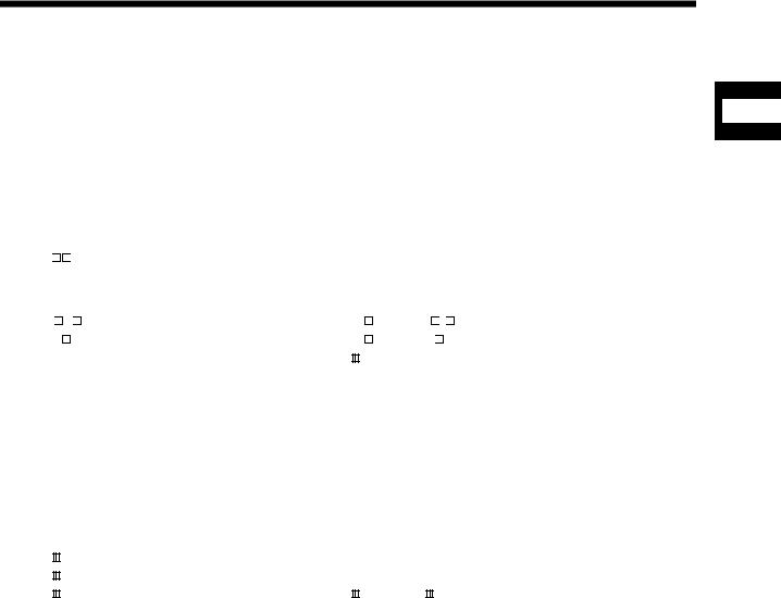
1.SUMMARY
1.SUMMARY
|
|
1.1 Summary |
1 |
This manual describes the specifications and handling of SSCNET /H compatible position board (MR-MC210/MR-MC211/MR-MC240/MR-MC241).
In this manual, the following abbreviations are used.
Generic term/Abbreviation |
|
Description |
|
||
MR-MC2 |
|
or position board |
General name for PCI bus compatible position board MR-MC210/MR-MC211/ |
||
|
PCI Express® bus compatible position board MR-MC240/MR-MC241 |
||||
|
|||||
Host controller |
General name for computer equipped with position board and operates user |
||||
program. |
|
|
|||
|
|
|
|
|
|
MR-J4(W )- B |
Servo amplifier model MR-J4- |
B/MR-J4W |
- B |
||
MR-J3(W)- B |
Servo amplifier model MR-J3- |
B/MR-J3W- |
B |
||
Servo amplifier |
General name for SSCNET /H compatible servo amplifier. |
||||
|
|
|
General name for the Position Board Utility2 (MRZJW3-MC2-UTL) which |
||
Utility software |
includes test tool for start-up and examination, and the API library for position |
||||
|
|
|
board. |
|
|
Test tool |
|
|
Abbreviation for start-up and examination tool for position board. |
||
API library |
|
|
General name for the library of functions for positioning control that the host |
||
|
|
controller uses to control the position board. |
|
||
|
|
|
|
||
MR Configurator2 |
Abbreviation for the Servo set-up software MR Configurator2 version 1.10L or |
||||
later. |
|
|
|||
|
|
|
|
|
|
User program |
Program created by the user that operates on the host controller. |
||||
System program |
Internal program that controls the position board. |
||||
SSCNET |
/H(Note) |
High-speed synchronized network between the position board and the servo |
|||
SSCNET |
(Note) |
amplifier. |
|
|
|
SSCNET |
(/H)(Note) |
General name for SSCNET /H, SSCNET . |
|
||
Board Ver. |
|
|
System version of position board. |
|
|
API Ver. |
|
|
Software version of the API library for position board. |
||
Note. SSCNET: Servo System Controller NETwork
1 - 1
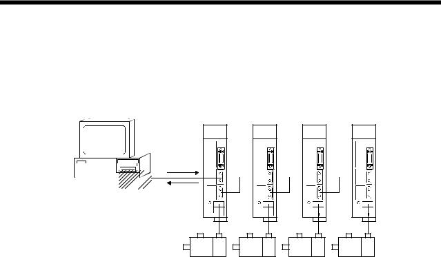
1. SUMMARY
(1)PCI bus compatible position board
The PCI bus compatible position board (MR-MC210/MR-MC211) is a board compatible with PCI bus mounted to the host controller and controls our servo amplifiers (MR-J4(W  )-
)- B/MR-J3(W)-
 B). The PCI bus compatible position board and the servo amplifiers are connected with SSCNET
 /H, which is a high speed synchronous network.
Host controller
Servo amplifier (MR-J4(W )-
)- B)
B)
Position instructions
parameters
 Position Position feedback board Speed
feedback
For the PCI bus compatible position board, there are two types, MR-MC210 and MR-MC211.
The MR-MC210 has one SSCNET control channel (hereinafter: CH) and one SSCNET line (hereinafter: line), and can control positioning for up to 20 axes. The MR-MC211 has one SSCNET control channel and two SSCNET lines, and can control positioning for up to 32 axes (up to 20 axes per line). By reading and writing the dual port memory mapped to the memory space of the PCI bus, the host controller can command position board to start operation, and get servo amplifier status. The host controller can also receive position pass and positioning complete interruptions via PCI bus.
The position board is equipped with standard mode and interface mode for positioning control. The positioning control mode that corresponds with the application can be selected by parameter. The mode cannot be changed during SSCNET communication (while system is running). Positioning in standard mode is performed using a point table mapped on the dual port memory of the position board. Arbitrary positioning is possible by writing data to this point table from the host controller.
Also, startup of JOG operation and home position return, etc. as well as parameters changing and monitoring are possible through accessing this dual port memory on the position board from the host controller.
Interface mode is a sequential positioning command method that uses a user program on the host controller. The user program controls the servo amplifier with an arbitrary acceleration/deceleration pattern by writing the position command to the position command buffer of the position board every communication cycle (control cycle). Some functions from standard mode cannot be used, or are restricted when in interface mode.
1 - 2
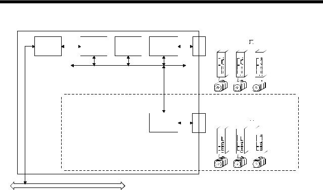
1. SUMMARY
Bus |
|
Dual port |
|
SSCNET |
|
CH1 |
|
SSCNET /H |
||
|
CPU |
Communi- |
|
|
|
|
|
|||
interface |
|
memory |
|
|
|
|
|
|
||
|
|
cation IC |
|
|
|
|
|
|
||
|
|
|
|
|
|
|
|
|
|
|
Local bus

 (Max 20 axes)
SSCNET |
|
CH2 |
|
SSCNET /H |
||
Communi- |
|
|
|
|
|
|
cation IC |
|
|
|
|
|
|
|
|
|
|
|
|
|

 (Max 12 axes)
PCI bus |
Inside the dotted line: only when using MR-MC211 |
|
1 - 3
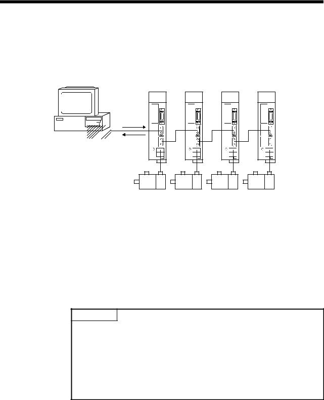
1. SUMMARY
(2)PCI Express® bus compatible position board
The PCI Express® bus compatible position board (MR-MC240/MR-MC241) is a board compatible with PCI Express® bus mounted to a PCI Express® system and controls our servo amplifiers (MR-J4(W )-
)- B/ MR-J3(W)-
 B). The PCI Express® bus compatible position board and the servo amplifiers are connected with SSCNET
 /H, which is a high speed synchronous network.
Host controller
Servo amplifier (MR-J4(W )-
)- B)
B)
Position instructions
parameters
 Position Position feedback board Speed
feedback
For the PCI Express® bus compatible position board, there are two types, MR-MC240 and MR-MC241. The MR-MC240 has one SSCNET control channel (hereinafter: CH) and one SSCNET communication line (hereinafter: line), and can control positioning for up to 20 axes. The MR-MC241 has one SSCNET control channel and two SSCNET communication lines, and can control positioning for up to 32 axes (up to 20 axes per communication line). Positioning is performed using a point table mapped on the dual port memory of the PCI Express® bus compatible position board. Arbitrary positioning is possible by writing data to this point table from the PCI bus compatible host controller.
Also, startup of JOG operation and home position return, etc. as well as parameter changing and monitoring are possible through accessing this dual port memory on the position board from the host controller. The dual port memory is mapped on the memory space of the PCI Express® bus.
POINT
•Depending on the specifications of the host controller, the PCI Express® slot
may be directly connected to the CPU of the host controller.
If the PCI Express® compatible position board is mounted to a PCI Express® slot that is directly connected to the CPU of the host controller, it may not be
able to operate.
Mount the PCI Express® compatible position board to a PCI Express® slot that is not directly connected to the CPU of the host controller (connected to a chipset).
1 - 4
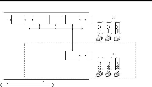
1. SUMMARY
Bus |
|
Dual port |
|
SSCNET |
|
CH1 |
|
SSCNET /H |
||
|
CPU |
Communi- |
|
|
|
|
|
|||
interface |
|
memory |
|
|
|
|
|
|
||
|
|
cation IC |
|
|
|
|
|
|
||
|
|
|
|
|
|
|
|
|
|
|
Local bus

 (Max 20 axes)
SSCNET |
|
CH2 |
|
SSCNET /H |
||
Communi- |
|
|
|
|
|
|
cation IC |
|
|
|
|
|
|
|
|
|
|
|
|
|

 (Max 12 axes)
PCI Express R bus |
Inside the dotted line: only when using MR-MC241 |
|
1 - 5

1. SUMMARY
1.2 Features
The position board has the following features.
(1)Structuring of SSCNET /H communication servo system by computer control
The position board can be directly connected to the Mitsubishi servo amplifiers of MR-J4-B series using SSCNET /H.
/H.
(a)By connecting the position board and servo amplifier and servo amplifiers with a high speed synchronous network by SSCNET /H, the reduction of wiring is achieved. The maximum distance between the position board and servo amplifier, or servo amplifier and servo amplifier for the SSCNET
 cable on the same bus is 100(328.08)[m(ft.)]. This increases flexibility at system design.
(b)By using SSCNET cable (optical communication), the influence of electromagnetic noise etc. from servo amplifiers and such is reduced.
(c)The servo parameters can be set on the position board side and written to the servo amplifier, or read from the servo amplifier using the SSCNET communication.
(d)The current feedback position and error description contained in the servo can be checked by the dual port memory of the position board.
(e)Communication between MR Configurator2 and the servo amplifiers is possible via the position board USB.
(2)Programming in C programming language with the API library
Positioning control for the servo in C programming language is enabled with the API library included with the Position Board Utility2 (MRZJW3-MC2-UTL).
(3)Supports event-driven programming
The host controller is notified by interrupt via PCI bus when the conditions for an interrupt such as passing through a preset point or positioning complete are met. The user program can create event-driven programs according to interrupt factors.
(4)High-speed operation starting time
High-speed operation starting time within the control cycle (0.22ms fastest) is achieved for the maximum number of synchronous startup axes or less.
1 - 6

1. SUMMARY
(5)Wide variety of positioning control functions
The main functions (such as home position return control, standard mode, and interface mode (sequential positioning command method)) which are required for any positioning system and the sub functions which limit and add functions to those controls are supported.
(a)Enhanced home position return control Additional features of home position return control
Ten home position return methods are provided: dog cradle method, dog method, data set method, continuous operation to torque method, limit switch combined method, scale home position signal detection method, limit switch front end method, dog front end method, Z-phase detection method, and scale home position signal detection method 2. Select an applicable method according to the system.
(b)Wide variety of control methods
Positioning control methods such as positioning control are provided.
1)Independent control of each axis
Position control can be performed independently for each axis at any given timing.
2)Interpolation control
Interpolation controls using multiple axes can be performed. (2-axis to 4-axis linear interpolation control)
3)Tandem drive
Tandem drive for 2 axes can be performed. In scale home position signal detection method and scale home position signal detection method 2, the deviation between the 2 axes at home position return can be compensated.
4)Interface mode
The user program controls the servo amplifier with an arbitrary acceleration/deceleration pattern that is not supported in standard mode by writing the position command to the position command buffer of the position board every communication cycle (control cycle).
(c)Continuous processing of multiple positioning data
Multiple positioning data can be processed continuously within one operation start.
(d)Acceleration/deceleration processing
Four acceleration/deceleration processing methods are provided: Linear acceleration/deceleration, S-curve acceleration/deceleration, start up speed, and smoothing filter.
The acceleration/deceleration curve can be selected according to the machine characteristic.
(6)Supports other axes start function
With the other axes start function, the position board can determine the conditions and automatically start other axes, and turn on/off output signals. The position board does not go through user program processing so there are no delays or dispersions. This also lessens the load on the user program.
(7)High maintainability
Maintainability is enhanced in the position board.
(a)Data retention without battery
Parameter data can be stored in the flash ROM inside the position board. This feature allows the retaining of data without a battery.
(b)Alarm collection function
The alarm details when an alarm occurs are automatically stored in the flash ROM inside the position board.
Storing the alarm information allows the user to check the alarm from the user program or test tool even after the position board is powered off or reset.
1 - 7
Loading...