


Mitsubishi MCF-C13UV-E1, MCF-C18UV-E1, MCF-C24UV-E1, MUCF-C13UV-E1, MUCF-C18UV-E1 Service Manual
...FLOOR AND CEILING TYPE AIR CONDITIONERS
HFC |
No. OB299 |
|
|
utilized |
|
R407C |
|
SERVICE MANUAL
Wireless type Models
MCF-C13UV- E1 (WH) ·MUCF-C13UVE1- MCF-C18UV- E1 (WH) ·MUCF-C18UVE1- MCF-C24UV- E1 (WH) ·MUCF-C24UVE1-
(When installed on the floor)
(When installed on the ceiling)
CONTENTS
1.TECHNICAL CHANGES ··················
2.PART NAMES AND FUNCTIONS··············
3.SPECIFICATION·····················
4.NOISE CRITERIA CURVES ················
5.OUTLINES AND DIMENSIONS ···············
6.WIRING DIAGRAM····················
7.REFRIGERANT SYSTEM DIAGRAM ············
8.PERFORMANCE CURVES ················
9.MICROPROCESSOR CONTROL ··············
10.SERVICE FUNCTIONS··················
11.TROUBLESHOOTING ···················
12.DISASSEMBLY INSTRUCTIONS··············
13.PARTS LIST·······················
14.OPTIONAL PARTS ····················

1 
 TECHNICAL CHANGES
INFORMATION FOR THE AIR CONDITIONER WITH R407C REFRIGERANT
This room air conditioner adopts HFC refrigerant (R407C) which never destroy the ozone layer. Pay attention to following points.
1Take sufficient care not to allow water and other contaminations to enter the R407C refrigerant during storage and installation, since it is more susceptible to contaminations than HCFC (R22) refrigerant.
2 Clean refrigerant piping should be used.
3Composition change may occur in R407C since it is a mixed refrigerant. When charging, charge liquid refrigerant to prevent composition change.
4Be especially careful when managing the tools.
If dust, dirt, or water mixes in the refrigerant cycle, it may cause decrease of performance.
|
|
New refrigerant |
Previous refrigerant |
|
Refrigerant |
R407C |
R22 |
|
Composition (Ratio) |
R32: R125: R134a (23%:25%:52%) |
HCFC22 (100%) |
|
Refrigerant handling |
Non-azeotropic refrigerant |
Single refrigerant |
|
Chlorine |
Not included |
Included |
Refrigerant |
Safety group (ASHRAE) |
A1/A1 |
A1 |
Saturated steam density [25:](Kg/K) |
42.5 |
44.4 |
|
|
Molecular weight |
86.2 |
86.5 |
|
Boiling point (:) |
-43.6 |
-40.8 |
|
Steam pressure [25:](Mpa [Gauge]) |
0.9177 |
0.94 |
|
|
|
|
|
Combustibility |
Non combustible |
Non combustible |
|
ODP w1 |
0 |
0.055 |
|
GWP w2 |
1530 |
1700 |
|
Refrigerant charge method |
From liquid phase in cylinder |
Gas phase |
|
Additional charge on leakage |
Impossible |
Possible |
Lubricant |
Kind |
Incompatible oil |
Compatible oil |
|
|||
|
Color |
Non |
Light yellow |
|
Smell |
Non |
Non |
w1 :Ozone Destruction Parameter |
|
: based on CFC11 |
|
|
|
|
|
|
|
||||||
w2 :Global Warmth Parameter |
|
: based on CO2 |
|
|
|
|
|
|
|
||||||
|
|
|
|
|
|
|
|
|
|
|
|
|
|
|
|
|
New Specification |
Previous Specification |
|||||||||||||
|
|
|
|
|
|
|
|
|
|
|
|
|
|
|
|
|
The incompatible lubricant easily separates from refrigerant |
Since refrigerant and lubricant are compatible each other, |
|||||||||||||
|
and makes the layer in the upper inside the suction muffler. |
lubricant returns to the compressor through the lower |
|||||||||||||
|
The higher position of the returning oil hole enables to return |
position returning oil hole. |
|||||||||||||
Compressor |
the lubricant of the upper layer to the compressor. |
Compressor |
|||||||||||||
Compressor |
|
|
|
Returning oil hole |
|||||||||||
|
|
|
|
|
|
|
Suction muffler |
|
|
|
|
|
|
Suction muffler |
|
|
|
|
|
|
|
|
|
Lubricant |
|
|
|
|
|
|
Returning oil hole |
|
|
|
|
|
|
|
|
|
|
|
|
|
|
||
|
|
|
|
|
|
|
|
|
|
|
|
|
|
||
|
|
|
|
|
|
|
|
||||||||
|
|
|
|
|
|
|
Refrigerant |
|
|
|
|
Lubricant and Refrigerant |
|||
|
|
|
|
|
|
|
|
|
|
|
|
|
|
|
|
Conversion chart of refrigerant temperature and pressure
(MPa[Gauge])
|
4.0 |
|
pressure |
3.5 |
R407C |
2.5 |
||
|
|
|
|
3.0 |
R22 |
liquid |
2.0 |
|
|
|
|
Saturated |
1.5 |
|
1.0 |
|
|
|
|
|
|
0.5 |
|
|
0.0 |
|
-0.5
-30 -20 -10 0 10 20 30 40 50 60 (:)
NOTE : The unit of pressure has been changed to MPa on the international system of units(SI unit system).
The conversion factor is: 1(MPa[Gauge]) =10.2(kgf/f[Gauge])
2
1.Tools dedicated for the air conditioner with R407C refrigerant
The following tools are required for R407C refrigerant. Some R22 tools can be substituted for R407C tools. Do not use tools that are used with R22 refrigerant in order to avoid mixing oils.
R407C tools |
Can R22 tools be used? |
|
Description |
||
Gauge manifold |
No |
A gauge manifold with a sight glass is recommended for charging the |
|||
liquid refregerant. |
|||||
|
|
||||
Charge hose |
No |
Hose material have been changed to improve the pressure |
|||
resistance. |
|||||
|
|
||||
Gas leak detector |
No |
Dedicated for HFC refrigerant. |
|||
|
|
|
|
|
|
Torque wrench |
Yes |
|
|
|
|
|
|
|
|||
|
|
|
|
|
|
Flare tool |
Yes |
|
|
|
|
|
|
|
|||
|
|
|
|
|
|
Vacuum pump |
New |
Provided to prevent the back flow of oil. This adapter enables you to use |
|||
adapter |
existing vacuum pumps. |
||||
|
|||||
Electronic scale for |
New |
Use the electronic control scale for measuring the R407C. |
|||
refrigerant charging |
|||||
|
|
|
|
||
|
|
|
|
|
|
2.Refrigerant piping
Do not use copper pipes which are broken, deformed or discoloured.
In addition, be sure that the inner surfaces of the pipes are clean, free of hazardous sulfur and oxides, or have no dust/ dirt, shaving particles, oil, moisture or any other contamination.
•If there is a large amount of residual oil inside the piping and joints, deterioration of the refrigerant oil will result.
3.Refrigerant oil
Apply the specific refrigeration oil (accessories) to the flare and the union seat surfaces.
4.Air purge
Use the vacuum pump for air purge to protect environments, and to avoid changing the composition of refrigerant.
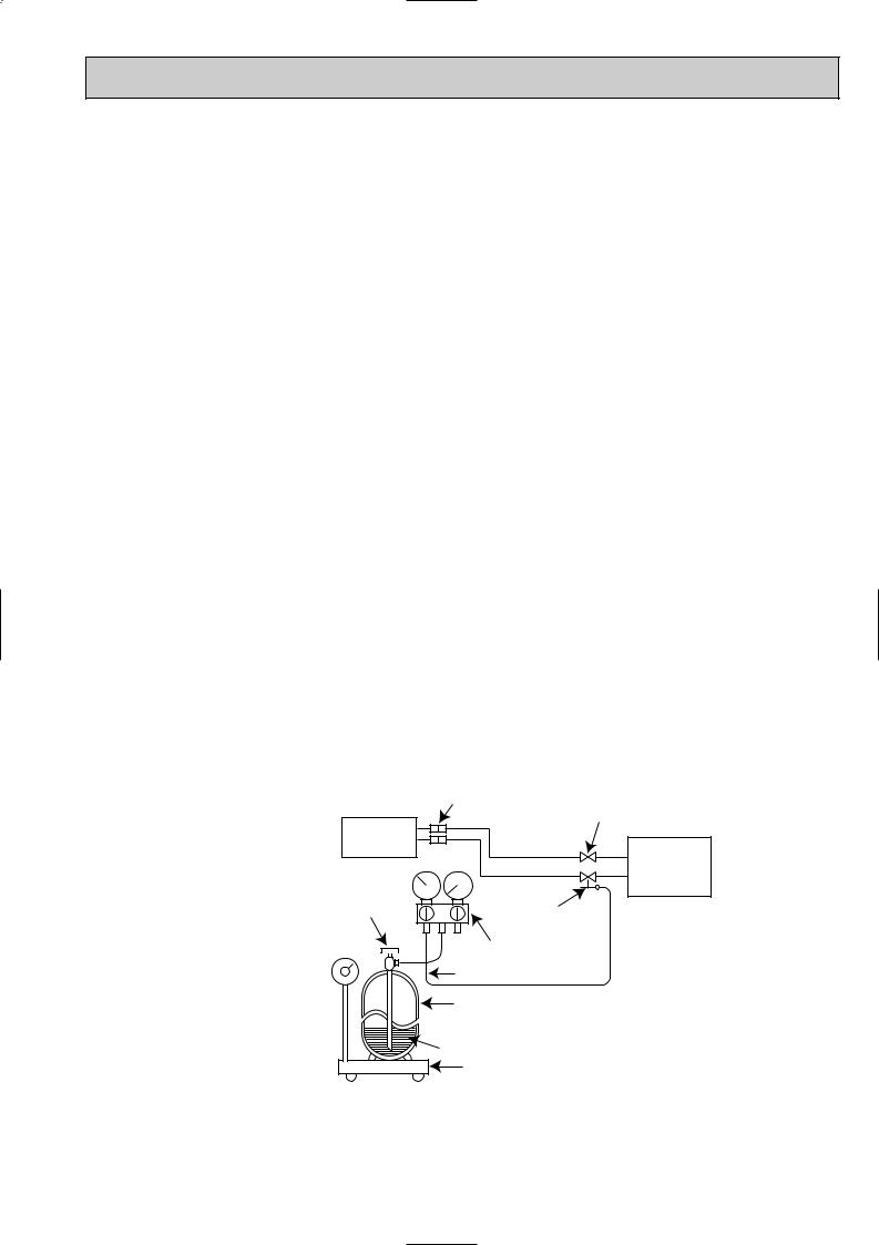
5.Additional charge
For additional charging, charge the refrigerant with liquid phase slowly using a gas cylinder. If the refrigerant is charged with gas phase, the composition of refrigerant will change. In this case, ability of the refrigerating cycle decreases or normal operation can be impossible.
If liquid refrigerant is rapidly charged at once, the compressor may be locked.
NOTE: 1. The R407C is mixed refrigerant which consist of three different kinds of evaporative temperature. As a result, the R407C occurs the change of composition.
2.Additional refrigerant charge has been changed by change of refrigerant.(R22 R407C) R22 : <MCF-type> 15g/m R407C : <MCF-C13UV> 15g/m, <MCF-C18/C24UV> 20g/m
|
Union |
|
|
|
Stop valve |
Indoor unit |
Liquid pipe |
|
|
|
|
Refrigerant |
Gas pipe |
Outdoor unit |
|
|
|
gas cylinder |
|
|
operating |
Service port |
|
valve |
|
|
|
|
|
|
Gage manifold |
|
|
Charge hose |
|
|
Refrigerant gas cylinder |
|
|
for R407C with siphon |
|
|
Refrigerant (liquid) |
|
|
Electronic scale for |
|
|
refrigerant charging |
|
3
2 
 PART NAMES AND FUNCTIONS
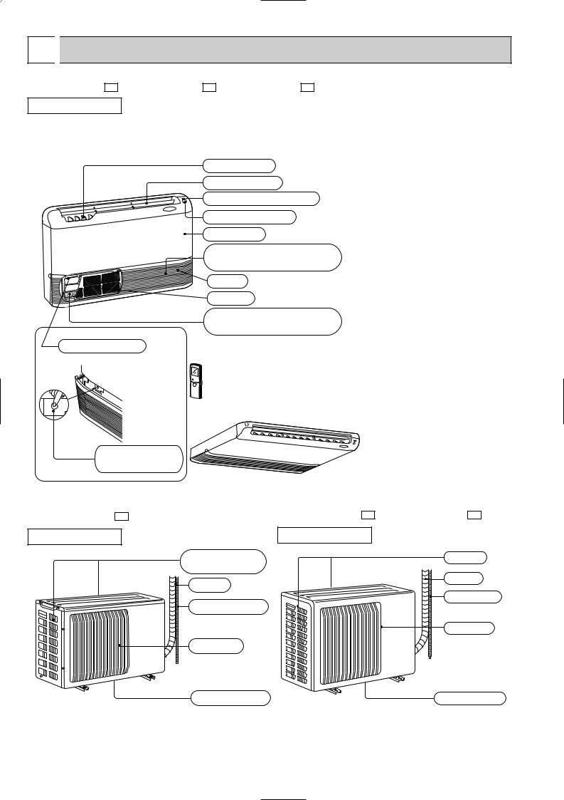
MCF-C13UV - E1 MCF-C18UV - E1 MCF-C24UV - E1
INDOOR UNIT
(When installed on the floor)
Vertical vanes
Horizontal vane
Operation indicator lamp
Receiving section
Front panel
Air cleaning filter
(white bellows type)(option)
Air inlet
Air filter
Deodorizing filter
(gray sponge type)(option)
Operation section
(When the air inlet grille is opened.)

 Remote controller
(When installed on the ceiling)
Emergency operation switch
ACCESSORIES
|
Item |
Q'ty |
1 |
Installation plate |
2 |
2 |
Unit fixing screw |
2 |
|
5 o 12mm |
|
3 |
Wireless remote |
1 |
|
controller |
|
4 |
Remote controller |
1 |
|
holder |
|
5 |
Fixing screw for 4 |
2 |
|
3.5 o 16mm (Black) |
|
6 |
Battery (AAA) for |
2 |
|
remote controller |
|
7 |
Drain hose |
1 |
8 |
Drain pipe cover |
1 |
9 |
Knockout cover |
1 |
0 |
Screw for 9 4 o 10mm |
2 |
1 |
Refrigerating oil |
1 |
MUCF-C13UV - E1 |
MUCF-C18UV - E1 MUCF-C24UV - E1 |
OUTDOOR UNIT |
OUTDOOR UNIT |
Air inlet |
Air inlet |
(back and side) |
|
Piping |
Piping |
|
|
|
Drain hose |
Drain hose |
|
|
Air outlet |
Air outlet |
|
Drain outlet |
Drain outlet |
4
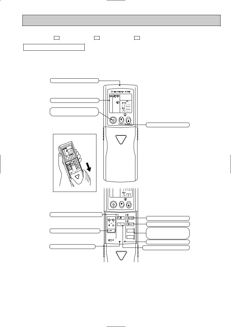
MCF-C13UV - E1 MCF-C18UV - E1 MCF-C24UV - E1
REMOTE CONTROLLER
Signal transmitting section
Operation display section
OPERATE /STOP (ON /OFF)button
|
|
PM |
|
|
AM |
ON/OFF |
TOO |
TOO |
|
WARM |
COOL |
TEMPERATURE buttons
Open the front lid. |
Open the front lid. |
CLOCK |
PM |
AM |
ON/OFF |
TOO |
TOO |
|
WARM |
COOL |
FAN SPEED CONTROL button |
FAN |
STOP |
|
I FEEL COOL |
|
|
VANE |
START |
|
FAN DRY |
|
OPERATION SELECT button |
MODE |
HR. |
|
MIN. |
|
|
|
|
|
RESET CLOCK |
|
RESET button |
|
|
OFF-TIMER button
ON-TIMER button
HR. button MIN. button (TIME SET button)
CLOCK SET button
VANE CONTROL button
5
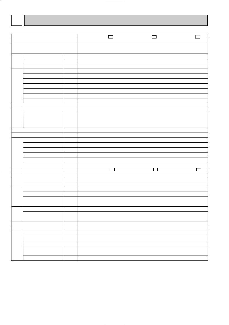
3 SPECIFICATION
Indoor model
Function
Power supply
Capacity |
Air flow(High/Med.W/LowW) |
K /h |
|
|
Capacity |
kW |
|
|
Dehumidification |
R/h |
|
|
Power outlet |
A |
|
|
Running current |
A |
|
Electrical data |
Power input |
W |
|
Auxiliary heater |
A(kW) |
||
|
|||
|
Power factor |
% |
|
|
Starting current |
A |
|
|
Fan motor current |
A |
|
Coefficient of performance(C.O.P) |
|||
Fan motor |
Model |
|
|
Winding |
|
||
|
|
||
|
resistance(at20:) |
" |
|
|
Dimensions WOHOD |
mm |
|
|
Weight |
kg |
|
|
Air direction |
|
|
Special remarks |
Sound level(High/Med.W/LowW) |
dB |
|
Fan speed(High/Med.W/LowW) |
rpm |
||
|
|||
|
Fan speed regulator |
|
|
|
Thermistor RT11(at25:) |
k" |
|
|
Thermistor RT12(at25:) |
k" |
|
|
Outdoor model |
|
|
Capacity Air flow(High/LowW) |
K /h |
||
Electrical data |
Fan motor current |
A |
|
|
Compressor motor current |
A |
|
Compressor |
Model |
|
|
Output |
W |
||
|
|||
|
Winding |
" |
|
|
resistance(at20:) |
||
|
|
||
Fan motor |
Model |
" |
|
Winding |
|||
|
|
||
|
resistance(at20:) |
|
|
|
Dimensions WOHOD |
mm |
|
|
Weight |
kg |
|
|
Sound level (High) |
dB |
|
Special remarks |
Fan speed(High/LowW) |
rpm |
|
Fan speed regulator |
|
||
|
|
||
|
Refrigerant filling |
kg |
|
|
capacity(R407C) |
||
|
|
||
|
Refrigerating oil (Model) |
cc |
|
MCF-C13UV - E1 |
|
MCF-C18UV - E1 |
|
MCF-C24UV - E1 |
||||||
Cooling |
|
Cooling |
|
Cooling |
||||||
Single phase |
|
Single phase |
|
Single phase |
||||||
230V, 50Hz |
|
230V, 50Hz |
|
230V, 50Hz |
||||||
3.55 |
|
5.0 |
|
6.4 |
||||||
1.5 |
|
2.3 |
|
3.6 |
||||||
678/582W/474W |
|
840/696W/570W |
|
840/744W/642W |
||||||
10 |
|
|
15 |
|
25 |
|||||
6.2 |
|
9.7 |
|
13.1 |
||||||
1,400 |
|
2,180 |
|
2,920 |
||||||
|
|
|
|
|
|
|
|
|
|
|
98 |
|
|
98 |
|
97 |
|||||
34 |
|
|
50 |
|
83 |
|||||
0.26 |
|
0.36 |
|
0.36 |
||||||
2.54 |
|
2.29 |
|
2.19 |
||||||
RB4V19-AB |
|
RB4V36-AB |
|
RB4V36-DA |
||||||
WHT-BLK 203.2 BLK-YLW 45.9 |
|
WHT-BLK 82.9 BLK-YLW 65.6 |
|
WHT-BLK 84.0 BLK-YLW 46.2 |
||||||
YLW-BLU 32.7 BLU-BRN 44.4 |
|
YLW-BLU 36.0 BLU-BRN 27.0 |
|
YLW-BLU 37.3 BLU-BRN 45.2 |
||||||
BRN-RED 23.3 |
|
BRN-RED 13.7 |
|
BRN-RED 13.6 |
||||||
|
|
|
|
1,100O650O180 |
|
|
|
|
||
|
|
|
26 |
|
|
|
|
|||
|
|
|
5 |
|
|
|
|
|
||
44/40W/34W |
|
48/44W/39W |
|
48/45W/42W |
||||||
|
|
|||||||||
1,105/970W/820W |
|
1,320/1,145W/960W |
|
1,320/1,190W/1,060W |
||||||
|
|
|
3 |
|
|
|
|
|
||
|
|
|
10 |
|
|
|
|
|||
|
|
|
10 |
|
|
|
|
|||
MUCF-C13UV - E1 |
|
MUCF-C18UV - E1 |
|
MUCF-C24UV - E1 |
||||||
|
|
|||||||||
High:1,914 |
|
High:2,238 |
|
2,322/1,638W |
||||||
5.57 |
|
8.95 |
|
12.19 |
||||||
0.37 |
|
0.39 |
|
0.55 |
||||||
RE231VHSHT |
|
PE33VPEHT |
|
NE47VMHHT |
||||||
1,100 |
|
1,500 |
|
2,200 |
||||||
C-R 2.25 |
|
C-R 1.08 |
|
C-R 0.67 |
||||||
C-S 4.07 |
|
C-S 2.18 |
|
C-S 2.02 |
||||||
RA6V33-CB |
|
RA6V50-OG |
|
RA6V60-AC |
||||||
WHT-BLK 176 |
|
WHT-BLK 116 |
|
WHT-BLK 81 BLK-YLW 92 |
||||||
BLK-RED 413 |
|
BLK-RED 111 |
|
BLK-RED 102 |
||||||
780o540o255 |
|
|
|
850o605o290 |
||||||
34 |
|
|
48 |
|
||||||
|
|
|
61 |
|||||||
49 |
|
|
52 |
|
53 |
|||||
High:725 |
|
High:828 |
|
873/629W |
||||||
1 |
|
|
1 |
|
|
2 |
|
|||
0.95 |
|
1.10 |
|
1.85 |
||||||
620 (NEO22) |
|
1,100 (NEO22) |
|
1,400 (NEO22) |
||||||
|
|
|
|
|
|
|
|
|
|
|
NOTE:Test conditions are based on ISO 5151
Cooling : Indoor DB27°C WB19°C
Outdoor DB35°C WB(24°C)
Indoor-Outdoor piping length 5 m
W Reference value
6

4 
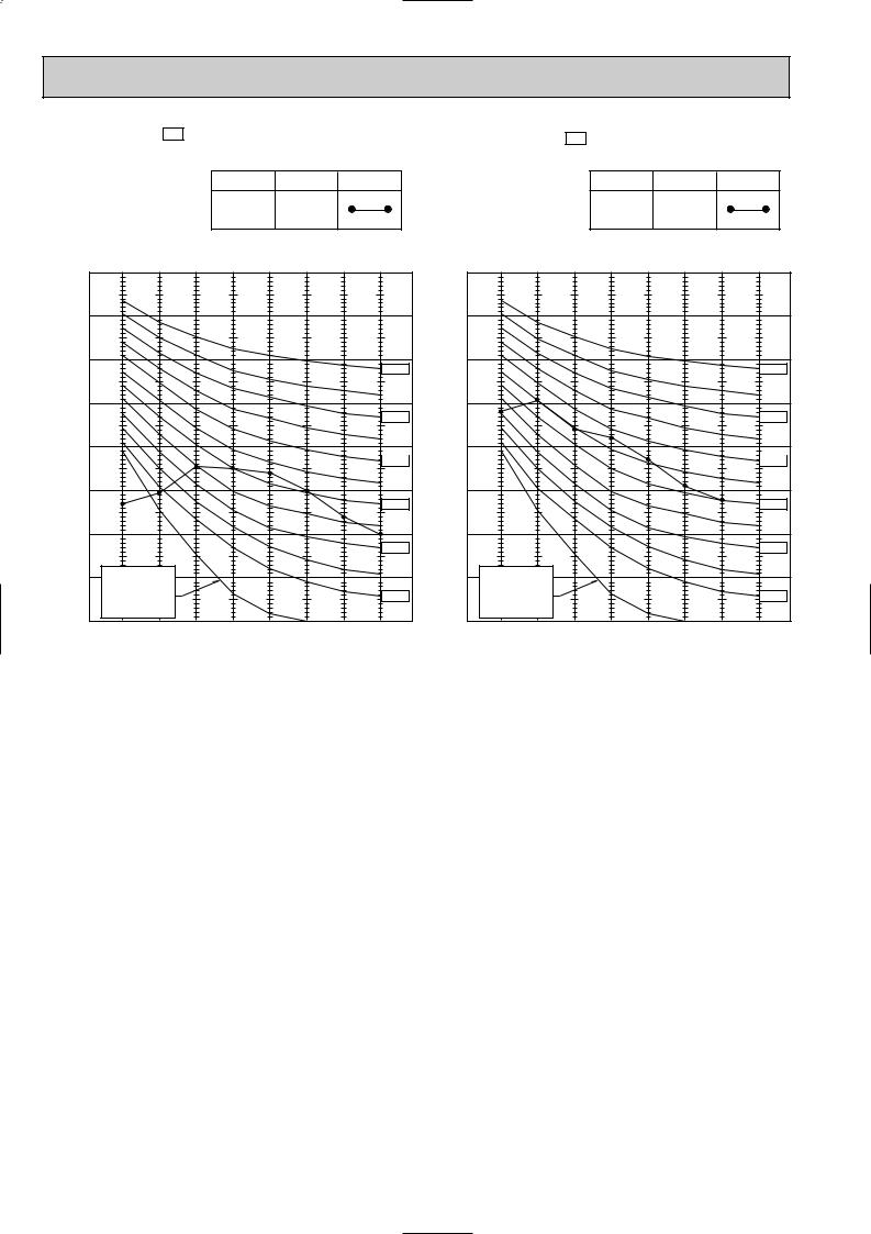
 NOISE CRITERIA CURVES
MCF-C13UV - E1 |
|
|
|
|
|
MUCF-C13UV - E1 |
|
|
|
|
|
||
|
NOTCH |
SPL(dB(A)) |
LINE |
|
|
NOTCH |
SPL(dB(A)) |
LINE |
|
||||
|
|
|
|
|
|
|
|
|
|
|
|
|
|
|
High |
44 |
|
|
|
|
|
High |
49 |
|
|
|
|
|
|
|
|
|
|
|
|
||||||
|
|
|
|
|
|
|
|
|
|
|
|
|
|
Test conditions, |
|
|
|
|
|
Test conditions, |
|
|
|
|
|
||
Cooling : Dry-bulb temperature 27: Wet-bulb temperature 19:\ |
Cooling : Dry-bulb temperature 35: Wet-bulb temperature (24:) |
||||||||||||
|
90 |
|
|
|
|
|
|
|
|
|
90 |
BAR |
|
|
|
|
|
|
|
|
|
BAR |
|
MICRO |
80 |
|
|
|
|
|
|
|
|
MICRO |
80 |
|
|
|
|
|
|
|
|
|
|
||
dB re 0.0002 |
70 |
|
|
|
|
|
|
|
NC-70 |
dB re 0.0002 |
70 |
|
|
|
|
|
|
|
|
|
|||
60 |
|
|
|
|
|
|
|
|
60 |
||
LEVEL, |
|
|
|
|
|
|
|
|
LEVEL, |
||
|
|
|
|
|
|
|
|
NC-60 |
|
||
50 |
|
|
|
|
|
|
|
|
50 |
||
PRESSURE |
|
|
|
|
|
|
|
|
PRESSURE |
||
|
|
|
|
|
|
|
|
NC-50 |
|
||
40 |
|
|
|
|
|
|
|
|
40 |
||
|
|
|
|
|
|
|
|
NC-40 |
|
||
SOUND |
|
|
|
|
|
|
|
|
SOUND |
|
|
30 |
|
|
|
|
|
|
|
|
30 |
||
|
|
|
|
|
|
|
|
NC-30 |
|
||
BAND |
|
|
|
|
|
|
|
|
BAND |
|
|
20 |
APPROXIMATE |
|
|
|
|
|
|
20 |
|||
OCTAVE |
THRESHOLD OF |
|
|
|
|
|
|
OCTAVE |
|||
|
|
|
|
|
|
|
|
||||
|
HEARING FOR |
|
|
|
|
|
NC-20 |
|
|||
|
CONTINUOUS |
|
|
|
|
|
|
||||
|
|
|
|
|
|
|
|
||||
10 |
NOISE |
|
|
|
|
|
|
|
10 |
||
|
|
|
|
|
|
|
|
||||
|
63 |
125 |
250 |
500 |
1000 |
2000 |
4000 |
8000 |
|
||
|
|
|
|
||||||||
|
NC-70 |
|
|
NC-60 |
|
|
NC-50 |
|
|
NC-40 |
|
|
NC-30 |
|
APPROXIMATE |
|
|
THRESHOLD OF |
|
|
HEARING FOR |
NC-20 |
|
CONTINUOUS |
||
|
||
NOISE |
|
63 125 250 500 1000 2000 4000 8000
BAND CENTER FREQUENCIES, Hz |
|
BAND CENTER FREQUENCIES, Hz |
|
||||||||
MCF-C18UV - E1 |
|
|
|
|
MUCF-C18UV - E1 |
|
|
|
|
||
|
|
|
|
|
|
|
|
|
|
|
|
|
NOTCH |
SPL(dB(A)) |
LINE |
|
|
NOTCH |
SPL(dB(A)) |
LINE |
|
||
|
High |
48 |
|
|
|
|
High |
52 |
|
|
|
|
|
|
|
|
|
||||||
|
|
|
|
|
|
|
|
|
|
|
|
Test conditions,
Cooling : Dry-bulb temperature 27: Wet-bulb temperature 19:\
|
90 |
|
|
|
|
|
|
|
|
BAR |
|
|
|
|
|
|
|
|
|
MICRO |
80 |
|
|
|
|
|
|
|
|
|
|
|
|
|
|
|
|
|
|
dB re 0.0002 |
70 |
|
|
|
|
|
|
|
NC-70 |
|
|
|
|
|
|
|
|
||
60 |
|
|
|
|
|
|
|
|
|
LEVEL, |
|
|
|
|
|
|
|
|
|
|
|
|
|
|
|
|
|
NC-60 |
|
50 |
|
|
|
|
|
|
|
|
|
PRESSURE |
|
|
|
|
|
|
|
|
|
|
|
|
|
|
|
|
|
NC-50 |
|
40 |
|
|
|
|
|
|
|
|
|
|
|
|
|
|
|
|
|
NC-40 |
|
SOUND |
|
|
|
|
|
|
|
|
|
30 |
|
|
|
|
|
|
|
|
|
|
|
|
|
|
|
|
|
NC-30 |
|
BAND |
|
|
|
|
|
|
|
|
|
20 |
APPROXIMATE |
|
|
|
|
|
|
||
OCTAVE |
THRESHOLD OF |
|
|
|
|
|
|
||
|
|
|
|
|
|
|
|||
|
HEARING FOR |
|
|
|
|
|
NC-20 |
||
|
CONTINUOUS |
|
|
|
|
|
|||
|
|
|
|
|
|
|
|||
10 |
NOISE |
|
|
|
|
|
|
|
|
|
|
|
|
|
|
|
|
||
|
63 |
125 |
250 |
500 |
1000 |
2000 |
4000 |
8000 |
|
|
|
||||||||
BAND CENTER FREQUENCIES, Hz
Test conditions,
|
|
Cooling : Dry-bulb tempreature 35: Wet-bulb temperature (24:) |
|||||||
|
90 |
|
|
|
|
|
|
|
|
BAR |
|
|
|
|
|
|
|
|
|
MICRO |
80 |
|
|
|
|
|
|
|
|
|
|
|
|
|
|
|
|
|
|
dB re 0.0002 |
70 |
|
|
|
|
|
|
|
NC-70 |
|
|
|
|
|
|
|
|
||
60 |
|
|
|
|
|
|
|
|
|
LEVEL, |
|
|
|
|
|
|
|
|
|
|
|
|
|
|
|
|
|
NC-60 |
|
50 |
|
|
|
|
|
|
|
|
|
PRESSURE |
|
|
|
|
|
|
|
|
|
|
|
|
|
|
|
|
|
NC-50 |
|
40 |
|
|
|
|
|
|
|
|
|
|
|
|
|
|
|
|
|
NC-40 |
|
SOUND |
|
|
|
|
|
|
|
|
|
30 |
|
|
|
|
|
|
|
|
|
|
|
|
|
|
|
|
|
NC-30 |
|
BAND |
|
|
|
|
|
|
|
|
|
20 |
APPROXIMATE |
|
|
|
|
|
|
||
OCTAVE |
THRESHOLD OF |
|
|
|
|
|
|
||
|
|
|
|
|
|
|
|||
|
HEARING FOR |
|
|
|
|
|
NC-20 |
||
|
CONTINUOUS |
|
|
|
|
|
|||
|
|
|
|
|
|
|
|||
10 |
NOISE |
|
|
|
|
|
|
|
|
|
|
|
|
|
|
|
|
||
|
63 |
125 |
250 |
500 |
1000 |
2000 |
4000 |
8000 |
|
|
|
||||||||
BAND CENTER FREQUENCIES, Hz
7
MCF-C24UV - E1 |
|
MUCF-C24UV - E1 |
|
NOTCH |
SPL(dB(A)) LINE |
NOTCH |
SPL(dB(A)) LINE |
High |
48 |
High |
53 |
Test conditions,
Cooling : Dry-bulb temperature 27: Wet-bulb temperature 19:\
|
90 |
|
|
|
|
|
|
|
|
BAR |
|
|
|
|
|
|
|
|
|
MICRO |
80 |
|
|
|
|
|
|
|
|
|
|
|
|
|
|
|
|
|
|
dB re 0.0002 |
70 |
|
|
|
|
|
|
|
NC-70 |
|
|
|
|
|
|
|
|
||
60 |
|
|
|
|
|
|
|
|
|
LEVEL, |
|
|
|
|
|
|
|
|
|
|
|
|
|
|
|
|
|
NC-60 |
|
50 |
|
|
|
|
|
|
|
|
|
PRESSURE |
|
|
|
|
|
|
|
|
|
|
|
|
|
|
|
|
|
NC-50 |
|
40 |
|
|
|
|
|
|
|
|
|
|
|
|
|
|
|
|
|
NC-40 |
|
SOUND |
|
|
|
|
|
|
|
|
|
30 |
|
|
|
|
|
|
|
|
|
|
|
|
|
|
|
|
|
NC-30 |
|
BAND |
|
|
|
|
|
|
|
|
|
20 |
APPROXIMATE |
|
|
|
|
|
|
||
OCTAVE |
THRESHOLD OF |
|
|
|
|
|
|
||
|
|
|
|
|
|
|
|||
|
HEARING FOR |
|
|
|
|
|
NC-20 |
||
|
CONTINUOUS |
|
|
|
|
|
|||
|
|
|
|
|
|
|
|||
10 |
NOISE |
|
|
|
|
|
|
|
|
|
|
|
|
|
|
|
|
||
|
63 |
125 |
250 |
500 |
1000 |
2000 |
4000 |
8000 |
|
|
|
||||||||
BAND CENTER FREQUENCIES, Hz
Test conditions,
|
Cooling : Dry-bulb temperature 35: Wet-bulb temperature (24:) |
||||||||
|
90 |
|
|
|
|
|
|
|
|
BAR |
80 |
|
|
|
|
|
|
|
|
MICRO |
|
|
|
|
|
|
|
|
|
|
|
|
|
|
|
|
|
|
|
dB re 0.002 |
70 |
|
|
|
|
|
|
|
NC-70 |
|
|
|
|
|
|
|
|
||
60 |
|
|
|
|
|
|
|
|
|
LEVEL, |
|
|
|
|
|
|
|
|
|
|
|
|
|
|
|
|
|
NC-60 |
|
50 |
|
|
|
|
|
|
|
|
|
PRESSURE |
|
|
|
|
|
|
|
|
|
|
|
|
|
|
|
|
|
NC-50 |
|
40 |
|
|
|
|
|
|
|
|
|
|
|
|
|
|
|
|
|
NC-40 |
|
SOUND |
|
|
|
|
|
|
|
|
|
30 |
|
|
|
|
|
|
|
|
|
|
|
|
|
|
|
|
|
NC-30 |
|
BAND |
|
|
|
|
|
|
|
|
|
20 |
APPROXIMATE |
|
|
|
|
|
|
||
OCTAVE |
THRESHOLD OF |
|
|
|
|
|
|
||
|
|
|
|
|
|
|
|||
|
HEARING FOR |
|
|
|
|
|
NC-20 |
||
|
CONTINUOUS |
|
|
|
|
|
|||
|
|
|
|
|
|
|
|||
10 |
NOISE |
|
|
|
|
|
|
|
|
|
|
|
|
|
|
|
|
||
|
63 |
125 |
250 |
500 |
1000 |
2000 |
4000 |
8000 |
|
|
|
||||||||
BAND CENTER FREQUENCIES, Hz
8
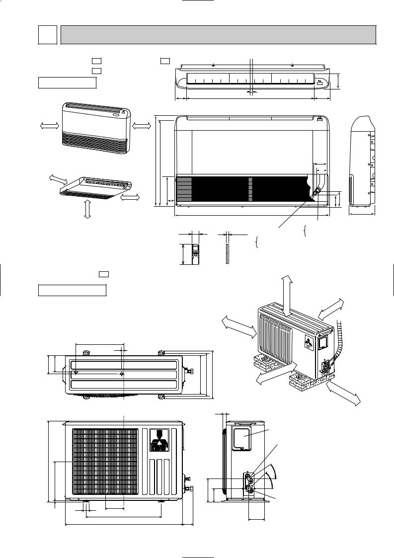
5 OUTLINES AND DIMENSIONS
MCF-C13UV - E1 |
MCF-C18UV - E1 |
MCF-C24UV - E1 |
|
INDOOR UNIT |
|
REQUIRED SPACE |
80.8 |
(When installed on the floor) |
|
500mm or more |
500mm or more |
|
|
650 |
616.5 |
500mm |
(When installed on the ceiling) |
|
|
or |
|
|
|
|
more |
|
170 |
|
|
|
|
|
more |
500mm or more |
42.5 |
|
1000mm or |
|
|
58
Unit: mm
114
906 |
16 |
112.8 |
|
|
|
93 |
|
|
|
|
|
77 |
|
|
|
|
|
|
113 |
143 |
|
|
1100 |
|
|
180 |
|
|
|
Gas line |
|
||
19 |
Liquid line |
[12.7 (MCF-C13UV) |
|||
[15.88 |
(MCF-C18/C24UV) |
||||
|
|||||
MUCF-C13UV - E1
OUTDOOR UNIT
320
15
121 |
109 |
540
260 |
|
|
10 |
40 |
122 |
500
780
[6.35 (MCF-C13/C18UV) [9.52 (MCF-C24UV)
162
Wireless remote controller
|
moreor |
|
|
REQUIRED SPACE |
|
|
|
|
100mm |
or |
more |
100mm |
|
100mm |
|
or |
|
|
|
|
|
|
|
|
more |
|
|
255 |
285 |
320 |
or |
more |
|
|
|
|
|
|
|
|
400mm |
|
350mm |
or |
more |
|
||
|
|
|
|
25 |
|
|
|
|
Service panel |
|
|
|
Liquid refrigerant |
|
|
|
pipe joint |
|
|
|
Refrigerant pipe |
|
|
|
(flared) [6.35 |
|
|
|
- |
|
|
|
35 |
|
|
|
- |
155 |
|
|
43 |
90 |
|
Gas refrigerant |
|
|
|
|
|
|
|
|
pipe joint |
|
|
104 |
Refrigerant pipe |
74 |
|
(flared) [12.7 |
|
|
|
9

MUCF-C18UV - E1 |
MUCF-C24UV - E1 |
|
REQUIRED SPACE |
|
|
|
|
||
OUTDOOR UNIT |
|
|
|
more |
|
|
|
or |
|
|
|
|
|
100mm |
|
|
|
100mm |
or |
|
|
|
|
|
350 |
20 |
|
|
more |
|
|
|
||
35 |
|
|
|
|
248 |
290 |
310 |
345 |
|
|
|
|
|
more |
|
|
|
|
or |
|
|
|
|
500mm |
Drainage 3holes [33
30
Unit: mm
ormore 100mm
350mm |
or |
more |
|
||
|
|
605
20 292
157 |
100 |
50 133
500 |
74 |
850 |
30  35
35
161
Service panel
Liquid refrigerant pipe joint Refrigerant pipe (flared)
[6.35(MUCF-C18UV) [9.52(MUCF-C24UV)
Gas refrigerant pipe joint Refrigerant pipe (flared) [15.88
10
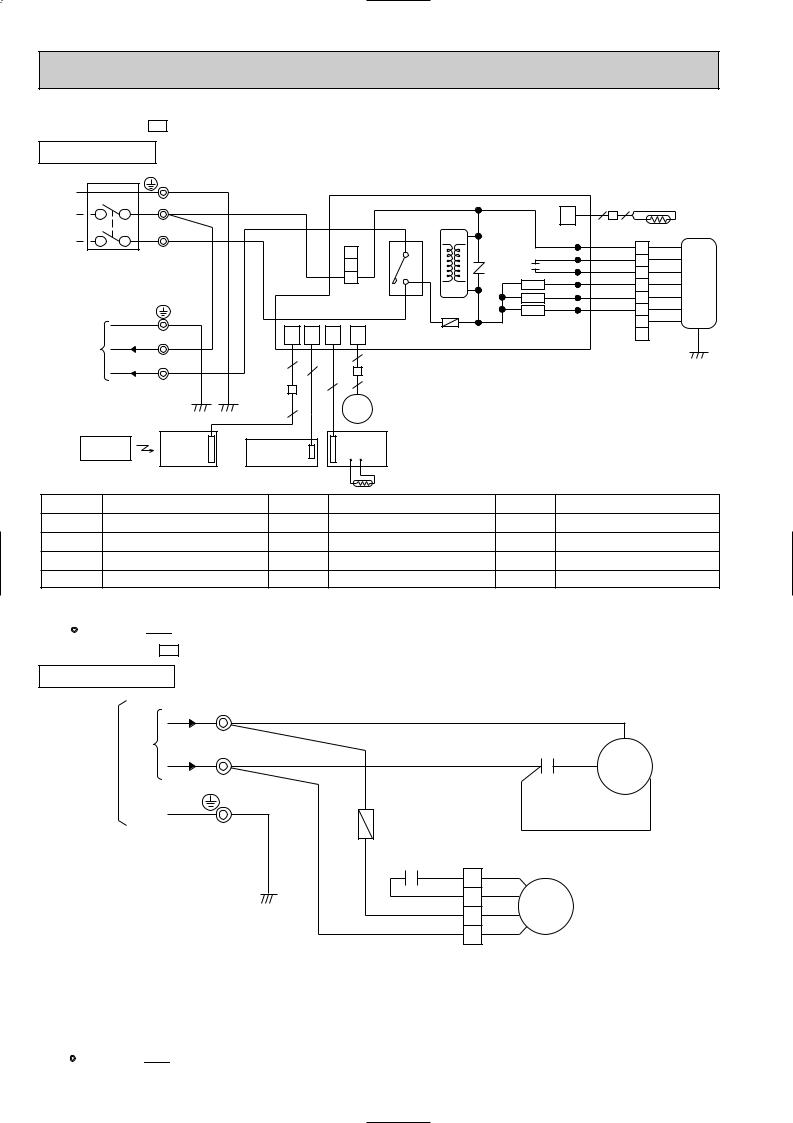
6 |
|
WIRING DIAGRAM |
|
|
|
|
|
|
||||
MCF-C13UV - E1 |
|
|
|
|
|
|
|
|
||||
INDOOR UNIT |
|
|
MODEL WIRING DIAGRAM |
|
|
|
||||||
|
|
|
|
|
|
|
|
|
|
|||
|
CIRCUIT BREAKER |
TB |
|
|
|
|
|
|
|
|
||
|
|
|
|
|
|
|
|
|
|
|
||
|
|
|
|
|
PE GRN/YLW |
|
|
|
|
|
|
|
|
|
N |
|
|
BLU |
|
|
|
|
|
|
|
|
|
|
|
|
|
|
|
|
|
|
|
|
|
|
L |
|
|
|
|
|
|
|
HIC1 |
|
|
|
|
|
|
BRN |
|
|
|
|
|
|
|
|
|
|
|
|
|
|
|
|
|
3 |
4 |
NR11 |
|
|
POWER SUPPLY |
|
|
|
|
|
|
2 |
|
|||
|
|
|
|
|
|
|
52C |
C11 |
||||
|
|
|
|
|
|
|
|
|||||
|
~/N 230V |
|
|
|
|
|
|
1 |
|
|||
|
|
|
|
|
|
|
3 |
|
SR144 |
|||
|
50Hz |
|
|
|
|
|
|
|
|
TRANS |
|
|
|
|
|
|
|
|
|
CN201 |
|
|
|||
|
|
|
|
|
|
|
|
|
|
SR143 |
||
|
|
|
|
|
|
|
|
|
|
|
|
|
|
|
|
|
GRN/YLW |
|
|
|
|
F11 |
|
SR142 |
|
|
|
|
|
|
|
|
|
|
|
|
||
|
|
|
N |
|
CN |
CN |
CN |
CN |
|
|
|
|
TO OUTDOOR |
|
BLU |
101 |
104 |
113 |
151 ELECTRONIC CONTROL P.C BOARD |
||||||
|
|
|
|
|
|
|
|
|
|
|||
UNIT |
|
|
|
|
|
|
|
|
6 |
|
|
|
CONNECTING |
230V~ |
2 |
|
WHT |
|
5 |
|
|
|
|
||
|
|
|
|
5 |
|
|
|
|
||||
|
|
|
|
|
|
|
|
|
||||
|
|
|
|
|
|
|
|
|
|
|
|
|
|
|
|
|
|
|
|
|
4 |
5 |
|
|
|
|
|
|
|
|
|
|
5 |
|
MV |
|
|
|
|
|
|
|
|
|
|
|
|
|
|
|
|
|
REMOTE |
|
DISP/ |
AUTO RESTART |
SW/THERMO |
|
|
|
||||
|
|
RECEIVER |
P.C.BOARD |
|
|
|
||||||
|
CONTROLLER |
|
|
|
|
|
|
|||||
|
|
P.C.BOARD |
ASSY |
|
|
|
|
|
|
|||
|
|
|
|
|
|
|
|
|
|
|||
RT11
CN |
2 2 |
|
|
RT12 |
|
112 |
|
|
|
||
|
|
|
|
||
LDCOM |
WHT 1 |
WHT |
|
||
LDC11 |
ORN |
2 |
ORN |
|
|
LDC12 |
RED |
3 |
RED |
|
|
LDFH |
BLK |
4 |
BLK |
MF |
|
LDFM |
YLW |
YLW |
|||
5 |
|
||||
LDFL |
BLU |
6 |
BLU |
|
|
|
|
|
|
||
7 |
BRN |
|
|
8 |
GRN/YLW |
|
SYMBOL |
NAME |
SYMBOL |
NAME |
SYMBOL |
NAME |
C11 |
INDOOR FAN CAPACITOR |
MV |
VANE MOTOR |
SR142~SR144 |
SOLID STATE RELAY |
|
|
|
|
|
|
F11 |
FUSE (3.15A) |
NR11 |
VARISTOR |
TB |
TERMINAL BLOCK |
|
|
|
|
|
|
HIC1 |
DC/DC CONVERTER |
RT11 |
ROOM TEMPERATURE THERMISTOR |
52C |
CONTACTOR |
|
|
|
|
|
|
MF |
INDOOR FAN MOTOR(INNER PROTECTOR) |
RT12 |
INDOOR COIL THERMISTOR |
|
|
NOTE:1. About the outdoor side electric wiring, refer to the outdoor unit electric wiring diagram for servicing. |
|
VG79B093H02 |
|||
2.Use copper conductors only.(For field wiring)
3.Symbols below indicate;
:Terminal block,


 : Connector
MUCF-C13UV - E1
OUTDOOR UNIT MODEL WIRING DIAGRAM
|
TB |
230V~ 2 |
WHT |
|
WHT |
|
WHT |
|
|
C |
FROM |
|
|
C1 |
|
||
N |
F |
BLU |
|
|
||
INDOOR UNIT |
|
|
||||
|
|
RED |
MC |
|||
CONNECTING |
|
|
|
|
S |
|
|
|
|
|
R |
||
|
|
|
|
|
||
|
|
|
|
|
|
|
|
|
|
|
|
BLK |
|
|
GRN/YLW |
|
C2 |
|
|
|
|
|
|
1 WHT |
|
|
|
|
|
|
WHT |
|
|
|
|
|
|
BLU |
2 BLK |
MF |
|
|
|
|
RED |
3 RED |
|
|
SYMBOL |
NAME |
|
SYMBOL |
NAME |
SYMBOL |
NAME |
C1 |
COMPRESSOR CAPACITOR |
F |
FUSE (2A) |
MF |
OUTDOOR FAN MOTOR (INNER PROTECTOR) |
|
|
|
|
|
|
|
|
C2 |
OUTDOOR FAN CAPACITOR |
MC |
COMPRESSOR (INNER PROTECTOR) |
TB |
TERMINAL BLOCK |
|
NOTES: 1.About the indoor side electric wiring refer to the indoor unit electric wiring diagram for servicing. |
|
VG79B098H02 |
||||
2.Use copper conductors only. (For field wiring) |
|
|
|
|||
3.Symbols below indicate. |
|
|
|
|
|
|
|
: Terminal block |
: Connector |
|
|
|
|
11
MCF-C18UV - E1 |
|
|
|
|
|
|
|
|
||
INDOOR UNIT |
|
MODEL WIRING DIAGRAM |
|
|
|
|||||
CIRCUIT BREAKER |
TB |
|
|
|
|
|
|
|
||
|
|
|
|
|
|
|
|
|
||
|
|
|
PE GRN/YLW |
|
|
|
|
|
|
|
|
N |
|
BLU |
|
|
|
|
|
|
|
|
|
|
|
|
|
|
|
|
|
|
|
L |
|
|
|
|
|
|
HIC1 |
|
|
|
|
BRN |
|
|
|
|
|
|
|
|
|
|
|
|
|
|
|
3 |
4 |
NR11 |
|
POWER SUPPLY |
|
|
|
|
|
2 |
|
|||
|
|
|
|
|
52C |
C11 |
||||
|
|
|
|
|
|
|||||
~/N 230V |
|
|
|
|
|
1 |
|
|||
|
|
|
|
|
3 |
|
SR144 |
|||
50Hz |
|
|
|
|
|
|
|
TRANS |
|
|
|
|
|
|
|
|
CN201 |
|
|
||
|
|
|
|
|
|
|
|
|
SR143 |
|
|
|
|
|
|
|
|
|
|
|
|
|
|
|
GRN/YLW |
|
|
|
|
F11 |
|
SR142 |
|
|
|
|
|
|
|
|
|
|
|
|
|
N |
|
CN |
CN |
CN |
CN |
ELECTRONIC CONTROL P.C BOARD |
||
TO OUTDOOR |
|
BLU |
101 |
104 |
113 |
151 |
||||
|
|
|
|
|
|
|
|
|
||
UNIT |
|
|
|
|
|
|
6 |
|
|
|
CONNECTING |
230V~ |
2 |
WHT |
|
5 |
|
|
|
|
|
|
|
5 |
|
|
|
|
||||
|
|
|
|
|
|
|
||||
|
|
|
|
|
|
|
|
|
|
|
4 5
MV
5
CN |
2 2 |
|
|
RT12 |
|
112 |
|
|
|
||
|
|
|
|
||
LDCOM |
WHT 1 |
WHT |
|
||
LDC11 |
ORN |
2 |
ORN |
|
|
LDC12 |
RED |
3 |
RED |
|
|
LDFH |
BLK |
4 |
BLK |
MF |
|
LDFM |
YLW |
YLW |
|||
5 |
|
||||
LDFL |
BLU |
6 |
BLU |
|
|
|
|
|
|
||
7 |
BRN |
|
|
8 |
GRN/YLW |
|
|
DISP/ |
AUTO RESTART |
SW/THERMO |
|
|
|
REMOTE |
P.C.BOARD |
|
|
|||
|
RECEIVER |
|
|
|
|
|
CONTROLLER |
ASSY |
|
|
|
|
|
|
P.C.BOARD |
|
|
|
|
|
|
|
|
|
RT11 |
|
|
SYMBOL |
NAME |
|
SYMBOL |
NAME |
SYMBOL |
NAME |
C11 |
INDOOR FAN CAPACITOR |
MV |
VANE MOTOR |
SR142~SR144 |
SOLID STATE RELAY |
|
F11 |
FUSE (3.15A) |
|
NR11 |
VARISTOR |
TB |
TERMINAL BLOCK |
HIC1 |
DC/DC CONVERTER |
|
RT11 |
ROOM TEMPERATURE THERMISTOR |
52C |
CONTACTOR |
MF |
INDOOR FAN MOTOR (INNER PROTECTOR) |
RT12 |
INDOOR COIL THERMISTOR |
|
|
|
NOTE:1. About the outdoor side electric wiring, refer to the outdoor unit electric wiring diagram for servicing. |
|
VG79B091H02 |
||||
2.Use copper conductors only.(For field wiring)
3.Symbols below indicate;
:Terminal block,


 : Connector
MUCF-C18UV - E1
OUTDOOR UNIT
FROM INDOOR UNIT CONNECTING |
230V~ |
MODEL WIRING DIAGRAM |
|
|
|
TB |
|
|
|
2 |
|
WHT |
|
WHT |
|
|
C |
|
C1 RED |
|
|
N |
BLU |
MC |
|
|
|
S |
|
|
|
R |
|
|
|
|
F |
BLK |
GRN/YLW |
C2 |
|
RED |
|
|
RED |
1 |
|
|
|
ORN |
2 |
ORN |
MF |
|
WHT |
3 |
WHT |
|
|
BLU |
BLK |
|
|
|
4 |
|
SYMBOL |
NAME |
SYMBOL |
NAME |
SYMBOL |
NAME |
C1 |
COMPRESSOR CAPACITOR |
F |
FUSE (2A) |
MF |
OUTDOOR FAN MOTOR (INNER PROTECTOR) |
|
|
|
|
|
|
C2 |
OUTDOOR FAN CAPACITOR |
MC |
COMPRESSOR (INNER PROTECTOR) |
TB |
TERMINAL BLOCK |
|
|
|
|
|
|
NOTE:1. About the indoor side electric wiring, refer to the indoor unit electric wiring diagram for servicing. |
|
VG79B103H02 |
|||
2.Use copper conductors only.(For field wiring)
3.Symbols below indicate;
:Terminal block,


 : Connector
12
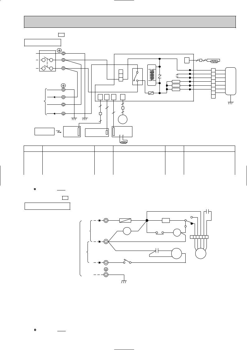
MCF-C24UV - E1 |
|
|
|
|
|
|
|
|
|
|
|
|
|
|
INDOOR UNIT |
MODEL WIRING DIAGRAM |
|
|
|
|
|
|
|
|
|||||
CIRCUIT BREAKER |
TB |
|
|
|
|
|
|
|
|
|
|
|
|
|
|
PE GRN/YLW |
|
|
|
|
|
|
|
|
|
|
|
|
|
N |
BLU |
|
|
|
|
|
|
|
CN |
2 |
2 |
|
RT12 |
|
|
|
|
|
|
|
HIC1 |
|
|
112 |
|
|
|
||
|
|
|
|
|
|
|
|
|
|
|
|
|
||
L |
BRN |
|
|
|
|
|
|
|
|
|
|
|
|
|
|
|
|
|
|
|
|
LDCOM |
|
WHT |
|
WHT |
|
||
|
|
|
|
|
3 |
4 |
|
|
|
1 |
|
|||
POWER SUPPLY |
|
|
|
NR11 |
|
LDC11 |
|
ORN |
2 |
ORN |
|
|||
|
|
|
2 |
52C |
C11 |
|
|
|||||||
|
|
|
LDC12 |
|
RED |
3 |
RED |
|
||||||
~/N 230V |
|
|
|
|
1 |
3 |
SR144 |
LDFH |
|
BLK |
BLK |
MF |
||
50Hz |
|
|
|
CN201 |
TRANS |
|
|
4 |
||||||
|
|
|
|
SR143 LDFM |
|
YLW |
5 |
YLW |
|
|||||
|
GRN/YLW |
|
|
|
|
|
|
|
|
|||||
|
|
|
|
|
F11 |
|
SR142 LDFL |
|
BLU |
6 |
BLU |
|
||
230V~ |
2 WHT |
|
|
|
|
|
|
|
|
|
|
7 |
BRN |
|
CN |
CN |
CN |
CN |
|
|
|
|
|
|
|
|
|||
TO OUTDOOR |
ELECTRONIC CONTROL P.C BOARD |
|
|
8 |
|
|
||||||||
|
101 |
104 |
113 |
151 |
|
|
GRN/YLW |
|||||||
N BLU |
|
|
|
|||||||||||
UNIT |
|
|
|
|
|
|
|
|
|
|
|
|||
5 |
|
|
6 |
|
|
|
|
|
|
|
|
|
||
CONNECTING |
3 |
5 |
|
|
|
|
|
|
|
|
|
|
||
230V~ |
|
|
5 |
|
|
|
|
|
|
|
|
|
||
|
|
4 |
|
|
|
|
|
|
|
|
|
|||
RED |
|
|
|
|
|
|
|
|
|
|
|
|||
|
|
|
|
|
|
|
|
|
|
|
|
|||
|
|
5 |
|
|
MV |
|
|
|
|
|
|
|
|
|
REMOTE |
DISP/ |
AUTO RESTART |
SW/THERMO |
|
|
|
|
|
|
|
|
|||
CONTROLLER |
RECEIVER |
P.C.BOARD |
|
|
|
|
|
|
|
|
||||
ASSY |
|
|
|
|
|
|
|
|
|
|||||
|
P.C.BOARD |
|
|
|
|
|
|
|
|
|
|
|
|
|
|
|
|
|
|
|
RT11 |
|
|
|
|
|
|
|
|
SYMBOL |
NAME |
SYMBOL |
|
|
NAME |
|
SYMBOL |
|
NAME |
|
|
|||
C11 |
INDOOR FAN CAPACITOR |
MV |
VANE MOTOR |
SR142~SR144 |
SOLID STATE RELAY |
|
F11 |
FUSE (3.15A) |
NR11 |
VARISTOR |
TB |
TERMINAL BLOCK |
|
|
|
|
|
|
|
|
HIC1 |
DC/DC CONVERTER |
RT11 |
ROOM TEMPERATURE THERMISTOR |
52C |
CONTACTOR |
|
|
|
|
|
|
|
|
MF |
INDOOR FAN MOTOR (INNER PROTECTOR) |
RT12 |
INDOOR COIL THERMISTOR |
|
|
|
NOTE:1. About the outdoor side electric wiring, refer to the outdoor unit electric wiring diagram for servicing. |
|
VG79B092H03 |
||||
2.Use copper conductors only.(For field wiring)
3.Symbols below indicate;
:Terminal block,


 : Connector
MUCF-C24UV - E1
OUTDOOR UNIT MODEL WIRING DIAGRAM |
C2 |
CONNECTING |
230V~ |
INDOOR UNIT |
230V~ |
FROM |
|
TB |
|
F |
TB2 |
|
|
|
|
X1 |
3 |
|
|
3 |
RED |
RED |
|
GRY 5 |
|
|
|||||
|
RED |
1 |
CR |
|
|
|
|
||||
|
|
|
WHT |
|
|
6 |
|
|
|
|
|
|
|
|
|
|
|
|
1 |
|
|
||
|
A2/b |
A1/a |
|
|
|
|
BLU |
|
|
||
|
|
|
|
|
|
|
|
||||
|
|
RED |
|
RED7 |
8 |
YLW |
BLK WHT ORN |
RED |
|||
|
|
52C |
|
|
|||||||
N |
BLU |
|
|
|
26F1 |
X1 |
|||||
|
|
|
|
6 5 4 3 2 1 |
|||||||
|
|
|
|
|
|
|
|
|
|
|
|
|
|
|
|
BLU |
|
|
|
|
YLW |
BLK WHT ORN |
RED |
|
|
|
|
C1 RED S |
|
|
|||||
|
|
BLU |
C |
|
|
|
|
||||
|
|
|
|
|
|
BLK |
|
|
MF |
|
|
2 |
|
52C |
|
|
|
MC |
|
|
|
||
WHT 2 |
|
|
|
WHT R |
|
|
|
|
|
||
1 |
|
|
|
|
|
|
|
|
|||
|
|
|
|
|
|
|
|
|
|||
GRN/YLW
SYMBOL |
NAME |
SYMBOL |
NAME |
SYMBOL |
NAME |
CR |
CR SURGE ABSORBER |
MC |
COMPRESSOR (INNER PROTECTOR) |
X1 |
FAN MOTOR RELAY |
|
|
|
|
|
|
C1 |
COMPRESSOR CAPACITOR |
MF |
OUTDOOR FAN MOTOR (INNER PROTECTOR) |
26F1 |
THERMOSTAT (AIRFLOW CONTROL) |
|
|
|
|
|
|
C2 |
OUTDOOR FAN CAPACITOR |
TB |
TERMINAL BLOCK |
52C |
COMPRESSOR CONTACTOR |
F |
FUSE (2A) |
TB2 |
TERMINAL BLOCK |
|
|
|
|
|
|
|
|
VG79B104H01
NOTE:1. About the indoor side electric wiring, refer to the indoor unit electric wiring diagram for servicing.
2.Use copper conductors only.(For field wiring)
3.Symbols below indicate;
:Terminal block,


 : Connector
13
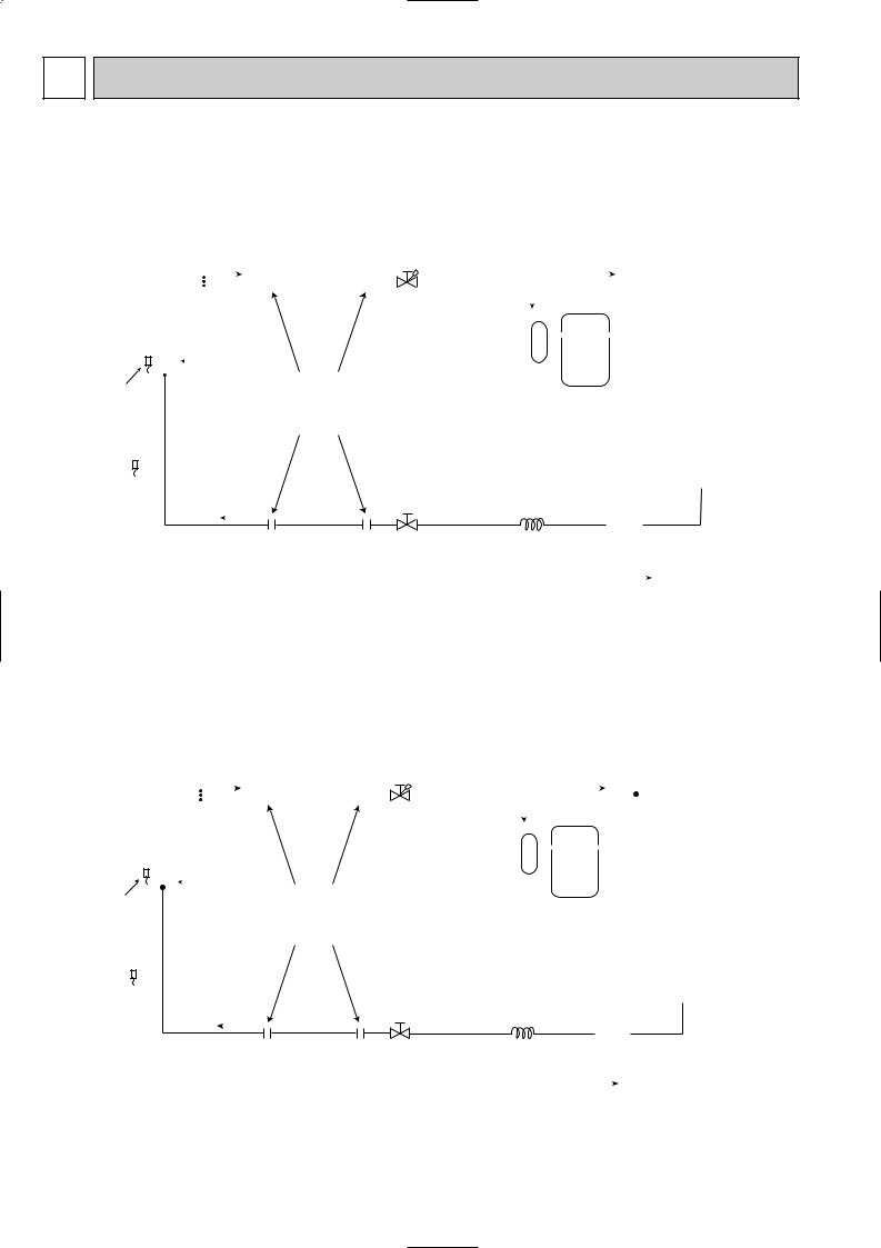
7 REFRIGERANT SYSTEM DIAGRAM
|
|
|
|
|
|
|
|
|
|
|
|
|
|
|
|
|
|
|
|
|
|
|
|
|
|
|
|
|
|
|
|
|
|
|
|
|
|
|
|
|
|
|
|
|
|
|
|
|
|
|
|
|
|
|
|
Unit:mm |
|||
MCF-C13UV - |
|
|
|
|
|
|
|
|
|
|
|
|
|
|
|
|
|
|
|
|
|
|
|
|
|
|
|
|
|
|
|
|
|
|
MUCF-C13UV - |
|
|||||||||||||||||||||||
E1 |
|
|
|
|
|
|
|
|
|
|
|
|
|
|
|
|
|
|
|
|
|
|
|
|
|
|
|
|
|
|
|
|
|
|
|
|
|
|
|
E1 |
|||||||||||||||||||
|
|
|
|
|
|
|
|
|
|
|
|
|
|
Refrigerant pipe |
|
|
|
|
|
|
|
|
|
|
|
|
|
|
|
|
|
|
|
|
|||||||||||||||||||||||||
|
|
|
|
|
|
|
|
|
|
|
|
|
|
|
|
|
|
|
|
|
|
|
|
|
|
|
|
|
|
|
|
||||||||||||||||||||||||||||
|
INDOOR UNIT |
|
|
|
|
|
|
|
|
|
|
|
|
|
|
|
|
|
|
|
|
|
|
|
|
|
|
|
OUTDOOR UNIT |
|
|
||||||||||||||||||||||||||||
|
|
|
|
|
|
|
|
|
|
|
|
|
|
|
|
|
|
|
|
|
|
|
|
|
[12.7 |
|
|
|
|
|
|
|
|
|
|
|
|
|
|
|
|
|
|
|
|
|
|
|
|
|
|
|
|
||||||
|
|
|
Indoor |
|
|
|
|
|
|
|
|
|
|
|
|
|
|
(With heat insulation) |
|
|
|
|
|
|
|
|
|
|
|
|
|
|
|||||||||||||||||||||||||||
|
|
|
|
|
|
|
|
|
|
|
|
|
|
|
|
|
|
|
|
|
|
|
|
|
|
|
|
|
|||||||||||||||||||||||||||||||
|
|
|
|
|
|
|
|
|
|
|
|
|
|
|
|
|
|
|
|
|
|
|
|
|
|
|
|
|
|
|
|
|
|
|
|
|
|
|
|
|
|
|
|
|
|
|
|
||||||||||||
|
|
|
|
|
|
|
|
|
|
|
|
|
|
|
|
|
|
|
|
|
|
|
|
|
|
|
|
Stop valve |
|
|
|
|
|
|
|
|
|
|
|
|
|
|
|
|
|||||||||||||||
|
|
|
|
|
|
|
|
|
|
|
|
|
|
|
|
|
|
|
|
|
|
|
|
|
|
|
|
|
|
|
|
|
|
|
|
|
|
|
|
|
|
|
|
||||||||||||||||
|
|
|
heat |
|
|
|
|
|
|
|
|
|
|
|
|
|
|
|
|
|
|
|
|
|
|
|
|
|
(with service port) |
|
|
|
|
|
|
|
|
|
|
|
|
|
|
|
|||||||||||||||
|
|
|
exchanger |
|
|
|
|
|
|
|
|
|
|
|
|
|
|
|
|
|
|
|
|
|
|
|
|
|
|
|
|
|
|
|
|
|
|
|
|
|
|
|
|
||||||||||||||||
|
|
|
|
|
|
|
|
|
|
|
|
|
|
|
|
|
|
|
|
|
|
|
|
|
|
|
|
|
|
|
|
|
|
|
|
|
|
|
|
|
|
|
|
|
|
|
|
||||||||||||
|
|
|
|
|
|
|
|
|
|
|
|
|
|
|
|
|
|
|
|
|
|
|
|
|
|
|
|
|
|
|
|
|
|
|
|
|
|
|
|
|
|
|
|
|
|
|
|
|
|
|
|
|
|
|
|
Outdoor |
|
|
|
|
|
|
|
|
|
|
|
|
|
|
|
|
|
|
|
|
|
|
|
|
|
|
|
|
|
|
|
|
|
|
|
|
|
|
|
|
|
|
|
|
|
|
|
|
|
|
|
|
|
|
|
|
|
|
|
|
|
|
|
|
|
|
|
|
|
|
|
|
|
|
|
|
|
|
|
|
|
|
|
|
|
|
|
|
|
|
|
|
|
|
|
|
|
|
|
|
|
|
|
|
|
|
|
|
|
|
|
|
|
|
|
|
|
|
|
|
|
|
|
|
|
|
|
|
|
|
|
|
|
|
|
|
|
|
|
|
|
|
|
|
|
|
|
|
|
|
|
|
|
|
|
|
|
|
|
|
|
|
|
|
|
|
|
|
|
|
|
|
|
|
|
|
|
|
|
heat |
|
|
|
|
|
|
|
|
|
|
|
|
|
|
|
|
|
|
|
|
|
|
|
|
|
|
|
|
|
|
|
|
|
|
|
|
|
|
|
|
|
|
|
|
|
|
|
|
|
|
|
||||||||||||
Indoor coil Distributor |
|
|
|
|
|
|
|
|
|
|
Flared |
|
|
|
|
|
|
|
Compressor |
exchanger |
|
|
|
||||||||||||||||||||||||||||||||||||
|
|
|
|
|
|
|
|
|
connection |
|
|
|
|
|
|
|
|
|
|
|
|||||||||||||||||||||||||||||||||||||||
thermistor |
|
|
|
|
|
|
|
|
|
|
|
|
|
|
|
|
|
|
|
|
|
|
|
|
|
|
|
|
|
|
|
||||||||||||||||||||||||||||
RT12 |
|
|
|
|
|
|
|
|
|
|
|
|
|
|
|
|
|
|
|
|
|
|
|
|
|
|
|
|
|
|
|
|
|
|
|
|
|
|
|
||||||||||||||||||||
|
|
|
|
|
|
|
|
|
|
|
|
|
|
|
|
|
|
|
|
|
|
|
|
|
|
|
|
|
|
|
|
|
|
|
|
|
|
|
|
|
|
|
|
|
|
|
|
||||||||||||
|
|
|
|
|
|
|
|
|
|
|
|
|
|
|
|
|
|
|
|
|
|
|
|
|
|
|
|
|
|
|
|
|
|
|
|
|
|
|
|
|
|
|
|
|
|
|
|
|
|
||||||||||
|
|
|
|
|
|
|
|
|
|
|
|
|
|
|
|
|
|
|
|
|
|
|
|
|
|
|
|
|
|
|
|
|
|
|
|
|
|
|
|
|
|
|
|
|
|
|
|
|
|
|
|
|
|
|
|
|
|
|
|
Room |
|
|
|
|
|
|
|
|
|
|
|
|
|
|
|
|
|
|
|
|
|
|
|
|
|
|
|
|
|
|
|
|
|
|
|
|
|
|
|
||||||||||||||||||||
|
|
|
|
|
|
|
|
|
|
|
|
|
|
|
|
|
|
|
|
|
|
|
|
|
|
|
|
|
|
|
|
|
|
|
|
|
|
|
|||||||||||||||||||||
temperature |
|
|
|
|
|
|
|
|
|
|
|
|
|
|
|
|
|
|
|
Stop valve |
|
|
|
|
|
|
|
|
|
|
|
|
|||||||||||||||||||||||||||
|
|
|
|
|
|
|
|
|
|
|
|
|
|
|
|
|
|
|
Strainer |
||||||||||||||||||||||||||||||||||||||||
thermistor |
|
|
|
|
|
|
|
|
|
|
|
|
|
|
|
|
|
|
|
|
|
|
|
Capillary tube |
|
|
|||||||||||||||||||||||||||||||||
|
|
|
|
|
|
|
|
|
|
|
|
|
|
|
|
|
|
|
|
|
|
|
|
||||||||||||||||||||||||||||||||||||
|
|
|
|
|
|
|
|
|
|
|
|
|
|
|
|
|
|
|
|
|
|
|
|
|
|
|
|
|
|
|
|
|
|
|
|
|
|
|
|||||||||||||||||||||
RT11 |
|
|
|
|
|
|
|
|
|
|
|
|
|
|
|
|
|
|
|
|
|
|
|
|
|
|
|
|
|
|
|
|
|
|
|
|
|
|
|
||||||||||||||||||||
|
|
|
|
|
|
|
|
|
|
|
|
|
|
|
|
|
|
|
|
|
|
|
|
|
|
|
Refrigerant pipe |
|
|
|
|
|
|
[3.0 [1.6 600 |
|
|
|
|
|
|
|
|
|
|
|
|
|||||||||||||
|
|
|
|
|
|
|
|
|
|
|
|
|
|
|
|
|
|
|
|
|
|
|
|
|
|
|
|
|
|
|
|
|
|
|
|
|
|
|
|
|
|
|
|
||||||||||||||||
|
|
|
|
|
|
|
|
|
|
|
|
|
|
|
|
|
|
|
|
|
|
|
|
|
|
|
|
|
|
|
|
|
|
|
|
|
|
|
|
|
|
|
|
||||||||||||||||
|
|
|
|
|
|
|
|
|
|
|
|
|
|
|
|
|
|
|
|
|
|
|
|
|
|
|
|
|
|
|
|
|
|
|
|
|
|
|
|
|
|
|
|
|
|
|
|
|
|
|
|
|
|
|
|||||
|
|
|
|
|
|
|
|
|
|
|
|
|
|
|
|
|
|
|
|
|
|
|
|
|
[6.35 |
|
|
|
|
|
|
|
|
|
|
|
|
|
|
|
|
|
|
|
|
|
|
|
|
|
|
|
|
||||||
|
|
|
|
|
|
|
|
|
|
|
|
|
|
|
|
|
|
|
|
|
|
|
|
|
|
|
|
|
|
|
|
|
|
|
|
|
|
|
|
|
|
|
|
|
|
|
|
|
|
|
|
||||||||
|
|
|
|
|
|
|
|
|
|
|
|
|
|
|
|
|
|
|
|
|
|
|
|
|
|
(With heat insulation) |
|
|
|
|
|
|
|
|
|
|
|
|
|
|
|
|
|
|
Refrigerant flow |
||||||||||||||
|
|
|
|
|
|
|
|
|
|
|
|
|
|
|
|
|
|
|
|
|
|
|
|
|
|
|
|
|
|
|
|
|
|
|
|
|
|
|
|
|
|
|
|
|
|
|
|
|
|
|
|
|
|
|
|
||||
MCF-C18UV - |
E1 |
|
|
|
|
|
|
|
|
|
|
|
|
|
|
|
|
|
|
|
|
|
|
|
|
|
|
|
|
|
|
|
|
|
|
|
|
|
|
|
MUCF-C18UV - |
E1 |
||||||||||||||
|
|
|
|
|
|
|
|
|
|
|
|
|
|
|
|
|
|
|
|
|
|
|
|
|
|
|
|
|
|
|
|
|
|
|||||||||||||||||||||||
|
|
|
|
|
|
|
|
|
|
|
|
|
|
|
|
|
|
|
|
|
|
|
|
|
|
|
|
|
||||||||||||||||||||||||||||
|
INDOOR UNIT |
|
|
|
|
|
|
|
|
|
|
Refrigerant pipe |
|
|
|
|
|
|
|
|
|
|
|
|
|
|
|
|
|
OUTDOOR UNIT |
|
|
||||||||||||||||||||||||
|
|
|
|
|
|
|
|
|
|
|
|
|
|
|
|
|
|
|
|
|
|
|
{15.88 |
|
|
|
|
|
|
|
|
|
|
|
|
|
|
|
|
|
|
|
|
|
|
|
|
|
|
|
|
|
||||
|
|
|
Indoor |
|
|
|
|
|
|
|
|
|
|
|
|
|
(With heat insulation) |
|
|
|
|
|
|
|
|
|
|
|
|
|
||||||||||||||||||||||||||
|
|
|
|
|
|
|
|
|
|
|
|
|
|
|
|
|
|
|
|
|
|
|
|
|
|
|
||||||||||||||||||||||||||||||
|
|
|
|
|
|
|
|
|
|
|
|
|
|
|
|
|
|
|
|
|
|
|
|
|
|
|
||||||||||||||||||||||||||||||
|
|
|
|
|
|
|
|
|
|
|
|
|
|
|
|
|
|
|
|
|
|
|
|
|
|
|
|
|
|
|
|
|
|
|
|
|
|
|
|
|
|
|
|
|
|
|
|
|||||||||
|
|
|
|
|
|
|
|
|
|
|
|
|
|
|
|
|
|
|
|
|
|
|
|
|
|
|
Stop valve |
|
|
|
|
|
|
|
|
|
|
|
|
|
|
|
|
|
||||||||||||
|
|
|
|
|
|
|
|
|
|
|
|
|
|
|
|
|
|
|
|
|
|
|
|
|
|
|
|
|
|
|
|
|
|
|
|
|
|
|
|
|
|
|
|
|||||||||||||
|
|
|
heat |
|
|
|
|
|
|
|
|
|
|
|
|
|
|
|
|
|
|
|
|
|
|
|
|
(with service port) |
|
|
|
|
|
|
|
|
|
|
|
|
|
|
|
|
||||||||||||
|
|
|
exchanger |
|
|
|
|
|
|
|
|
|
|
|
|
|
|
|
|
|
|
|
|
|
|
|
|
|
|
|
|
|
|
|
|
|
|
|
|
|
|
|
|
|||||||||||||
|
|
|
|
|
|
|
|
|
|
|
|
|
|
|
|
|
|
|
|
|
|
|
|
|
|
|
|
|
|
|
|
|
|
|
|
|
|
|
|
|
|
|
|
|
|
|
|
|||||||||
|
|
|
|
|
|
|
|
|
|
|
|
|
|
|
|
|
|
|
|
|
|
|
|
|
|
|
|
|
|
|
|
|
|
|
|
|
|
|
|
|
|
|
|
|
|
|
|
|
|
|
|
Outdoor |
|
|
|
|
|
|
|
|
|
|
|
|
|
|
|
|
|
|
|
|
|
|
|
|
|
|
|
|
|
|
|
|
|
|
|
|
|
|
|
|
|
|
|
|
|
|
|
|
|
|
|
|
|
|
|
|
|
|
|
||
|
|
|
|
|
|
|
|
|
|
|
|
|
|
|
|
|
|
|
|
|
|
|
|
|
|
|
|
|
|
|
|
|
|
|
|
|
|
|
|
|
|
|
|
|
|
|
|
|
|
|
|
|
|
|
||
|
|
|
|
|
|
|
|
|
|
|
|
|
|
|
|
|
|
|
|
|
|
|
|
|
|
|
|
|
|
|
|
|
|
|
|
|
|
|
|
|
|
|
|
|
|
|
|
|
|
|
||||||
|
|
|
|
|
|
|
|
|
|
|
|
|
|
|
|
|
|
|
|
|
|
|
|
|
|
|
|
|
|
|
|
|
|
|
|
|
|
|
|
|
|
|
|
|
|
|
|
|
|
|
|
heat |
|
|
|
|
|
|
|
|
|
|
|
|
|
|
|
|
|
|
|
|
|
|
|
|
|
|
|
|
|
|
|
|
|
|
|
|
|
|
|
|
|
|
|
|
|
|
|
|
|
|
|
|
|
|
|
|
|
|
|
||
Indoor coil Distributor |
|
|
|
|
|
|
|
Flared |
|
|
|
|
|
|
|
Compressor |
exchanger |
|
|
|
||||||||||||||||||||||||||||||||||||
|
|
|
|
|
|
connection |
|
|
|
|
|
|
|
|
|
|
|
|
||||||||||||||||||||||||||||||||||||||
thermistor |
|
|
|
|
|
|
|
|
|
|
|
|
|
|
|
|
|
|
|
|
|
|
|
|
|
|
|
|
|
|||||||||||||||||||||||||||
RT12 |
|
|
|
|
|
|
|
|
|
|
|
|
|
|
|
|
|
|
|
|
|
|
|
|
|
|
|
|
|
|
|
|
|
|
|
|
|
|||||||||||||||||||
|
|
|
|
|
|
|
|
|
|
|
|
|
|
|
|
|
|
|
|
|
|
|
|
|
|
|
|
|
|
|
|
|
|
|
|
|
|
|
|
|
|
|
|
|
|
|
|
|
||||||||
|
|
|
|
|
|
|
|
|
|
|
|
|
|
|
|
|
|
|
|
|
|
|
|
|
|
|
|
|
|
|
|
|
|
|
|
|
|
|
|
|
|
|
|
|
|
|
|
|
|
|
||||||
|
|
|
|
|
|
|
|
|
|
|
|
|
|
|
|
|
|
|
|
|
|
|
|
|
|
|
|
|
|
|
|
|
|
|
|
|
|
|
|
|
|
|
|
|
|
|
|
|
|
|
|
|
|
|
|
|
|
|
|
|
|
|
|
|
|
|
|
|
|
|
|
|
|
|
|
|
|
|
|
|
|
|
|
|
|
|
|
|
|
|
|
|
|
|
|
|
|
|
|
|
|
|
|
|
|
|
|
|
|
|
|
|
|
Room |
|
|
|
|
|
|
|
|
|
|
|
|
|
|
|
|
|
|
|
|
|
|
|
|
|
|
|
|
|
|
|
|
|
|
|
|
|
|||||||||||||||||||
temperature |
|
|
|
|
|
|
|
|
|
|
|
|
|
|
|
|
|
Stop valve |
|
|
|
|
|
|
|
|
|
|
|
|||||||||||||||||||||||||||
|
|
|
|
|
|
|
|
|
|
|
Strainer |
|
|
|
|
|||||||||||||||||||||||||||||||||||||||||
thermistor |
|
|
|
|
|
|
|
|
|
|
|
|
|
|
|
|
|
|
|
|
|
|
Capillary tube |
|
|
|
||||||||||||||||||||||||||||||
|
|
|
|
|
|
|
|
|
|
|
|
|
|
|
|
|
|
|
|
|
|
|
|
|||||||||||||||||||||||||||||||||
|
|
|
|
|
|
|
|
|
|
|
|
|
|
|
|
|
|
|
|
|
|
|
|
|
|
|
|
|
|
|
|
|
|
|
|
|
|
|||||||||||||||||||
RT11 |
|
|
|
|
|
|
|
|
|
|
|
|
|
|
|
|
|
|
|
|
|
|
|
|
|
|
|
|
|
|
|
|
|
|
|
|
|
|||||||||||||||||||
|
|
|
|
|
|
|
|
|
|
|
|
|
|
|
|
|
|
|
|
|
|
|
Refrigerant pipe |
|
|
|
|
|
|
{4.0 {2.4 1200 |
|
|
|
|
|
|
|
|
|
|
|
|||||||||||||||
|
|
|
|
|
|
|
|
|
|
|
|
|
|
|
|
|
|
|
|
|
|
|
|
|
|
|
|
|
|
|
|
|
|
|
|
|
|
|
|
|||||||||||||||||
|
|
|
|
|
|
|
|
|
|
|
|
|
|
|
|
|
|
|
|
|
|
|
|
|
|
|
|
|
|
|
|
|
|
|
|
|
|
|
|
|||||||||||||||||
|
|
|
|
|
|
|
|
|
|
|
|
|
|
|
|
|
|
|
|
|
|
|
{6.35 |
|
|
|
|
|
|
|
|
|
|
|
|
|
|
|
|
|
|
|
|
|
|
|
|
|
|
|
|
|
||||
|
|
|
|
|
|
|
|
|
|
|
|
|
|
|
|
|
|
|
|
|
|
|
|
|
|
|
|
|
|
|
|
|
|
|
|
|
|
|
|
|
|
|
|
|
|
|
|
|
|
|
|
|||||
|
|
|
|
|
|
|
|
|
|
|
|
|
|
|
|
|
|
|
|
|
|
|
|
(With heat insulation) |
|
|
|
|
|
|
|
|
|
|
|
|
|
|
|
Refrigerant flow |
||||||||||||||||
|
|
|
|
|
|
|
|
|
|
|
|
|
|
|
|
|
|
|
|
|
|
|
|
|
|
|
|
|
|
|
|
|
|
|
|
|
|
|||||||||||||||||||
|
|
|
|
|
|
|
|
|
|
|
|
|
|
|
|
|
|
|
|
|
|
|
|
|
|
|
|
|
|
|
|
|
|
|
|
|
|
|
|
|||||||||||||||||
|
|
|
|
|
|
|
|
|
|
|
|
|
|
|
|
|
|
|
|
|
|
|
|
|
|
|
|
|
|
|
|
|
|
|
|
|
|
|
|
|
|
|
|
|
|
|
|
|
|
|
|
|
|
|
|
|
14
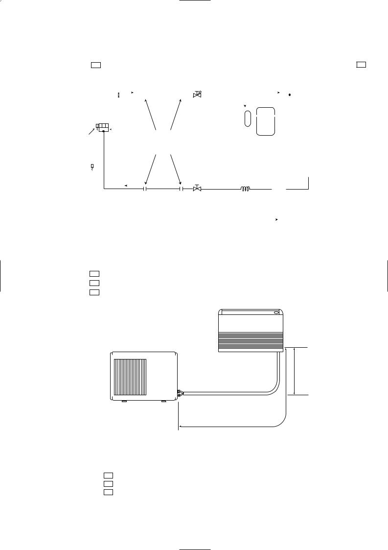
|
|
|
|
|
|
|
|
|
|
|
|
|
|
|
|
|
|
|
|
|
|
|
|
|
|
|
|
|
|
|
|
|
|
|
|
|
|
|
|
|
|
|
|
|
|
|
|
|
|
|
|
|
|
|
|
|
|
|
|
|
|
|
|
|
|
|
|
|
|
|
|
|
|
|
|
|
|
|
|
|
|
|
|
|
|
|
|
|
|
|
|
|
|
|
|
|
|
|
|
|
|
|
|
|
|
|
|
|
|
|
|
|
|
|
|
|
Unit:mm |
MCF-C24UV - E1 |
|
|
|
|
|
|
|
|
|
|
|
|
|
|
|
|
|
|
|
|
|
|
|
|
|
|
|
|
|
|
|
|
|
|
|
|
|
|
MUCF-C24UV - E1 |
|||||||||||||||||||
|
|
|
|
|
|
|
|
|
|
|
Refrigerant pipe |
|
|
|
|
|
|
|
|
|
|
|
|
|
|
|
|
|
|
|
|
|
|
|
||||||||||||||||||||||||
|
INDOOR UNIT |
|
|
|
|
|
|
|
|
|
|
|
|
|
|
|
|
|
|
|
|
|
|
|
|
|
|
|
|
|
|
|
|
OUTDOOR UNIT |
|
|||||||||||||||||||||||
|
|
|
|
|
|
|
|
|
|
|
|
|
|
|
|
|
|
|
{15.88 |
|
|
|
|
|
|
|
|
|
|
|
|
|
|
|
|
|
|
|
|
|
|
|
|
|
|
|
|
|
|
|
|
|
|
|||||
|
|
|
Indoor |
|
|
|
|
|
|
|
|
|
|
|
|
|
|
|
(With heat insulation) |
|
|
|
|
|
|
|
|
|
|
|
|
|
|
|
|
|
|
|
|
|
|
|
|
|||||||||||||||
|
|
|
|
|
|
|
|
|
|
|
|
|
|
|
|
|
|
|
|
|
|
|
|
|
|
|
|
|
|
|
|
|
|
|
|
|
|
|||||||||||||||||||||
|
|
|
|
|
|
|
|
|
|
|
|
|
|
|
|
|
|
|
|
|
|
|
|
|
|
|
|
|
|
|
|
|
|
|
|
|
|
|
|
|
|
|
|
|
|
|
|
|
|
|
|
|
|
|
||||
|
|
|
|
|
|
|
|
|
|
|
|
|
|
|
|
|
|
|
|
|
|
|
|
|
|
|
|
|
Stop valve |
|
|
|
|
|
|
|
|
|
|
|
|
|
|
|
|
|
|
|
|
|||||||||
|
|
|
heat |
|
|
|
|
|
|
|
|
|
|
|
|
|
|
|
|
|
|
|
|
|
|
|
|
|
|
(with service port) |
|
|
|
|
|
|
|
|
|
|
|
|
|
|
|
|
|
|
|
|
||||||||
|
|
|
|
|
|
|
|
|
|
|
|
|
|
|
|
|
|
|
|
|
|
|
|
|
|
|
|
|
|
|
|
|
|
|
|
|
|
|
|
|
|
|
|
|
|
|
|
|
||||||||||
|
|
|
exchanger |
|
|
|
|
|
|
|
|
|
|
|
|
|
|
|
|
|
|
|
|
|
|
|
|
|
|
|
|
|
|
|
|
|
|
|
|
|
|
|
|
|
|
|
|
|
|
|||||||||
|
|
|
|
|
|
|
|
|
|
|
|
|
|
|
|
|
|
|
|
|
|
|
|
|
|
|
|
|
|
|
|
|
|
|
|
|
|
|
|
|
|
|
|
|
|
|
|
|
|
|
|
|
|
|
||||
|
|
|
|
|
|
|
|
|
|
|
|
|
|
|
|
|
|
|
|
|
|
|
|
|
|
|
|
|
|
|
|
|
|
|
|
|
|
|
|
|
|
|
|
|
|
|
|
|
|
|
|
|
|
|
Outdoor |
|
|
|
|
|
|
|
|
|
|
|
|
|
|
|
|
|
|
|
|
|
|
|
|
|
|
|
|
|
|
|
|
|
|
|
|
|
|
|
|
|
|
|
|
|
|
|
|
|
|
|
|
|
|
|
|
|
|
|
|
||
|
|
|
|
|
|
|
|
|
|
|
|
|
|
|
|
|
|
|
|
|
|
|
|
|
|
|
|
|
|
|
|
|
|
|
|
|
|
|
|
|
|
|
|
|
|
|
|
|
|
|
|
|
|
|
|
|
||
|
|
|
|
|
|
|
|
|
|
|
|
|
|
|
|
|
|
|
|
|
|
|
|
|
|
|
|
|
|
|
|
|
|
|
|
|
|
|
|
|
|
|
|
|
|
|
|
|
|
|
|
|||||||
|
|
|
|
|
|
|
|
|
|
|
|
|
|
|
|
|
|
|
|
|
|
|
|
|
|
|
|
|
|
|
|
|
|
|
|
|
|
|
|
|
|
|
|
|
|
|
|
|
|
|
|
|
|
|
heat |
|
|
|
Indoor coil Distributor |
|
|
|
|
|
|
|
Flared |
|
|
|
|
|
|
|
|
|
|
Compressor |
|
|
exchanger |
|
|
||||||||||||||||||||||||||||||||||
|
|
|
|
|
|
connection |
|
|
|
|
|
|
|
|
|
|
|
|
|
|
|
|||||||||||||||||||||||||||||||||||||
thermistor |
|
|
|
|
|
|
|
|
|
|
|
|
|
|
|
|
|
|
|
|
|
|
|
|
|
|
|
|
|
|
|
|
||||||||||||||||||||||||||
RT12 |
|
|
|
|
|
|
|
|
|
|
|
|
|
|
|
|
|
|
|
|
|
|
|
|
|
|
|
|
|
|
|
|
|
|
|
|
|
|
|
|
|
|
||||||||||||||||
|
|
|
|
|
|
|
|
|
|
|
|
|
|
|
|
|
|
|
|
|
|
|
|
|
|
|
|
|
|
|
|
|
|
|
|
|
|
|
|
|
|
|
|
|
|
|
|
|
|
|
|
|
|
|||||
|
|
|
|
|
|
|
|
|
|
|
|
|
|
|
|
|
|
|
|
|
|
|
|
|
|
|
|
|
|
|
|
|
|
|
|
|
|
|
|
|
|
|
|
|
|
|
|
|
|
|
|
|
|
|
|
|||
|
|
|
|
|
|
|
|
|
|
|
|
|
|
|
|
|
|
|
|
|
|
|
|
|
|
|
|
|
|
|
|
|
|
|
|
|
|
|
|
|
|
|
|
|
|
|
|
|
|
|
|
|
|
|
|
|
|
|
|
|
|
|
|
|
|
|
|
|
|
|
|
|
|
|
|
|
|
|
|
|
|
|
|
|
|
|
|
|
|
|
|
|
|
|
|
|
|
|
|
|
|
|
|
|
|
|
|
|
|
|
|
|
|
|
|
|
|
Room |
|
|
|
|
|
|
|
|
|
|
|
|
|
|
|
|
|
|
|
|
|
|
|
|
|
|
|
|
|
|
|
|
|
|
|
|
|
|
|
|
|
|
||||||||||||||||
temperature |
|
|
|
|
|
|
|
|
|
|
|
|
|
|
|
|
|
Stop valve |
|
|
|
|
|
|
|
|
|
|
|
|
|
|
|
|
|
|
|
|
||||||||||||||||||||
|
|
|
|
|
|
|
|
|
|
|
|
|
|
|
|
|
|
|
Strainer |
|
|
|
||||||||||||||||||||||||||||||||||||
|
|
|
|
|
|
|
|
|
|
|
|
|
|
|
|
|
|
|
|
|
|
|
|
|
|
|||||||||||||||||||||||||||||||||
thermistor |
|
|
|
|
|
|
|
|
|
|
|
|
|
|
|
|
|
|
|
|
|
|
|
|
|
|
|
|
|
|
|
|
|
|
|
|||||||||||||||||||||||
|
|
|
|
|
|
|
|
|
|
|
|
|
|
|
|
|
|
|
|
|
|
|
|
|
|
|
|
|
|
|
|
|
||||||||||||||||||||||||||
RT11 |
|
|
|
|
|
|
|
|
|
|
|
|
|
|
|
|
|
|
|
|
|
|
Capillary tube |
|
|
|
|
|
|
|
|
|
|
|
|
|
||||||||||||||||||||||
|
|
|
|
|
|
|
|
|
|
|
|
|
|
|
|
|
|
|
|
|
|
|
|
|
|
|
|
|
|
|
|
|
|
|
||||||||||||||||||||||||
|
|
|
|
|
|
|
|
|
|
|
|
|
|
|
|
|
|
|
|
|
|
|
|
|
|
|
|
|
|
|
|
|
|
|
|
|
|
|
|
|
|
|
|
|
|
|
|
|
|
|
|
|||||||
|
|
|
|
|
|
|
|
|
|
|
|
|
|
|
|
|
|
|
|
|
Refrigerant pipe |
|
|
|
|
|
|
|
|
|
|
|
|
|
|
|
|
|
|
|
|
|
|
|||||||||||||||
|
|
|
|
|
|
|
|
|
|
|
|
|
|
|
|
|
|
|
|
|
|
|
|
|
[4.0 [2.4 1100 |
|
|
|
|
|
|
|
|
|
|
|
|
|
||||||||||||||||||||
|
|
|
|
|
|
|
|
|
|
|
|
|
|
|
|
|
|
|
|
|
|
|
|
|
|
|
|
|
|
|
|
|
|
|
|
|
|
|
|
|
|
|
|
|
|
|
|
|||||||||||
|
|
|
|
|
|
|
|
|
|
|
|
|
|
|
|
|
|
|
{9.52 |
|
|
|
|
|
|
|
|
|
|
|
|
|
|
|
|
|
|
|
|
|
|
|
|
|
|
|
||||||||||||
|
|
|
|
|
|
|
|
|
|
|
|
|
|
|
|
|
|
|
|
|
|
|
|
|
|
|
|
|
|
|
|
|
|
|
|
|
|
|
|
|
|
|
|
|
|
|||||||||||||
|
|
|
|
|
|
|
|
|
|
|
|
|
|
|
|
|
|
|
|
(With heat insulation) |
|
|
|
|
|
|
|
|
|
|
|
|
|
|
|
|
|
|
|
|
|
|
|
|
|
|
||||||||||||
|
|
|
|
|
|
|
|
|
|
|
|
|
|
|
|
|
|
|
|
|
|
|
|
|
|
|
|
|
|
|
|
|
|
|
|
|
|
|
|
|
|
|
|
|
|
|
|
|
|
Refrigerant flow |
||||||||
|
|
|
|
|
|
|
|
|
|
|
|
|
|
|
|
|
|
|
|
|
|
|
|
|
|
|
|
|
|
|
|
|
|
|
|
|
|
|
|
|
|
|
|
|
|
|
|
|
|
|||||||||
REFRIGERANT PIPING MAX. LENGTH & MAX. HEIGHT DIFFERENCE |
||||||||||||||||||||||||||||||||||||||||||||||||||||||||||
|
|
|
|
|
|
|
|
|
|
|
|
|
|
|
|
|
|
|
|
|
|
|
|
|
|
|
|
|
|
|
|
|
|
|||||||||||||||||||||||||
|
|
|
|
|
|
|
|
|
|
|
|
|
|
|
|
|
|
|
|
|
|
|
|
Refrigerant piping |
|
|
|
|
|
Piping size O.D. : mm |
||||||||||||||||||||||||||||
Model |
|
|
|
|
|
|
|
|
Max. length : m |
|
|
|
|
|
|
|
|
|
|
|
|
|
|
|
|
|
|
|
|
|
|
|||||||||||||||||||||||||||
|
|
|
|
|
|
|
|
|
|
Gas |
|
|
|
|
|
|
|
|
|
|
|
Liquid |
||||||||||||||||||||||||||||||||||||
|
|
|
|
|
|
|
|
|
|
|
|
|
|
|
|
|
|
|
|
|
|
|
|
A |
|
|
|
|
|
|
|
|
|
|
|
|
|
|
||||||||||||||||||||
|
|
|
|
|
|
|
|
|
|
|
|
|
|
|
|
|
|
|
|
|
|
|
|
|
|
|
|
|
|
|
|
|
|
|
|
|
|
|
||||||||||||||||||||
MCF-C13UV - E1 |
|
15 |
|
|
|
|
|
|
|
|
|
|
|
|
{12.7 |
|
|
|
|
|
|
|
|
|
|
{6.35 |
||||||||||||||||||||||||||||||||
MCF-C18UV - E1 |
|
|
|
|
|
|
|
|
|
|
|
|
|
|
|
|
{15.88 |
|
|
|||||||||||||||||||||||||||||||||||||||
|
|
|
|
|
|
|
|
|
|
|
|
|
|
|
|
|
|
|
|
|
|
|
|
|
|
|||||||||||||||||||||||||||||||||
MCF-C24UV - E1 |
|
|
|
|
|
|
|
|
|
|
|
|
|
|
|
|
|
|
|
|
|
|
|
|
|
|
|
|
|
|
|
|
|
|
|
{9.52 |
||||||||||||||||||||||
|
|
|
|
|
|
|
|
|
|
|
|
|
|
|
|
|
|
|
|
|
|
|
|
|
|
|
|
|
|
|
||||||||||||||||||||||||||||
Indoor unit
Outdoor unit
*Height difference should be within 5m regardless of which unit, indoor or outdoor position is high.
A: Refrigerant piping Max. length
15m
Max. Height difference * 5m
ADDITIONAL REFRIGERANT CHARGE (R407C : g)
If pipe length exceeds 7m, additional refrigerant (R407C) charge is required.
Model |
Outdoor unit |
|
|
Refrigerant piping length (one way) |
|
||||||
precharged |
|
|
|
|
|
|
|
|
|
||
7m |
8m |
9m |
10m |
11m |
12m |
13m |
14m |
15m |
|||
|
|||||||||||
|
|
||||||||||
MCF-C13UV - E1 |
950 |
0 |
15 |
30 |
45 |
60 |
75 |
90 |
105 |
120 |
|
MCF-C18UV - E1 |
1,100 |
0 |
20 |
40 |
60 |
80 |
100 |
120 |
140 |
160 |
|
MCF-C24UV - E1 |
1,850 |
0 |
20 |
40 |
60 |
80 |
100 |
120 |
140 |
160 |
|
Calculation : MCF-C13UV g=15g/m (Refrigerant piping length (m)-7)
MCF-C18/C24UV g=20g/m (Refrigerant piping length (m)-7)
15
 Loading...