


 Loading...

Introduction
This manual covers the items required for installing and connecting the MITSUBISHI CNC E70 Series. Read this manual thoroughly and understand the product's functions and performance before starting to use.
This manual is written on the assumption that all optional functions are added, but the actually delivered device may not have all functions.
The unit names, cable names and various specifications are subject to change without notice. Please confirm these before placing an order.
This manual notes a reference chapter as "Chapter: Section: Paragraph". (Example) For "1.3.1 List of Units":
"System Configuration: List of Configuration: List of Units"
("1.3.1 List of Units" included in "1.3 List of Configuration" of "1 System Configuration")
CAUTION
For items described as "Restrictions" or "Usable State" in this manual, the instruction manual issued by the machine tool builder takes precedence over this manual.
Items that are not described in this manual must be interpreted as "not possible".
This manual is written on the assumption that all optional functions are added. Confirm the specifications issued by the machine tool builder before starting to use.
Refer to the Instruction Manual issued by each machine tool builder for details on each machine tool.
Some screens and functions may differ depending on each NC system (or version), and some functions may not be possible. Please confirm the specifications before starting to use.
The numerical control unit is configured of the control unit, display unit, operation board (keyboard unit, operation panel I/O unit), servo drive unit, spindle drive unit, power supply unit + driver, servomotor, spindle motor, etc.
In this manual, the following items are generically called "controller".
-Control unit
-Display unit
-operation board (keyboard unit, operation panel I/O unit)
-Numerical control unit peripheral devices (input/output unit, safety unit)
In this manual, the following items are generically called "drive unit".
-Servo drive unit
-Spindle drive unit
-Power supply unit + driver
In this manual, the following items are generically called "motor".
-Servo motor
-Spindle motor
Refer to the following documents.
M700V/M70V/E70 Series PLC Interface Manual .... IB-1500920
MDS-DM2 Series Specifications Manual |
.... IB-1501136 |
MDS-DM2 Series Instruction Manual .... |
IB-1501139 |
MDS-DJ Series Specifications Manual .... |
IB-1501130 |
MDS-DJ Series Instruction Manual .... IB-1501133 |
|
Safety Handbook (Original Instructions) .... |
IB-1501025 |
Precautions for Safety
Always read this manual and enclosed documents before installation, operation, maintenance and inspection to ensure correct usage. Thoroughly understand the basics, safety information and precautions of the devices before using.
This manual classifies the safety precautions into "DANGER", "WARNING" and "CAUTION".
DANGER
When the user could be subject to imminent fatalities or serious injuries if handling is mistaken.
WARNING
When the user could be subject to fatalities or serious injuries if handling is mistaken.
CAUTION
When the user could be subject to injuries or the property could be damaged if handling is mistaken.
Note that the items under "  CAUTION" could lead to serious consequences as well depending on the situation. All the items are important and must always be observed.
The following signs indicate prohibition and compulsory.
This sign indicates prohibited behavior (must not do).
For example, 
 indicates "Keep fire away".
This sign indicated a thing that is pompously (must do).
For example, |
indicates "it must be grounded". |
The meaning of each pictorial sing is as follows.
CAUTION |
CAUTION |
CAUTION |
Danger |
Danger |
|
rotated object |
HOT |
Electric shock risk |
explosive |
|
|
|
|
|
Prohibited |
Disassembly is |
KEEP FIRE AWAY |
General instruction |
Earth ground |
|
prohibited |
|
|
|
For Safe Use
Mitsubishi CNC is designed and manufactured solely for applications to machine tools.
Do not use this product in any applications other than those specified as above, especially those which are substantially influential on the public interest or which are expected to have significant influence on human lives or properties.
We will review the acceptability of the abovementioned applications, if the customer agrees not to require a specific quality for a specific application. Please contact us for consultation.
1. Items related to prevention of electric shocks
WARNING
Do not open or remove the front cover while the power is ON or during operation. The high voltage terminals and charged sections will be exposed, and this could result in electric shocks.
Do not remove the front cover even when the power is OFF, except for the wiring works or periodic inspections. The inside of the controller and drive unit are charged, and this could result in electric shocks.
Always wait at least 15 minutes after turning the power OFF. Then, check the voltage with a tester, etc., before wiring works, inspections or connecting with peripheral devices. Failure to observe this could result in electric shocks.
Earth ground the controller, drive unit and motor according to the local laws. (In Japan, ground the 200V Series input products with Class C or higher protective grounding and the 400V Series input with Class D or higher protective grounding.)
All wiring works, maintenance and inspections must be carried out by a qualified technician. Failure to observe this could result in electric shocks. Contact your nearby Service Center or Service Station for replacing parts and servicing.
Wire the controller, drive unit and motor after installation. Failure to observe this could result in electric shocks.
Do not operate the switches with wet hands. Failure to observe this could result in electric shocks.
Do not damage, apply excessive stress, place heavy things on or sandwich the cables. Failure to observe this could result in electric shocks.
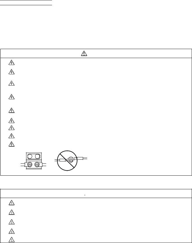
Insulate the power lead using a fixed terminal block. Failure to observe this could result in electric shocks.
2. Items related to prevention of fire
 CAUTION
Install the controller, drive unit, motor and regenerative resistor on non-combustible material. Installation directly on or near combustible materials could result in fires.
If any malfunction in the unit is observed, shut off the power at the unit’s power supply side. Continuous flow of large current could result in fires.
Install an appropriate no fuse breaker (NFB) and contactor (MC) on the power input section of the drive unit and configure the sequence that shuts the power off upon drive unit’s emergency stop or alarm.
When a breaker is shared for multiple power supply units, the breaker may not function upon short-circuit failure in a small capacity unit. Do not share a breaker for multiple units as this is dangerous.
Incorrect wiring and connections could cause the devices to damage or burn.
3. Items related to prevention of bodily injury or property damage
DANGER
When transporting or installing a built-in IPM spindle or linear servomotor, be careful so that your hand or property will not be trapped in the motors or other metal objects. Also keep the devices with low magnetic tolerance away from the product.
 CAUTION
Do not apply voltages to the connectors or terminals other than voltages indicated in the connection manual for the controller or specifications manual for the drive unit. Failure to observe this could cause bursting, damage, etc.
Incorrect connections could cause the devices to rupture or damage, etc. Always connect the cables to the indicated connectors or terminals.
Incorrect polarity (+ -) could cause the devices to rupture or damage, etc.
Persons wearing medical devices, such as pacemakers, must stay away from this unit. The electromagnetic waves could adversely affect the medical devices.
Fins on the rear of the unit, regenerative resistor and motor, etc., will be hot during operation and for a while after the power has been turned OFF. Do not touch or place the parts and cables, etc. close to these sections. Failure to observe this could result in burns.
Do not enter the machine’s movable range during automatic operation. Keep your hands, feet or face away from the spindle during rotation.
4. General precautions
Always follow the precautions below. Incorrect handling could result in faults, injuries or electric shocks, etc.
(1) Transportation and installation
CAUTION
Correctly transport the products according to the mass.
Use motor’s suspension bolts to transport the motor itself. Do not use it to transport the motor after installation onto the machine.
Do not stack the products exceeding the indicated limit.
Do not hold the cables, shaft or detector when transporting the motor.
Do not transport the controller or drive unit by suspending or holding the connected wires or cables.
Do not hold the front cover when transporting the unit, or the front cover could come off, causing the unit to drop.
Install on a non-combustible place where the unit’s or motor’s mass can be withstood according to the instruction manual.
The motor does not have a complete water-proof (oil-proof) structure. Do not allow oil or water to contact or enter the motor. Prevent the cutting chips from being accumulated on the motor as they easily soak up oil.
When installing the motor facing upwards, take measures on the machine side so that gear oil, etc., will not enter the motor shaft.
Do not remove the detector from the motor. (The detector installation screw is treated with sealing.)
Do not allow foreign matters, especially, conductive foreign matters such as screws or metal chips, or combustible foreign matters such as oil, to enter the controller, drive unit or motor. Failure to observe this could result in rupture or damage.
Do not get on the product or place heavy objects on it.
Provide prescribed distance between the controller/drive unit and inner surface of the control panel/other devices.
Do not install or operate the controller, drive unit or motor that is damaged or has missing parts.
Take care not to cut hands, etc. with the heat radiating fins or metal edges.
Do not block the intake/outtake ports of the motor with the cooling fan.
Install the controller’s display section and operation board section on the spot where cutting oil will not reach.
The controller, drive unit and motor are precision devices, so do not drop or apply thumping vibration and strong impacts on them.
Hard disk unit is a precision device, so do not drop or apply strong impacts on it.
Store and use the units according to the environment conditions indicated in each specifications manual.
Securely fix the motor to the machine. The motor could come off during operation if insecurely fixed.
 CAUTION
Always install the motor with reduction gear in the designated direction. Failure to observe this could result in oil leaks.
Always install a cover, etc., over the shaft so that the rotary section of the motor cannot be touched during motor rotation.
When installing a coupling to the servomotor shaft end, do not apply impacts by hammering, etc. The detector could be damaged.
Use a flexible coupling when connecting with a ball screw, etc., and keep the shaft core deviation smaller than the tolerable radial load of the shaft.
Do not use a rigid coupling as an excessive bending load will be applied on the shaft and could cause the shaft to break.
Do not apply a load exceeding the tolerable level onto the motor shaft. The shaft or bearing could be damaged.
Before using this product after a long period of storage, please contact the Mitsubishi Service Station or Service Center.
Following the UN recommendations, battery units and batteries should be transported based on the international regulations such as those determined by International Civil Aviation Organization (ICAO), International Air Transport Association (IATA), International Maritime Organization (IMO) and U.S. Department of Transportation (DOT).

(2) Items related to wiring
CAUTION
Correctly wire this product. Failure to observe this could result in motor runaway, etc.
Do not install a phase advancing capacitor, surge absorber or radio noise filter on the output side of the drive unit.
Correctly connect the output side (terminal U, V, W). The motor will not run properly if incorrectly connected.
Always install an AC reactor per each power supply unit.
Always install an appropriate breaker per each power supply unit. A breaker cannot be shared for multiple power supply units.
Do not directly connect a commercial power supply to the motor. Failure to observe this could result in faults.
When using an inductive load such as relays, always connect a diode in parallel to the load as a noise countermeasure.
When using a capacitive load such as a lamp, always connect a protective resistor serially to the load to suppress rush currents.
Do not mistake the direction of the surge absorption diode to be installed on the DC relay for the control output signal. If mistaken, the signal will not be output due to fault in the drive unit, and consequently the protective circuit, such as emergency stop, could be disabled.
Drive unit |
Drive unit |
COM |
|
COM |
|
(24VDC) |
|
(24VDC) |
|
Control |
|
Control |
|
output |
RA |
output |
|
signal |
signal |
||
|
RA |
Do not connect or disconnect the cables between units while the power is ON.
Do not connect or disconnect the PCBs while the power is ON.
Do not pull the cables when connecting/disconnecting them.
Securely tighten the cable connector fixing screw or fixing mechanism. The motor could come off during operation if insecurely fixed.
Always treat the shield cables indicated in the Connection Manual with grounding measures such as cable clamps.
Separate the signal wire from the drive line or power line when wiring.
Use wires and cables whose wire diameter, heat resistance level and bending capacity are compatible with the system.
Ground the device according to the requirements of the country where the device is to be used.
Wire the heat radiating fins and wires so that they do not contact.
When using the RS-232C device as a peripheral device, caution must be paid for connector connection/ disconnection. Always use a double-OFF type AC power supply switch on the device side, and connect/disconnect the connector with the AC power supply on the device side OFF.
NC unit |
Device |
Switch |
AC socket |
|
RS-232C |
|
|
(3) Adjustments
CAUTION
Check and adjust programs and each parameter before starting operation. Failure to observe this could result in unpredictable operations depending on the machine.
Do not make drastic adjustments or changes as the operation could become unstable.
(4) Usage
 CAUTION
Install an external emergency stop circuit so that the operation can be stopped and the power turns OFF immediately when unforeseen situation occurs. A contactor, etc., is required in addition to the shutoff function mounted in the controller.
Turn OFF the power immediately if any smoke, abnormal noise or odor is generated from the controller, drive unit or motor.
Only a qualified technician may disassemble or repair this product.
Do not alter.
Use a noise filter, etc. to reduce the effect of electromagnetic disturbances in the case where electromagnetic disturbances could adversely affect the electronic devices used near the drive unit.
Use the drive unit, motor and each regenerative resistor with the designated combination. Failure to observe this could result in fires or faults.
The combination of the motor and drive unit that can be used is determined. Be sure to check the models of motor and drive unit before test operation.
The brakes (electromagnetic brakes) mounted in the servomotor are used for the purpose of holding, and must not be used for normal braking. Also, do not run the motor with the motor brake applied. Motor brake is used for the purpose of holding.
For the system running via a timing belt, install a brake on the machine side so that safety can be ensured.
Be sure to confirm SERVO OFF (or READY OFF) when applying the electromagnetic brake. Also, be sure to confirm SERVO ON prior to releasing the brake.
When using the DC OFF type electromagnetic brake, be sure to install a surge absorber on the brake terminal.
Do not connect or disconnect the cannon plug while the electromagnetic brake’s power is ON. The cannon plug pins could be damaged by sparks.
After changing programs/parameters, or after maintenance/inspection, always carry out a test operation before starting actual operation.
Use the power that are complied with the power specification conditions (input voltage, input frequency, tolerable instantaneous power failure time) indicated in each specifications manual.
When making detector cables, do not mistake connection. Failure to observe this could result in malfunction, runaway or fire.
(5) Troubleshooting
CAUTION
Use a motor with electromagnetic brakes or establish an external brake mechanism for the purpose of holding; this serves as countermeasures for possible hazardous situation caused by power failure or product fault.
Use a double circuit structure for the
electromagnetic brake’s operation circuit so that the brakes will activate even when the external emergency stop signal is issued.
Shut off with motor |
Shut off with CNC brake |
|
brake control output |
control PLC output |
|
Motor |
MBR |
EMG |
Electro- |
|
24VDC |
magnetic |
|
|
|
|
|
brake |
|
|
The machine could suddenly restart when the power is restored after an instantaneous power failure, so stay away from the machine. (Design the machine so that the operator safety can be ensured even if the machine restarts.)
To secure the absolute position, do not shut off the servo drive unit’s control power supply when its battery voltage drops (warning 9F) in the servo drive unit side.
If the battery voltage drop warning alarm occurs in the controller side, make sure to back up the machining programs, tool data and parameters, etc. with the input/output device before replacing the battery. Depending on the level of voltage drop, memory loss could have happened. In that case, reload all the data backed up before the alarm occurrence.
(6) Maintenance, inspection and part replacement
CAUTION
Periodically back up the programs, tool data and parameters to avoid potential data loss. Also, back up those data before maintenance and inspections.
When replacing the battery on the controller side, the machining programs, tool data and parameters should be backed up with the input/output device beforehand. In case the memory is damaged in replacing the batteries, reload all the data backed up before replacing the battery.
The electrolytic capacitor’s capacity will drop due to deterioration. To prevent secondary damage due to
capacitor’s faults, Mitsubishi recommends the electrolytic capacitor to be replaced approx. every five years even when used in a normal environment. Contact the Service Center or Service Station for replacements.
Do not perform a megger test (insulation resistance measurement) during inspection.
Do not replace parts or devices while the power is ON.
Do not short-circuit, charge, overheat, incinerate or disassemble the battery.
There may be a unit filled with substitute Freon in the heat radiating fins of the 37kW or smaller unit. Be careful not to break the heat radiating fins during maintenance or replacement.
(7) Disposal
 CAUTION
Take the batteries and backlights for LCD, etc., off from the controller, drive unit and motor, and dispose of them as general industrial wastes.
Do not alter or disassemble controller, drive unit, or motor.
Collect and dispose of the spent batteries and the backlights for LCD according to the local laws.
(8) General precautions
To explain the details, drawings given in the instruction manual, etc., may show the unit with the cover or safety partition removed. When operating the product, always place the cover or partitions back to their original position, and operate as indicated in the instruction manual, etc.
Treatment of waste
The following two laws will apply when disposing of this product. Considerations must be made to each law. The following laws are in effect in Japan. Thus, when using this product overseas, the local laws will have a priority. If necessary, indicate or notify these laws to the final user of the product.
(1)Requirements for "Law for Promotion of Effective Utilization of Resources"
(a)Recycle as much of this product as possible when finished with use.
(b)When recycling, often parts are sorted into steel scraps and electric parts, etc., and sold to scrap contractors. Mitsubishi recommends sorting the product and selling the members to appropriate contractors.
(2)Requirements for "Law for Treatment of Waste and Cleaning"
(a)Mitsubishi recommends recycling and selling the product when no longer needed according to item
(1) above. The user should make an effort to reduce waste in this manner.
(b)When disposing a product that cannot be resold, it shall be treated as a waste product.
(c)The treatment of industrial waste must be commissioned to a licensed industrial waste treatment contractor, and appropriate measures, including a manifest control, must be taken.
(d)Batteries correspond to "primary batteries", and must be disposed of according to local disposal laws.

Disposal
(Note) This symbol mark is for EU countries only.
This symbol mark is according to the directive 2006/66/EC Article 20 Information for endusers and Annex II.
Your MITSUBISHI ELECTRIC product is designed and manufactured with high quality materials and components which can be recycled and/or reused.
This symbol means that batteries and accumulators, at their end-of-life, should be disposed of separately from your household waste.
If a chemical symbol is printed beneath the symbol shown above, this chemical symbol means that the battery or accumulator contains a heavy metal at a certain concentration. This will be indicated as follows:
Hg: mercury (0,0005%), Cd: cadmium (0,002%), Pb: lead (0,004%)
In the European Union there are separate collection systems for used batteries and accumulators. Please, dispose of batteries and accumulators correctly at your local community waste collection/ recycling centre.
Please, help us to conserve the environment we live in!
Trademarks
MELDAS, MELSEC, EZSocket, EZMotion, iQ Platform, MELSOFT, GOT, CC-Link, CC-Link/LT and CC-Link IE are either trademarks or registered trademarks of Mitsubishi Electric Corporation in Japan and/or other countries.
Ethernet is a registered trademark of Xerox Corporation in the United States and/or other countries. Microsoft® and Windows® are either trademarks or registered trademarks of Microsoft Corporation in the United States and/or other countries.
CompactFlash and CF are either trademarks or registered trademarks of SanDisk Corporation in the United States and/or other countries.
UNIX is a registered trademark of The Open Group in the United States and/or other countries.
Intel® and Pentium® are either trademarks or registered trademarks of Intel Corporation in the United States and/or other countries.
Other company and product names that appear in this manual are trademarks or registered trademarks of the respective companies.
( /Japanese)
( A)
Handling of our product
(English)
This is a class A product. In a domestic environment this product may cause radio interference in which case the user may be required to take adequate measures.
( /Korean)
(A ) .
|
Contents |
|
1 System Configuration.................................................................................................................................. |
1 |
|
1.1 |
System Basic Configuration Drawing..................................................................................................... |
2 |
1.2 |
General Connection Diagram ................................................................................................................ |
3 |
1.3 |
List of Configuration ............................................................................................................................... |
5 |
|
1.3.1 List of Units .................................................................................................................................... |
5 |
|
1.3.2 Durable Parts................................................................................................................................. |
6 |
|
1.3.3 Replacements................................................................................................................................ |
6 |
|
1.3.4 List of Cables ................................................................................................................................. |
7 |
2 General Specifications ................................................................................................................................ |
9 |
|
2.1 |
Environment Conditions....................................................................................................................... |
10 |
2.2 |
Control Unit .......................................................................................................................................... |
11 |
2.3 |
Display Unit.......................................................................................................................................... |
21 |
2.4 |
Keyboard Unit ...................................................................................................................................... |
22 |
2.5 |
Operation Panel I/O Unit...................................................................................................................... |
24 |
2.6 |
Remote I/O Unit ................................................................................................................................... |
36 |
2.7 |
External Power Supply Unit ................................................................................................................. |
43 |
2.8 |
Manual Pulse Generator ...................................................................................................................... |
45 |
2.9 |
Synchronous Feed Encoder ................................................................................................................ |
47 |
2.10 MITSUBISHI CNC Machine Operation Panel .................................................................................... |
48 |
|
|
2.10.1 MITSUBISHI CNC Machine Operation Panel A......................................................................... |
48 |
|
2.10.2 MITSUBISHI CNC Machine Operation Panel B......................................................................... |
55 |
2.11 Exclusive CF Cards for MITSUBISHI CNC........................................................................................ |
59 |
|
|
2.11.1 Precautions for Use of Commercially Available CF Cards......................................................... |
59 |
3 Installation .................................................................................................................................................. |
61 |
|
3.1 |
Heat Radiation Countermeasures........................................................................................................ |
62 |
3.2 |
Noise Countermeasures ...................................................................................................................... |
65 |
|
3.2.1 Connection of FG (Frame Ground) .............................................................................................. |
65 |
|
3.2.2 Shield Clamping of Cables........................................................................................................... |
66 |
|
3.2.3 Connecting Spark Killers.............................................................................................................. |
66 |
3.3 |
Unit Installation .................................................................................................................................... |
67 |
|
3.3.1 Display Unit.................................................................................................................................. |
67 |
|
3.3.2 Keyboard Unit .............................................................................................................................. |
68 |
|
3.3.3 Operation Panel I/O Unit.............................................................................................................. |
68 |
|
3.3.4 Control Unit Battery...................................................................................................................... |
69 |
4 Connection ................................................................................................................................................. |
71 |
|
4.1 |
Precautions for Wiring.......................................................................................................................... |
72 |
|
4.1.1 Precautions when Connecting/Disconnecting Cables ................................................................. |
72 |
|
4.1.2 Precautions for Using Optical Communication Cable .................................................................. |
75 |
|
4.1.2.1 Optical Communication Cable Outline and Parts ................................................................ |
75 |
|
4.1.2.2 Precautions for Handling Optical Communication Cable..................................................... |
75 |
|
4.1.2.3 Precautions for Laying Optical Communication Cable ........................................................ |
76 |
|
4.1.3 Precautions for Connecting 24V Power Supply........................................................................... |
76 |
4.2 |
Connection of Control Unit................................................................................................................... |
77 |
|
4.2.1 Control Unit Connection System Drawing.................................................................................... |
77 |
|
4.2.2 Connecting with Power Supply .................................................................................................... |
78 |
|
4.2.3 Connecting with Emergency Stop Signal..................................................................................... |
79 |
|
4.2.4 Connecting with Operation Panel I/O Unit ................................................................................... |
81 |
|
4.2.5 Connecting with Drive Unit........................................................................................................... |
82 |
|
4.2.5.1 Connecting with MDS-DM2 Series ...................................................................................... |
83 |
|
4.2.5.2 Connecting with MDS-DJ Series ......................................................................................... |
84 |
|
4.2.6 Connecting with RS-232C Device................................................................................................ |
85 |
|
4.2.7 Connecting with Skip Signal (Sensor).......................................................................................... |
87 |
|
4.2.8 Connecting with Synchronous Feed Encoder/ Manual Pulse Generator..................................... |
89 |
|
4.2.8.1 Handle Numbers.................................................................................................................. |
89 |
|
4.2.9 Connecting with Safety Observing I/O Device ............................................................................. |
90 |
4.3 Connection of Operation Panel I/O Unit............................................................................................... |
91 |
4.3.1 Operation Panel I/O Unit Connection System Drawing ............................................................... |
91 |
4.3.2 Connecting with Keyboard Unit.................................................................................................... |
92 |
4.3.3 Connecting with Manual Pulse Generator (MPG)........................................................................ |
93 |
4.3.3.1 Handle Numbers .................................................................................................................. |
94 |
4.3.4 Connecting with Machine Operation Panel.................................................................................. |
94 |
4.3.4.1 Wiring for 24V Common Input.............................................................................................. |
95 |
4.3.4.2 Wiring for 0V Common Input................................................................................................ |
95 |
4.3.4.3 Wiring for Source Type Output (FCU7-DX621/DX711/DX721/DX731) ............................... |
96 |
4.3.4.4 Outline of Analog Signal Output Circuit ............................................................................... |
97 |
4.4 Connection of Remote I/O Unit ............................................................................................................ |
98 |
4.4.1 Connection and Station No. Setting on Remote I/O Unit ............................................................. |
98 |
4.4.2 Station No. Setting when Using Multiple Remote I/O Units ....................................................... |
100 |
4.4.3 Connecting FCUA-DX101/141 Unit with Machine Control Signal.............................................. |
104 |
4.4.4 Connecting FCUA-DX141 Unit with Analog Input/Output Signal ............................................... |
106 |
4.4.5 Connecting FCUA-DX111 Unit with Machine Control Signal..................................................... |
107 |
4.4.6 Connecting FCUA-DX121 Unit with Machine Control Signal..................................................... |
109 |
4.5 Connection of MITSUBISHI CNC Machine Operation Panel ............................................................. |
111 |
Appendix 1 Cable ........................................................................................................................................ |
115 |
Appendix 1.1 Cable Wire and Assembly.................................................................................................. |
117 |
Appendix 1.2 CNP2E-1 Cable.................................................................................................................. |
119 |
Appendix 1.3 CNP3EZ-2P/CNP3EZ-3P Cable ........................................................................................ |
120 |
Appendix 1.4 CNV22J-K1P / CNV22J-K2P Cable ................................................................................... |
121 |
Appendix 1.5 CNV2E-8P/CNV2E-9P Cable............................................................................................. |
122 |
Appendix 1.6 CNV2E-HP Cable............................................................................................................... |
123 |
Appendix 1.7 CNV2E-K1P / CNV2E-K2P Cable...................................................................................... |
124 |
Appendix 1.8 DG21 Cable ....................................................................................................................... |
125 |
Appendix 1.9 DG22 Cable ....................................................................................................................... |
126 |
Appendix 1.10 DG23 Cable ..................................................................................................................... |
127 |
Appendix 1.11 DG24 Cable ..................................................................................................................... |
128 |
Appendix 1.12 DG25 Cable ..................................................................................................................... |
129 |
Appendix 1.13 F023/F024 Cable ............................................................................................................. |
130 |
Appendix 1.14 F034/F035 Cable ............................................................................................................. |
131 |
Appendix 1.15 F070 Cable....................................................................................................................... |
132 |
Appendix 1.16 F110 Cable....................................................................................................................... |
133 |
Appendix 1.17 F120 Cable....................................................................................................................... |
134 |
Appendix 1.18 F170 Cable....................................................................................................................... |
135 |
Appendix 1.19 F221 Cable....................................................................................................................... |
136 |
Appendix 1.20 F320/F321 Cable ............................................................................................................. |
137 |
Appendix 1.21 F351 Cable....................................................................................................................... |
138 |
Appendix 1.22 FCUA-R030 Cable ........................................................................................................... |
139 |
Appendix 1.23 FCUA-R031 Cable ........................................................................................................... |
140 |
Appendix 1.24 FCUA-R050/R054 Cable.................................................................................................. |
141 |
Appendix 1.25 FCUA-R211 Cable ........................................................................................................... |
142 |
Appendix 1.26 FCUA-R300/FCUA-R301 Cable....................................................................................... |
143 |
Appendix 1.27 G011 Cable ...................................................................................................................... |
145 |
Appendix 1.28 G023/G024 Cable ............................................................................................................ |
146 |
Appendix 1.29 G071 Cable ...................................................................................................................... |
147 |
Appendix 1.30 G300 Cable ...................................................................................................................... |
148 |
Appendix 1.31 G301 Cable ...................................................................................................................... |
149 |
Appendix 1.32 G380 Cable ...................................................................................................................... |
150 |
Appendix 1.33 G395 Cable ...................................................................................................................... |
151 |
Appendix 1.34 G396 Cable ...................................................................................................................... |
152 |
Appendix 1.35 G460 Cable ...................................................................................................................... |
153 |
Appendix 1.36 MR-BKS1CBL-A1-H / MR-BKS1CBL-A2-H Cable ........................................................... |
154 |
Appendix 1.37 MR-PWS1CBL-A1-H / MR-PWS1CBL-A2-H Cable ......................................................... |
155 |
Appendix 1.38 R-TM Terminator Connector ............................................................................................ |
156 |
Appendix 1.39 SH21 Cable...................................................................................................................... |
157 |
Appendix 1.40 SH41 Cable...................................................................................................................... |
158 |
Appendix 1.41 List of Cable Connector Sets ........................................................................................... |
159 |
Appendix 2 EMC Installation Guidelines .................................................................................................. |
161 |
Appendix 2.1 Introduction ........................................................................................................................ |
162 |
Appendix 2.2 EMC Directives .................................................................................................................. |
162 |
Appendix 2.3 EMC Measures .................................................................................................................. |
163 |
Appendix 2.4 Panel Structure .................................................................................................................. |
163 |
Appendix 2.4.1 Measures for Control Panel Body .............................................................................. |
163 |
Appendix 2.4.2 Measures for Door ..................................................................................................... |
164 |
Appendix 2.4.3 Measures for Power Supply....................................................................................... |
164 |
Appendix 2.5 Measures for Wiring in Panel............................................................................................. |
165 |
Appendix 2.5.1 Precautions for Wiring in Panel.................................................................................. |
165 |
Appendix 2.5.2 Shield Treatment of Cables ....................................................................................... |
166 |
Appendix 2.6 EMC Countermeasure Parts.............................................................................................. |
168 |
Appendix 2.6.1 Shield Clamp Fitting................................................................................................... |
168 |
Appendix 2.6.2 Ferrite Core................................................................................................................ |
169 |
Appendix 2.6.3 Surge Absorber.......................................................................................................... |
170 |
Appendix 2.6.4 Selection of Stabilized Power Supply ........................................................................ |
172 |
Appendix 3 Restrictions for Lithium Batteries......................................................................................... |
173 |
Appendix 3.1 Restriction for Packing ....................................................................................................... |
174 |
Appendix 3.1.1 Target Products ......................................................................................................... |
175 |
Appendix 3.1.2 Handling by User ....................................................................................................... |
176 |
Appendix 3.1.3 Reference .................................................................................................................. |
177 |
Appendix 3.2 Products information data sheet (ER battery).................................................................... |
178 |
Appendix 3.3 Issuing Domestic Law of the United States for Primary Lithium Battery Transportation.... |
180 |
Appendix 3.3.1 Outline of Regulation ................................................................................................. |
180 |
Appendix 3.3.2 Target Products ......................................................................................................... |
180 |
Appendix 3.3.3 Handling by User ....................................................................................................... |
180 |
Appendix 3.3.4 Reference .................................................................................................................. |
180 |
Appendix 3.4 Restriction related to EU Battery Directive......................................................................... |
181 |
Appendix 3.4.1 Important Notes ......................................................................................................... |
181 |
Appendix 3.4.2 Information for end-user............................................................................................. |
181 |
Appendix 4 Precautions for Compliance to UL/c-UL Standards ............................................................ |
183 |

1
System Configuration
1

MITSUBISHI CNC

 1 System Configuration
1.1 System Basic Configuration Drawing
Keyboard unit
Display unit
Remote I/O unit
Control unit
Manual pulse
generator
Operation panel
I/O unit
|
Remote I/O |
|
unit |
|
Manual pulse |
Synchronous feed |
generator |
encoder |
|
Servo/Spindle drive units
Motors
(Note 1) Control unit is mounted on the back side of the display unit.
(Note 2) Operation panel I/O unit is mounted on the back side of the keyboard unit.
(Note 3) For the drive unit configuration, refer to the Instruction Manual of the drive unit you use.
2
E70 Series Connection Manual
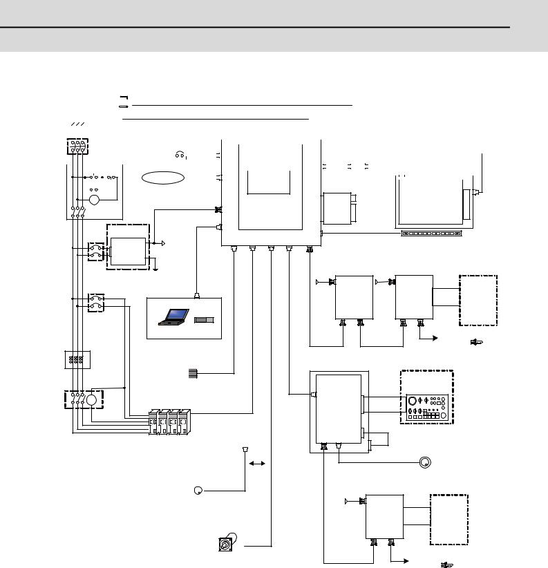
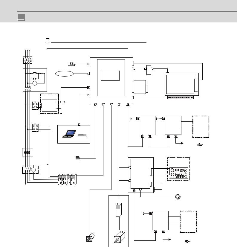
1.2 General Connection Diagram
1.2 General Connection Diagram

 Dotted lines indicate the sections prepared by the machine tool builder.
The name with brackets < > indicates the cable for the unit.
L1 L2 L3
|
|
|
|
|
No-fuse breaker (NFB) |
CNC control unit |
|
|
|
|
|
|
|
|
|
|
|
|
|
|
|
|||||||||||||||||||
|
|
|
|
|
|
|
|
|
|
|
|
|
|
|
|
|
|
|
|
|
|
FCU7-MU558 |
|
|
|
|
|
|
|
|
|
|
|
|
|
|
|
|||
|
|
|
|
|
|
|
|
|
|
|
|
|
EMG |
|
|
|
|
|
|
|
|
|
|
|
|
|
|
|
|
<G497> |
|
|||||||||
|
|
|
|
|
|
|
|
|
|
|
|
|
|
|
|
|
|
|
|
|
|
|
|
|
|
|
|
|
||||||||||||
|
|
|
|
|
|
|
|
|
|
|
|
|
|
|
|
|
|
F120 |
|
|
|
EMG |
Main card HN768 |
LCD |
|
|
|
|
|
|
|
|
|
|||||||
|
|
|
|
|
|
|
|
|
|
|
|
|
|
|
|
|
|
|
|
|
|
|
|
|
|
|
|
|
|
|
|
|
<G487> |
|
||||||
|
|
|
|
|
|
|
|
|
|
|
|
|
|
|
|
|
|
|
|
|
|
|
|
|
|
|
|
|
|
|
|
|
|
|
|
|
||||
|
|
|
|
|
ON OFF |
|
|
|
|
INV |
|
|
|
|
|
|
|
|
|
|
|
|
|
|
||||||||||||||||
|
|
|
|
|
|
|
|
|
|
|
|
|
<G488> |
|
|
|
|
|
|
|
|
|||||||||||||||||||
|
|
|
|
|
|
|
|
|
|
|
|
|
|
|
|
|
|
|
|
|
||||||||||||||||||||
|
|
|
|
|
|
|
|
|
|
|
Ethernet device |
G300/G301 |
|
|
LAN |
|
Memory card |
|
|
|
|
|
|
|
|
|||||||||||||||
|
|
|
|
|
|
|
|
|
|
|
|
|
|
|
|
|
|
|
|
|
|
|
|
|
|
|
|
|
|
|
|
|||||||||
|
|
|
|
|
MC |
|
|
|
|
|
|
|
|
|
|
|
|
|
|
|
|
|
|
|
|
|
|
|
|
|
|
|
|
|||||||
|
|
|
|
|
|
|
|
|
HN441 |
|
|
|
|
LED driver : HN281 |
|
|||||||||||||||||||||||||
|
|
|
|
|
|
|
|
|
|
|
|
|
|
|
|
|
|
|
|
|
|
|
|
|
|
|
|
|
|
|
|
|
|
|
|
|
|
|
|
|
|
|
|
Front |
USB |
Display unit |
MC |
|
FRONT |
FCU7-DU120-13 |
||
|
F070 |
memory |
|
|
|
MC |
DCIN |
I/F card |
CF card I/F |
|
|
|
HN793 |
(VGA:640×480) |
|||
|
|
||||
|
|
|
|
||
|
|
|
|
|
24VDC stabilized |
|
SIO |
|
|
power supply |
|
MENUKEY |
Menu keys |
|
|
DC24V |
SKIP OPT ENC CG71 |
RIO1 |
|
|
|
|
|
|
CP/NFB |
|
|
Remote I/O unit |
Remote I/O unit |
|
FG |
|
||
|
|
DC24V |
DC24V |
|
|
|
|
||
Circuit protector (CP) |
USER 2ch |
|
|
DCIN |
|
DCIN |
|
|
|
|
1ch:F034 |
|
F070 |
|
|
F070 |
|
|
|
|
|
|
2ch:F035 |
|
FCUA-DX1x1 |
FCUA-DX1x1 |
|
Machine |
||||
|
|
|
|
|||||||
RS232C device |
|
|
|
|
|
|
DI-L/R |
control relay/ |
||
|
|
|
|
|
|
|
FCUA- |
contact |
||
|
|
|
|
|
|
|
|
|
||
|
|
|
|
|
|
|
|
|
|
|
CP/NFB |
|
|
|
RIO1 RIO2 |
|
RIO1 |
RIO2 |
R300 |
|
|
|
|
|
|
|
|
|
|
|
/R301 |
|
|
|
|
FCUA-R211 |
FCUA-R211 |
|
|
To the next remote I/O |
|||
AC reactor |
|
|
|
|
or terminator |
|
||||
|
|
/SH41 |
|
/SH41 |
|
|
|
|||
D-AL |
|
|
|
|
|
|
|
|||
|
|
|
|
|
|
|
|
|
|
|
Skip signal input |
|
Keyboard unit |
|
|
|
|
|
|
||
|
FCU7-KB0xx |
|
|
|
|
|
|
|||
Sensor signals |
FCUA-R030 |
|
|
|
|
|
|
|||
|
|
|
|
|
|
|
|
|||
Max.8points |
|
|
Operation panel I/O unit |
|
|
Machine operation |
|
|||
Contactor |
|
|
|
|
panel made by |
|
||||
|
|
FCU7-DX621/7x1 |
|
|
|
|||||
|
|
|
|
|
machine tool builder |
|
||||
|
|
|
G011 |
|
|
|
|
|
|
|
|
|
|
CG71 |
|
|
|
|
|
|
|
|
|
|
max.0.5m |
|
|
|
|
|
|
|
|
1ch G395/G396/G380 |
|
CG3x |
F351 |
|
|
|
|
||
|
|
|
|
|
|
|
|
|
||
|
|
|
|
NCKB |
<G402> |
|
|
|
|
|
Drive units |
|
ENC |
RIO3 MPG |
|
|
|
|
|
|
|
|
|
|
|
|
|
|
|
|
|
|
|
|
Select |
|
|
|
Manual pulse generator |
|
|||
|
|
|
|
|
|
2ch |
|
|
||
|
|
|
|
|
|
|
|
|
||
|
|
|
|
|
12V:F320/F321 |
|
|
|
||
Manual pulse |
|
|
|
5V:F023/F024 |
|
|
|
|||
|
|
|
|
|
|
|
|
|
||
generator |
2ch |
|
Remote I/O unit |
|
|
|
|
|||
|
|
|
|
|
|
|
||||
|
|
|
|
|
|
|
|
|||
|
|
5V:G023/G024 |
|
DC24V |
DCIN |
|
|
|
|
|
|
|
|
|
|
|
|
|
|
|
|
|
|
|
|
F070 |
FCUA-DX1x1 |
|
|
Machine |
|
|
|
|
|
|
|
|
|
|
|||
|
|
FCUA-R050/054 |
|
|
|
|
|
|
|
|
|
|
|
|
|
DI-L/R |
|
|
control relay/ |
|
|
|
|
OSE1024 |
|
|
|
FCUA- |
contact |
|
||
|
1ch |
|
|
|
|
|
||||
|
|
|
RIO1 |
RIO2 |
|
|
||||
|
|
|
|
|
R300 |
|
|
|||
|
|
|
|
|
|
|
/R301 |
|
|
|
|
Synchronous feed encoder |
|
FCUA-R211 |
|
|
|
To the next remote I/O |
|
||
|
|
/SH41 |
|
|
|
|
||||
|
|
|
|
|
|
|
or terminator |
|
||
|
|
|
|
|
|
|
|
|
||
(Note 1) For information on how to connect the drive unit, refer to the drive unit's manual.
(Note 2) For a connection of the MITSUBISHI CNC Machine Operation Panel, refer to "Connection: Connection of MITSUBISHI CNC Machine Operation Panel" to be described.
3
MITSUBISHI CNC

 1 System Configuration
[Analog Spindle Configuration]

 Dotted lines indicate the sections prepared by the machine tool builder.
The name with brackets < > indicates the cable for the unit.
L1 L2 L3
No-fuse breaker (NFB) |
|
|
CNC control unit |
|
|
|
|
|
|
|
|
|
|
|
|
|
FCU7-MU558 |
|
|
|
|
|
|
|
|
|
|
|
EMG |
F120 |
|
|
|
|
LCD |
|
|
|
<G497> |
|
|
|
|
EMG |
|
|
|
|
|
|
|
|
|||
|
|
Main card HN768 |
|
|
|
|
|
|
|||||
|
|
|
|
|
|
|
<G487> |
|
|
|
|||
|
|
|
|
|
|
|
INV |
|
|
|
|
|
|
ON OFF |
|
|
|
|
|
|
|
|
|
|
|
|
|
Ethernet device G300/G301 |
|
|
|
|
<G488> |
|
|
|
|
|
|||
|
LAN |
Memory card |
|
|
|
|
|
||||||
MC |
|
LED driver : HN281 |
|
|
|
||||||||
|
|
|
|
HN441 |
|
|
|
|
|
||||
|
|
|
|
|
|
|
Front |
USB |
Display unit |
|
|
||
MC |
|
|
|
|
|
|
FCU7-DU120-13 |
|
|||||
|
|
F070 |
|
|
|
FRONT memory |
|
|
|
|
|
||
MC |
|
DCIN |
|
|
|
I/F card |
CF card I/F |
|
|
|
|||
|
|
|
|
|
HN793 |
(VGA:640×480) |
|
||||||
|
|
|
|
|
|
|
|||||||
|
|
|
|
|
|
|
|
|
|
||||
|
|
|
|
|
|
|
|
|
|
|
|
||
24VDC stabilized |
|
SIO |
|
|
MENUKEY |
|
|
|
|
|
|
||
power supply |
|
|
|
|
|
|
|
|
Menu keys |
|
|||
DCOUT |
DC24V |
|
SKIP |
OPT |
ENC |
CG71 RIO1 |
|
|
|
|
|||
|
|
|
|
|
|
|
|
|
|
|
|
||
ACIN |
|
|
|
|
|
|
|
|
|
|
|
|
|
FG |
|
|
|
|
|
|
|
|
|
|
|
|
|
CP/NFB |
|
|
|
|
|
|
Remote I/O unit |
Remote I/O unit |
|
|
|||
|
FG |
|
|
|
|
|
|
|
|||||
|
|
|
|
|
|
DC24V |
|
|
DC24V |
|
|
|
|
|
|
|
|
|
|
|
|
|
|
|
|
||
|
|
USER 2ch |
|
|
|
|
DCIN |
DCIN |
|
|
|||
Circuit protector (CP) |
|
1ch:F034 |
|
|
|
F070 |
|
|
F070 |
FCUA-DX1x1 |
|
|
|
|
|
2ch:F035 |
|
|
|
FCUA-DX1x1 |
|
Machine |
|||||
|
|
|
|
|
|
|
|||||||
|
RS232C device |
|
|
|
|
|
|
|
|
DI-L/R |
control relay/ |
||
|
|
|
|
|
|
|
|
|
|
FCUA- |
contact |
||
|
|
|
|
|
|
|
|
|
|
|
|
||
CP/NFB |
|
|
|
|
|
|
|
RIO1 |
RIO2 |
RIO1 RIO2 |
R300 |
|
|
|
|
|
|
|
|
|
|
|
|
|
|
/R301 |
|
|
|
|
|
|
|
|
FCUA-R211 |
|
FCUA-R211 |
|
To the next remote I/O |
||
AC reactor |
|
|
|
|
|
|
|
|
or terminator |
|
|||
|
|
|
|
|
|
/SH41 |
|
|
/SH41 |
|
|
||
D-AL |
|
|
|
|
|
|
|
|
|
|
|
||
|
|
|
|
|
|
|
|
|
|
|
|
|
|
|
Skip signal input |
|
|
|
|
Keyboard unit |
|
|
|
|
|
||
|
|
|
|
|
FCU7-KB0xx |
|
|
|
|
|
|||
|
Sensorsignals |
FCUA-R030 |
|
|
|
|
|
|
|
|
|||
|
|
|
|
|
|
|
|
|
|
|
|||
Contactor |
Max.8points |
|
|
|
|
|
Operation panel I/O unit |
|
Machine operation |
|
|||
|
|
|
|
|
|
|
panel made by |
|
|||||
|
|
|
|
|
|
FCU7-DX621/721 |
|
|
|||||
|
|
|
|
|
|
G011 |
|
machine tool builder |
|
||||
|
|
|
|
|
|
CG71 |
|
|
|
|
|||
MC |
|
|
|
|
|
max.0.5m |
|
|
|
|
|
|
|
|
1ch G395/G396/G380 |
|
|
|
|
|
|
|
|
||||
|
|
|
F221 |
|
CG3x |
F351 |
|
|
|
||||
|
|
|
|
|
|
|
|
|
|
|
|
||
|
|
|
|
|
|
max.30m |
AO |
|
|
|
|
|
|
|
|
|
|
|
|
|
NCKB |
<G402> |
|
|
|
||
|
|
|
FCUA-R050/054 |
|
|
|
|
|
|
||||
|
Drive units |
|
|
|
RIO3 MPG |
|
|
|
|
|
|||
|
|
max.30m |
|
|
|
|
|
|
|
|
|||
|
|
|
|
|
|
|
|
|
|
|
|
|
|
|
|
|
|
|
|
|
|
|
|
Manual pulse generator |
|
||
|
|
|
|
|
|
|
|
|
|
|
2ch |
|
|
|
|
|
|
|
General-purpose inverter |
|
|
12V:F320/F321 |
|
|
|||
|
|
|
|
|
|
|
5V:F023/F024 |
|
|
||||
|
|
|
|
|
|
|
|
|
Remote I/O unit |
|
|
||
|
|
|
|
|
|
|
|
DC24V |
|
|
|
|
|
|
|
|
|
|
|
|
|
|
DCIN |
|
|
|
|
|
|
|
|
|
|
|
|
|
F070 |
FCUA-DX1x1 |
Machine |
|
|
|
|
|
|
|
|
|
|
|
|
|
|||
|
|
|
|
|
|
|
|
|
|
|
|
|
|
|
|
|
|
|
|
|
|
|
|
DI-L/R |
control relay/ |
|
|
|
|
|
|
|
|
|
|
|
|
contact |
|
||
|
|
|
|
|
|
|
|
|
|
|
FCUA- |
|
|
|
|
|
|
|
|
|
|
|
|
RIO1 RIO2 |
|
|
|
|
|
|
|
|
|
|
|
|
|
R300 |
|
|
|
|
|
1ch |
OSE1024 |
|
|
|
|
|
|
/R301 |
|
|
|
|
|
|
|
|
|
|
|
|
|
|
|||
|
|
|
|
|
|
|
FCUA-R211 |
|
To the next remote I/O |
|
|||
|
|
|
|
|
|
|
/SH41 |
|
|
|
|||
|
|
|
|
|
|
|
|
|
or terminator |
|
|||
|
|
|
|
|
|
|
|
|
|
|
|
||
|
|
Synchronous feed encoder |
Spindle motor |
|
|
|
|
|
|
|
|||
(Note 1) For information on how to connect the drive unit, refer to the drive unit's manual.
(Note 2) For a connection of the MITSUBISHI CNC Machine Operation Panel, refer to "Connection: Connection of MITSUBISHI CNC Machine Operation Panel" to be described.
4

E70 Series Connection Manual
1.3 List of Configuration
1.3 List of Configuration
1.3.1 List of Units
|
|
|
|
|
Classification |
Type |
Components |
Remarks |
|
[Control unit] |
|
|
|
|
NC functions |
|
Main control card |
Export Tarde Control Order and Foreign |
|
FCU7-MU558 |
Memory card |
|||
and display controller |
Exchange Order noncompliant unit |
|||
|
Front side memory I/F card |
|||
|
|
|
||
[Display unit] |
|
|
|
|
|
|
LCD panel |
|
|
|
|
Backlight driver |
|
|
8.4-type color TFT |
FCU7-DU120-13 |
Menu keys |
Front side memory I/F is normally equipped |
|
(VGA:640*480) |
Driver cable |
with the control unit |
||
|
||||
|
|
LED backlight cable |
|
|
|
|
LCD cable |
|
|
[Keyboard unit] |
|
|
|
|
Keyboard for 8.4-type display unit |
FCU7-KB024 |
Escutcheon, key switch |
ONG layout (for M system/L system, XYZ) |
|
Sheet keys |
G402 cable |
|||
|
|
|||
Keyboard for 8.4-type display unit |
FCU7-KB025 |
Escutcheon, key switch |
ONG layout (for L system, XZF) |
|
Lathe system sheet keys |
G402 cable |
|||
|
|
|||
[Operation panel I/O unit] |
|
|
|
|
|
|
|
DI: 64-points 24V/0V common type |
|
DI 24V/0V common input |
|
Base card |
DO: 48-points source type |
|
|
MPG:2ch |
|||
DO Source output |
FCU7-DX621 |
Terminator (R-TM) |
||
AO: 1 point |
||||
AO Analog output |
|
Add-on card |
||
|
Occupied stations (fixed): 1, 2, 3, 7, 8 |
|||
|
|
|
||
|
|
|
RIO3 extensible stations: 4, 5, 6 |
|
|
|
|
DI: 64-points 24V/0V common type |
|
DI 24V/0V common input |
|
Base card |
DO: 64-points source type |
|
FCU7-DX711 |
MPG:2ch |
|||
DO Source output |
Terminator (R-TM) |
|||
|
Occupied stations (fixed): 1, 2, 7, 8 |
|||
|
|
|
||
|
|
|
RIO3 extensible stations: 3, 4, 5, 6 |
|
|
|
|
DI: 96-points 24V/0V common type |
|
DI 24V/0V common input |
|
Base card |
DO: 80-points source type |
|
|
MPG:2ch |
|||
DO Source output |
FCU7-DX721 |
Terminator (R-TM) |
||
AO: 1 point |
||||
AO Analog output |
|
Add-on card |
||
|
Occupied stations (fixed): 1, 2, 3, 7, 8 |
|||
|
|
|
||
|
|
|
RIO3 extensible stations: 4, 5, 6 |
|
|
|
|
DI: 96-points 24V/0V common type |
|
DI 24V/0V common input |
|
Base card |
DO: 96-points source type |
|
FCU7-DX731 |
Terminator (R-TM) |
MPG:2ch |
||
DO Source output |
||||
|
Add-on card |
Occupied stations (fixed): 1, 2, 3, 7, 8 |
||
|
|
|||
|
|
|
RIO3 extensible stations: 4, 5, 6 |
|
[Remote I/O unit] |
|
|
|
|
|
|
|
DI: 32-points 24V/0V common type |
|
DI 24V/0V common input |
FCUA-DX101 |
RX312 |
(photo coupler insulation) |
|
DO Source output |
DO: 32-points source type (non-insulation) |
|||
|
|
|||
|
|
|
Number of occupied stations: 1 |
|
|
|
|
DI: 64-points 24V/0V common type |
|
DI 24V/0V common input |
FCUA-DX111 |
RX312+RX322-1 |
(photo coupler insulation) |
|
DO Source output |
DO: 48-points source type (non-insulation) |
|||
|
|
|||
|
|
|
Number of occupied stations: 2 |
|
|
|
|
DI: 64-points 24V/0V common type |
|
DI 24V/0V common input |
|
|
(photo coupler insulation) |
|
DO Source output |
FCUA-DX121 |
RX312+RX322 |
DO: 48-points source type (non-insulation) |
|
AO Analog output |
|
|
AO: 1 point |
|
|
|
|
Number of occupied stations: 2 |
|
|
|
|
DI: 32-points 24V/0V common type |
|
DI 24V/0V common input |
|
|
(photo coupler insulation) |
|
DO Source output |
FCUA-DX141 |
RX312+RX341 |
DO: 32-points source type (non-insulation) |
|
AI Analog input |
AI: 4 points |
|||
|
|
|||
AO Analog output |
|
|
AO: 1 point |
|
|
|
|
Number of occupied stations: 2 |
5
Loading...