


 Loading...
3.0L V6 - VIN [H]
1993 Mitsubishi Montero
1993 CHRYSLER CORP./MITSUBISHI ENGINES
3.0L V6
Dodge: Ram-50
Mitsubishi: Montero, Pickup
ENGINE IDENTIFICATION
NOTE: For engine repair procedures not covered in this article, see ENGINE OVERHAUL PROCEDURES - GENERAL INFORMATION article in the GENERAL INFORMATION section.
Engine may be identified by Vehicle Identification Number (VIN) stamped on a metal pad located near lower left corner of windshield. The eighth character identifies the engine model. Engine code number is stamped on front upper edge of cylinder block, below cylinder head, or on vehicle information plate on firewall. Engine serial number is stamped near the engine code number.
ENGINE IDENTIFICATION CODES TABLE
Application |
Engine Code |
VIN Code |
|
Montero, |
Pickup & Ram-50 |
|
|
3.0L V6 |
....................... |
6G72 ............... |
H |
ADJUSTMENTS
VALVE CLEARANCE ADJUSTMENT
NOTE: All engines are equipped with hydraulic lash adjusters.
Adjustment is not required.
REMOVAL & INSTALLATION
* PLEASE READ FIRST *
CAUTION: When battery is disconnected, vehicle computer and memory systems may lose memory data. Driveability problems may exist until computer systems have completed a relearn cycle.
NOTE: For reassembly reference, label all electrical connectors, vacuum hoses, and fuel lines before removal. Also place mating marks on engine hood and other major assemblies before removal.
FUEL PRESSURE RELEASE
Perform these steps to release fuel system pressure:
*Disconnect fuel pump harness connector at fuel tank.
*Start engine. After it stalls, turn ignition switch to OFF position.
*Disconnect battery (-) terminal. Reconnect fuel pump harness.
*Wrap shop towels around fuel return and high pressure hoses to prevent fuel splashing on engine. Disconnect fuel return hose
and high pressure fuel hose to drain any residual fuel.
ENGINE
Removal
1)Remove hood. Drain cooling system. Remove radiator. Remove skid plate and splash shields. Release fuel system pressure. See FUEL PRESSURE RELEASE. Disconnect negative battery cable.
2)Remove air cleaner ducts. Remove accessory drive belts. Remove and support A/C compressor and power steering pump, leaving hoses connected. Disconnect oil cooler hoses. Cover fuel hose with shop towel, and disconnect high pressure fuel hose and "O" ring.
Disconnect fuel return hose.
3)Label and disconnect all vacuum hoses. Disconnect cooling system hoses. Label and unplug all electrical connections from engine. Remove heat shield from motor mounts. Remove motor mount bolts. Ensure all hoses and wires are disconnected and set aside.
4)Disconnect exhaust pipe from exhaust manifolds. Remove starter. Attach engine hoist to engine. Support transmission. Disconnect engine from transmission. See appropriate information in CLUTCH article in the CLUTCHES section, or refer to procedures described in TRANSMISSION SERVICING - M/T article in the MANUAL TRANSMISSION SERVICING section. Remove engine.
Installation
To install, reverse removal procedure. Install new "O" rings onto fuel lines. Install new exhaust gaskets and nuts. See TORQUE SPECIFICATIONS TABLE at the end of this article. Replenish fluids.
CAUTION: DO NOT allow foreign material into turbocharger air intake hoses or pipes.
INTAKE MANIFOLD
CAUTION: Fuel system is under pressure. Fuel pressure must be released before disconnecting fuel lines. See FUEL PRESSURE RELEASE.
Removal
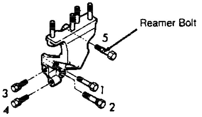
1)Release fuel pressure. Drain cooling system. Remove throttle body. Remove EGR valve and tube (if equipped). Remove front and rear manifold brackets. Remove upper intake manifold. See Fig. 1.
2)Remove spark plug cables, spark plugs, distributor, and coil. Remove fuel pressure regulator, fuel injectors, fuel rails, and grommets. Remove coolant and heater hoses. Remove temperature sensors and thermoswitch. Remove coolant outlet fitting and thermostat. Remove retaining nuts and intake manifold.
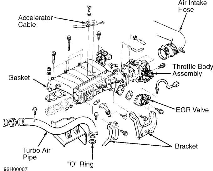
Fig. 1: View Of Typical Upper Intake Manifold Components Courtesy of Mitsubishi Motor Sales of America, Inc.
Installation
Clean all gasket mating surfaces. Inspect for damage and cracks on all mounting surfaces. To install, reverse removal procedure using, new gaskets and "O" rings. Tighten bolts and nuts to specification. See TORQUE SPECIFICATIONS TABLE at the end of this article.
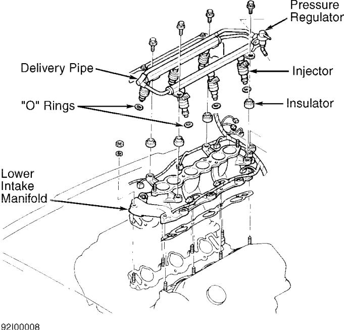
Fig. 2: Exploded View Of Typical Lower Intake Manifold Courtesy of Mitsubishi Motor Sales of America, Inc.
EXHAUST MANIFOLDS
Removal
1)Remove O2 sensor. Disconnect exhaust pipes from manifolds. Lower exhaust pipes. Remove heat shields. Before removing right manifold, remove decking hook and alternator brace.
2)Before removing left exhaust manifold, remove EGR tube (if equipped) and gasket. Remove front intake manifold plenum bracket. Remove exhaust manifolds and gaskets.
Installation
To install, reverse removal procedure. Install new gaskets. Lubricate new dipstick tube "O" ring with engine oil before installation. Install manifold nuts and washers in original locations. On all models, tighten nuts to specification. See TORQUE SPECIFICATIONS TABLE at the end of this article.
CYLINDER HEADS
Removal
1)Drain cooling system. Remove intake manifolds and brackets. See INTAKE MANIFOLD. Remove spark plug wires. Remove splash shields. Disconnect O2 sensor. Remove heat shields and exhaust manifolds. See EXHAUST MANIFOLDS.
2)Remove distributor. Remove timing belt outer covers, camshaft sprockets, timing belt, and timing belt inner covers. See TIMING BELT. Remove accessory bracket bolts from front of cylinder head. Remove rocker cover and gasket.
NOTE: To prevent cylinder head warpage and cracking, loosen cylinder head bolts in 2 or 3 stages in proper sequence.
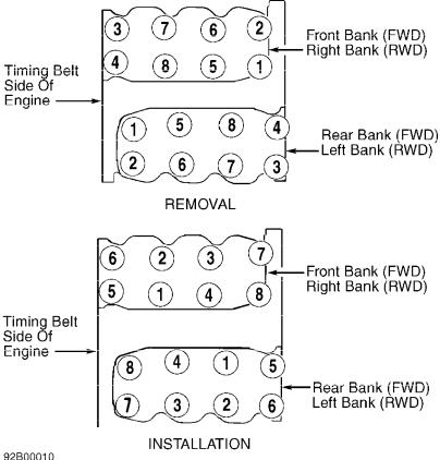
3) Using Socket (MD998051), unscrew cylinder head bolts in 2 or 3 stages in proper sequence. See Fig. 3. Remove cylinder head and camshaft assemblies. Note orientation of washers under cylinder head bolts.
Fig. 3: Removing & Installing Cylinder Head Bolts
Courtesy of Mitsubishi Motor Sales of America, Inc.
Inspection
Measure cylinder head height. Measure warpage at gasket and
manifold surfaces. Resurface head if warpage exceeds specification. See CYLINDER HEAD table under ENGINE SPECIFICATIONS. Replace cylinder head if it is not within specification after resurfacing.
Installation
1)Ensure mating surfaces are clean and dry. Note identification mark located on front of head gasket. Identification mark is "R". Install head gasket with identification mark toward timing belt side of engine, facing upward.
2)Install cylinder head. Install washers cylinder head bolts with chamfered side toward bolt head. Using proper sequence, tighten bolts to specification in 2 or 3 stages in proper sequence. See
Fig. 3. See TORQUE SPECIFICATIONS TABLE at the end of this article.
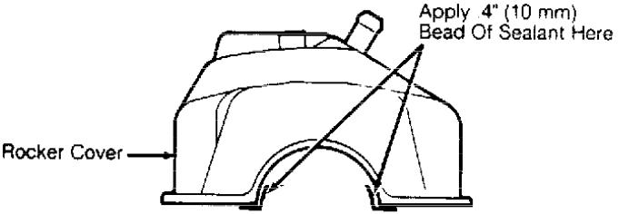
3)Apply sealant to rocker cover sealing surfaces before installation. See Fig. 4. Align rocker cover gasket projections with notches in rocker cover. Lubricate all "O" rings with engine oil before installation. Install new "O" rings onto distributor adapter and oil dipstick tube.
4)Lubricate camshaft area with oil prior to installing distributor adapter. To complete installation, reverse removal procedure. Tighten bolts and nuts to specification. See TORQUE SPECIFICATIONS TABLE at the end of this article. After engine reaches normal operating temperature, allow engine to cool. Retighten cylinder head bolts to specification.
Fig. 4: Applying Sealant To Rocker Cover
Courtesy of Mitsubishi Motor Sales of America, Inc.
FRONT CRANKSHAFT OIL SEAL
Removal & Installation
Remove timing belt and crankshaft sprocket. See TIMING BELT. Pry oil seal from oil pump. Before installation, coat seal lip with grease. Using Seal Driver (MD998717), install seal in oil pump. Install remaining components. See TORQUE SPECIFICATIONS TABLE at the end of this article.
TIMING BELT
Removal
1)Drain cooling system. Disconnect upper radiator hose. Remove upper radiator shroud. Remove cooling fan and fan clutch assembly. Remove cooling fan pulley. Remove drive belts. Remove power steering pump, leaving hoses connected. Set power steering pump aside.
2)Remove power steering pump brackets. Remove A/C tensioner
pulley and mounting bracket. Remove A/C compressor with hoses connected, and remove mounting bracket. Remove cooling fan bracket assembly. Note location and length of bolts for reassembly reference.
NOTE: "V" belt will be damaged by tool. DO NOT use engine "V" belt to hold crankshaft pulley unless belt is to be replaced.
3)Remove upper timing belt covers and gaskets. See Fig. 6. Remove lower timing belt cover and gaskets. Using Holder (MB998747) and a used "V" belt, remove crankshaft pulley bolt. Remove crankshaft pulley.
4)Remove flange. See Fig. 6. Rotate crankshaft to align all timing marks. See Fig. 7. Loosen belt tensioner bolt, and rotate belt tensioner counterclockwise to relieve belt tension.
5)If reusing timing belt, place arrow on belt to indicate belt running direction. Remove timing belt and belt tensioner. If camshaft sprocket requires removal, install Holder (MB990775) onto camshaft sprocket. Remove retaining bolt and camshaft sprocket. Remove rear timing belt cover if necessary.
Fig. 5: Removing Engine Support Bracket
Courtesy of Mitsubishi Motor Sales of America, Inc.
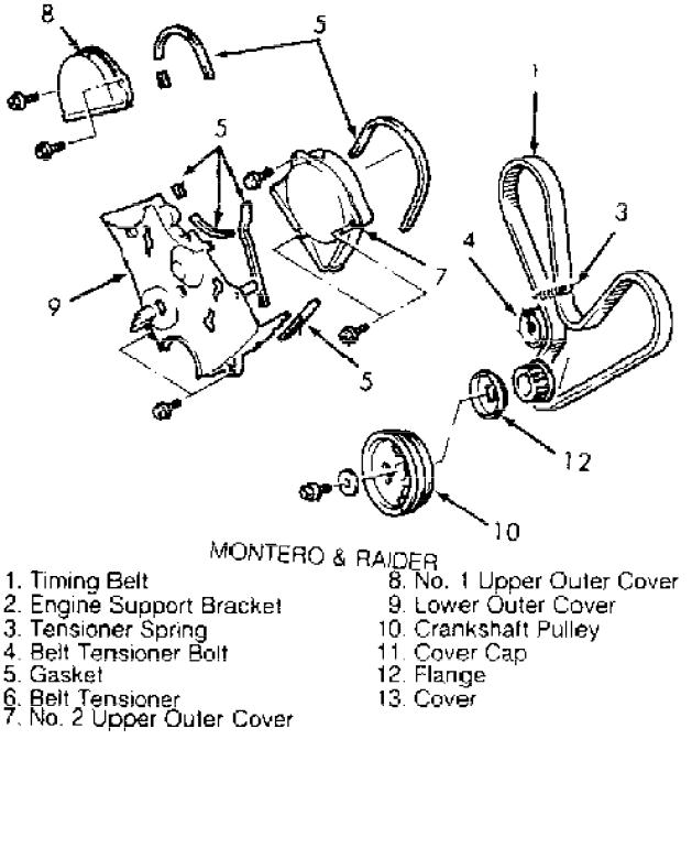
Fig. 6: Exploded View Of Timing Belt Components Courtesy of Mitsubishi Motor Sales of America, Inc.
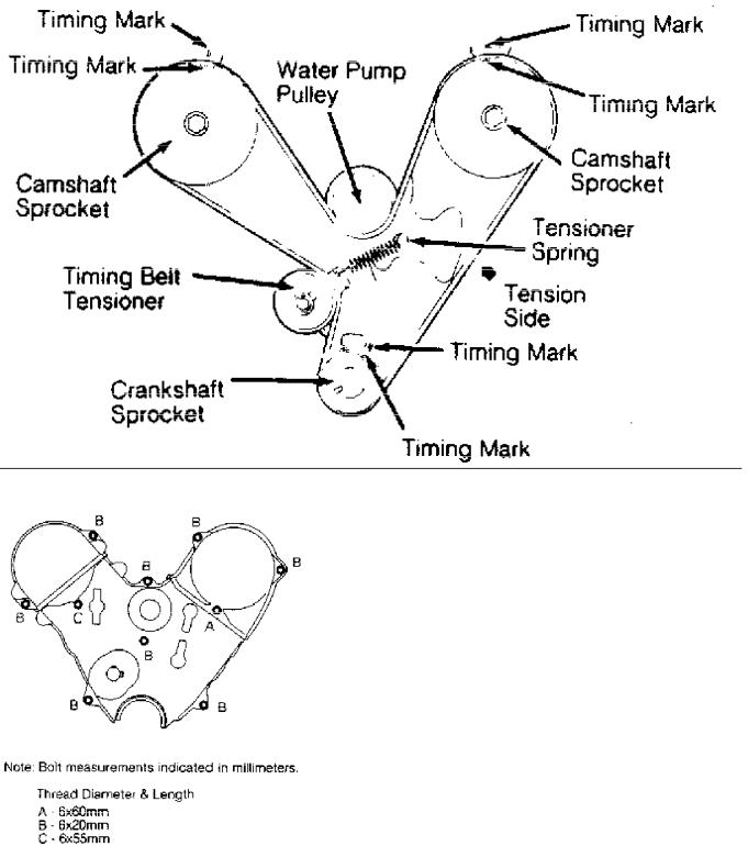
Fig. 7: Aligning Timing Marks
Courtesy of Mitsubishi Motor Sales of America, Inc.
Fig. 8: Identifying Timing Belt Cover Bolt Lengths Courtesy of Mitsubishi Motor Sales of America, Inc.
Installation
1) Install rear timing belt cover. Tighten bolts to
specification. See TORQUE SPECIFICATIONS TABLE at the end of this article. Install camshaft sprockets (if removed). Using holder, hold camshaft and tighten retaining bolt to specification.
2)Install belt tensioner and spring. Ensure spring is secured on pin of water pump and engaged in hole of belt tensioner, with hook of spring pointing away from cylinder block.
3)Rotate belt tensioner counterclockwise as far as possible, and temporarily tighten bolt. Align all timing marks with No. 1 cylinder at TDC of compression stroke. See Fig. 7.
4)Install timing belt onto crankshaft sprocket first, then onto left camshaft sprocket, with all slack removed from tension side of belt. Route timing belt onto water pump pulley, right camshaft sprocket, and tensioner. Remove any slack from belt by rotating left and then right camshaft sprockets counterclockwise.
5)Ensure belt is installed in original direction of rotation, and all timing marks are aligned. Install flange on crankshaft. Loosen belt tensioner bolts slightly, and allow tensioner to apply belt tension.
6)Using Crankshaft Socket (MD998716), rotate crankshaft 2 revolutions clockwise. DO NOT rotate counterclockwise. Realign all timing marks. Tighten belt tensioner bolts to specification. Using belt tension gauge, measure belt tension halfway between crankshaft sprocket and camshaft sprocket on side opposite belt tensioner.
7)Belt tension should be 57-84 lbs. (26-38 kg). To install remaining components, reverse removal procedure. Install bolts in proper holes. See Fig. 8. Tighten bolts to specification. See TORQUE SPECIFICATIONS TABLE at the end of this article.
CAMSHAFT & ROCKER ARMS
Removal
1)Remove PCV valve and breather hoses. Remove timing belt, camshaft sprocket, and rear timing belt cover. See TIMING BELT. Remove rocker covers and gaskets. Remove circular packing from rear of camshafts.
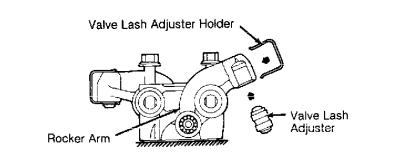
2)Remove camshaft oil seal from front of cylinder head or distributor adapter. Remove distributor adapter and "O" ring. Install Valve Lash Adjuster Holder (MD998443) onto rocker arm. See Fig. 9. Note arrow marks on bearing caps and cylinder head. See Fig. 10.
3)Bearing cap location number is stamped on front side of bearing cap. Remove bearing cap bolts. Keep components in order for reassembly reference. Remove rocker arm assembly. Remove camshaft from cylinder head.
Fig. 9: Installing Valve Lash Adjuster Holder Courtesy of Mitsubishi Motor Sales of America, Inc.

Fig. 10: Identifying Bearing Cap & Sealant Locations Courtesy of Mitsubishi Motor Sales of America, Inc.
Inspection
1) Remove bearing caps, rocker arms, and springs from shafts. Mark component location for reassembly reference. Inspect rocker arm and shaft for damaged roller and flaking. Measure rocker arm I.D. and rocker arm shaft O.D. Determine oil clearance. Measure spring free length. Replace components if not within specification. See ROCKER ARM & SHAFT SPECIFICATIONS table.
2)Inspect camshaft and distributor gear for damage. Measure camshaft end play, journal diameter, and lobe height. Replace camshaft if it is not within specification. See CAMSHAFT table under ENGINE SPECIFICATIONS.
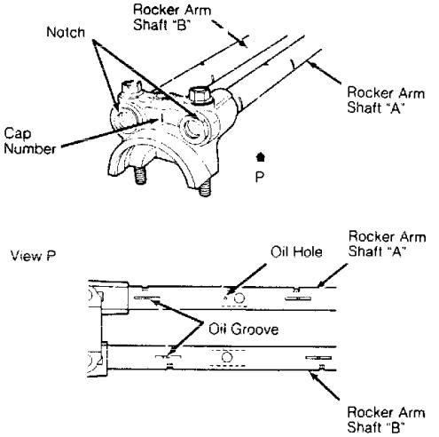
3)Lubricate components with engine oil. Reassemble rocker arms, springs, and bearing caps. Install bearing caps with identification number toward camshaft sprocket. Ensure oil holes and notch of shafts are properly positioned. See Fig. 11.
ROCKER ARM & SHAFT SPECIFICATIONS TABLE
Application |
|
|
In. (mm) |
|
Oil Clearance ................ |
(1) .0004-.0016 (.010-.041) |
|||
Rocker Arm I.D. ............................ |
.7444 |
(18.91) |
||
Rocker |
Arm Shaft O.D. |
...................... |
.7440 |
(18.90) |
Spring |
Free Length ......................... |
|
2.173 |
(55.19) |
(1) - Maximum clearance is .004" (.10 mm).
Fig. 11: Installing Rocker Arm Shafts
Courtesy of Mitsubishi Motor Sales of America, Inc.
Installation
1) Lubricate camshaft with engine oil, and install into
cylinder head. Install valve lash adjusters and valve lash adjuster holders (if removed). See Fig. 9.
2)Apply 3M Sealant (4171) to designated areas of cylinder head. See Fig. 10. Use care so sealant does not get onto camshaft or camshaft bearings. Install rocker arm assembly. Ensure arrow on bearing cap faces same direction as arrow on cylinder head. See
Fig. 10. Tighten bearing cap bolts to specification. See TORQUE SPECIFICATIONS TABLE at the end of this article. Remove valve lash adjuster holders.
3)Lubricate camshaft oil seal area with engine oil. Using Seal Driver (MD998713), install camshaft oil seal. Using Circular Packing Installer (MD998306), install circular packing to press-in depth of .02" (.5 mm).
4)Apply Three Bond (1212D) sealant to rocker cover sealing surfaces before installation. See Fig. 4. Lubricate new "O" ring with oil, and install onto distributor adapter (if removed).
5)Lubricate camshaft area with oil before installing distributor adapter. To complete installation, reverse removal procedure. Tighten bolts to specification. See TORQUE SPECIFICATIONS TABLE at the end of this article.
REAR CRANKSHAFT OIL SEAL
Removal
Remove transaxle/transmission. See appropriate article in TRANSMISSION SERVICING or CLUTCHES. Remove flywheel or drive plate. Remove rear oil seal housing. Pry seal from seal housing.
Installation
Lubricate seal lip with engine oil. Using Seal Driver (MD998718), install seal into seal housing. Apply sealant to sealing surface of seal case. Install seal case. Install flywheel or drive plate. Tighten bolts to specification. See TORQUE SPECIFICATIONS TABLE at the end of this article. To complete installation, reverse removal procedure.
WATER PUMP
Removal
Drain cooling system. Remove timing belt and crankshaft sprocket. See TIMING BELT. Remove coolant ducts to water pump if necessary. Remove water pump bolts, noting length and location for reassembly reference. Remove water pump.
Installation
To install, reverse removal procedure, using new gasket and "O" rings. Coat all "O" rings with water before installation. Install water pump and gasket. Tighten bolts to specification. See TORQUE SPECIFICATIONS TABLE at the end of this article.
OIL PAN
Removal (Montero)
1)Remove hood. Remove skid plate and lower covers. Raise and support vehicle. Disconnect and remove exhaust pipe from exhaust manifolds. Drain engine oil. Remove starter cover and starter. Unplug oil pressure sending unit connector. Remove front suspension crossmember.
2)Remove transmission braces. Remove ground cable. Remove engine mount heat shields. Attach engine hoist. Remove motor mount bolts. Raise engine and insert a 1" wood spacer between front insulator and mounts. Lower engine onto wood blocks.
3)Raise and support vehicle. Remove oil pan bolts. Using
Seal Cutter (MD998727), separate oil pan from cylinder block. Remove oil pan.
Removal (Pickup & Ram-50)
1)Remove skid plate and lower covers. Raise and support vehicle. Drain engine oil. Using Steering Linkage Puller (C-3894-A or MB990635), disconnect relay rod from idler arm and steering box.
2)Remove oil pan bolts. Using Seal Cutter (MD998727), separate oil pan from cylinder block. Remove pan from vehicle.
Inspection (All Models)
Clean sealant from mating surfaces on engine block and oil pan. Inspect oil pan for cracks and damage. Inspect sealing surface for damage and deformation. Inspect oil pick-up screen for damage.
Installation (All Models)
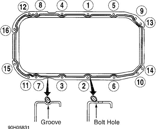
1)To install, reverse removal procedure. Apply sealant to oil pan flange in a continuous .16" (4 mm) diameter bead. See Fig. 12. Install oil pan within 15 minutes of applying sealant.
2)Tighten bolts to specification in proper sequence. See TORQUE SPECIFICATIONS TABLE at the end of this article. Wait at least 30 minutes before adding oil and starting engine. On AWD models, refill transfer assembly with GL-4 hypoid gear oil. On all models, complete installation by reversing removal procedure.
Fig. 12: Applying Sealant & Tightening Oil Pan Bolts Courtesy of Mitsubishi Motor Sales of America, Inc.
OVERHAUL
CYLINDER HEAD
Cylinder Head
Measure cylinder head height. Measure warpage at gasket and manifold surfaces. Resurface head if warpage exceeds specification. See appropriate CYLINDER HEAD table under ENGINE SPECIFICATIONS. Replace cylinder head if it is not within specification after resurfacing.
NOTE: Install valve springs with enamel-coated side toward valve spring retainer.
Valve Springs
Measure free length of valve springs. Measure spring pressure at specified height. Replace springs if not within specification. See appropriate VALVES & VALVE SPRINGS table under ENGINE SPECIFICATIONS. Inspect valve spring for squareness. Replace spring if out-of-square exceeds 4 degrees.
Valve Stem Oil Seals
With valves removed, remove oil seals from cylinder head. Lubricate new seals with engine oil. Using Valve Stem Oil Seal Installer (MD998377 for Montero, MD998729 for Pickup, Ram-50), install valve stem oil seal.
Valve Guides
1)Measure valve stem oil clearance. Replace valve guide if not within specification. See appropriate VALVES & VALVE SPRINGS table under ENGINE SPECIFICATIONS.
2)Using rod of Valve Guide Remover/Installer (MD998115), drive out valve guide toward combustion chamber side of cylinder head. Note length of valve guides.
3)On all models, cylinder head must be bored to install oversized valve guide once guide is removed. DO NOT install valve guide of same O.D. as old guide. Bore cylinder head to specification for oversize valve guide. See appropriate OVERSIZE VALVE GUIDE SPECIFICATIONS table.
4)Install proper length valve guide. Intake guide is 1.73" (43.9 mm) long; exhaust guide is 1.89" (48.0 mm) long. On all models, position cylinder head with combustion chamber downward.
5)Using valve guide remover/installer, install valve guide. Remover/installer sets valve guide height. On all models, ensure valve slides smoothly in valve guide. Recondition valve seat.
OVERSIZE VALVE GUIDE SPECIFICATIONS TABLE
Oversize: In. (mm) |
Size Mark |
Bore Size: In. (mm) |
||
.002 |
(.05) ........... |
5 ... |
.5138-.5147 |
(13.050-13.073) |
.010 |
(.25) .......... |
25 ... |
.5217-.5224 |
(13.251-13.269) |
.020 |
(.51) .......... |
50 ... |
.5315-.5323 |
(13.500-13.520) |
Valve Seat
1)Measure valve spring installed height after valve and valve seat have been reconditioned and lightly lapped. With valve assembly installed, measure installed height of valve spring between spring seat and retainer. Valve seat must be replaced if measurement exceeds 1.63" (41.4 mm).
2)To replace seat, grind wall until seat can be removed. Machine cylinder head to accommodate an oversize valve seat. See OVERSIZE VALVE SEAT SPECIFICATIONS table. Heat cylinder head to
approximately 480 F (250 C), and install valve seat. Grind valve seat using 45-degree stone. Use 30-degree and 60-degree stones to set seat height.
OVERSIZE VALVE SEAT SPECIFICATIONS TABLE
Application |
|
|
Specification |
||
In. (mm) |
|
|
|
|
In. (mm) |
Intake |
|
|
|
|
|
Bore Depth |
|
|
|
|
|
.012 |
(.3) |
Oversize ............... |
.311-.319 |
(7.9-8.1) |
|
.024 |
(.6) |
Oversize ............... |
.323-.331 |
(8.2-8.4) |
|
Bore Diameter |
|
|
|
||
.012 |
(.3) |
Oversize ..... |
1.7441-1.7453 |
(44.300-44.330) |
|
.024 |
(.6) |
Oversize ..... |
1.7559-1.7571 |
(44.600-44.630) |
|
Exhaust |
|
|
|
|
|
Bore Depth |
|
|
|
|
|
.012 |
(.3) |
Oversize ............... |
.311-.319 |
(7.9-8.1) |
|
.024 |
(.6) |
Oversize ............... |
.323-.331 |
(8.2-8.4) |
|
Bore Diameter |
|
|
|
||
.012 |
(.3) |
Oversize ..... |
1.5079-1.5091 |
(38.300-38.331) |
|
.024 |
(.6) |
Oversize ..... |
1.5197-1.5209 |
(38.600-38.630) |
|
Valves
Disassemble cylinder head. Measure valve stem diameter, valve margin, and overall length. See appropriate VALVES & VALVE SPRINGS table under ENGINE SPECIFICATIONS. Inspect valve for worn stem tip. Measure valve margin after grinding valves. Replace valves if not within specification.
Lash Adjusters
Before installation, submerge lash adjuster in diesel fuel. Using a small wire, hold down internal check valve. Pump plunger up and down 4 or 5 times to bleed air from lash adjuster.
CYLINDER BLOCK ASSEMBLY
Cylinder Block
1)Inspect cylinder block for cracks, warpage, cylinder bore taper, and out-of-round. Replace or repair cylinder block if it is not within specification. See CYLINDER BLOCK table under ENGINE SPECIFICATIONS.
2)Measure cylinder bore and piston skirt diameter. Piston skirt diameter should be measured at 90-degree angle to piston pin. Clearance between piston and cylinder bore must be within specification. See appropriate PISTONS, PINS & RINGS table under ENGINE SPECIFICATIONS.
Piston & Rod Assembly
1)Remove cylinder heads and oil pan. See CYLINDER HEADS and OIL PAN under REMOVAL & INSTALLATION. Remove cylinder ridge. Mark connecting rod and cap for cylinder identification.
2)Note front mark on piston and connecting rod. See Fig. 13. Mark is positioned toward timing belt side of engine. Remove rod cap and piston assembly.
3)Piston ring end gap and side clearance must be within specification. See appropriate PISTONS, PINS & RINGS table under ENGINE SPECIFICATIONS. Install rings onto piston with ring code identification marks toward top of piston. Top ring is marked T1, and No. 2 ring is marked 2R. Lubricate piston, rings, and cylinder bore with engine oil.
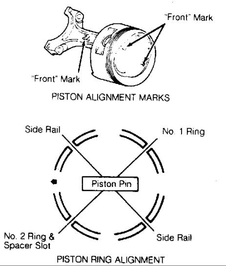
NOTE: Front mark "R" on piston indicates installation in cylinders No. 1, 3, or 5; front mark "L" indicates installation in cylinders No. 2, 4, or 6. Ensure front mark on piston and connecting rod are toward timing belt side of engine. See Fig. 13.
4)Distribute ring end gaps properly around piston. See Fig. 13. Install piston and rod into cylinder bore, with front mark toward timing belt side of engine.
5)Measure bearing clearance using Plastigage. Tighten rod cap nuts to specification. See TORQUE SPECIFICATIONS TABLE at the end of this article. Connecting rod must move freely on crankshaft. Measure connecting rod side play. Repair or replace connecting rod if not within specification. See CONNECTING RODS table under ENGINE SPECIFICATIONS.
Fig. 13: Aligning Piston & Rings
Courtesy of Mitsubishi Motor Sales of America, Inc.
Fitting Pistons
Measure cylinder bore and piston skirt diameter. Piston skirt
diameter should be measured at 90-degree angle to piston pin. Clearance between piston and cylinder bore must be within specification. See appropriate PISTONS, PINS & RINGS table under ENGINE SPECIFICATIONS.
Piston Pin Replacement
1)Note reference mark on top of piston and connecting rod. See Fig. 13. Using press and Piston Pin Remover/Installer (MD998184), remove pin.
2)Inspect piston for cracks and damage. Measure ring side clearance. Replace piston if not within specification. See appropriate PISTONS, PINS & RINGS table under ENGINE SPECIFICATIONS.
3)Measure connecting rod for bend and twist. Replace connecting rod if twist exceeds .004" (.10 mm) or bend exceeds .002" (.05 mm).
NOTE: Install piston with reference mark aligned with connecting rod reference mark. See Fig. 13.
4) Position piston onto connecting rod. Align reference marks on top of piston and connecting rod. See Fig. 13. Lubricate all components with oil. Press piston pin into piston and connecting rod. To install, reverse removal procedure. Ensure piston pin is centered in piston.
Crankshaft & Main Bearings
1)Remove flywheel or drive plate. Remove transaxle/transmission mounting plate and rear seal case. Remove oil pump, oil pan, and oil pick-up tube. Mark connecting rod and main bearing caps for location.
2)Remove connecting rod caps and bearings. Note direction of arrow on main bearing cap. Remove main bearing cap. See Fig. 14. Remove crankshaft. Remove main bearings from cylinder block. Mark bearings for location.
3)Inspect crankshaft for cracks and damaged gear or threads. Measure crankshaft for taper and out-of-round. Replace or repair crankshaft if it is not within specification. See CRANKSHAFT, MAIN & CONNECTING ROD BEARINGS table under ENGINE SPECIFICATIONS.
4)Install upper main bearings into cylinder block. Ensure oil holes are aligned, and bearings are properly seated. Lubricate bearings with engine oil. Install thrust bearing with oil grooves toward crankshaft thrust surface.
5)Install crankshaft into block. Install thrust bearing with oil grooves toward crankshaft thrust surface. Install main bearing caps with arrow toward front of engine.
6)Measure oil clearance using Plastigage. Tighten bolts to specification in proper sequence. See Fig. 14. See TORQUE SPECIFICATIONS TABLE at the end of this article. Clearance must be within specification. See CRANKSHAFT, MAIN & CONNECTING ROD BEARINGS table. If oil clearance is not within specification, replace bearings or crankshaft.
7)Ensure crankshaft rotates freely with main bearing cap installed. Measure crankshaft end play. See CRANKSHAFT, MAIN & CONNECTING ROD BEARINGS table.
8)Install connecting rod caps and bearings. Install components in original locations. Tighten rod nuts to specification. See TORQUE SPECIFICATIONS TABLE at the end of this article. To complete installation, reverse removal procedure. Tighten bolts to specification.
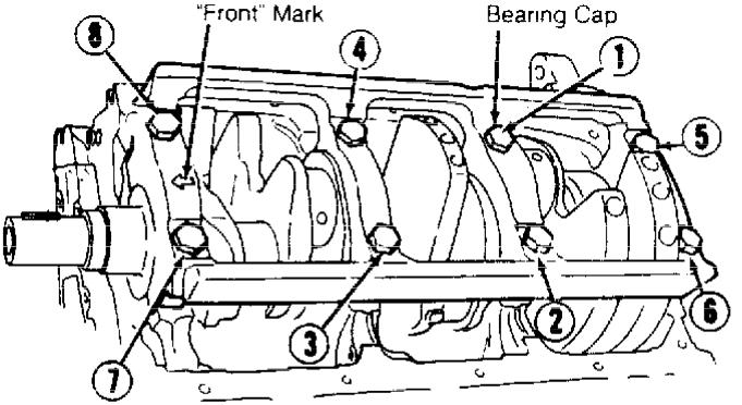
Fig. 14: Tightening Sequence For Main Bearing Cap Bolts Courtesy of Mitsubishi Motor Sales of America, Inc.
Connecting Rod Bearings
1)Mark bearing cap and connecting rod for location. Remove connecting rod cap and bearing. Install replacement bearing.
2)Align reference marks on rod cap and connecting rod. Measure bearing clearance with Plastigage. Connecting rods must move freely on crankshaft. Measure connecting rod side play. See CONNECTING RODS table under ENGINE SPECIFICATIONS.
Crankshaft End Play
If end play is not within specification, inspect thrust bearings and crankshaft. Replace thrust bearing or crankshaft to obtain correct end play. See CRANKSHAFT, MAIN & CONNECTING ROD BEARINGS table under ENGINE SPECIFICATIONS.
ENGINE OILING
ENGINE LUBRICATION SYSTEM
Oil pressure is provided by a rotor-type pump driven by crankshaft. Pressure relief valve is located in oil pump body.
Crankcase Capacity
Montero, Pickup, and Ram-50 oil capacity is 5.0 qts. (4.7L). Add .5 qt. (.4L) when filter is replaced. Add .5 qt. (.4L) with oil cooler.
Oil Pressure
Oil pressure should be at least 11 psi (.8 kg/cm ) at idle and engine oil temperature of 167-194 F (75-90 C).
OIL PUMP
Removal
Remove timing belt and crankshaft sprocket. See TIMING BELT under REMOVAL & INSTALLATION. Remove oil pan. See OIL PAN under REMOVAL & INSTALLATION. Remove oil filter and mounting bracket. Remove oil pump and gasket from cylinder block. Note bolt length and location for installation reference.
Disassembly & Inspection
1)Disassemble pump. Inspect for scoring and cracks. Install rotors into pump body. Measure clearance between driven rotor and pump body. See OIL PUMP SPECIFICATIONS table.
2)Measure rotor side clearance. Replace rotor set or pump assembly if not within specification. Ensure relief valve slides freely in pump body bore. Inspect relief valve spring for damage.
OIL PUMP SPECIFICATIONS TABLE
Application |
|
In. (mm) |
Driven Rotor-To-Pump Body ........ |
.0039-.0071 |
(.099-.180) |
Rotor Side Clearance ............. |
.0016-.0037 |
(.041-.094) |
Reassembly & Installation
1)Reassemble pump. Tighten pump rear cover bolts to specification. See TORQUE SPECIFICATIONS TABLE at the end of this article. Install oil pump and gasket. Align splined teeth of oil pump with crankshaft. Install bolts, and tighten to specification.
2)If oil seal was removed, coat new seal with grease. Using Seal Driver (MD998717), install seal in oil pump until flush with case. Install remaining components.
TORQUE SPECIFICATIONS
TORQUE SPECIFICATIONS TABLE
Application |
Ft. Lbs. (N.m) |
Air Intake Plenum Stay Bolts ............... |
11-14 (15-19) |
Camshaft Bearing Cap Bolt .................. |
14-15 (19-20) |
Camshaft Sprocket Bolt ..................... |
58-72 (79-98) |
Connecting Rod Nut ......................... |
37-38 (50-52) |
Crankshaft Pulley Bolt |
|
Montero .............................. |
108-116 (146-157) |
Pickup & Ram-50 ...................... |
130-137 (176-186) |
Cylinder Head Bolt (1) (Cold Engine) ....... |
65-72 (88-98) |
Drive Plate Bolt ........................... |
53-55 (72-75) |
Exhaust Manifold Nut ....................... |
11-16 (15-22) |
Flywheel Bolt .............................. |
53-55 (72-75) |
Intake Manifold Bolts ...................... |
11-15 (15-20) |
Left Engine Support Bracket Bolt ........... |
15-21 (20-30) |
Main Bearing Cap Bolt ...................... |
55-61 (75-83) |
Oil Pick-Up Tube Bolt ...................... |
11-15 (15-20) |
Rear Engine Support Bracket-To-Engine |
|
Bolt ...................................... |
13-18 (18-25) |
Relief Valve Plug .......................... |
29-36 (39-49) |
Right Engine Support Bracket Bolt |
|
10 x 22-mm ............................... |
25-36 (34-49) |
12 x 22-mm & 12 x 32 mm .................. |
47-61 (64-83) |
Rocker Shaft ............................... |
14-15 (19-20) |
Timing Belt Tensioner Bolt ................. |
16-21 (22-29) |
Water Pump Bolt ............................ |
14-20 |
(19-27) |
|
|
INCH Lbs. (N.m) |
||
Delivery Pipe Bolt ......................... |
84-108 (9-12) |
||
Distributor Adapter Bolt ................. |
108-132 |
(12-15) |
|
Oil Filter Bracket Bolt .................. |
108-120 |
(12-14) |
|
Oil Pan Bolt ................................. |
48-60 (5-7) |
||
Oil Pump Cover Bolt ........................ |
72-108 (8-12) |
||
Oil Pump Mounting Bolt ................... |
108-120 |
(12-14) |
|
Rear Seal Case Bolt ........................ |
84-108 |
(9-12) |
|
Rocker Cover Bolt ............................ |
72-84 (8-9) |
||
Throttle Body Bolt ......................... |
84-108 |
(9-12) |
|
Timing Belt Cover Bolt ..................... |
84-108 |
(9-12) |
|
Transmission Mounting Plate Bolt ........... |
84-108 |
(9-12) |
|
(1) - Tighten in 2 stages in proper sequence. See Fig. 3.
ENGINE SPECIFICATIONS
GENERAL ENGINE SPECIFICATIONS
GENERAL ENGINE SPECIFICATIONS TABLE
Application |
Specification |
||
Displacement ........................ |
181.4 Cu. In. |
(3.0L) |
|
Bore .................................... |
3.587" (91.1 |
mm) |
|
Stroke .................................. |
2.992" (76.0 |
mm) |
|
Compression Ratio .................................. |
|
8.9:1 |
|
Fuel System .......................................... |
|
|
PFI |
Horsepower @ RPM .............................. |
143 |
@ 5000 |
|
Torque Ft. Lbs. @ RPM ......................... |
168 |
@ 2500 |
|
CRANKSHAFT, MAIN & CONNECTING ROD BEARINGS SPECS
CRANKSHAFT, MAIN & CONNECTING ROD BEARINGS SPECS TABLE
Application |
In. (mm) |
|
Crankshaft |
|
|
End Play |
|
|
Standard ..................... |
.0020-.0098 (.050-.250) |
|
Limit |
..................................... |
.012 (.30) |
Main Bearings |
|
|
Journal |
Diameter ........................... |
2.36 (59.9) |
Journal |
Out-Of-Round ...................... |
.0002 (.005) |
Journal |
Taper ............................. |
.0002 (.005) |
Oil Clearance |
|
|
Standard ..................... |
.0008-.0020 (.020-.051) |
|
Limit |
..................................... |
.004 (.10) |
Connecting Rod Bearings |
|
|
Journal |
Diameter ......................... |
1.965 (49.91) |
Journal |
Out-Of-Round ...................... |
.0002 (.005) |
Journal |
Taper ............................. |
.0002 (.005) |
Oil Clearance |
|
|
Standard ..................... |
.0008-.0020 (.020-.051) |
|
Limit |
..................................... |
.004 (.10) |
CONNECTING RODS SPECIFICATIONS
CONNECTING RODS SPECIFICATIONS TABLE
Application |
In. (mm) |
|
Maximum Bend .................................. |
.002 |
(.05) |
Maximum Twist (Total Rod Length) .............. |
.004 |
(.10) |
Side Play |
|
|
Standard ....................... |
.0039-.0099 (.099-.251) |
|
Limit ....................................... |
.016 |
(.41) |
PISTONS, PINS & RINGS SPECIFICATIONS
PISTONS, PINS & RINGS SPECIFICATIONS TABLE
Application |
In. (mm) |
|
Pistons |
|
|
Clearance ...................... |
.0008-.0016 (.020-.040) |
|
Diameter ................................. |
3.587 (91.11) |
|
Pins |
|
|
Piston Fit ........................................ |
(1) |
|
Rod Fit ........................................... |
(2) |
|
Rings |
|
|
No. |
1 |
|
End Gap |
|
|
|
Standard ................... |
.0118-.0177 (.300-.450) |
|
Limit ................................... |
.031 (.79) |
Side Clearance |
|
|
|
Standard ................... |
.0020-.0035 (.051-.089) |
|
Limit ................................... |
.004 (.10) |
No. |
2 |
|
End Gap |
|
|
|
Standard ................... |
.0098-.0157 (.249-.399) |
|
Limit ................................... |
.031 (.79) |
Side Clearance |
|
|
|
Standard ................... |
.0008-.0024 (.020-.060) |
|
Limit ................................... |
.004 (.10) |
No. |
3 (Oil) |
|
End Gap |
|
|
|
Standard ....................... |
.008-.024 (.20-.60) |
|
Limit ................................... |
.039 (.99) |
(1)- Slip.
(2)- At press load of 1653-3858 lbs. (750-1750 kg).
CYLINDER BLOCK SPECIFICATIONS
CYLINDER BLOCK SPECIFICATIONS TABLE
Application |
In. (mm) |
Cylinder Bore |
|
Standard Diameter ........................ |
3.590 (91.19) |
Maximum Taper & Out-Of-Round .............. |
.0008 (.020) |
Maximum Deck Warpage |
|
Standard .................................... |
.002 (.05) |
Limit ..................................... |
.0040 (.102) |
VALVES & VALVE SPRINGS SPECIFICATIONS
VALVES & VALVE SPRINGS SPECIFICATIONS TABLE
Application |
Specification |
Intake Valves |
|
Face Angle .................................... |
45-45.5 |
Minimum Margin .......................... |
.028" (.71 mm) |
Standard Length ..................... |
4.055" (103.00 mm) |
Stem Diameter ............ |
.3134-.3140" (7.960-7.976 mm) |
Exhaust Valves |
|
Face Angle .................................... |
45-45.5 |
Minimum Margin ......................... |
.059" (1.50 mm) |
Standard Length ..................... |
4.043" (102.70 mm) |
Stem Diameter ............ |
.3122-.3130" (7.930-7.950 mm) |
Valve Springs |
|
Free Length |
|
Standard ........................... |
1.960" (49.78 mm) |
Limit .............................. |
1.920" (48.77 mm) |
Installed Height ..................... |
1.591" (40.41 mm) |
Out-Of-Square |
|
Standard .......................................... |
2 |
Limit ............................................. |
4 |
Pressure (Valve Closed) .. |
(1) 74 @ 1.591 (33.6 @ 40.41) |
(1) - Lbs. @ In. (kg @ mm).
CYLINDER HEAD SPECIFICATIONS
CYLINDER HEAD SPECIFICATIONS TABLE
Application |
Specification |
Cylinder Head Height ................... |
3.310" (84.07 mm) |
Maximum Warpage ........................... |
.008" (.20 mm) |
Valve Seats (Intake & Exhaust) |
45 -45.5 |
Seat Angle .................................... |
|
Seat Width .................... |
.035-.051" (.90-1.30 mm) |
Seat Bore Diameter ....... |
1.732-1.742" (44.00-44.25 mm) |
Valve Guides |
|
Intake Valve |
|
Valve Guide Cylinder |
|
Head Bore I.D. ........ |
.5118-.5189" (13.00-13.18 mm) |
Valve Guide Length .................... |
1.732" (44 mm) |
Stem-To-Guide Clearance |
|
Standard ............... |
.0012-.0024" (.030-.060 mm) |
Limit ............................... |
.004" (.10 mm) |
Exhaust Valve |
|
Valve Guide Cylinder |
|
Head Bore I.D. ........ |
.5118-.5189" (13.00-13.18 mm) |
Valve Guide Length .................... |
1.890" (48 mm) |
Stem-To-Guide Clearance |
|
Standard ............... |
.0020-.0035" (.050-.090 mm) |
Limit ............................... |
.006" (.15 mm) |
CAMSHAFT SPECIFICATIONS
CAMSHAFT SPECIFICATIONS TABLE
Application |
In. (mm) |
End Play |
|
|
Standard ........................... |
.004-.008 (0.1-0.2) |
|
Limit ....................................... |
.015 (0.4) |
|
Journal Diameter ............................. |
1.34 (34.0) |
|
Lobe Height |
|
|
Standard ................................. |
1.620 |
(41.15) |
Limit .................................... |
1.600 |
(40.64) |
Oil Clearance .................... |
.0020-.0035 (.050-.090) |
|
ABBREVIATIONS
1993 Mitsubishi Montero
GENERAL INFORMATION
COMMONLY USED ABBREVIATION
"A" ABBREVIATION TABLE
"A" ABBREVIATION TABLE
ABBREVIATION DEFINITION
A Amperes
A/C |
Air Conditioning |
|
A/T |
Automatic Transmission/Transaxle |
|
AAP |
Auxiliary Accelerator Pump |
|
AB |
Air Bleed |
|
ABCV |
Air Bleed Control Valve |
|
ABDC |
After Bottom Dead Center |
|
ABRS |
Air Bag Restraint System |
|
ABS |
Anti-Lock Brake System |
|
AC |
Alternating Current |
|
ACC |
A/C Clutch Compressor |
|
ACCS |
A/C Cycling Switch |
|
ACCUM |
Accumulator |
|
ACCY |
Accessory |
|
ACT |
Air Charge Temperature Sensor |
|
ACV |
Thermactor Air Control Valve |
|
ADJ |
Adjust or Adjustable |
|
ADV |
Advance |
|
AFS |
Airflow Sensor |
|
AI |
Air Injection |
|
AIR or A.I.R. |
Air Injection Reactor |
|
AIS |
Air Injection System |
|
ALCL |
Assembly Line Communications Link |
|
ALDL |
Assembly Line Diagnostic Link |
|
ARC |
Automatic Ride Control |
|
ASCD |
Automatic Speed Control Device |
|
ASCS |
Air Suction Control Solenoid |
|
ASD |
Auto Shutdown |
|
ASDM |
Air Bag System Diagnostic Module |
|
ASV |
Air Suction Valve |
|
ATC |
Automatic Temperature Control |
|
ATDC |
After Top Dead Center |
|
ATF |
Automatic Transmission Fluid |
|
ATS |
Air Temperature Sensor |
|
AXOD |
Automatic Transaxle Overdrive |
|
Abs. |
Absolute |
|
Accy. |
Accessory |
|
Alt. |
Alternator or Altitude |
|
Amp. |
Ampere |
|
Assy. |
Assembly |
|
Auto. |
Automatic |
|
Aux. |
Auxiliary |
|
Avg. |
Average |
|
"B" ABBREVIATION TABLE
"B" ABBREVIATION TABLE
ABBREVIATION DEFINITION
B/P Backpressure
BAC |
By-Pass Air Control |
|
BAP |
Barometric Absolute Pressure Sensor |
|
BARO |
Barometric |
|
BBDC |
Before Bottom Dead Center |
|
BCM |
Body Control Module |
|
BDC |
Bottom Dead Center |
|
BHP |
Brake Horsepower |
|
BLK |
Black |
|
BLU |
Blue |
|
BMAP |
Barometric & Manifold Absolute Pressure Sensor |
|
BOO |
Brake On-Off Switch |
|
BP |
Barometric Pressure sensor |
|
BPS |
Barometric Pressure Sensor |
|
BPT |
Backpressure Transducer |
|
BRN |
Brown |
|
BTDC |
Before Top Dead Center |
|
BTU |
British Thermal Unit |
|
BVSV |
Bimetallic Vacuum Switching Valve |
|
Baro. |
Barometric |
|
Batt. |
Battery |
|
Bbl. |
Barrel (Example: 4-Bbl.) |
|
Blst. |
Ballast |
|
Blwr. |
Blower |
|
Brkr. |
Breaker |
|
"C" ABBREVIATION TABLE
"C" ABBREVIATION TABLE
ABBREVIATION DEFINITION
C Celsius (Degrees)
C(3) I |
Computer Controlled Coil Ignition |
|
C(4) |
Computer Controlled Catalytic Converter |
|
CANP |
Canister Purge solenoid |
|
CARB |
California Air Resources Board |
|
CAT |
Catalytic Converter |
|
CB |
Circuit Breaker |
|
CBD |
Closed Bowl Distributor |
|
CBVV |
Carburetor Bowl Vent Valve |
|
cc |
Cubic Centimeter |
|
CCC |
Computer Command Control |
|
CCD |
Computer Controlled Dwell |
|
CCM |
Central Control Module |
|
CCO |
Converter Clutch Override |
|
CCOT |
Cycling Clutch Orifice Tube |
|
CCW |
Counterclockwise |
|
CDI |
Capacitor Discharge Ignition |
|
CEC |
Computerized Engine Control |
|
CFI |
Central Fuel Injection |
|
CID |
Cubic Inch Displacement |
|
CID |
Cylinder Identification sensor |
|
CIS |
Continuous Injection System |
|
CIS-E |
Continuous Injection System-Electronic |
|
CKT |
Circuit |
|
CLR |
Clear |
|
CNG |
Compressed Natural Gas |
|
CO |
Carbon Monoxide |
|
CO2 |
Carbon Dioxide |
|
CONV |
Convertible |
|
CP |
Canister Purge |
|
CPA |
Connector Position Assurance |
|
CPS |
Crank Position Sensor |
|
CTS |
Coolant Temperature Sensor |
|
CV |
Check Valve or Constant Velocity |
|
CVC |
Constant Vacuum Control |
|
CW |
Clockwise |
|
CYL or Cyl. |
Cylinder |
|
Calif. |
California |
|
Carb. |
Carburetor |
|
Chrg. |
Charging |
|
Circ. |
Circuit |
|
Cntrl. |
Control |
|
Comp. |
Compressor or Compartment |
|
Conn. |
Connector |
|
Cont. |
Continued |
|
Conv. |
Convertible or Converter |
|
Cu. In. |
Cubic Inch |
|
Cyl. |
Cylinder |
|
"D" ABBREVIATION TABLE
"D" ABBREVIATION TABLE
ABBREVIATION DEFINITION
"D" Drive
DBC |
Dual Bed Catalyst |
|
DC |
Direct Current or Discharge |
|
DDD |
Dual Diaphragm Distributor |
|
DERM |
Diagnostic Energy Reserve Module |
|
DFI |
Digital Fuel Injection |
|
DIC |
Driver Information Center |
|
DIS |
Direct Ignition System |
|
DIS |
Distributorless Ignition System |
|
DIST |
Distribution |
|
DISTR |
Distributor |
|
DK BLU |
Dark Blue |
|
DK GRN |
Dark Green |
|
DME |
Digital Motor Electronics (Motronic System) |
|
DOHC |
Double Overhead Cam |
|
DOT |
Department of Transportation |
|
DP |
Dashpot |
|
DRB-II |
Diagnostic Readout Box |
|
DVOM |
Digital Volt/Ohm Meter (see VOM) |
|
Def. |
Defogger or Defroster |
|
Def. |
Defrost |
|
Defog. |
Defogger |
|
Diag. |
Diagnostic |
|
Dist. |
Distributor or Distribution |
|
Dr. |
Door |
|
"E" ABBREVIATION TABLE
"E" ABBREVIATION TABLE
ABBREVIATION DEFINITION
EAC Electric Assist Choke
EACV |
Electric Air Control Valve |
|
|
EBCM |
Electronic |
Brake Control Module |
|
ECA |
Electronic |
Control Assembly |
|
ECAT |
Electronically Controlled Automatic Transaxle |
|
|
ECM |
Electronic |
Control Module |
|
ECT |
Engine Coolant Temperature Sensor |
|
|
ECU |
Electronic |
Control Unit or Engine Control Unit |
|
EDF |
Electric Drive Fan relay assembly |
|
|
EDIS |
Electronic |
Distributorless Ignition System |
|
EEC |
Electronic |
Engine Control |
|
EECS |
Evaporative Emission Control System |
|
|
EEPROM |
Electronically Erasable PROM |
|
|
EFE |
Early Fuel |
Evaporation |
|
EFI |
Electronic |
Fuel Injection |
|
EGO |
Exhaust Gas Oxygen sensor (see HEGO) |
|
|
EGR |
Exhaust Gas Recirculation system |
|
|
EGRC |
EGR Control solenoid or system |
|
|
EGRV |
EGR Vent solenoid or system |
|
|
EMR |
Emission Maintenance Reminder Module |
|
|
ESA |
Electronic |
Spark Advance |
|
ESC |
Electronic |
Spark Control |
|
EST |
Electronic |
Spark Timing |
|
ETR |
Emergency Tensioning Retractor |
|
|
EVAP |
Fuel Evaporative System |
|
|
EVIC |
Electronic |
Vehicle Information Center |
|
EVO |
Electronic |
Variable Orifice |
|
EVP |
EGR Valve Position Sensor |
|
|
EVR |
EGR Valve Regulator |
|
|
EVRV |
Electronic |
Vacuum Regulator Valve |
|
Elect. |
Electronic |
|
|
Eng. |
Engine |
|
|
Evap. |
Evaporative |
|
|
Exc. |
Except |
|
|
"F" ABBREVIATION TABLE
"F" ABBREVIATION TABLE
ABBREVIATION DEFINITION
F Fahrenheit (Degrees)
F/B |
Fuse Block |
|
FBC |
Feedback Carburetor |
|
FI |
Fuel Injector or Fuel Injection |
|
FICD |
Fast Idle Control Device |
|
FIPL |
Fuel Injector Pump Lever |
|
FP |
Fuel Pump |
|
FPM |
Fuel Pump Monitor |
|
FPR-VSV |
Fuel Pressure Regulator Vacuum Switching Valve |
|
FWD |
Front Wheel Drive |
|
Fed. |
Federal |
|
Ft. Lbs. |
Foot Pounds |
|
"G" ABBREVIATION TABLE
"G" ABBREVIATION TABLE
ABBREVIATION DEFINITION
g grams
GND or GRND |
Ground |
|
GRN |
Green |
|
GRY |
Gray |
|
Ga. |
Gauge |
|
Gals. |
gallons |
|
Gov. |
Governor |
|
"H" ABBREVIATION TABLE
"H" ABBREVIATION TABLE
ABBREVIATION DEFINITION
H/D Heavy Duty
HAC |
High Altitude Compensation |
|
HC |
Hydrocarbons |
|
HEDF |
High Speed Electro Drive Fan relay or circuit |
|
HEGO |
Heated Exhaust Gas Oxygen Sensor |
|
HEGOG |
HEGO Ground circuit |
|
HEI |
High Energy Ignition |
|
HLDT |
Headlight |
|
HO |
High Output |
|
HP |
High Performance |
|
HSC |
High Swirl Combustion |
|
HSO |
High Specific Output |
|
HTR |
Heater |
|
HVAC |
Heating |
|
Headlt. |
Headlight |
|
Hg |
Mercury |
|
Hgt. |
Height |
|
Htr. |
Heater |
|
Hz |
Hertz (Cycles Per Second) |
|
"I" ABBREVIATION TABLE
"I" ABBREVIATION TABLE
ABBREVIATION DEFINITION
I.D. Inside Diameter
IAC |
Idle Air Control |
|
IACV |
Idle Air Control Valve |
|
IC |
Integrated Circuit |
|
ID |
Identification |
|
IDM |
Ignition Diagnostic Monitor |
|
IGN |
Ignition system or circuit |
|
ILC |
Idle Load Compensator |
|
In. Hg |
Inches of Mercury |
|
INCH Lbs. |
Inch Pounds |
|
INFL REST |
Inflatable Restraint |
|
INJ |
Injector or Injection |
|
IP |
Instrument Panel |
|
IPC |
Instrument Panel Cluster |
|
ISA |
Idle Speed Actuator |
|
ISC |
Idle Speed Control |
|
ISS |
Idle Stop Solenoid |
|
ITS |
Idle Tracking Switch |
|
IVSV |
Idle Vacuum Switching Valve |
|
Ign. |
Ignition |
|
In. |
Inches |
|
Inj. |
Injector |
|
"J" ABBREVIATION TABLE
"J" ABBREVIATION TABLE
ABBREVIATION DEFINITION
J/B Junction Block
"K" ABBREVIATION TABLE
"K" ABBREVIATION TABLE
ABBREVIATION DEFINITION
k/ohms 1000 ohms (kilo as in k/ohms)
kg |
|
Kilograms (weight) |
|
kg/cm |
|
Kilograms Per Square Centimeter |
|
KAM |
Keep Alive Memory |
|
|
KAPWR |
Keep Alive Power |
|
|
KM/H |
|
Kilometers Per Hour |
|
KOEO |
|
Key On Engine Off |
|
KOER |
|
Key On Engine Running |
|
KS |
|
Knock Sensor |
|
"L" ABBREVIATION TABLE
"L" ABBREVIATION TABLE
ABBREVIATION DEFINITION
L Liter(s)
L/D |
Light Duty |
|
LCD |
Liquid Crystal Display |
|
LED |
Light Emitting Diode |
|
LH |
Left Hand |
|
LOS |
Limited Operation Strategy |
|
LT BLU |
Light Blue |
|
LT GRN |
Light Green |
|
LUS |
Lock-Up Solenoid |
|
Lbs. |
Pounds |
|
Lt(s). |
Light(s) |
|
Lugg. |
Luggage |
|
"M" ABBREVIATION TABLE
"M" ABBREVIATION TABLE
ABBREVIATION DEFINITION
mA Milliamps
mV |
Millivolts |
|
mfd. |
Microfarads |
|
Loading...